JP2019188558A - Tool selection device and machine learning device - Google Patents
Tool selection device and machine learning device Download PDFInfo
- Publication number
- JP2019188558A JP2019188558A JP2018085768A JP2018085768A JP2019188558A JP 2019188558 A JP2019188558 A JP 2019188558A JP 2018085768 A JP2018085768 A JP 2018085768A JP 2018085768 A JP2018085768 A JP 2018085768A JP 2019188558 A JP2019188558 A JP 2019188558A
- Authority
- JP
- Japan
- Prior art keywords
- tool
- machining
- conditions
- data relating
- data
- Prior art date
- Legal status (The legal status is an assumption and is not a legal conclusion. Google has not performed a legal analysis and makes no representation as to the accuracy of the status listed.)
- Granted
Links
Images


Classifications
-
- G—PHYSICS
- G05—CONTROLLING; REGULATING
- G05B—CONTROL OR REGULATING SYSTEMS IN GENERAL; FUNCTIONAL ELEMENTS OF SUCH SYSTEMS; MONITORING OR TESTING ARRANGEMENTS FOR SUCH SYSTEMS OR ELEMENTS
- G05B13/00—Adaptive control systems, i.e. systems automatically adjusting themselves to have a performance which is optimum according to some preassigned criterion
- G05B13/02—Adaptive control systems, i.e. systems automatically adjusting themselves to have a performance which is optimum according to some preassigned criterion electric
- G05B13/0265—Adaptive control systems, i.e. systems automatically adjusting themselves to have a performance which is optimum according to some preassigned criterion electric the criterion being a learning criterion
-
- G—PHYSICS
- G06—COMPUTING; CALCULATING OR COUNTING
- G06N—COMPUTING ARRANGEMENTS BASED ON SPECIFIC COMPUTATIONAL MODELS
- G06N20/00—Machine learning
-
- B—PERFORMING OPERATIONS; TRANSPORTING
- B23—MACHINE TOOLS; METAL-WORKING NOT OTHERWISE PROVIDED FOR
- B23Q—DETAILS, COMPONENTS, OR ACCESSORIES FOR MACHINE TOOLS, e.g. ARRANGEMENTS FOR COPYING OR CONTROLLING; MACHINE TOOLS IN GENERAL CHARACTERISED BY THE CONSTRUCTION OF PARTICULAR DETAILS OR COMPONENTS; COMBINATIONS OR ASSOCIATIONS OF METAL-WORKING MACHINES, NOT DIRECTED TO A PARTICULAR RESULT
- B23Q15/00—Automatic control or regulation of feed movement, cutting velocity or position of tool or work
- B23Q15/20—Automatic control or regulation of feed movement, cutting velocity or position of tool or work before or after the tool acts upon the workpiece
- B23Q15/22—Control or regulation of position of tool or workpiece
-
- G—PHYSICS
- G05—CONTROLLING; REGULATING
- G05B—CONTROL OR REGULATING SYSTEMS IN GENERAL; FUNCTIONAL ELEMENTS OF SUCH SYSTEMS; MONITORING OR TESTING ARRANGEMENTS FOR SUCH SYSTEMS OR ELEMENTS
- G05B19/00—Programme-control systems
- G05B19/02—Programme-control systems electric
- G05B19/18—Numerical control [NC], i.e. automatically operating machines, in particular machine tools, e.g. in a manufacturing environment, so as to execute positioning, movement or co-ordinated operations by means of programme data in numerical form
- G05B19/4093—Numerical control [NC], i.e. automatically operating machines, in particular machine tools, e.g. in a manufacturing environment, so as to execute positioning, movement or co-ordinated operations by means of programme data in numerical form characterised by part programming, e.g. entry of geometrical information as taken from a technical drawing, combining this with machining and material information to obtain control information, named part programme, for the NC machine
- G05B19/40931—Numerical control [NC], i.e. automatically operating machines, in particular machine tools, e.g. in a manufacturing environment, so as to execute positioning, movement or co-ordinated operations by means of programme data in numerical form characterised by part programming, e.g. entry of geometrical information as taken from a technical drawing, combining this with machining and material information to obtain control information, named part programme, for the NC machine concerning programming of geometry
- G05B19/40935—Selection of predetermined shapes and defining the dimensions with parameter input
-
- G—PHYSICS
- G05—CONTROLLING; REGULATING
- G05B—CONTROL OR REGULATING SYSTEMS IN GENERAL; FUNCTIONAL ELEMENTS OF SUCH SYSTEMS; MONITORING OR TESTING ARRANGEMENTS FOR SUCH SYSTEMS OR ELEMENTS
- G05B19/00—Programme-control systems
- G05B19/02—Programme-control systems electric
- G05B19/18—Numerical control [NC], i.e. automatically operating machines, in particular machine tools, e.g. in a manufacturing environment, so as to execute positioning, movement or co-ordinated operations by means of programme data in numerical form
- G05B19/4093—Numerical control [NC], i.e. automatically operating machines, in particular machine tools, e.g. in a manufacturing environment, so as to execute positioning, movement or co-ordinated operations by means of programme data in numerical form characterised by part programming, e.g. entry of geometrical information as taken from a technical drawing, combining this with machining and material information to obtain control information, named part programme, for the NC machine
- G05B19/40937—Numerical control [NC], i.e. automatically operating machines, in particular machine tools, e.g. in a manufacturing environment, so as to execute positioning, movement or co-ordinated operations by means of programme data in numerical form characterised by part programming, e.g. entry of geometrical information as taken from a technical drawing, combining this with machining and material information to obtain control information, named part programme, for the NC machine concerning programming of machining or material parameters, pocket machining
- G05B19/40938—Tool management
-
- G—PHYSICS
- G05—CONTROLLING; REGULATING
- G05B—CONTROL OR REGULATING SYSTEMS IN GENERAL; FUNCTIONAL ELEMENTS OF SUCH SYSTEMS; MONITORING OR TESTING ARRANGEMENTS FOR SUCH SYSTEMS OR ELEMENTS
- G05B2219/00—Program-control systems
- G05B2219/30—Nc systems
- G05B2219/31—From computer integrated manufacturing till monitoring
- G05B2219/31352—Expert system integrates knowledges to control workshop
-
- G—PHYSICS
- G05—CONTROLLING; REGULATING
- G05B—CONTROL OR REGULATING SYSTEMS IN GENERAL; FUNCTIONAL ELEMENTS OF SUCH SYSTEMS; MONITORING OR TESTING ARRANGEMENTS FOR SUCH SYSTEMS OR ELEMENTS
- G05B2219/00—Program-control systems
- G05B2219/30—Nc systems
- G05B2219/31—From computer integrated manufacturing till monitoring
- G05B2219/31407—Machining, work, process finish time estimation, calculation
-
- G—PHYSICS
- G05—CONTROLLING; REGULATING
- G05B—CONTROL OR REGULATING SYSTEMS IN GENERAL; FUNCTIONAL ELEMENTS OF SUCH SYSTEMS; MONITORING OR TESTING ARRANGEMENTS FOR SUCH SYSTEMS OR ELEMENTS
- G05B2219/00—Program-control systems
- G05B2219/30—Nc systems
- G05B2219/31—From computer integrated manufacturing till monitoring
- G05B2219/31418—NC program management, support, storage, distribution, version, update
-
- G—PHYSICS
- G05—CONTROLLING; REGULATING
- G05B—CONTROL OR REGULATING SYSTEMS IN GENERAL; FUNCTIONAL ELEMENTS OF SUCH SYSTEMS; MONITORING OR TESTING ARRANGEMENTS FOR SUCH SYSTEMS OR ELEMENTS
- G05B2219/00—Program-control systems
- G05B2219/30—Nc systems
- G05B2219/49—Nc machine tool, till multiple
- G05B2219/49065—Execute learning mode first for determining adaptive control parameters
-
- Y—GENERAL TAGGING OF NEW TECHNOLOGICAL DEVELOPMENTS; GENERAL TAGGING OF CROSS-SECTIONAL TECHNOLOGIES SPANNING OVER SEVERAL SECTIONS OF THE IPC; TECHNICAL SUBJECTS COVERED BY FORMER USPC CROSS-REFERENCE ART COLLECTIONS [XRACs] AND DIGESTS
- Y02—TECHNOLOGIES OR APPLICATIONS FOR MITIGATION OR ADAPTATION AGAINST CLIMATE CHANGE
- Y02P—CLIMATE CHANGE MITIGATION TECHNOLOGIES IN THE PRODUCTION OR PROCESSING OF GOODS
- Y02P90/00—Enabling technologies with a potential contribution to greenhouse gas [GHG] emissions mitigation
- Y02P90/02—Total factory control, e.g. smart factories, flexible manufacturing systems [FMS] or integrated manufacturing systems [IMS]
Abstract
Description
本発明は、適切な工具の選定及び切削条件の決定を行う工具選定装置及び機械学習装置に関する。 The present invention relates to a tool selection device and a machine learning device for selecting an appropriate tool and determining cutting conditions.
工作機械でワークの加工を行う場合には、該加工に用いる工具の選定と、選定された工具による加工における切削条件の決定が必要である。工具の選定や切削条件の決定は、加工計画段階で、工具のカタログ本や、工具メーカの準備した工具選定ツールを用いて、使用工具および切削条件(主軸回転数、送り)を仮決定し、仮決定した工具及び切削条件での試し加工を繰り返しながら切削条件の調整を行い、問題ないことを確認した上で、工具及び切削条件を決定する。 When machining a workpiece with a machine tool, it is necessary to select a tool to be used for the machining and to determine a cutting condition in machining with the selected tool. Tool selection and cutting conditions are determined at the machining planning stage by temporarily determining the tools to be used and the cutting conditions (spindle speed, feed) using the tool catalog and tool selection tool prepared by the tool manufacturer. The cutting conditions are adjusted while repeating the trial machining with the determined tools and cutting conditions, and after confirming that there is no problem, the tools and cutting conditions are determined.
工作機械の加工に用いる切削条件を決定する従来技術として、特許文献1には、加工において許容できる工具負荷の条件に基づいて切削条件を決定する技術が開示されている。
As a conventional technique for determining a cutting condition used for machining a machine tool,
切削条件は、主軸出力や剛性等の機械特性や、ワークの材質や加工種類等の加工条件による部分が大きいが、カタログ本や工具選定ツールにより提供される情報は汎用的なものであるため、加工に使用する機械や加工条件に合致した条件を導出するには何度も試し加工を行い、その加工結果を検証する必要があり、これには時間と手間がかかる。また、切削条件を調整すると、これに伴い加工プログラムあるいは工具データの修正もする必要があり、この操作にも時間を要する。更に、サイクルタイムを重視した運転か、加工精度や工具寿命を重視した運転かによって、切削条件の調整が更に必要となる。 Cutting conditions are largely dependent on machine characteristics such as spindle output and rigidity, and machining conditions such as workpiece materials and machining types, but the information provided by catalog books and tool selection tools is general-purpose. In order to derive conditions that match the machine and processing conditions used for the test, it is necessary to perform trial processing many times and verify the processing results, which takes time and effort. Further, when the cutting conditions are adjusted, it is necessary to correct the machining program or the tool data accordingly, and this operation also takes time. Furthermore, it is necessary to further adjust the cutting conditions depending on whether the operation emphasizes cycle time or the operation emphasizes machining accuracy and tool life.
一方、特許文献1に開示される技術では、切削条件を決定することは可能であっても、その切削条件はある工具を用いた加工において利用可能なものであり、加工の目的に合わせて更に適切な工具を選定してくれるものではない。
On the other hand, in the technique disclosed in
そこで本発明の目的は、適切な工具の選定及び切削条件の決定を行うことが可能な工具選定装置及び機械学習装置を提供することである。 Therefore, an object of the present invention is to provide a tool selection device and a machine learning device capable of selecting an appropriate tool and determining cutting conditions.
本発明の工具選定装置は、加工条件(ワーク材質、加工種類、切込量、切削幅)と運転の要求仕様(速度、精度、工具寿命)を満たす主軸負荷のピーク値に対し、最適な工具および切削条件(回転数、送り速度)を導出する仕組みを機械学習を用いて実現する。加工プログラムや工具データは、上記の仕組みで導出された工具、切削条件に応じた内容に自動で書換えられる。 The tool selection device of the present invention is suitable for the peak value of the spindle load that satisfies the machining conditions (work material, machining type, depth of cut, cutting width) and the required specifications for operation (speed, accuracy, tool life). And a mechanism for deriving cutting conditions (rotation speed, feed rate) is realized using machine learning. The machining program and the tool data are automatically rewritten to the contents according to the tool and cutting conditions derived by the above mechanism.
作業者は、段取工程で加工プログラムやワーク情報を入力した時点で、上記仕組みを用いることで、試運転および加工プログラムと工具データの変更操作を行うことなく、加工に即した工具選定および切削条件の設定を行うことができる。 When the operator inputs the machining program and workpiece information in the setup process, the tool selection and cutting conditions in accordance with the machining can be performed without using trial operation and changing the machining program and tool data. Can be set.
そして、本発明の一態様は、指定された条件の下でワークの加工に使用可能な工具種別を選定する工具選定装置であって、指定された条件に対してワークの加工に使用可能な工具種別を学習する機械学習装置を備え、前記機械学習装置は、加工条件に係るデータ、切削条件に係るデータ、加工結果に係るデータ、及び工具に係るデータを、環境の現在状態を表す状態変数として観測する状態観測部と、前記状態変数を用いて、前記工具に係るデータに対する、前記加工条件に係るデータ、前記切削条件に係るデータ、及び加工結果に係るデータの分布を学習する学習部と、を備える工具選定装置である。 One aspect of the present invention is a tool selection device that selects a tool type that can be used for machining a workpiece under a designated condition, and is a tool that can be used for machining a workpiece under a designated condition. A machine learning device that learns a type, the machine learning device includes data relating to a machining condition, data relating to a cutting condition, data relating to a machining result, and data relating to a tool as state variables representing a current state of an environment. A state observing unit to observe, and a learning unit that learns the distribution of data related to the machining condition, data related to the cutting condition, and data related to the machining result with respect to the data related to the tool, using the state variable; It is a tool selection apparatus provided with.
本発明の他の態様は、指定された条件の下でワークの加工に使用可能な工具種別を選定する工具選定装置であって、指定された条件に対してワークの加工に使用可能な工具種別を学習した機械学習装置を備え、前記機械学習装置は、加工条件に係るデータ、切削条件に係るデータ、及び加工結果に係るデータを、環境の現在状態を表す状態変数として観測する状態観測部と、加工に用いられた工具に係るデータに対する、加工条件に係るデータ、切削条件に係るデータ、及び加工結果に係るデータの分布を学習した学習部と、前記状態観測部が観測した状態変数と、前記学習部による学習結果に基づいて、前記状態変数により指定された条件の下で使用可能な工具種別を判定して出力する判定部と、を備える工具選定装置である。 Another aspect of the present invention is a tool selection device for selecting a tool type that can be used for machining a workpiece under a specified condition, and the tool type that can be used for machining a workpiece with respect to a specified condition. A machine learning device that learns the data, and the machine learning device observes data relating to machining conditions, data relating to cutting conditions, and data relating to machining results as state variables representing the current state of the environment, and A learning unit that learns data relating to machining conditions, data relating to cutting conditions, and data relating to machining results with respect to data relating to the tool used for machining, and a state variable observed by the state observation unit, And a determination unit that determines and outputs a usable tool type under the condition specified by the state variable based on a learning result by the learning unit.
本発明の他の態様は、指定された条件に対してワークの加工に使用可能な工具種別を学習する機械学習装置であって、加工条件に係るデータ、切削条件に係るデータ、加工結果に係るデータ、及び工具に係るデータを、環境の現在状態を表す状態変数として観測する状態観測部と、前記状態変数を用いて、前記工具に係るデータに対する、前記加工条件に係るデータ、前記切削条件に係るデータ、及び加工結果に係るデータの分布を学習する学習部と、を備える機械学習装置である。 Another aspect of the present invention is a machine learning device that learns a tool type that can be used for machining a workpiece with respect to a specified condition, and relates to data relating to a machining condition, data relating to a cutting condition, and a machining result. Data and data related to the tool, a state observation unit for observing the current state of the environment as a state variable, and using the state variable, the data relating to the tool and the data relating to the machining condition, the cutting condition And a learning unit that learns data distribution and data distribution related to the processing result.
本発明の他の態様は、指定された条件に対してワークの加工に使用可能な工具種別を学習した機械学習装置であって、加工条件に係るデータ、切削条件に係るデータ、及び加工結果に係るデータを、環境の現在状態を表す状態変数として観測する状態観測部と、加工に用いられた工具に係るデータに対する、加工条件に係るデータ、切削条件に係るデータ、及び加工結果に係るデータの分布を学習した学習部と、前記状態観測部が観測した状態変数と、前記学習部による学習結果に基づいて、前記状態変数により指定された条件の下で使用可能な工具種別を判定して出力する判定部と、を備える機械学習装置である。 Another aspect of the present invention is a machine learning device that learns tool types that can be used for machining a workpiece with respect to a specified condition, and includes data relating to a machining condition, data relating to a cutting condition, and a machining result. A state observation unit for observing such data as a state variable representing the current state of the environment, and data relating to machining conditions, data relating to cutting conditions, and data relating to machining results with respect to data relating to tools used for machining Based on the learning unit learning the distribution, the state variable observed by the state observation unit, and the learning result by the learning unit, the tool type that can be used under the condition specified by the state variable is determined and output. And a determination unit that performs the machine learning.
本発明により、機械特性、加工条件、運転で重視する点(速度、精度、工具寿命)といった現場の用途に合致した工具選定および切削条件の導出と適用が容易に行えるようになり、段取り工程にかかる時間の短縮に繋がる。 With the present invention, it becomes possible to easily select and apply tool selection and cutting conditions that match the field application such as mechanical characteristics, machining conditions, and points to be emphasized in operation (speed, accuracy, tool life). This leads to shortening of the time.
以下、本発明の実施形態を図面と共に説明する。
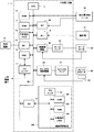
図1は本発明の一実施形態による工具選定装置の要部を示す概略的なハードウェア構成図である。工具選定装置1は、工作機械等の機械を制御する制御装置として実装することができる。また、工具選定装置1は、機械を制御する制御装置と併設されたパソコンや、制御装置とネットワークを介して接続されたセルコンピュータ、ホストコンピュータ、クラウドサーバ等のコンピュータとして実装することが出来る。図1は、工作機械を制御する制御装置として工具選定装置1を実装した場合の例を示している。
Hereinafter, embodiments of the present invention will be described with reference to the drawings.
FIG. 1 is a schematic hardware configuration diagram showing a main part of a tool selection device according to an embodiment of the present invention. The
本実施形態による工具選定装置1が備えるCPU11は、工具選定装置1を全体的に制御するプロセッサである。CPU11は、ROM12に格納されたシステム・プログラムをバス20を介して読み出し、該システム・プログラムに従って工具選定装置1全体を制御する。RAM13には一時的な計算データや表示データ、図示しない入力部を介してオペレータが入力した各種データ等が一時的に格納される。
The
不揮発性メモリ14は、例えば図示しないバッテリでバックアップされるなどして、工具選定装置1の電源がオフされても記憶状態が保持されるメモリとして構成される。不揮発性メモリ14には、インタフェース15を介して外部機器72から読み込まれた加工プログラムや表示器/MDIユニット70を介して入力された加工プログラム、工具選定装置1の各部や工作機械から取得された各種データ(例えば、作業者により入力された加工条件(ワーク材質、加工種類、切込量、切削量)、工具情報、切削条件(主軸回転数、送り速度)、該切削条件による加工時の主軸負荷等)が記憶される。不揮発性メモリ14に記憶された加工プログラムや各種データは、実行時/利用時にはRAM13に展開されても良い。また、ROM12には、公知の解析プログラムなどの各種のシステム・プログラム(後述する機械学習装置100とのやりとりを制御するためのシステム・プログラムを含む)があらかじめ書き込まれている。
The
インタフェース15は、工具選定装置1とアダプタ等の外部機器72と接続するためのインタフェースである。外部機器72側からはプログラムや各種パラメータ等が読み込まれる。また、工具選定装置1内で編集したプログラムや各種パラメータ等は、外部機器72を介して外部記憶手段に記憶させることができる。PMC(プログラマブル・マシン・コントローラ)16は、工具選定装置1に内蔵されたシーケンス・プログラムで工作機械及び該工作機械の周辺装置(例えば、工具交換用のロボットハンドといったアクチュエータ)にI/Oユニット17を介して信号を出力し制御する。また、工作機械の本体に配備された操作盤の各種スイッチ等の信号を受け、必要な信号処理をした後、CPU11に渡す。
The
表示器/MDIユニット70はディスプレイやキーボード等を備えた手動データ入力装置であり、インタフェース18は表示器/MDIユニット70のキーボードからの指令,データを受けてCPU11に渡す。インタフェース19は各軸を手動で駆動させる際に用いる手動パルス発生器等を備えた操作盤71に接続されている。
The display /
工作機械が備える軸を制御するための軸制御回路30はCPU11からの軸の移動指令量を受けて、軸の指令をサーボアンプ40に出力する。サーボアンプ40はこの指令を受けて、工作機械が備える軸を移動させるサーボモータ50を駆動する。軸のサーボモータ50は位置・速度検出器を内蔵し、この位置・速度検出器からの位置・速度フィードバック信号を軸制御回路30にフィードバックし、位置・速度のフィードバック制御を行う。なお、図1のハードウェア構成図では軸制御回路30、サーボアンプ40、サーボモータ50は1つずつしか示されていないが、実際には制御対象となる工作機械に備えられた軸の数だけ用意される。
The
スピンドル制御回路60は、製造機械への主軸回転指令を受け、スピンドルアンプ61にスピンドル速度信号を出力する。スピンドルアンプ61はこのスピンドル速度信号を受けて、製造機械のスピンドルモータ62を指令された回転速度で回転させ、工具を駆動する。スピンドルモータ62にはポジションコーダ63が結合され、ポジションコーダ63が主軸の回転に同期して帰還パルスを出力し、その帰還パルスはCPU11によって読み取られる。
The
インタフェース21は、工具選定装置1と機械学習装置100とを接続するためのインタフェースである。機械学習装置100は、機械学習装置100全体を統御するプロセッサ101と、システム・プログラム等を記憶したROM102、機械学習に係る各処理における一時的な記憶を行うためのRAM103、及び学習モデル等の記憶に用いられる不揮発性メモリ104を備える。機械学習装置100は、インタフェース21を介して工具選定装置1で取得可能な各情報(例えば、作業者により入力された加工条件(ワーク材質、加工種類、切込量、切削量等)、工具情報、切削条件(主軸回転数、送り速度)、動作状態(加工時の主軸負荷等)等)を観測することができる。また、工具選定装置1は、機械学習装置100から出力される工具選定と切削条件の提案を表機器/MDIユニット70に表示し、表示を確認した作業者の選択に基づいて工具選定及び切削条件の設定(加工プログラムの修正、工具データの設定等)を行う。
The
図2は、第1の実施形態による工具選定装置1と機械学習装置100の概略的な機能ブロック図である。図2に示した各機能ブロックは、図1に示した工具選定装置1が備えるCPU11、及び機械学習装置100のプロセッサ101が、それぞれのシステム・プログラムを実行し、工具選定装置1及び機械学習装置100の各部の動作を制御することにより実現される。
FIG. 2 is a schematic functional block diagram of the
本実施形態の工具選定装置1は、不揮発性メモリ14に記憶された加工プログラムや加工条件、切削条件等の設定に基づいて工作機械2が備えるサーボモータ50やスピンドルモータ62等のモータ、及び図示しない工作機械2の周辺機械の制御を行う制御部34と、機械学習装置100が加工に使用可能であると判定した工具種別やその他の条件を表示器/MDIユニットへ表示し、作業者が選定した工具種別やその他の条件を加工に用いる情報として設定する工具選定部36とを備える。
The
一方、工具選定装置1が備える機械学習装置100は、加工条件に係るデータ(ワーク材質、加工種類、切込量、切削量等)、加工結果に係るデータ(加工時の主軸負荷等)、切削条件に係るデータ(主軸回転数、送り速度)に対する工具に係るデータの学習、及び、入力された加工条件に係るデータ(ワーク材質、加工種類、切込量、切削量等)、切削条件に係るデータ(主軸回転数、送り速度)、加工結果に係るデータ(加工時の主軸負荷、加工精度等)に対する工具に係るデータの判定を、いわゆる機械学習により自ら学習するためのソフトウェア(学習アルゴリズム等)及びハードウェア(プロセッサ101等)を含む。工具選定装置1が備える機械学習装置100が学習するものは、加工条件に係るデータ(ワーク材質、加工種類、切込量、切削量等)、切削条件に係るデータ(主軸回転数、送り速度)、加工結果に係るデータ(加工時の主軸負荷、加工精度等)に対する工具に係るデータの相関性を表すモデル構造に相当する。
On the other hand, the
図2に機能ブロックで示すように、工具選定装置1が備える機械学習装置100は、加工条件に係るデータ(ワーク材質、加工種類、切込量、切削量等)を含む加工条件データS1、切削条件に係るデータ(主軸回転数、送り速度)を含む切削条件データS2、加工結果に係るデータ(加工時の主軸負荷、加工精度等)を含む加工結果データS3、工具に係るデータを含む工具データS4を含む状態変数Sを観測する状態観測部106と、状態変数Sを用いて、加工条件に係るデータ(ワーク材質、加工種類、切込量、切削量等)、切削条件に係るデータ(主軸回転数、送り速度)、加工結果に係るデータ(加工時の主軸負荷等)に対して工具に係るデータを関連付けて学習する学習部110と、学習部110が学習した学習済みモデルを用いて加工条件に係るデータ(ワーク材質、加工種類、切込量、切削量等)、切削条件に係るデータ(主軸回転数、送り速度)、加工結果に係るデータ(加工時の主軸負荷、加工精度等)に対する工具に係るデータを判定する判定部122を備える。
As shown in functional blocks in FIG. 2, the
状態観測部106が観測する状態変数Sのうち、加工条件データS1は、工作機械2における加工時に作業者が設定した加工条件として取得することができる。加工条件は、例えば加工対象となるワークの材質、リジットタップ加工やエンドミル加工等といった加工の種類、工具のワークに対する切込量や切削量等を含んでいても良い。状態観測部106は、工作機械2乃至制御装置に入力された加工条件や、加工プログラム内に設定されている加工条件を加工条件データS1として観測する。
Of the state variables S observed by the
状態観測部106が観測する状態変数Sのうち、切削条件データS2は、工作機械2における加工時に作業者が設定した切削条件として取得することができる。切削条件は、例えば主軸回転数、送り速度等を含んでいても良い。状態観測部106は、工作機械2乃至制御装置に入力された切削条件や、加工プログラム内に設定されている切削条件を切削条件データS3として観測する。
Of the state variables S observed by the
状態観測部106が観測する状態変数Sのうち、加工結果データS3は、工作機械2に取付けられた工具(工具データS4として観測される)を用いて、設定された加工条件(加工条件データS1として観測される)、切削条件(切削条件データS2として観測される)の元で行われたワークの加工時に工作機械2(又は工作機械2に取付けられたセンサ等)で検出された送り軸負荷や主軸負荷等の最大値や、加工されたワークの設計との寸法誤差を示す加工誤差等として取得することができる。加工結果データS3は、行われた加工において加工不良や工作機械2の故障、工具の折損等の原因となる物理量を検出した値や、加工の結果を評価するデータや作業者の入力値等を用いることができる。
Of the state variables S observed by the
状態観測部106が観測する状態変数Sのうち、工具データS4は、工作機械2における加工時に用いられる工具に係る情報として取得することができる。工具に係る情報は、例えば工具種別を一意に特定できる情報(例えば、工具の型番)を含んでいても良く、必要に応じて、工具のメーカ、工具の材質(硬度)等を含んでいても良い。工具に係る情報は、主に作業者により入力されたデータや、セルコンピュータ等の上位装置により設定された加工の指示に含まれるデータ等を用いることができる。
Of the state variables S observed by the
学習部110は、機械学習と総称される任意の学習アルゴリズムに従い、状態変数S(加工条件データS1、切削条件データS2、加工結果データS3、工具データS4)に基づくクラスタ分析を行ない、該クラスタ分析により作成されたクラスタを学習済みモデルとして記憶(学習)する。学習部110は、ワークの加工が正常に行われた際に取得された所定数の状態変数S(加工条件データS1、切削条件データS2、加工結果データS3、工具データS4)に基づいてクラスタを作成する。クラスタの作成に使用する状態変数Sは、例えば工場に配置される工作機械2から有線/無線のネットワークを介して取得されて蓄積されたデータ(ビッグデータ)を用いるようにしても良い。このような学習を行うことにより、学習部110は、工具種別(工具データS4)毎の、加工条件(加工条件データS1)、切削条件(切削条件データS2)、及び工作機械2の動作状態(加工結果データS3)の分布をクラスタ集合として解析する。
The
図3は、学習部110が生成するクラスタ集合の例を示す図である。なお、図3では、説明を簡単にするために、データが分布する空間を3次元とし、各軸を切込み量(加工条件データS1)、切削速度(切削条件データS2)、主軸負荷(加工結果データS3)としているが、実際には状態変数Sとして取得した(工具種別(工具データS4)を除く)データ項目を各軸とした多次元空間上にデータが分布することになる。図3に例示するように、学習部110は、少なくとも工具種別毎に異なるクラスタを作成する。図3に示すように、学習部110が作成するクラスタは、工具種別毎に、加工条件、切削条件に対する動作状態の分布の傾向を示す。即ち、それぞれのクラスタは、所定の工具を用いた場合において、設定された加工条件(切込み量)及び切削条件(切削速度)で加工を行った時の動作状態(主軸負荷)の傾向を示すこととなる。このクラスタは、判定部122が、例えば加工条件、切削条件、動作状態の制約が与えられた時の工具の選定の判定をする際に利用される。
FIG. 3 is a diagram illustrating an example of a cluster set generated by the
判定部122は、学習部110がワークの加工が正常に行われた際に取得された状態変数S(加工条件データS1、切削条件データS2、加工結果データS3、工具データS4)に基づいて学習した学習済みモデル(工具種別(工具データS4)毎の、加工条件(加工条件データS1)、切削条件(切削条件データS2)、及び工作機械2の動作状態(加工結果データS3)のクラスタ)と、新たに観測(入力)された加工条件データS1、切削条件データS2、及び加工結果データS3とに基づいて、何れの工具を用いるのが適切であるのかを判定する機能手段である。図3を例として判定部122の動作を説明すると、ワークの加工が正常に行われた場合のクラスタが作成されている状態で、新たに加工条件データS1、切削条件データS2、及び加工結果データS3が観測(入力)されると、判定部122は、当該データと、各工具種別毎のクラスタとの関係を解析し、新たに入力された状態変数Sが属するクラスタに対応する工具種別を、指定された条件で使用可能な工具種別であると判定する。なお、ここで入力される状態変数Sは、所定の範囲を伴っていても良い。例えば、加工結果データS3として、主軸負荷がL1以下であることが主軸負荷の条件として入力された場合には、その範囲に掛かる全てのクラスタに対応する工具種別を、指定された条件で使用可能な工具種別であると判定するようにしても良い。
The
判定部122は、単純に工具種別を判定するだけでなく、新たに観測(入力)された加工条件データS1、切削条件データS2、及び加工結果データS3のクラスタ空間上の位置が、それぞれのクラスタの中心からの距離、又は、新たに観測(入力)された加工条件データS1、切削条件データS2、及び加工結果データS3の位置における、それぞれのクラスタのクラスタ密度に基づいて、指定された条件で使用する工具種別の優先度を判定するようにしても良い。
The
更に、判定部122は、新たに加工条件データS1、切削条件データS2、及び加工結果データS3が観測(入力)に対して使用可能な工具種別を判定した後に、該工具種別の工具を用いて加工する際に設定可能な加工条件乃至切削条件の範囲を判定するようにしても良い。例えば、使用可能な工具種別を判定した後に、該工具種別のクラスタにおける指定されたか好結果(主軸負荷等)を保てる範囲での切削速度の最大値を判定するようにしても良い。
Further, the
上記したように、指定された加工条件、切削条件、及び望まれる加工結果で正常に加工を行うことができる工具種別を演算や目算によらずに自動的に判定することができれば、作業者は必要な加工条件、切削条件、及び望まれる加工結果を入力するだけで(あるいは、CAD/CAM等から読み込ませることで)、適切な工具の選定を迅速に判断することができるようになる。 As described above, if the tool type that can perform normal processing with the specified processing conditions, cutting conditions, and desired processing results can be automatically determined without calculation or calculation, the operator can Only by inputting necessary machining conditions, cutting conditions, and desired machining results (or by reading from CAD / CAM or the like), selection of an appropriate tool can be quickly determined.
そして、判定部122により判定された工具選定部36へと出力される。工具選定部36は、指定された条件の下で使用可能な1乃至複数の工具種別を表示器/MDIユニット70へと表示し、作業者が表示器/MDIユニット70を操作して選定した工具種別を加工に使用する工具として不揮発性メモリ14内に記憶された加工プログラム等に設定する。工具選定部36は、判定部122がそれぞれの工具種別の工具を用いて加工する際に設定可能な加工条件乃至切削条件の範囲を判定している場合には、その加工条件乃至切削条件の範囲も併せて表示し、作業者が指定した加工条件乃至切削条件を変更するか入力を促すようにしても良い。作業者が指定した加工条件乃至切削条件は、工具選定部36により不揮発性メモリ14内に記憶された加工プログラム乃至不揮発性メモリ14上に設けられた設定領域等に設定される。
Then, the data is output to the
図4は、工作機械2を備えた一実施形態によるシステム80を示す。システム80は、同一の機械構成を有する複数の工作機械2と、それら工作機械2を互いに接続するネットワーク82とを備え、複数の工作機械2のうち少なくとも1つが、上記した工具選定装置1を備える工作機械2として構成される。工作機械2は、ワークの加工に必要とされる一般的な工作機械が備える構成を有する。
FIG. 4 shows a
上記構成を有するシステム80は、複数の工作機械2のうちで工具選定装置1を備える工作機械2が、学習部110の学習結果を用いて、工作機械2(工具選定装置1を含まない工作機械2を含む)において指定された加工に係る各条件に対して、該工作機械2において指定された条件の下で使用可能な工具種別を自動的に、しかも正確に求めることができる。また、少なくとも1つの工作機械2の工具選定装置1が、他の複数の工作機械2のそれぞれについて得られた状態変数Sに基づき、全ての工作機械2に共通する学習を行い、その学習結果を全ての工作機械2が共有するように構成できる。したがってシステム80によれば、より多様なデータ集合(状態変数Sを含む)を入力として、工作機械2から検出される各データの学習の速度や信頼性を向上させることができる。
In the
図5は、工作機械2を備えた他の実施形態によるシステム80を示す。システム80は、工作機械2(の制御装置)とネットワークを介して接続されたセルコンピュータ、ホストコンピュータ、クラウドサーバ等のコンピュータの上に配置された機械学習装置100と、同一の機械構成を有する複数の工作機械2、及び工作機械2の制御装置として実装された工具選定装置1’、工作機械2(の制御装置)と機械学習装置100とを互いに接続するネットワーク82とを備える。なお、図5に例示される形態では、工具選定装置1’は、図2で説明した不揮発性メモリ14、制御部34、工具選定部36を備えている。
FIG. 5 shows a
上記構成を有するシステム80は、機械学習装置100が、複数の工作機械2のそれぞれについて得られた状態変数S(及びラベルデータL)に基づき、全ての工作機械2に共通する学習を行う。そして、機械学習装置100の学習結果を用いて、工作機械2から指定された条件の下で使用可能な工具の選定と切削条件の提案を該工作機械2が備える工具選定装置1’へと送信する。そして、工具選定装置1’では、機械学習装置100から受けた工具の選定と切削条件の提案に基づいた工作機械2で使用する適切な工具選定及び切削条件の設定をすることができるようになる。この構成によれば、複数の工作機械2のそれぞれが存在する場所や時期に関わらず、必要なときに必要な数の工作機械2を工具選定装置1に接続することができる。
In the
以上、本発明の実施の形態について説明したが、本発明は上述した実施の形態の例のみに限定されることなく、適宜の変更を加えることにより様々な態様で実施することができる。 Although the embodiments of the present invention have been described above, the present invention is not limited to the above-described embodiments, and can be implemented in various modes by making appropriate changes.
例えば、機械学習装置100が実行する学習アルゴリズム、機械学習装置100が実行する演算アルゴリズム、工具選定装置1が実行する制御アルゴリズム等は、上述したものに限定されず、様々なアルゴリズムを採用できる。
For example, the learning algorithm executed by the
1,1’ 工具選定装置
2 工作機械
11 CPU
12 ROM
13 RAM
14 不揮発性メモリ
15 ,18,19 インタフェース
17 I/Oユニット
20 バス
21 インタフェース
30 軸制御回路
34 制御部
36 工具選定部
40 サーボアンプ
50 サーボモータ
60 スピンドル制御回路
61 スピンドルアンプ
62 スピンドルモータ
63 ポジションコーダ
70 表示器/MDIユニット
71 操作盤
72 外部機器
80 システム
82 ネットワーク
100 機械学習装置
101 プロセッサ
102 ROM
103 RAM
104 不揮発性メモリ
106 状態観測部
110 学習部
122 判定部
1,1 '
12 ROM
13 RAM
DESCRIPTION OF
103 RAM
104
Claims (5)
指定された条件に対してワークの加工に使用可能な工具種別を学習する機械学習装置を備え、
前記機械学習装置は、
加工条件に係るデータ、切削条件に係るデータ、加工結果に係るデータ、及び工具に係るデータを、環境の現在状態を表す状態変数として観測する状態観測部と、
前記状態変数を用いて、前記工具に係るデータに対する、前記加工条件に係るデータ、前記切削条件に係るデータ、及び加工結果に係るデータの分布を学習する学習部と、
を備える工具選定装置。 A tool selection device for selecting a tool type that can be used for machining a workpiece under specified conditions.
A machine learning device that learns the tool types that can be used to machine a workpiece for specified conditions.
The machine learning device includes:
A state observation unit that observes data relating to machining conditions, data relating to cutting conditions, data relating to machining results, and data relating to tools as state variables representing the current state of the environment;
A learning unit that learns a distribution of data related to the machining condition, data related to the cutting condition, and data related to a machining result with respect to data related to the tool, using the state variable;
A tool selection device comprising:
指定された条件に対してワークの加工に使用可能な工具種別を学習した機械学習装置を備え、
前記機械学習装置は、
加工条件に係るデータ、切削条件に係るデータ、及び加工結果に係るデータを、環境の現在状態を表す状態変数として観測する状態観測部と、
加工に用いられた工具に係るデータに対する、加工条件に係るデータ、切削条件に係るデータ、及び加工結果に係るデータの分布を学習した学習部と、
前記状態観測部が観測した状態変数と、前記学習部による学習結果に基づいて、前記状態変数により指定された条件の下で使用可能な工具種別を判定して出力する判定部と、
を備える工具選定装置。 A tool selection device for selecting a tool type that can be used for machining a workpiece under specified conditions.
A machine learning device that learns tool types that can be used to machine workpieces for specified conditions.
The machine learning device includes:
A state observing unit that observes data relating to machining conditions, data relating to cutting conditions, and data relating to machining results as state variables representing the current state of the environment;
A learning unit that learns data relating to machining conditions, data relating to cutting conditions, and data relating to machining results with respect to data relating to tools used for machining,
A determination unit that determines and outputs a tool type that can be used under the condition specified by the state variable based on the state variable observed by the state observation unit and the learning result by the learning unit;
A tool selection device comprising:
請求項2に記載の工具選定装置。 The determination unit determines and outputs cutting conditions that can be specified in the tool type determined to be usable,
The tool selection device according to claim 2.
加工条件に係るデータ、切削条件に係るデータ、加工結果に係るデータ、及び工具に係るデータを、環境の現在状態を表す状態変数として観測する状態観測部と、
前記状態変数を用いて、前記工具に係るデータに対する、前記加工条件に係るデータ、前記切削条件に係るデータ、及び加工結果に係るデータの分布を学習する学習部と、
を備える機械学習装置。 A machine learning device that learns tool types that can be used to machine a workpiece for specified conditions,
A state observation unit that observes data relating to machining conditions, data relating to cutting conditions, data relating to machining results, and data relating to tools as state variables representing the current state of the environment;
A learning unit that learns a distribution of data related to the machining condition, data related to the cutting condition, and data related to a machining result with respect to data related to the tool, using the state variable;
A machine learning device comprising:
加工条件に係るデータ、切削条件に係るデータ、及び加工結果に係るデータを、環境の現在状態を表す状態変数として観測する状態観測部と、
加工に用いられた工具に係るデータに対する、加工条件に係るデータ、切削条件に係るデータ、及び加工結果に係るデータの分布を学習した学習部と、
前記状態観測部が観測した状態変数と、前記学習部による学習結果に基づいて、前記状態変数により指定された条件の下で使用可能な工具種別を判定して出力する判定部と、
を備える機械学習装置。 A machine learning device that learns tool types that can be used to machine a workpiece for specified conditions,
A state observing unit that observes data relating to machining conditions, data relating to cutting conditions, and data relating to machining results as state variables representing the current state of the environment;
A learning unit that learns data relating to machining conditions, data relating to cutting conditions, and data relating to machining results with respect to data relating to tools used for machining,
A determination unit that determines and outputs a tool type that can be used under the condition specified by the state variable based on the state variable observed by the state observation unit and the learning result by the learning unit;
A machine learning device comprising:
Priority Applications (4)
| Application Number | Priority Date | Filing Date | Title |
|---|---|---|---|
| JP2018085768A JP6802213B2 (en) | 2018-04-26 | 2018-04-26 | Tool selection device and machine learning device |
| US16/383,662 US11048215B2 (en) | 2018-04-26 | 2019-04-15 | Tool selecting apparatus and machine learning device |
| DE102019110434.3A DE102019110434A1 (en) | 2018-04-26 | 2019-04-23 | Tool selector and machine learning device |
| CN201910344402.6A CN110405532B (en) | 2018-04-26 | 2019-04-26 | Tool selection device and machine learning device |
Applications Claiming Priority (1)
| Application Number | Priority Date | Filing Date | Title |
|---|---|---|---|
| JP2018085768A JP6802213B2 (en) | 2018-04-26 | 2018-04-26 | Tool selection device and machine learning device |
Publications (2)
| Publication Number | Publication Date |
|---|---|
| JP2019188558A true JP2019188558A (en) | 2019-10-31 |
| JP6802213B2 JP6802213B2 (en) | 2020-12-16 |
Family
ID=68205635
Family Applications (1)
| Application Number | Title | Priority Date | Filing Date |
|---|---|---|---|
| JP2018085768A Active JP6802213B2 (en) | 2018-04-26 | 2018-04-26 | Tool selection device and machine learning device |
Country Status (4)
| Country | Link |
|---|---|
| US (1) | US11048215B2 (en) |
| JP (1) | JP6802213B2 (en) |
| CN (1) | CN110405532B (en) |
| DE (1) | DE102019110434A1 (en) |
Cited By (4)
| Publication number | Priority date | Publication date | Assignee | Title |
|---|---|---|---|---|
| CN113295096A (en) * | 2020-02-24 | 2021-08-24 | 青岛海尔模具有限公司 | Workpiece machining device and method |
| DE112021001677T5 (en) | 2020-03-17 | 2023-01-05 | Fanuc Corporation | Machine learning device, numerical control system, adjusting device, numerical control device and machine learning method |
| WO2023026394A1 (en) * | 2021-08-25 | 2023-03-02 | ファナック株式会社 | Machining assistance device |
| WO2023233911A1 (en) * | 2022-05-31 | 2023-12-07 | 株式会社永木精機 | Information processing system, program, and information processing method |
Families Citing this family (4)
| Publication number | Priority date | Publication date | Assignee | Title |
|---|---|---|---|---|
| WO2018173121A1 (en) * | 2017-03-21 | 2018-09-27 | 株式会社Preferred Networks | Server device, trained model providing program, trained model providing method, and trained model providing system |
| US11413780B1 (en) * | 2020-01-15 | 2022-08-16 | Securus Technologies, Llc | Automated nonuniform enclosure cutting tool |
| JP2021163048A (en) * | 2020-03-31 | 2021-10-11 | 株式会社トプコン | Information processing device, information processing system, and information processing method |
| DE102022107797A1 (en) * | 2022-04-01 | 2022-05-19 | Jürgen Widmann | Method for providing tool data records for machining tools |
Citations (2)
| Publication number | Priority date | Publication date | Assignee | Title |
|---|---|---|---|---|
| JPS6445545A (en) * | 1987-08-17 | 1989-02-20 | Toyoda Machine Works Ltd | Automatic tool selector of machine tool |
| JPH03294147A (en) * | 1990-04-12 | 1991-12-25 | Toshiba Mach Co Ltd | Tool selecting system |
Family Cites Families (11)
| Publication number | Priority date | Publication date | Assignee | Title |
|---|---|---|---|---|
| JPH07295619A (en) * | 1994-04-25 | 1995-11-10 | Mitsubishi Electric Corp | Numerical controller for machine tool |
| US5801963A (en) * | 1995-11-13 | 1998-09-01 | The University Of Kentucky Research Foundation | Method of predicting optimum machining conditions |
| EP0881034B1 (en) * | 1996-11-07 | 2009-01-07 | Kabushiki Kaisha Mori Seiki Seisakusho | Method and device for analyzing nc program for nc machining |
| US9311899B2 (en) * | 2012-10-12 | 2016-04-12 | International Business Machines Corporation | Detecting and describing visible features on a visualization |
| US10162317B2 (en) * | 2013-06-27 | 2018-12-25 | The Boeing Company | Real-time feedback control for performing tooling operations in assembly processes |
| CN104105106B (en) * | 2014-07-23 | 2018-10-30 | 武汉飞脉科技有限责任公司 | The automatic classifying identification method of wireless communication networks smart antenna covering scene |
| JP6169655B2 (en) * | 2015-07-30 | 2017-07-26 | ファナック株式会社 | Machine tool, simulation device, and machine learning device |
| JP5997330B1 (en) * | 2015-07-31 | 2016-09-28 | ファナック株式会社 | Machine learning apparatus capable of determining whether or not spindle replacement is required, spindle replacement determination apparatus, control apparatus, machine tool and production system, and machine learning method |
| JP6063016B1 (en) | 2015-09-29 | 2017-01-18 | ファナック株式会社 | Machine learning method and machine learning device for learning operation command for electric motor, and machine tool provided with the machine learning device |
| JP6371335B2 (en) * | 2016-05-30 | 2018-08-08 | Dmg森精機株式会社 | Processing status display device |
| CN106779087B (en) * | 2016-11-30 | 2019-02-22 | 福建亿榕信息技术有限公司 | A kind of general-purpose machinery learning data analysis platform |
-
2018
- 2018-04-26 JP JP2018085768A patent/JP6802213B2/en active Active
-
2019
- 2019-04-15 US US16/383,662 patent/US11048215B2/en active Active
- 2019-04-23 DE DE102019110434.3A patent/DE102019110434A1/en active Pending
- 2019-04-26 CN CN201910344402.6A patent/CN110405532B/en active Active
Patent Citations (2)
| Publication number | Priority date | Publication date | Assignee | Title |
|---|---|---|---|---|
| JPS6445545A (en) * | 1987-08-17 | 1989-02-20 | Toyoda Machine Works Ltd | Automatic tool selector of machine tool |
| JPH03294147A (en) * | 1990-04-12 | 1991-12-25 | Toshiba Mach Co Ltd | Tool selecting system |
Cited By (4)
| Publication number | Priority date | Publication date | Assignee | Title |
|---|---|---|---|---|
| CN113295096A (en) * | 2020-02-24 | 2021-08-24 | 青岛海尔模具有限公司 | Workpiece machining device and method |
| DE112021001677T5 (en) | 2020-03-17 | 2023-01-05 | Fanuc Corporation | Machine learning device, numerical control system, adjusting device, numerical control device and machine learning method |
| WO2023026394A1 (en) * | 2021-08-25 | 2023-03-02 | ファナック株式会社 | Machining assistance device |
| WO2023233911A1 (en) * | 2022-05-31 | 2023-12-07 | 株式会社永木精機 | Information processing system, program, and information processing method |
Also Published As
| Publication number | Publication date |
|---|---|
| CN110405532B (en) | 2022-04-26 |
| US20190332069A1 (en) | 2019-10-31 |
| CN110405532A (en) | 2019-11-05 |
| DE102019110434A1 (en) | 2019-10-31 |
| JP6802213B2 (en) | 2020-12-16 |
| US11048215B2 (en) | 2021-06-29 |
Similar Documents
| Publication | Publication Date | Title |
|---|---|---|
| JP6802213B2 (en) | Tool selection device and machine learning device | |
| CA2784720C (en) | Predictive control and visualizing system for a nc machine tool | |
| CN105320064B (en) | Numerical controller having function of assisting analysis of equipment abnormality history | |
| JP6878378B2 (en) | Numerical control device | |
| JP6781242B2 (en) | Controls, machine learning devices and systems | |
| JP7348013B2 (en) | simulation device | |
| CN112099435B (en) | Diagnostic device and diagnostic method | |
| JP2015043203A (en) | Device and method for automated configuration of monitoring function of industrial robot | |
| CN110174871B (en) | Control device, machine learning device, and system | |
| JP2000235411A (en) | Numerical controller using machining information | |
| JP6490118B2 (en) | Numerical controller | |
| JP6770018B2 (en) | Setting device and setting program | |
| US20190086888A1 (en) | Controller and machine learning device | |
| JP6985565B1 (en) | Control device | |
| JP7376620B2 (en) | support equipment | |
| JP2009223354A (en) | Numerical control device having function for displaying alarm information | |
| JP2017157194A (en) | Numerical controller for machine tool | |
| US11231699B2 (en) | Program analysis device | |
| US20230185272A1 (en) | Program analyzer and control system | |
| JPWO2020084671A1 (en) | Maintenance support system, numerical control device and maintenance support system control method | |
| WO2023067699A1 (en) | Machined surface estimation device and computer-readable storage medium | |
| WO2021187498A1 (en) | Speed adjustment assistance device | |
| JP6666234B2 (en) | Numerical control unit | |
| JP6640822B2 (en) | Numerical control unit | |
| CN112748699A (en) | Simulation device, numerical controller, and simulation method |
Legal Events
| Date | Code | Title | Description |
|---|---|---|---|
| A621 | Written request for application examination |
Free format text: JAPANESE INTERMEDIATE CODE: A621 Effective date: 20190911 |
|
| A871 | Explanation of circumstances concerning accelerated examination |
Free format text: JAPANESE INTERMEDIATE CODE: A871 Effective date: 20191217 |
|
| A975 | Report on accelerated examination |
Free format text: JAPANESE INTERMEDIATE CODE: A971005 Effective date: 20200221 |
|
| A131 | Notification of reasons for refusal |
Free format text: JAPANESE INTERMEDIATE CODE: A131 Effective date: 20200616 |
|
| A977 | Report on retrieval |
Free format text: JAPANESE INTERMEDIATE CODE: A971007 Effective date: 20200617 |
|
| A521 | Request for written amendment filed |
Free format text: JAPANESE INTERMEDIATE CODE: A523 Effective date: 20200804 |
|
| TRDD | Decision of grant or rejection written | ||
| A01 | Written decision to grant a patent or to grant a registration (utility model) |
Free format text: JAPANESE INTERMEDIATE CODE: A01 Effective date: 20201027 |
|
| A61 | First payment of annual fees (during grant procedure) |
Free format text: JAPANESE INTERMEDIATE CODE: A61 Effective date: 20201126 |
|
| R150 | Certificate of patent or registration of utility model |
Ref document number: 6802213 Country of ref document: JP Free format text: JAPANESE INTERMEDIATE CODE: R150 |