WO2022138801A1 - 異常判定装置、モータ制御装置、異常判定方法およびプログラム - Google Patents
異常判定装置、モータ制御装置、異常判定方法およびプログラム Download PDFInfo
- Publication number
- WO2022138801A1 WO2022138801A1 PCT/JP2021/047801 JP2021047801W WO2022138801A1 WO 2022138801 A1 WO2022138801 A1 WO 2022138801A1 JP 2021047801 W JP2021047801 W JP 2021047801W WO 2022138801 A1 WO2022138801 A1 WO 2022138801A1
- Authority
- WO
- WIPO (PCT)
- Prior art keywords
- sensor information
- sensor
- sensors
- movable portion
- abnormal
- Prior art date
- Legal status (The legal status is an assumption and is not a legal conclusion. Google has not performed a legal analysis and makes no representation as to the accuracy of the status listed.)
- Ceased
Links
Images



Classifications
-
- G—PHYSICS
- G05—CONTROLLING; REGULATING
- G05B—CONTROL OR REGULATING SYSTEMS IN GENERAL; FUNCTIONAL ELEMENTS OF SUCH SYSTEMS; MONITORING OR TESTING ARRANGEMENTS FOR SUCH SYSTEMS OR ELEMENTS
- G05B19/00—Program-control systems
- G05B19/02—Program-control systems electric
- G05B19/18—Numerical control [NC], i.e. automatically operating machines, in particular machine tools, e.g. in a manufacturing environment, so as to execute positioning, movement or co-ordinated operations by means of program data in numerical form
- G05B19/406—Numerical control [NC], i.e. automatically operating machines, in particular machine tools, e.g. in a manufacturing environment, so as to execute positioning, movement or co-ordinated operations by means of program data in numerical form characterised by monitoring or safety
- G05B19/4062—Monitoring servoloop, e.g. overload of servomotor, loss of feedback or reference
-
- G—PHYSICS
- G01—MEASURING; TESTING
- G01R—MEASURING ELECTRIC VARIABLES; MEASURING MAGNETIC VARIABLES
- G01R31/00—Arrangements for testing electric properties; Arrangements for locating electric faults; Arrangements for electrical testing characterised by what is being tested not provided for elsewhere
- G01R31/34—Testing dynamo-electric machines
-
- G—PHYSICS
- G05—CONTROLLING; REGULATING
- G05B—CONTROL OR REGULATING SYSTEMS IN GENERAL; FUNCTIONAL ELEMENTS OF SUCH SYSTEMS; MONITORING OR TESTING ARRANGEMENTS FOR SUCH SYSTEMS OR ELEMENTS
- G05B2219/00—Program-control systems
- G05B2219/30—Nc systems
- G05B2219/37—Measurements
- G05B2219/37388—Acceleration or deceleration, inertial measurement
-
- G—PHYSICS
- G05—CONTROLLING; REGULATING
- G05B—CONTROL OR REGULATING SYSTEMS IN GENERAL; FUNCTIONAL ELEMENTS OF SUCH SYSTEMS; MONITORING OR TESTING ARRANGEMENTS FOR SUCH SYSTEMS OR ELEMENTS
- G05B2219/00—Program-control systems
- G05B2219/30—Nc systems
- G05B2219/42—Servomotor, servo controller kind till VSS
- G05B2219/42329—Defective measurement, sensor failure
-
- H—ELECTRICITY
- H02—GENERATION; CONVERSION OR DISTRIBUTION OF ELECTRIC POWER
- H02P—CONTROL OR REGULATION OF ELECTRIC MOTORS, ELECTRIC GENERATORS OR DYNAMO-ELECTRIC CONVERTERS; CONTROLLING TRANSFORMERS, REACTORS OR CHOKE COILS
- H02P29/00—Arrangements for regulating or controlling electric motors, appropriate for both AC and DC motors
- H02P29/02—Providing protection against overload without automatic interruption of supply
- H02P29/024—Detecting a fault condition, e.g. short circuit, locked rotor, open circuit or loss of load
Definitions
- the present disclosure relates to an abnormality determination device or the like for determining an abnormality of a sensor that detects a physical quantity of a movable part whose position is controlled by a motor.
- Patent Document 1 discloses a system including a motor control device including a controller and an image pickup device. This system transmits the output information of the image pickup device to the controller, and sends the command information to the motor calculated based on the output information of the image pickup device in the controller to the motor control device.
- the abnormality determination device includes a sensor information acquisition unit that acquires time-series sensor information output from two sensors that detect different physical quantities for a movable unit that is positioned and controlled, and the movable unit that positions the movable unit. It is provided with a determination unit that determines whether or not at least one of the two sensors is abnormal based on the acquired sensor information when the target position is within a predetermined range, and outputs a determination result.
- the motor control device is a motor control device that controls the positioning of a movable portion by driving a motor, and includes the above-mentioned abnormality determination device.
- the abnormality determination method is an abnormality determination method executed by a computer, and acquires time-series sensor information output from two sensors that detect different physical quantities for movable parts whose positioning is controlled. Based on the sensor information acquisition step to be performed and the sensor information acquired when the movable portion is within a predetermined range from the target position for positioning, it is determined whether or not at least one of the two sensors is abnormal. , A determination step for outputting a determination result is included.
- the program according to one aspect of the present disclosure is a program that causes a computer to execute the steps included in the above-mentioned abnormality determination method.
- the abnormality determination device and the like according to one aspect of the present disclosure can be further improved.
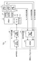
- FIG. 1 is a block diagram showing a configuration of a motor control system according to an embodiment.
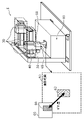
- FIG. 2 is a perspective view of a production apparatus to which the motor control system according to the embodiment is applied.
- FIG. 3 is a diagram showing an example of sensor information output from the position sensor and the acceleration sensor according to the embodiment.
- FIG. 4 is a flowchart showing a first example of the operation of the abnormality determination device according to the embodiment.
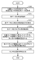
- FIG. 5 is a flowchart showing a second example of the operation of the abnormality determination device according to the embodiment.
- FIG. 6 is a flowchart showing a third example of the operation of the abnormality determination device according to the embodiment.
- FIG. 7 is a block diagram showing a configuration of a motor control system according to a modified example of the embodiment.
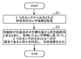
- FIG. 8 is a flowchart showing an example of an abnormality determination method according to another embodiment.
- sensors such as an accelerometer and a camera may be installed in the equipment to control the positioning of moving parts.
- sensors such as an accelerometer and a camera may be installed in the equipment to control the positioning of moving parts.
- the sensor information of any of these sensors may become an abnormal value and proper positioning control may not be possible.
- the inventors have come up with the following abnormality determination device and the like that can easily determine the abnormality of the sensor.
- the abnormality determination device includes a sensor information acquisition unit that acquires time-series sensor information output from two sensors that detect different physical quantities for a movable unit that is positioned and controlled, and the movable unit that positions the movable unit. It is provided with a determination unit that determines whether or not at least one of the two sensors is abnormal based on the acquired sensor information when the target position is within a predetermined range, and outputs a determination result.
- the abnormality determination device automatically determines whether or not at least one of the two sensors that detect different physical quantities is abnormal, it is possible to easily determine the abnormality of the sensor.
- the two sensors may include an acceleration sensor that detects and outputs the acceleration of the movable portion and a position sensor that detects and outputs the position deviation of the movable portion from the target position.
- the two sensors may be an acceleration sensor and a position sensor.
- the acceleration sensor may be fixed to the movable portion, and the position sensor may be fixed to the movable portion or an object placed at the target position different from the movable portion.
- the sensor fixed to the movable part tends to loosen when fastened to the movable part due to vibration during movement, etc., but in the present disclosure, since it is possible to easily determine the abnormality of the sensor, the sensor and the movable part The looseness of the fastening can be easily determined.
- the determination unit may determine whether or not it is abnormal by comparing the fluctuation indicated by at least one of the sensor information output from the two sensors with the first threshold value.
- the fluctuation indicated by the sensor information of the sensor with the loose fastening may be abnormal (for example, the fluctuation may be steep). Therefore, it can be determined that the sensor with steep fluctuations indicated by the sensor information is abnormal.
- the determination unit may determine whether or not it is abnormal by comparing the physical quantities indicated by the sensor information output from the two sensors.
- the determination unit performs a process of matching the dimension of the change with respect to time, the time derivative of the change, and the second derivative of the change with respect to the sensor information output from the two sensors. Later, the comparison may be made.
- the determination unit may determine whether or not it is abnormal by comparing the physical quantity indicated by the sensor information output from the two sensors with the second threshold value.
- the fastening of at least one of the two sensors is loose, the physical quantity indicated by the sensor information of the sensor with the loose fastening may be abnormal (for example, it may be a large value). Therefore, it can be determined that the sensor whose physical quantity indicated by the sensor information is abnormal is abnormal.
- the determination unit performs frequency analysis on the sensor information output from the two sensors and compares the obtained spectrum with the second threshold value to determine whether or not the sensor information is abnormal. You may judge.
- the motor control device is a motor control device that controls the positioning of a movable portion by driving a motor, and includes the above-mentioned abnormality determination device.
- the abnormality determination method is an abnormality determination method executed by a computer, and acquires time-series sensor information output from two sensors that detect different physical quantities for movable parts whose positioning is controlled. Based on the sensor information acquisition step to be performed and the sensor information acquired when the movable portion is within a predetermined range from the target position for positioning, it is determined whether or not at least one of the two sensors is abnormal. , A determination step for outputting a determination result is included.
- the program according to one aspect of the present disclosure is a program that causes a computer to execute the steps included in the above-mentioned abnormality determination method.
- This motor control system is a system that controls a motor to move a movable part connected to the motor to a target position.
- This motor control system may be, for example, a production device in which components are mounted on a substrate.
- FIG. 1 is a block diagram showing a configuration of a motor control system 10 according to an embodiment.
- the motor control system 10 includes a motor control device 20, an abnormality determination device 25, a motor 30, an encoder 31, a movable portion 40, an acceleration sensor 50, a position sensor 60, and a joint portion. 51 and 61 are provided.
- the motor control device 20 shows an example including the abnormality determination device 25.
- the motor 30 is driven by a drive signal output from the motor control device 20.
- the motor 30 will be described as a rotary motor.
- the motor 30 is not necessarily limited to the rotary motor, and may be, for example, a linear motor.
- the drive signal is, for example, a current for rotating the motor 30.
- the encoder 31 detects the position of the motor 30 and outputs an encoder signal indicating the detected position of the motor 30 to the motor control device 20.
- the movable portion 40 is connected to the motor 30.
- the motor control system 10 is a production device (parts mounting machine or the like) for mounting parts on a substrate
- the movable portion 40 is a header for transporting the parts to a mounting position.
- the acceleration sensor 50 is fixed to the movable portion 40, detects the acceleration of the movable portion 40, and outputs sensor information indicating the time-series acceleration of the detected movable portion 40 to the motor control device 20 (specifically, the abnormality determination device 25). ). Acceleration is an example of a physical quantity related to the movable portion 40 detected by the sensor. A speed sensor, a gyro sensor, or the like may be fixed to the movable portion 40 instead of the acceleration sensor 50 or in addition to the acceleration sensor 50.
- the position sensor 60 is fixed to the movable portion 40, detects a position deviation (also referred to as a target position deviation) of the movable portion 40 with respect to the positioning target position 66 (details will be described later), and is a time series of the detected movable portion 40.
- the sensor information indicating the target position deviation is output to the motor control device 20 (specifically, the abnormality determination device 25).
- the target position deviation is an example of a physical quantity related to the movable portion 40 detected by the sensor.
- the position sensor 60 is, for example, an image pickup device (camera).
- the position sensor 60 may be fixed to an object placed at the target position 66 (for example, an object placed around the target position 66), which is different from the movable portion 40. As long as the movable portion 40 is fixed at a position where it can be detected that the movable portion 40 is within a predetermined range from the target position 66, the target to which the position sensor 60 is fixed is not limited.
- the joint portion 51 is a fastening member for fixing the acceleration sensor 50 to the movable portion 40.
- aging may cause loosening in the fastening between the acceleration sensor 50 and the movable portion 40.
- loosening is likely to occur in the fastening between the acceleration sensor 50 and the movable portion 40 due to vibration or the like accompanying the movement of the movable portion 40.
- the joint portion 61 is a fastening member for fixing the position sensor 60 to the movable portion 40.
- aging may cause loosening in the fastening between the position sensor 60 and the movable portion 40.
- loosening is likely to occur in the fastening between the position sensor 60 and the movable portion 40 due to vibration or the like accompanying the movement of the movable portion 40.
- the joint portion 61 becomes a fastening member for fixing the position sensor 60 to the object.
- aging may cause loosening in the fastening between the position sensor 60 and the object.
- the motor control device 20 is a device that controls the positioning of the movable portion 40 by driving the motor 30.
- the motor control device 20 includes a command acquisition unit 21 and a position control unit 22 as components for controlling the positioning of the movable unit 40.
- the abnormality determination device 25 may be provided separately from the motor control device 20.
- the abnormality determination device 25 is a device for determining an abnormality of two sensors (here, an acceleration sensor 50 and a position sensor 60).
- the abnormality determination device 25 includes a sensor information acquisition unit 23 and a determination unit 24 as components for determining an abnormality of the two sensors.
- the motor control device 20 and the abnormality determination device 25 are computers including a processor, a memory, and the like.
- the memory is a ROM (Read Only Memory), a RAM (Random Access Memory), or the like, and can store a program executed by the processor.
- the command acquisition unit 21, the position control unit 22, the sensor information acquisition unit 23, and the determination unit 24 are realized by a processor that executes a program stored in the memory.
- the command acquisition unit 21 acquires an operation command.
- the operation command includes a command signal for setting the position of the movable portion 40 to the target position.
- the command signal may be, for example, a position command signal indicating a position command for setting the position of the movable portion 40 to the target position, or a speed command indicating a speed command for setting the position of the movable portion 40 to the target position. It may be a signal, it may be an acceleration command signal indicating an acceleration command for setting the position of the movable portion 40 to the target position, or it may be a torque command indicating the position of the movable portion 40 to be the target position. It may be a torque command signal.
- the position control unit 22 is movable based on the operation command acquired by the command acquisition unit 21, the encoder signal acquired by the encoder 31, the sensor information acquired by the acceleration sensor 50, and the sensor information acquired by the position sensor 60.
- a drive signal for driving the motor 30 is generated so as to move the unit 40 to the target position, and the generated drive signal is output to the motor 30.
- the position control unit 22 generates a drive signal by performing feedback control for feeding back the sensor information acquired by the sensor information acquisition unit 23 in response to the operation command acquired by the command acquisition unit 21.
- the sensor information acquisition unit 23 acquires time-series sensor information output from two sensors (here, the acceleration sensor 50 and the position sensor 60) that detect different physical quantities for the movable unit 40 whose positioning is controlled. Specifically, the sensor information acquisition unit 23 acquires sensor information indicating the time-series acceleration of the movable unit 40 from the acceleration sensor 50, and sensor information indicating the time-series target position deviation of the movable unit 40 from the position sensor 60. To get.
- the determination unit 24 determines whether or not at least one of the two sensors is abnormal based on the acquired sensor information when the movable unit 40 is within a predetermined range from the positioning target position 66, and the determination result Is output. For example, as a determination result, the acceleration sensor 50 is abnormal, the position sensor 60 is abnormal, both the acceleration sensor 50 and the position sensor 60 are abnormal, or the acceleration sensor 50 and the position sensor 60 are abnormal. It is not known which is abnormal, but at least one of them is output.
- the determination unit 24 determines whether or not it is abnormal by comparing the fluctuation indicated by at least one of the sensor information output from the two sensors with the first threshold value.
- the first threshold value is set in advance according to the fluctuation indicated by the sensor information output from the normal acceleration sensor 50 and the normal position sensor 60.
- the first threshold value is set to a value larger than the maximum fluctuation or the maximum fluctuation indicated by the sensor information output from the normal acceleration sensor 50 and the normal position sensor 60.
- the fluctuation indicated by the sensor information output from the abnormal sensor becomes a steep fluctuation exceeding the first threshold value, and can be determined to be abnormal.
- the determination unit 24 determines whether or not it is abnormal by comparing the physical quantities indicated by the sensor information output from the two sensors. However, since physical quantities of different dimensions may not be accurately compared with each other, the determination unit 24 performs the above comparison after processing the sensor information output from the two sensors to match the dimensions. May be good.
- the dimension is, for example, either a change with respect to time, the time derivative of the change, or the second derivative of the change.
- the sensor information output from the acceleration sensor 50 is double integrated.
- the dimensions can be matched.
- the sensor information output from the acceleration sensor 50 is used. The dimensions can be matched by integrating and differentiating the sensor information output from the position sensor 60.
- the sensor information output from the position sensor 60 is used.
- the dimensions can be matched.
- the above comparison may be performed after the sensor information output from the position sensor 60 and the sensor information output from the acceleration sensor 50 are processed to match the dimensions with the lower dimensional dimensions.
- the determination unit 24 determines whether or not it is abnormal by comparing the physical quantity indicated by the sensor information output from the two sensors with the second threshold value.
- the second threshold value is set in advance according to the physical quantity indicated by the sensor information output from the normal acceleration sensor 50 and the normal position sensor 60.
- the second threshold value is set to a value larger than the maximum physical quantity indicated by the sensor information output from the normal acceleration sensor 50 and the normal position sensor 60.
- the determination unit 24 determines whether or not the sensor information is abnormal by performing frequency analysis on the sensor information output from the two sensors and comparing the obtained spectrum with the second threshold value. May be good. When there is an abnormality in the sensor, the frequency component of a specific frequency band can have an abnormal value. Therefore, by performing frequency analysis, it is possible to accurately determine whether or not the sensor is abnormal.
- the determination unit 24 may notify the outside to that effect.
- FIG. 2 is a perspective view of a production apparatus (parts mounting machine 5) to which the motor control system 10 according to the embodiment is applied. Note that FIG. 2 also shows a top view of the periphery of the photographing range 63 of the position sensor 60 when the position sensor 60, which is an image pickup device, is near the target position 66. As shown in FIG. 2, when the production apparatus to which the motor control system 10 is applied is the component mounting machine 5, the acceleration sensor 50 and the position sensor 60 are fixed to the header as the movable portion 40 whose position is controlled by the motor 30. ing.
- the target position 66 is a position on the substrate 65 on which the parts transported by the movable portion 40 are mounted.
- the time when the movable portion 40 is within a predetermined range from the target position 66 for positioning is, for example, when the target position 66 is included in the shooting range 63 of the position sensor 60.
- the position sensor 60 is fixed to an object placed at the target position 66, when the movable portion 40 is within a predetermined range from the positioning target position 66, for example, the shooting range 63 of the position sensor 60 This is when the movable portion 40 is included inside.
- the determination unit 24 starts the determination, so that the determination unit 24 can start the determination.
- the processing load can be reduced.
- the movable portion 40 is away from the positioning target position 66, the movable portion 40 is not shown in the position sensor 60 (imaging device), and the sensor information output from the position sensor 60 includes the target of the movable portion 40. This is because it does not contain information about the position deviation. That is, even if the sensor information that does not include the information about the target position deviation of the movable portion 40 is used, it cannot be determined whether or not the position sensor 60 is abnormal, and the determination process may be wasted. be.
- the distance from the marker 62 provided in the shooting range 63 of the position sensor 60 (for example, the marker indicating the center of the shooting range 63) to the target position 66 captured in the shooting range 63 is the target position deviation of the movable portion 40. It becomes the information of. This distance becomes the amount of deviation of the movable portion 40 from the target position 66, and the movable portion 40 is such that the deviation amount becomes approximately 0, that is, the marker 62 and the target position 66 overlap in the photographing range 63. Positioning is controlled.
- FIG. 3 is a diagram showing an example of sensor information output from the position sensor 60 and the acceleration sensor 50 according to the embodiment.
- (A1) to (a3) of FIG. 3 show the sensor information output from the position sensor 60
- (b1) to (b3) of FIG. 3 show the sensor information output from the acceleration sensor 50.
- FIGS. 3A2 and 3B are sensor information when the position sensor 60 and the acceleration sensor 50 are normal, respectively.
- the position sensor 60 is abnormal (specifically, there is an abnormality in the fastening between the position sensor 60 and the movable portion 40), and the acceleration sensor 50 is normal. This is the sensor information of the case.
- the broken line in (a2) of FIG. 3 it can be seen that the abnormality of the position sensor 60 appears in the sensor information.
- (a3) and (b3) in FIG. 3 are spectra obtained by frequency analysis of the sensor information shown in FIGS. 3 (a2) and (b2). As shown in (a3) and (b3) of FIG.
- the frequency of a specific frequency (for example, the frequency of the portion surrounded by the broken line of (a3) and (b3) of FIG. 3 is obtained by frequency analysis of the sensor information. ), It can be seen that there is a remarkable difference between the spectrum of the abnormal position sensor 60 and the spectrum of the normal acceleration sensor 50.
- the determination unit 24 performs frequency analysis on such sensor information and sensor information, and determines whether or not at least one of the two sensors is abnormal using the obtained spectrum.
- FIG. 4 is a flowchart showing a first example of the operation of the abnormality determination device 25 according to the embodiment.
- the sensor information acquisition unit 23 acquires the time-series data of the position sensor 60 and the time-series data of the acceleration sensor 50 (step S10).
- the determination unit 24 aligns the dimensions of each data (step S11). As described above, the determination unit 24 makes the time series data output from the two sensors match the dimension with respect to one of the dimensions of the change with respect to time, the time derivative of the change, and the second derivative of the change. Perform processing.
- the determination unit 24 determines whether or not there is an abnormality in the sensor by calculating the difference value of each dimension-matched data (step S12) and determining whether or not the difference value exceeds the threshold value. (Step S13).
- the threshold value is set to a value larger than the maximum difference value of each data of the normal acceleration sensor 50 and the normal position sensor 60 whose dimensions are matched. If there is an abnormality in either of the two sensors, the time series data of either of the two sensors will be an abnormal value and the difference value can be large, so if the difference value exceeds the threshold value, two It can be determined that there is an abnormality in any of the sensors.
- the determination unit 24 outputs the presence / absence of an abnormality in the sensor (step S14).
- FIG. 5 is a flowchart showing a second example of the operation of the abnormality determination device 25 according to the embodiment.
- the sensor information acquisition unit 23 acquires the time-series data of the position sensor 60 and the time-series data of the acceleration sensor 50 (step S20).
- the determination unit 24 removes a specific frequency component from each data (step S21). For example, unnecessary frequency components such as high frequency components are removed.
- the determination unit 24 analyzes each data by frequency (step S22). For example, the determination unit 24 performs FFT (Fast Fourier Transform) analysis. This makes it possible to determine the presence or absence of anomalies using the spectrum obtained by frequency analysis of each data.
- FFT Fast Fourier Transform
- the determination unit 24 sets different thresholds for the spectrum calculated from the sensor information of the position sensor 60 and the spectrum calculated from the sensor information of the acceleration sensor 50 (step S23), and whether each spectrum exceeds the threshold.
- the sensor By determining whether or not the sensor is abnormal, it is determined whether or not there is an abnormality in the sensor (step S24). Since the physical quantity (position) indicated by the sensor information of the position sensor 60 and the physical quantity (acceleration) indicated by the sensor information of the acceleration sensor 50 have different dimensions and it is difficult to set the same threshold value, different threshold values are set. For example, each threshold value is set to a value larger than the maximum value of the frequency component of a specific frequency band in the spectrum calculated from the sensor information output from the normal acceleration sensor 50 and the normal position sensor 60.
- the frequency component of a specific frequency band becomes an abnormal value and the value can be large. Therefore, when the value of the frequency component of the specific frequency band exceeds the threshold value. Can determine that there is an abnormality in the sensor.
- the determination unit 24 outputs the presence / absence of an abnormality in the sensor (step S25).
- FIG. 6 is a flowchart showing a third example of the operation of the abnormality determination device 25 according to the embodiment.
- the sensor information acquisition unit 23 acquires the time-series data of the position sensor 60 and the time-series data of the acceleration sensor 50 (step S30).
- the determination unit 24 aligns the dimensions of each data (step S31). As described above, the determination unit 24 makes the time series data output from the two sensors match the dimension with respect to one of the dimensions of the change with respect to time, the time derivative of the change, and the second derivative of the change. Perform processing.
- the determination unit 24 removes a specific frequency component from each dimension-matched data (step S32). For example, unnecessary frequency components such as high frequency components are removed.
- the determination unit 24 analyzes each data by frequency (step S33). For example, the determination unit 24 performs FFT analysis. This makes it possible to determine the presence or absence of anomalies using the spectrum obtained by frequency analysis of each data.
- step S32 may be performed after the process in step S33 is performed.
- the determination unit 24 sets the same threshold value for both the spectrum calculated from the sensor information of the position sensor 60 and the spectrum calculated from the sensor information of the acceleration sensor 50 (step S34), and each spectrum exceeds the threshold value.
- the same threshold value can be set for both. For example, the threshold is set to a value larger than the maximum value of the frequency component in a specific frequency band in the spectrum calculated from the dimensionally matched sensor information output from the normal acceleration sensor 50 and the normal position sensor 60. Set.
- the frequency component of a specific frequency band becomes an abnormal value and the value can be large. Therefore, when the value of the frequency component of the specific frequency band exceeds the threshold value. Can determine that there is an abnormality in the sensor.
- the determination unit 24 outputs the presence / absence of an abnormality in the sensor (step S36).
- the abnormality determination device 25 automatically determines whether or not at least one of the two sensors (for example, the position sensor 60 and the acceleration sensor 50) that detect different physical quantities is abnormal, the sensor of the sensor. Abnormality can be easily determined. Further, by performing a process of matching the dimensions of the information output from the two sensors and performing a frequency analysis, it is possible to facilitate the determination of the abnormality.
- the movable portion 40 may have three or more sensors for detecting the physical quantity. This will be described with reference to FIG.
- FIG. 7 is a block diagram showing a configuration of a motor control system 10a according to a modified example of the embodiment.
- the motor control system 10a is different from the motor control system 10 according to the embodiment in that the acceleration sensor 52 and the joint portion 53 are further provided. Since other points are the same as those in the embodiment, the description thereof will be omitted.
- the acceleration sensor 52 is fixed to the movable portion 40, detects the acceleration of the movable portion 40, and obtains sensor information indicating the time-series acceleration of the detected movable portion 40 in the motor control device 20 (specifically, the abnormality determination device 25). ).
- the acceleration sensor 50 is a sensor that detects the acceleration of the movable portion 40 in the x-axis direction
- the acceleration sensor 52 is the movable portion 40. It is a sensor that detects acceleration in the y-axis direction.
- the joint portion 53 is a fastening member for fixing the acceleration sensor 52 to the movable portion 40.
- aging may cause loosening in the fastening between the acceleration sensor 52 and the movable portion 40.
- loosening is likely to occur in the fastening between the acceleration sensor 52 and the movable portion 40 due to vibration or the like accompanying the movement of the movable portion 40.
- the sensor information acquisition unit 23 acquires time-series sensor information output from three or more sensors, and the determination unit 24 receives when the movable unit 40 is within a predetermined range from the positioning target position 66. , It may be determined whether or not at least one of the three or more sensors is abnormal based on the acquired sensor information, and the determination result may be output.
- the present disclosure can be realized not only as an abnormality determination device 25 and a motor control device 20, but also as an abnormality determination method including steps (processes) performed by the components constituting the abnormality determination device 25.
- FIG. 8 is a flowchart showing an example of an abnormality determination method according to another embodiment.
- the abnormality determination method is a method executed by a computer (for example, an abnormality determination device 25), and as shown in FIG. 8, a time series output from two sensors that detect different physical quantities for a movable part whose position is controlled. At least one of the two sensors is abnormal based on the sensor information acquisition step (step S1) for acquiring the sensor information of the above and the acquired sensor information when the movable part is within a predetermined range from the target position of positioning. It includes a determination step (step S2) in which it is determined whether or not it is, and the determination result is output.
- the present disclosure can be realized as a program for causing a processor to execute a step included in an abnormality determination method.
- the present disclosure can be realized as a non-temporary computer-readable recording medium such as a CD-ROM in which the program is recorded.
- each step is executed by executing the program using hardware resources such as a computer CPU, memory, and input / output circuit. .. That is, each step is executed by the CPU acquiring data from the memory or the input / output circuit or the like and performing an operation, or outputting the operation result to the memory or the input / output circuit or the like.
- hardware resources such as a computer CPU, memory, and input / output circuit. .. That is, each step is executed by the CPU acquiring data from the memory or the input / output circuit or the like and performing an operation, or outputting the operation result to the memory or the input / output circuit or the like.
- each component included in the abnormality determination device 25 and the motor control device 20 is realized by being configured with dedicated hardware or by executing a software program suitable for each component. You may.
- Each component may be realized by a program execution unit such as a CPU or a processor reading and executing a software program recorded on a recording medium such as a hard disk or a semiconductor memory.
- a part or all of the functions of the abnormality determination device 25 and the motor control device 20 according to the above embodiment are typically realized as an LSI which is an integrated circuit. These may be individually integrated into one chip, or may be integrated into one chip so as to include a part or all of them. Further, the integrated circuit is not limited to the LSI, and may be realized by a dedicated circuit or a general-purpose processor. An FPGA (Field Programmable Gate Array) that can be programmed after the LSI is manufactured, or a reconfigurable processor that can reconfigure the connection and settings of the circuit cells inside the LSI may be used.
- FPGA Field Programmable Gate Array
- the present disclosure can be widely used in a system or the like in which a movable part is positioned and controlled by a motor.
Landscapes
- Physics & Mathematics (AREA)
- General Physics & Mathematics (AREA)
- Engineering & Computer Science (AREA)
- Human Computer Interaction (AREA)
- Manufacturing & Machinery (AREA)
- Automation & Control Theory (AREA)
- Testing And Monitoring For Control Systems (AREA)
- Control Of Electric Motors In General (AREA)
Priority Applications (4)
| Application Number | Priority Date | Filing Date | Title |
|---|---|---|---|
| US18/248,468 US20230366932A1 (en) | 2020-12-23 | 2021-12-23 | Anomaly determining device, motor control device, anomaly determining method, and recording medium |
| EP21910941.0A EP4270777A4 (en) | 2020-12-23 | 2021-12-23 | Abnormality determining device, motor control device, abnormality determining method, and program |
| JP2022571609A JPWO2022138801A1 (https=) | 2020-12-23 | 2021-12-23 | |
| CN202180069713.1A CN116508254A (zh) | 2020-12-23 | 2021-12-23 | 异常判定装置、马达控制装置、异常判定方法及程序 |
Applications Claiming Priority (2)
| Application Number | Priority Date | Filing Date | Title |
|---|---|---|---|
| JP2020213145 | 2020-12-23 | ||
| JP2020-213145 | 2020-12-23 |
Publications (1)
| Publication Number | Publication Date |
|---|---|
| WO2022138801A1 true WO2022138801A1 (ja) | 2022-06-30 |
Family
ID=82159830
Family Applications (1)
| Application Number | Title | Priority Date | Filing Date |
|---|---|---|---|
| PCT/JP2021/047801 Ceased WO2022138801A1 (ja) | 2020-12-23 | 2021-12-23 | 異常判定装置、モータ制御装置、異常判定方法およびプログラム |
Country Status (5)
| Country | Link |
|---|---|
| US (1) | US20230366932A1 (https=) |
| EP (1) | EP4270777A4 (https=) |
| JP (1) | JPWO2022138801A1 (https=) |
| CN (1) | CN116508254A (https=) |
| WO (1) | WO2022138801A1 (https=) |
Families Citing this family (1)
| Publication number | Priority date | Publication date | Assignee | Title |
|---|---|---|---|---|
| JP7784627B2 (ja) * | 2020-12-23 | 2025-12-12 | パナソニックIpマネジメント株式会社 | 振動情報算出装置、振動情報算出方法、および、プログラム |
Citations (3)
| Publication number | Priority date | Publication date | Assignee | Title |
|---|---|---|---|---|
| JPH05229795A (ja) * | 1992-02-20 | 1993-09-07 | Toshiba Corp | 負荷平衡装置 |
| JP2005267138A (ja) | 2004-03-18 | 2005-09-29 | Yaskawa Electric Corp | 作業機械及びその位置補正方法 |
| WO2013175553A1 (ja) * | 2012-05-21 | 2013-11-28 | 株式会社安川電機 | ロボット |
Family Cites Families (3)
| Publication number | Priority date | Publication date | Assignee | Title |
|---|---|---|---|---|
| JP2006155180A (ja) * | 2004-11-29 | 2006-06-15 | Fanuc Ltd | 駆動制御装置 |
| JP5388823B2 (ja) * | 2009-12-02 | 2014-01-15 | 三菱電機株式会社 | 軌跡測定装置 |
| JP6069935B2 (ja) * | 2012-08-01 | 2017-02-01 | 富士通株式会社 | 故障診断支援装置、故障診断支援方法、および故障診断支援プログラム |
-
2021
- 2021-12-23 JP JP2022571609A patent/JPWO2022138801A1/ja active Pending
- 2021-12-23 CN CN202180069713.1A patent/CN116508254A/zh active Pending
- 2021-12-23 US US18/248,468 patent/US20230366932A1/en not_active Abandoned
- 2021-12-23 WO PCT/JP2021/047801 patent/WO2022138801A1/ja not_active Ceased
- 2021-12-23 EP EP21910941.0A patent/EP4270777A4/en not_active Withdrawn
Patent Citations (3)
| Publication number | Priority date | Publication date | Assignee | Title |
|---|---|---|---|---|
| JPH05229795A (ja) * | 1992-02-20 | 1993-09-07 | Toshiba Corp | 負荷平衡装置 |
| JP2005267138A (ja) | 2004-03-18 | 2005-09-29 | Yaskawa Electric Corp | 作業機械及びその位置補正方法 |
| WO2013175553A1 (ja) * | 2012-05-21 | 2013-11-28 | 株式会社安川電機 | ロボット |
Non-Patent Citations (1)
| Title |
|---|
| See also references of EP4270777A4 |
Also Published As
| Publication number | Publication date |
|---|---|
| US20230366932A1 (en) | 2023-11-16 |
| EP4270777A1 (en) | 2023-11-01 |
| EP4270777A4 (en) | 2024-06-05 |
| CN116508254A (zh) | 2023-07-28 |
| JPWO2022138801A1 (https=) | 2022-06-30 |
Similar Documents
| Publication | Publication Date | Title |
|---|---|---|
| US20160279794A1 (en) | Robot controller capable of performing fault diagnosis of robot | |
| US8378615B2 (en) | Motor controller | |
| TWI678065B (zh) | 馬達控制裝置 | |
| JP7000135B2 (ja) | 送り軸の異常診断方法及び異常診断装置 | |
| US10493576B2 (en) | Servo control device, spindle failure detection method using servo control device, and non-transitory computer readable medium encoded with computer program | |
| US20060158143A1 (en) | Controller | |
| WO2019239832A1 (ja) | 異常検知システム、設定ツール装置、コントローラ、異常定義情報のデータ構造、および異常対応ファンクションブロック | |
| WO2022138801A1 (ja) | 異常判定装置、モータ制御装置、異常判定方法およびプログラム | |
| KR20220159485A (ko) | 기기 상태 감시 장치 및 기기 상태 감시 방법 | |
| JP2020134479A (ja) | 異常検出方法および異常検出装置 | |
| CN112775719B (zh) | 进给轴装置的异常诊断方法和异常诊断装置 | |
| JP6730350B2 (ja) | 制御装置 | |
| US20150145460A1 (en) | Motor controller having abnormality detection function of power transmission unit between motor and main shaft | |
| CN109643113B (zh) | 故障诊断装置及故障诊断方法 | |
| TWI727663B (zh) | 處理資訊管理系統及管理處理資訊之方法 | |
| JP4285057B2 (ja) | サーボ制御装置 | |
| JP6101931B2 (ja) | モータ駆動装置 | |
| JPH11248528A (ja) | 異常振動検出装置 | |
| WO2021048968A1 (ja) | 劣化量検出装置、劣化量検出方法および劣化予測システム | |
| US20240198473A1 (en) | Vibration detection device | |
| JP7127292B2 (ja) | センサユニット、制御方法、プログラム、および記録媒体 | |
| JP7021656B2 (ja) | 情報処理装置、情報処理方法、及び情報処理プログラム | |
| JP2019192161A (ja) | 画像管理装置 | |
| WO2018083746A1 (ja) | 設備診断装置および設備診断方法 | |
| JP7784627B2 (ja) | 振動情報算出装置、振動情報算出方法、および、プログラム |
Legal Events
| Date | Code | Title | Description |
|---|---|---|---|
| 121 | Ep: the epo has been informed by wipo that ep was designated in this application |
Ref document number: 21910941 Country of ref document: EP Kind code of ref document: A1 |
|
| ENP | Entry into the national phase |
Ref document number: 2022571609 Country of ref document: JP Kind code of ref document: A |
|
| WWE | Wipo information: entry into national phase |
Ref document number: 202180069713.1 Country of ref document: CN |
|
| NENP | Non-entry into the national phase |
Ref country code: DE |
|
| ENP | Entry into the national phase |
Ref document number: 2021910941 Country of ref document: EP Effective date: 20230724 |
|
| WWW | Wipo information: withdrawn in national office |
Ref document number: 2021910941 Country of ref document: EP |