WO2022138657A1 - 医療機器 - Google Patents
医療機器 Download PDFInfo
- Publication number
- WO2022138657A1 WO2022138657A1 PCT/JP2021/047374 JP2021047374W WO2022138657A1 WO 2022138657 A1 WO2022138657 A1 WO 2022138657A1 JP 2021047374 W JP2021047374 W JP 2021047374W WO 2022138657 A1 WO2022138657 A1 WO 2022138657A1
- Authority
- WO
- WIPO (PCT)
- Prior art keywords
- ultraviolet
- sterilization
- uvx
- radiation
- irradiation
- Prior art date
- Legal status (The legal status is an assumption and is not a legal conclusion. Google has not performed a legal analysis and makes no representation as to the accuracy of the status listed.)
- Ceased
Links
Images











Classifications
-
- A—HUMAN NECESSITIES
- A61—MEDICAL OR VETERINARY SCIENCE; HYGIENE
- A61B—DIAGNOSIS; SURGERY; IDENTIFICATION
- A61B6/00—Apparatus or devices for radiation diagnosis; Apparatus or devices for radiation diagnosis combined with radiation therapy equipment
-
- A—HUMAN NECESSITIES
- A61—MEDICAL OR VETERINARY SCIENCE; HYGIENE
- A61L—METHODS OR APPARATUS FOR STERILISING MATERIALS OR OBJECTS IN GENERAL; DISINFECTION, STERILISATION OR DEODORISATION OF AIR; CHEMICAL ASPECTS OF BANDAGES, DRESSINGS, ABSORBENT PADS OR SURGICAL ARTICLES; MATERIALS FOR BANDAGES, DRESSINGS, ABSORBENT PADS OR SURGICAL ARTICLES
- A61L2/00—Disinfection or sterilisation of materials or objects, in general; Accessories therefor
- A61L2/02—Disinfection or sterilisation of materials or objects, in general; Accessories therefor using physical processes
- A61L2/08—Radiation
- A61L2/10—Ultraviolet [UV] radiation
Definitions
- the technology disclosed here relates to medical devices.
- Medical devices that are used repeatedly are not a little contaminated by the adhesion of bacteria and / or viruses due to contact with people such as patients or operators. Therefore, conventionally, for example, as in Japanese Patent Application Laid-Open No. 2013-248124, a technique for sterilizing a medical device that is repeatedly used by irradiating it with ultraviolet rays has been proposed. Note that sterilization means inactivating bacteria and / or viruses.
- Japanese Patent Application Laid-Open No. 2013-248124 describes an electronic cassette used for radiography as a medical device that is repeatedly used.
- an ultraviolet source is provided inside a holder for accommodating an electronic cassette, which is provided in a mobile radiation generator that performs radiography (so-called round-trip radiography) while going around a hospital room, and is accommodated in the holder.
- the electronic cassette is irradiated with ultraviolet rays.
- One embodiment according to the technique of the present disclosure is a medical device capable of visually clarifying whether or not sterilizing ultraviolet rays have been irradiated and whether or not the bactericidal effect of the sterilizing ultraviolet rays is sustained. I will provide a.
- the medical device of the present disclosure is provided on the outer peripheral surface and at least a part of the outer peripheral surface, starts emitting light by irradiation with ultraviolet rays for sterilization, and dims after the irradiation of ultraviolet rays for sterilization is stopped, thereby for sterilization. It comprises a illuminant that emits visible light that indicates whether or not it has been irradiated with ultraviolet light and whether or not the effect of sterilization by the ultraviolet light for sterilization is sustained.
- the illuminant is extinct while dimming after the irradiation of ultraviolet rays for sterilization is stopped.
- the time from when the irradiation of the sterilizing ultraviolet rays is stopped until the light emitter is extinguished is shorter than the duration of the sterilizing effect of the sterilizing ultraviolet rays.
- the light emitter is preferably a paint applied to the outer peripheral surface.
- the light emitting body is preferably a seal that can be peelably attached to the outer peripheral surface.
- a recess is formed on the outer peripheral surface, and it is preferable that the light emitting body is fitted in the recess.
- an ultraviolet shielding member that shields the ultraviolet rays that sensitize the illuminant.
- the ultraviolet shielding member is preferably a seal that can be peelably attached to the outer peripheral surface.
- the ultraviolet shielding member is preferably a shutter that moves between a first position that covers the light emitting body and a second position that exposes the light emitting body.
- the illuminant is provided outside the area to be irradiated with radiation.
- the detection panel that detects radiation and outputs a radiation image is an electronic cassette built in a portable housing.
- the patient has a holder for accommodating a cassette for radiography, and is a standing or lying position imaging table for photographing a patient in a standing or lying position.
- the ultraviolet source is irradiated with ultraviolet rays for sterilization, and the elapsed time from the start of irradiation of the ultraviolet rays for sterilization is set to a preset time.
- the mammography apparatus 10 takes the breast M of the patient P as a subject.
- the mammography apparatus 10 irradiates the breast M with radiation R such as X-rays and ⁇ -rays, and acquires a radiographic image of the breast M.
- the mammography apparatus 10 is an example of a "medical device" according to the technique of the present disclosure.
- the mammography apparatus 10 includes an apparatus main body 11 and a control device 12.
- the device main body 11 is installed, for example, in a radiography room of a medical facility.
- the control device 12 is installed in, for example, a control room next to the radiography room.
- the control device 12 is, for example, a desktop personal computer.
- the control device 12 is communicably connected to an image database (hereinafter abbreviated as DB (Data Base)) server 14 via a network 13 such as a LAN (Local Area Network).
- DB Data Base
- the image DB server 14 is, for example, a PACS (Picture Archiving and Communication System) server, which receives a radiographic image from the mammography apparatus 10 and stores and manages the received radiographic image.
- PACS Picture Archiving and Communication System
- the terminal device 15 is also connected to the network 13.
- the terminal device 15 is, for example, a personal computer used by a doctor who performs a medical examination using a radiographic image.
- the terminal device 15 receives a radiation image from the image DB server 14, and displays the received radiation image on the display.
- the device main body 11 has a stand 20 and an arm 21.
- the stand 20 is composed of a pedestal 20A installed on the floor of the radiography room and a support column 20B extending in the height direction from the pedestal 20A.
- the arm 21 has a substantially C-shape when viewed from the side, and is connected to the support column 20B via the connecting portion 21A. With this connection portion 21A, the arm 21 can be moved in the height direction with respect to the support column 20B, and the height can be adjusted according to the height of the patient P. Further, the arm 21 can rotate around a rotation axis perpendicular to the support column 20B, penetrating the connection portion 21A.
- the arm 21 is composed of a radiation source accommodating portion 22, a photographing table 23, and a main body portion 24.
- the radiation source 25 is accommodated in the radiation source accommodating portion 22.
- Breast M is placed on the imaging table 23.
- the detection panel 26 is housed in the shooting table 23.
- the main body portion 24 integrally connects the radiation source accommodating portion 22 and the photographing table 23.
- the main body portion 24 holds the radiation source accommodating portion 22 and the photographing table 23 at positions facing each other.
- Handrails 27 on both sides of the main body 24 are provided so that the hand of the patient P can be grasped.
- An indirect lighting lamp 28 is attached to the main body portion 24.
- the indirect lighting lamp 28 irradiates the support column 20B with warm-colored dark indirect lighting light in order to alleviate the anxiety of the patient P.
- the indirect lighting lamp 28 may be attached to the outer surface and / or the inside of the support column 20B. In this case, the indirect illumination lamp 28 irradiates the indirect illumination light toward the main body portion 24.
- the radiation source 25 includes a radiation tube 29 and a housing 30 that houses the radiation tube 29.
- the inside of the housing 30 is filled with insulating oil.
- the radiation tube 29 irradiates the radiation R toward the breast M placed on the imaging table 23.
- the detection panel 26 detects the radiation R transmitted through the breast M and outputs a radiation image.
- the radiation tube 29 has a cathode and an anode.
- the cathode emits electrons.
- the anode emits radiation R when electrons collide.
- the cathode and anode are housed in a vacuum glass tube having a substantially cylindrical shape.
- the cathode is, for example, a cold cathode. More specifically, the cathode is a field emission type having an electron emission source that emits an electron beam toward the anode by utilizing the field emission phenomenon.
- the anode is a rotating anode that is rotated by a rotating mechanism. A fixed anode whose position is fixed without rotating may be used.
- the tube voltage from the tube voltage generator (not shown) is applied between the cathode and the anode.
- an electron beam is emitted from the cathode toward the anode.
- the radiation R is emitted from the point (focal point) of the anode where the electron beam collides. Radiation R is emitted to the outside through an irradiation window provided on the glass tube.
- An irradiation field limiting device 31 is provided between the radiation source accommodating portion 22 and the photographing table 23.
- the irradiation field limiting device 31 is also called a collimator, and defines the irradiation field of the radiation R to the photographing table 23.
- the irradiation field limiting device 31 is formed with an incident opening in which the radiation R from the radiation tube 29 is incident and an exit opening in which the radiation R is emitted.
- Four shielding plates are provided in the vicinity of the exit opening.
- the shielding plate is made of a material that shields radiation R, for example, lead.
- the shielding plate is arranged on each side of the quadrangle, in other words, is assembled in a checkered pattern, and forms a quadrangular irradiation opening through which the radiation R is transmitted.
- the irradiation field limiting device 31 changes the size of the irradiation aperture by changing the position of each shielding plate, thereby changing the irradiation field of the radiation R to the photographing table 23.
- An irradiation field lamp is provided in the irradiation field limiting device 31.
- the irradiation field lamp emits, for example, orange visible light.
- the visible light emitted from the irradiation field lamp is emitted toward the photographing table 23 through the exit opening as light representing the irradiation field.
- a filter for changing the radiation quality of the radiation R may be provided in the irradiation field limiting device 31.
- a face guard 32 is attached to the radiation source accommodating portion 22.
- the face guard 32 is formed or coated with a material that does not transmit radiation R to protect the face of patient P from radiation R.
- a compression plate 33 is attached between the shooting table 23 and the irradiation field limiting device 31.
- the compression plate 33 is made of a material that transmits radiation R.
- the compression plate 33 is arranged at a position facing the photographing table 23.
- the compression plate 33 can be moved in a direction toward the photographing table 23 and a direction away from the photographing table 23 according to the operation of the elevating switch (not shown).
- the compression plate 33 moves toward the imaging table 23, sandwiches the breast M with the imaging table 23, and presses the breast M.
- An ultraviolet source 34 is provided on the outer surface of the irradiation field limiting device 31 facing the compression plate 33. More specifically, the ultraviolet source 34 is provided on the outer surface of the irradiation field limiting device 31 on the back side of the face guard 32. As an example, as shown in FIG. 3, the ultraviolet source 34 applies ultraviolet UVX for sterilization having a center wavelength of 200 nm or more and 280 nm or less (for example, 254 nm or 222 nm) and a constant intensity to the face guard 32, the compression plate 33, and the like. Irradiate toward. As the ultraviolet source 34, an LED (Light Emitting Diode), an LD (Laser Diode), or the like can be adopted in addition to a general ultraviolet lamp using a quartz tube such as an excimer lamp.
- an LED Light Emitting Diode
- LD Laser Diode
- the face guard 32 and the compression plate 33 are made of a material that transmits ultraviolet rays UVX for sterilization.
- the material that transmits ultraviolet UVX for sterilization include the product name "Cytop (registered trademark)" manufactured by AGC Inc. Therefore, the ultraviolet UVX for sterilization enters the face guard 32 from the back surface 51 (see FIG. 6) of the face guard 32 and irradiates the surface 50 (see FIG. 6) of the face guard 32 facing the face of the patient P. do. Further, the ultraviolet UVX for sterilization enters the compression plate 33 from the back surface 58 (see FIG. 7) of the compression plate 33 and irradiates the surface 57 (see FIG. 7) of the compression plate 33 in contact with the breast M.
- the sterilizing ultraviolet UVX transmitted through the compression plate 33 irradiates the surface 46 (see FIG. 5) of the imaging table 23 on which the breast M is placed. That is, in this example, the photographing table 23, the face guard 32, and the compression plate 33 are mainly irradiated with ultraviolet UVX for sterilization.
- the ultraviolet source control unit 40 is connected to the ultraviolet source 34.
- the ultraviolet source control unit 40 controls the operation of the ultraviolet source 34.
- the ultraviolet source control unit 40 is constructed in the CPU (Central Processing Unit) of the control device 12, for example, by executing a program.
- a lighting instruction switch 41 is connected to the ultraviolet source control unit 40.
- the lighting instruction switch 41 is displayed as a GUI (Graphical User Interface) on the display of the control device 12, for example.
- the ultraviolet source control unit 40 When the lighting instruction switch 41 is operated by an operator such as a radiologist through the input device of the control device 12, the ultraviolet source control unit 40 outputs the lighting instruction signal LIS to the ultraviolet source 34. As a result, irradiation of ultraviolet UVX for sterilization by the ultraviolet source 34 is started.
- the ultraviolet source control unit 40 measures the elapsed time from the start of irradiation of ultraviolet UVX for sterilization. When the elapsed time reaches the preset set time TS, the ultraviolet source control unit 40 outputs the extinguishing instruction signal OIS. As a result, the irradiation of the ultraviolet UVX for sterilization by the ultraviolet source 34 is stopped. That is, when the lighting instruction switch 41 is operated, the ultraviolet source 34 emits ultraviolet UVX for sterilization during the set time TS.
- the set time TS is the irradiation time of ultraviolet UVX required for sterilizing bacteria and / or viruses.
- the set time TS varies depending on the intensity of ultraviolet UVX for sterilization, the type of bacteria and / or virus to be sterilized, and the like, but is generally several seconds to several tens of minutes. For example, it has been reported that the new coronavirus (SARS (Severe Acute Respiratory Syndrome) -CoV (Coronavirus) -2) is inactivated by irradiation with ultraviolet UVX for several seconds.
- SARS severe Acute Respiratory Syndrome
- -CoV Coronavirus
- the detection panel 26 has a rectangular detection surface 45.
- the detection surface 45 is a surface for detecting the radiation R transmitted through the breast M. More specifically, the detection surface 45 is a two-dimensional plane in which pixels that convert radiation R into an electric signal are two-dimensionally arranged.
- Such a detection panel 26 is called an FPD (Flat Panel Detector).
- the detection panel 26 has a scintillator that converts the radiation R into visible light, and may be an indirect conversion type that converts the visible light emitted by the scintillator into an electric signal, or a direct conversion type that directly converts the radiation R into an electric signal. ..
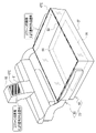
- the surface 46 of the photographing table 23 has a rectangular shape that is one size larger than the detection surface 45 of the detection panel 26.
- the surface 46 is irradiated with radiation R in the region IA corresponding to the detection surface 45.
- L-shaped light emitters 47A1 are provided along the shape of the corners.
- the illuminant 47A1 is provided outside the region IA.
- the light emitter 47A1 is a paint applied to the surface 46 by screen printing or the like.
- the surface 46 is an example of "at least a portion of the outer peripheral surface” according to the technique of the present disclosure.
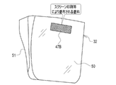
- a rectangular illuminant 47B is provided on the upper part of the surface 50 of the face guard 32.
- the light emitting body 47B is a paint applied to the surface 50 by screen printing or the like, similarly to the light emitting body 47A1.
- the surface 50 is an example of "at least a part of the outer peripheral surface” according to the technique of the present disclosure.
- the compression plate 33 has a box-shaped compression plate main body 55 and a mounting portion 56 that attaches the compression plate main body 55 to the main body portion 24 so as to be able to move up and down.
- the back surface 58 of the compression plate main body 55 is irradiated with radiation R in the region IA.
- Region IA is one size smaller than the back surface 58.
- a light emitting body 47C is provided on the opening edge surface 59 of the compression plate main body 55 and the surface 61 of the base 60 of the mounting portion 56.
- the light emitting body 47C is a paint applied to the opening edge surface 59 and the surface 61 by screen printing or the like, similarly to the light emitting bodies 47A1 and 47B.
- the opening edge 59 and the surface 61 are outside the region IA. That is, the light emitter 47C is provided outside the region IA.
- the opening edge surface 59 and the surface 61 are examples of "at least a part of the outer peripheral surface” according to the technique of the present disclosure.
- the light emitters 47A1 to 47C may be collectively referred to as a light emitter 47.
- the illuminant 47 starts emitting visible light by irradiation with ultraviolet UVX for sterilization.
- the light emitting body 47 reaches the maximum value (MAX) of visible light immediately after irradiation with ultraviolet UVX for sterilization.
- the light emitting body 47 maintains the maximum amount of light emitted while the ultraviolet UVX for sterilization is irradiated with TS for a set time.
- the amount of light emitted from the light emitting body 47 gradually decreases (dims) after the irradiation of ultraviolet UVX for sterilization is stopped.
- the light emitting body 47 is extinguished after a lapse of time TA from the stop of irradiation of the sterilizing ultraviolet UVX.
- the illuminant 47 indicates whether or not the ultraviolet rays UVX for sterilization are irradiated and whether or not the effect of sterilization by the ultraviolet rays UVX for sterilization is sustained.
- the effect of sterilization by ultraviolet UVX for sterilization gradually increases from the start of irradiation of ultraviolet UVX for sterilization, and when the elapsed time from the start of irradiation reaches the set time TS and the irradiation of ultraviolet UVX for sterilization is stopped. Reach the maximum value (MAX).
- MAX maximum value
- the effect of sterilization is maintained at the maximum value immediately after the irradiation of ultraviolet UVX for sterilization is stopped, but gradually decreases. Then, it disappears after a lapse of time TB from the stop of irradiation of ultraviolet UVX for sterilization.
- the inactivation rate of bacteria and / or virus in the region irradiated with ultraviolet UVX for sterilization is 99% or more, preferably 99.9%.
- the maximum value (MAX) value varies depending on the wavelength of ultraviolet UVX for sterilization, irradiation conditions such as intensity, types of bacteria and / or viruses, environmental conditions such as temperature and humidity, measurement method of inactivation rate, and the like. In some cases.
- the time TA from after the irradiation of the sterilizing ultraviolet UVX is stopped until the illuminant 47 is extinguished (hereinafter referred to as the quenching time of the illuminant 47) is shorter than the duration TB of the sterilizing effect of the sterilizing ultraviolet UVX.
- the duration of the sterilizing effect TB varies depending on the intensity of ultraviolet UVX for sterilization, the type of bacteria and / or virus to be sterilized, and the like, but is generally several minutes to several hours.
- the quenching time TA of the illuminant 47 is, for example, 70% to 80% of the duration TB of the bactericidal effect.
- the quenching time TA of the illuminant 47 is, for example, 7 to 8 minutes.
- the luminous body 47 includes a luminous paint manufactured by Asahipen Corporation (https://www.asahipen.jp/products/view/16813) and a transparent phosphorescent paint manufactured by Tateyama Kagaku Kogyo Co., Ltd. (https: // www). .tateyama.jp/product/dev_newmaterial.html) etc. can be adopted.
- the operator operates the lighting instruction switch 41 to instruct the lighting of the ultraviolet UVX for sterilization for the purpose of sterilizing the parts contaminated by the patient P such as the photographing table 23, the face guard 32, and the compression plate 33 (step). YES with ST100).
- the ultraviolet source control unit 40 outputs a lighting instruction signal LIS to the ultraviolet source 34, and the ultraviolet source 34 irradiates the ultraviolet UVX for sterilization (step ST110).
- visible light is emitted from the illuminant 47 irradiated with ultraviolet UVX for sterilization (step ST120).
- the ultraviolet source control unit 40 When the elapsed time from the start of irradiation of ultraviolet UVX for sterilization reaches the set time TS (YES in step ST130), the ultraviolet source control unit 40 outputs an extinguishing instruction signal OIS to the ultraviolet source 34. As a result, irradiation of ultraviolet UVX for sterilization is stopped (step ST140). Then, the light emitting body 47 is extinct while dimming (step ST150).
- the operator After irradiation with ultraviolet UVX for sterilization, the operator causes patient P to enter the radiography room. Then, the breast M of the patient P is placed on the imaging table 23 and compressed by the compression plate 33. The operator moves to the control room, sets the irradiation condition of the radiation R via the control device 12, and then inputs an instruction to start radiography. As a result, the radiation tube 29 is operated according to the irradiation conditions, and the radiation R is irradiated. The radiation R emitted from the radiation tube 29 is incident on the irradiation field limiting device 31. The radiation R incident on the irradiation field limiting device 31 passes through the irradiation opening formed by the shielding plate. This defines the irradiation field of radiation R.
- the irradiation field is defined by the irradiation field limiting device 31, and the radiation R irradiated to the breast M is detected by the detection panel 26. As a result, a radiation image is output from the detection panel 26. The radiation image is displayed on the display of the control device 12 after various image processings are performed by the control device 12.
- the mammography apparatus 10 is provided on the surface 46 of the imaging table 23, the surface 50 of the face guard 32, the opening edge surface 59 of the compression plate main body 55, and the surface 61 of the base 60 of the mounting portion 56.
- a light emitter 47 is provided. The illuminant 47 starts emitting light by irradiation with ultraviolet UVX for sterilization, and dims after the irradiation of ultraviolet UVX for sterilization is stopped to determine whether or not the ultraviolet UVX for sterilization has been irradiated and the ultraviolet UVX for sterilization. Shows whether the bactericidal effect of UV rays is sustained. Therefore, it is possible to visually clarify whether or not the sterilizing ultraviolet UVX has been irradiated and whether or not the sterilizing effect of the sterilizing ultraviolet UVX is sustained.
- the illuminant 47 is quenched while dimming after the irradiation of the sterilizing ultraviolet UVX is stopped. Therefore, regardless of the amount of light emitted, when visible light is emitted from the light emitting body 47, it can be clearly displayed that at least ultraviolet UVX for sterilization has been irradiated.
- the quenching time TA of the illuminant 47 is shorter than the duration TB of the effect of sterilization by the ultraviolet UVX for sterilization.
- the quenching time TA of the illuminant 47 is longer than the duration TB of the bactericidal effect, the illuminant 47 may emit visible light even though the bactericidal effect has disappeared. In this case, the operator may be misunderstood that the bactericidal effect is sustained. In the technique of the present disclosure, there is no such concern because the quenching time TA of the illuminant 47 is shorter than the duration TB of the bactericidal effect as described above.
- the light emitting body 47 includes the surface 46 of the photographing table 23, the surface 50 of the face guard 32, the opening edge surface 59 of the compression plate main body 55, and the surface 61 of the base 60 of the mounting portion 56. It is a paint applied to. Therefore, the light emitting body 47 can be provided relatively easily.
- the illuminant 47 is provided outside the region IA to which the radiation R is irradiated. Therefore, it is possible to prevent the image quality of the radiation image from being deteriorated by the light emitting body 47, such as the light emitting body 47 being reflected in the radiation image.
- the mammography apparatus 10 has a built-in detection panel 26 that detects radiation R and outputs a radiographic image, and sandwiches the breast M between the imaging table 23 on which the breast M of the patient P is placed and the imaging table 23. It has a compression plate 33 that compresses with.
- the photographing table 23 and the compression plate 33 are irradiated with ultraviolet UVX for sterilization. Further, a light emitting body 47 is provided on the photographing table 23 and the compression plate 33.
- the imaging table 23 and the compression plate 33 are locations contaminated by the patient P or the like.
- An extinguishing instruction switch may be provided as a pair with the lighting instruction switch 41, and irradiation of ultraviolet UVX for sterilization may be stopped when the operator gives an instruction to extinguish the light through the extinguishing instruction switch.
- the operation of the ultraviolet source 34 is controlled by the ultraviolet source control unit 40 for sterilization. Irradiation of ultraviolet UVX may be started. In this case, if it is detected that a person has entered the radiography room during the irradiation of the sterilizing ultraviolet UVX, the irradiation of the sterilizing ultraviolet UVX is stopped, and the person is irradiated with the sterilizing ultraviolet UVX. It may be prevented.
- the location where the ultraviolet source 34 is provided is not limited to the outer surface of the illustrated irradiation field limiting device 31.
- An ultraviolet source 34 may be provided inside the irradiation field limiting device 31. More specifically, the ultraviolet source 34 is provided along with the irradiation field lamp.
- the sterilizing ultraviolet UVX emitted from the ultraviolet source 34 is irradiated toward the photographing table 23 through the exit opening of the irradiation field limiting device 31 in the same manner as the visible light emitted from the irradiation field lamp. At this time, the shielding plate is moved to a position where the size of the irradiation opening is maximized so that the irradiation range of the ultraviolet UVX for sterilization is maximized.
- the ultraviolet source 34 is provided inside the irradiation field limiting device 31, the patient P and the operator will not be touched, so that there is no risk of collision and damage. Further, if the ultraviolet source 34 is provided alongside the irradiation field lamp, the ultraviolet UVX for sterilization can be irradiated by using the same mechanism as the visible light from the irradiation field lamp. However, since it is necessary to move the shielding plate to a position where the size of the irradiation opening is maximized, it is preferable to provide the ultraviolet source 34 on the outer surface of the irradiation field limiting device 31 in that such control is not necessary.
- the location where the ultraviolet source 34 is installed is not limited to the outer surface or the inside of the irradiation field limiting device 31, and the number of installed ultraviolet sources 34 is not limited to one.
- the ultraviolet source 34 may be provided at any location such as the outer surface facing the main body 24 of the irradiation field limiting device 31 and adjacent to the indirect lighting lamp 28. Any place can be used as long as it is possible to irradiate the place contaminated by the patient P or the like with ultraviolet UVX for sterilization. It is possible to sterilize parts such as the stand 20, the main body 24, and the handrail 27 that cannot be covered by one ultraviolet source 34 provided in the irradiation field limiting device 31.
- the ultraviolet source 34 may be provided with a swing function to cover a wide range of areas with one unit.
- an ultraviolet source 34 that is removable with a magnet or the like and that wirelessly communicates with the control device 12 may be used. According to such an ultraviolet source 34, it can be freely attached to a place to be sterilized. Alternatively, the ultraviolet source 34 may be attached to a place away from the main body 11 of the apparatus, such as the wall surface or ceiling of the radiography room, by a simple attachment such as a screw. In this case, it is preferable that the communication with the control device 12 is performed wirelessly.
- the installation location of the light emitting body 47 is not limited to the surface 46 of the imaging table 23, the surface 50 of the face guard 32, the opening edge surface 59 of the compression plate main body 55, and the surface 61 of the base 60 of the mounting portion 56.
- a light emitting body 47 may be provided on the surface of the stand 20, the main body 24, the handrail 27, or the like.
- the illuminant 47 is not limited to paint.
- the light emitting body 47 may be a seal that can be peelably attached to the outer peripheral surface.
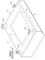
- a seal-shaped light emitting body 47A2 is attached to the four corners of the surface 46 of the photographing table 23.
- the light emitting body 47 can be provided more easily. Further, when the light emitting body 47 deteriorates in timekeeping, it can be easily replaced with a new one.
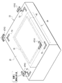
- a recess 70 may be formed on the outer peripheral surface, and the light emitting body 47 may be fitted in the recess 70.
- the recess 70 has a size slightly smaller than that of the light emitter 47, and the light emitter 47 is press-fitted into the recess 70.
- FIG. 12 shows how the block-shaped light emitter 47A3 is fitted into the recesses 70 formed at the four corners of the surface 46 of the photographing table 23, as in the case of FIGS. 5 and 11. In this way, if the concave portion 70 is formed on the outer peripheral surface and the light emitting body 47 is fitted in the concave portion 70, as in the case of the seal of FIG. 11, when the light emitting body 47 deteriorates in timekeeping, it can be easily replaced with a new one. Can be exchanged.
- FIGS. 11 and 12 show an example in which the light emitters 47A2 and 47A3 are used instead of the light emitters 47A1, the light emitters 47B and 47C may also be used as a seal or may be fitted in the recess 70. .. Similarly, the light emitters 47D (see FIGS. 20 and 21), 47E (see FIG. 23), 47F (see FIG. 26), and 47G (see FIG. 27) described below may be used as paints or seals. Alternatively, it may be configured to be fitted in the recess 70.
- an ultraviolet shielding member 75 that shields ultraviolet rays that are sensitive to the light emitting body 47 is provided.
- the light emitting body 47 is covered with the ultraviolet shielding member 75.
- the ultraviolet shielding member 75 is a seal that can be peelably attached to the outer peripheral surface.
- the ultraviolet shielding member 75 transmits visible light, but shields ultraviolet rays that are sensitive to the light emitting body 47.
- the ultraviolet rays that make the illuminant 47 sensitive are not only ultraviolet rays UVX for sterilization, but also, for example, ultraviolet rays contained in the illumination light from a fluorescent lamp installed in the radiation photographing room, or sunlight inserted into the radiation photographing room. It also includes UVN (see FIG. 14) such as UV contained.
- the ultraviolet UVX for sterilization when the ultraviolet UVX for sterilization is not irradiated, the light emitting body 47 is covered with the ultraviolet shielding member 75, whereby the irradiation of the ultraviolet UVN to the light emitting body 47 is prevented.
- the ultraviolet shielding member 75 when the ultraviolet UVX for sterilization is irradiated, the ultraviolet shielding member 75 is peeled off by the operator, and the light emitting body 47 is exposed. As a result, ultraviolet UVX for sterilization is applied to the light emitter 47.
- FIGS. 13 and 14 show an embodiment in which the light emitting body 47A1 provided on the surface 46 of the photographing table 23 is covered with the ultraviolet shielding member 75.
- the ultraviolet shielding member that shields the ultraviolet rays that are sensitive to the light emitting body 47. 75 is provided. Therefore, it is possible to prevent the illuminant 47 from inadvertently emitting light in response to the ultraviolet UVN when the ultraviolet UVX for sterilization is not irradiated. Although the illuminant 47 emits light in response to the ultraviolet UVN, there is no possibility of giving the operator a false recognition that the ultraviolet UVX for sterilization is irradiated or the effect of sterilization is sustained. Further, since the ultraviolet shielding member 75 transmits visible light, even if the light emitting body 47 is covered with the ultraviolet shielding member 75, the operator can visually recognize that the light emitting body 47 is emitting light.
- the ultraviolet shielding member 75 is a seal that can be peelably attached to the outer peripheral surface. Therefore, the ultraviolet shielding member 75 can be attached or peeled off relatively easily.
- a laminated structure 77 in which a light emitting body 47 and an ultraviolet shielding member 75 are both sealed and a plurality of these are alternately laminated may be provided on the outer peripheral surface.
- a new illuminant 47 and an ultraviolet shielding member 75 can always be used for each irradiation of ultraviolet UVX for sterilization.
- the UV shielding member 75 is not limited to the seal. As an example, as shown in FIG. 16, the ultraviolet shielding member 75 may be a shutter.
- the ultraviolet shielding member 75 is a fan-shaped shutter that opens and closes around the drive shaft 80. More specifically, when the ultraviolet UVX for sterilization is not irradiated, the ultraviolet shielding member 75 is in the first position covering the light emitting body 47. This prevents the illuminant 47 from being irradiated with ultraviolet UVN. On the other hand, when the ultraviolet UVX for sterilization is irradiated, the ultraviolet shielding member 75 is in the second position where the light emitting body 47 is exposed. As a result, ultraviolet UVX for sterilization is applied to the light emitter 47. Note that FIG. 16 shows an embodiment in which the light emitting body 47A1 provided on the surface 46 of the photographing table 23 is covered with the ultraviolet shielding member 75, as in the case of FIGS. 13 and 14.
- the control device 12 controls the movement of the ultraviolet shielding member 75 between the first position and the second position. Specifically, when the ultraviolet source 34 does not irradiate the ultraviolet UVX for sterilization, the control device 12 sets the ultraviolet shielding member 75 as the first position. On the other hand, when the ultraviolet UVX for sterilization is irradiated from the ultraviolet source 34 in response to the operation of the lighting instruction switch 41, the control device 12 sets the ultraviolet shielding member 75 as the second position.
- the ultraviolet shielding member 75 is a shutter that moves between the first position that covers the light emitting body 47 and the second position that exposes the light emitting body 47, the ultraviolet shielding member 75 is attached or peeled off. You can save the trouble of doing it.
- the shape of the shutter is not limited to the illustrated fan shape, and may be, for example, a rectangular shape.
- a light emitting body 47 is provided on the outer peripheral surface of the electronic cassette 105 used in the mobile radiation generator 90.
- the mobile radiation generator 90 includes a main body portion 91, a support column portion 92, and an arm portion 93.
- Four wheels 94 are attached to the lower part of the main body 91 on the front, rear, left and right sides.
- the mobile radiation generator 90 can move in the medical facility by the wheel 94, and is used for so-called round-trip radiography in which a patient is photographed while rotating around a hospital room. Therefore, the mobile radiation generator 90 is also called a round-trip car.
- the mobile radiation generator 90 can be brought into the operating room and radiographed during the operation.
- the main body portion 91 includes a central portion 95 and a holder portion 96.
- a control device 97 is built in the central portion 95.
- the holder portion 96 is arranged on the back surface of the central portion 95.
- the holder portion 96 has a holder portion main body 100 and a lid 101.
- the lid 101 can be opened and closed with respect to the holder main body 100 (see FIG. 18).
- the holder portion main body 100 is provided with holders 102A, 102B, and 102C.
- the holders 102A to 102C each detachably accommodate one electronic cassette 105.
- the electronic cassette 105 has a plurality of types such as 17-inch x 17-inch, 17-inch x 14-inch, and 12-inch x 10-inch vertical and horizontal sizes.
- the holders 102A to 102C can accommodate the electronic cassette 105 having a plurality of types, regardless of the type.
- the electronic cassette 105 is an example of a "medical device" according to the technique of the present disclosure. In the following, the holders 102A to 102C may be collectively referred to as the holder 102.
- a handle 107 is provided at a position protruding above the central portion 95.
- the handle 107 has a long columnar shape in the width direction of the central portion 95. The handle 107 is gripped by the operator when maneuvering the mobile radiation generator 90.
- An irradiation switch 108 is attached to the upper part of the back surface of the central portion 95.
- the irradiation switch 108 is a switch for the operator to instruct the start of irradiation of the radiation R.
- An extension cable (not shown) is connected to the irradiation switch 108, and it can be used by removing it from the central portion 95.
- the strut portion 92 is a prismatic shape and is erected along the height direction.
- the strut portion 92 is arranged at the upper portion of the front wheel 94 and at the center position in the width direction.
- the arm portion 93 is prismatic like the strut portion 92.
- the base end of the arm portion 93 is attached to the support column portion 92.
- a radiation source 110 is attached to the arm portion 93 at a tip that is a free end opposite to the base end.
- the radiation source 110 has a built-in radiation tube 111. Further, an irradiation field limiting device 112 is attached to the radiation source 110.
- the strut portion 92 can rotate about the vertical axis with respect to the main body portion 91. Further, the support column portion 92 can be expanded and contracted up and down along the height direction.
- the arm portion 93 is bent at a right angle to the strut portion 92.
- the arm portion 93 can be expanded and contracted back and forth with respect to the support column portion 92 along a direction orthogonal to the height direction.
- the radiation source 110 and the irradiation field limiter 112 can rotate around an axis parallel to the width direction thereof. Further, the radiation source 110 and the irradiation field limiter 112 can rotate about an axis parallel to the front-back direction thereof.
- the holder 102A is provided with an ultraviolet source 120A.
- the ultraviolet source 120A has substantially the same length as the width of the holder 102A.
- the ultraviolet source 120A irradiates the electronic cassette 105 housed in the holder 102A with ultraviolet UVX for sterilization.
- the holder 102B is provided with an ultraviolet source 120B
- the holder 102C is provided with an ultraviolet source 120C.
- a total of nine ultraviolet sources 120B are arranged, four on each of the two side surfaces of the holder 102B facing the front surface 133 and the back surface 134 of the electronic cassette 105, and one on the inner surface of the top plate of the lid 101.
- four ultraviolet sources 120C are arranged on each of the two side surfaces of the holder 102C facing the front surface 133 and the back surface 134 of the electronic cassette 105, and one on the inner surface of the top plate of the lid 101, for a total of nine.
- the ultraviolet source 120B irradiates the electronic cassette 105 housed in the holder 102B with ultraviolet UVX for sterilization.
- the ultraviolet source 120C irradiates the electronic cassette 105 housed in the holder 102C with ultraviolet UVX for sterilization.
- the ultraviolet sources 120A to 120C as with the ultraviolet source 34, an LED (Light Emitting Diode), LD (Laser Diode), or the like may be adopted in addition to a general ultraviolet lamp using a quartz tube such as an excimer lamp. can. Further, the sterilizing ultraviolet UVX irradiated by the ultraviolet sources 120A to 120C has a center wavelength of 200 nm or more and 280 nm or less (for example, 254 nm or 222 nm), and the intensity is constant. In the following, the ultraviolet sources 120A to 120C may be collectively referred to as the ultraviolet source 120.
- the holder 102A is provided with a detachable sensor 121A.
- the attachment / detachment sensor 121A detects whether or not the electronic cassette 105 is housed inside the holder 102A.
- the detachable sensor 121A is a limit switch that turns on when the electronic cassette 105 is housed in the holder 102A and turns off when the electronic cassette 105 is removed from the holder 102A.
- the detachable sensor 121A is a photo sensor composed of a light emitting unit and a light receiving unit.
- the holder 102B is provided with the detachable sensor 121B
- the holder 102C is provided with the detachable sensor 121C.
- the attachment / detachment sensor 121B detects whether or not the electronic cassette 105 is housed inside the holder 102B.
- the detachable sensor 121C detects whether or not the electronic cassette 105 is housed inside the holder 102C.
- the detachable sensors 121A to 121C may be collectively referred to as the detachable sensor 121.
- a lid sensor 122 is provided at the engagement portion of the holder portion main body 100 with the lid 101.
- the lid sensor 122 detects the opening and closing of the lid 101.
- the lid sensor 122 is a limit switch that turns on when the lid 101 is closed and turns off when the lid 101 is opened.
- the lid sensor 122 is a photo sensor composed of a light emitting unit and a light receiving unit. In this case, when the lid 101 is closed, the light from the light projecting unit is blocked, and when the lid 101 is opened, the light from the light projecting unit is received by the light receiving unit.
- the ultraviolet source 120 it is detected by the detachable sensor 121 that the electronic cassette 105 is housed inside the holder 102 (the detachable sensor 121 is turned on), and the lid 101 is opened by the lid sensor 122.
- the lid sensor 122 is turned on
- irradiation with ultraviolet UVX for sterilization is started.
- the ultraviolet source 120 stops the irradiation of the sterilizing ultraviolet UVX.
- the ultraviolet source 120 is a sterilizing ultraviolet UVX when it is detected by the detachable sensor 121 that the electronic cassette 105 is not housed inside the holder 102 (the detachable sensor 121 is turned off). Do not irradiate. In this case, even when the lid 101 is closed and the lid sensor 122 is turned on, the ultraviolet source 120 does not irradiate the ultraviolet UVX for sterilization.
- the ultraviolet source 120 has a sterilizing ultraviolet UVX. Stop the irradiation of. When it is detected again by the lid sensor 122 that the lid 101 is closed, the ultraviolet source 120 resumes irradiation with ultraviolet UVX for sterilization.
- the electronic cassette 105 has a housing 130, a detection panel 131, a battery 132, and the like.
- the housing 130 has a rectangular rectangular parallelepiped shape with a rectangular planar shape, and houses the detection panel 131, the battery 132, and the like inside.
- the battery 132 is detachably loaded in the central portion of the back surface 134 of the housing 130.
- Most of the surface 133 of the housing 130 is made of a material that transmits radiation R such as carbon.
- the portion formed by the material that transmits the radiation R such as carbon is the region IA to which the radiation R is irradiated.
- the electronic cassette 105 is placed under the patient P lying on the bed with the surface 133 of the housing 130 facing the radiation source 110.
- the housing 130 includes a control circuit that controls the operation of the detection panel 131, and a radiation image is generated by converting the signal charge of the pixels of the detection panel 131 into pixel values. It has a built-in signal processing circuit and the like. In addition, a wireless communication unit or the like that performs wireless communication with the control device 97 is also built-in.
- the electronic cassette 105 has a function of detecting the start and end of irradiation of radiation R.
- the control circuit that controls the operation of the detection panel 131 causes the detection panel 131 to perform the storage operation of accumulating the signal charge in the pixels.
- the control circuit causes the detection panel 131 to perform a read operation of reading the accumulated signal charge from the pixel. As a result, a radiation image is output from the detection panel 131.
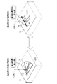
- L-shaped light emitters 47D are provided at the four corners of the surface 133 of the housing 130 along the shape of the corners. Further, as shown in FIG. 21, a rectangular light emitting body 47D is provided on the back surface 134 of the housing 130 so as to sandwich the battery 132.
- the front surface 133 and the back surface 134 of the housing 130 are examples of "at least a part of the outer peripheral surface” according to the technique of the present disclosure.
- the illuminant 47D starts emitting light by irradiating the sterilizing ultraviolet UVX from the ultraviolet source 120, and dims after the irradiation of the sterilizing ultraviolet UVX is stopped. It emits visible light. As a result, the illuminant 47D displays whether or not the ultraviolet source 120 has irradiated the ultraviolet UVX for sterilization, and whether or not the effect of sterilization by the ultraviolet UVX for sterilization from the ultraviolet source 120 is sustained.
- the light emitting body 47D is provided on the front surface 133 and the back surface 134 of the electronic cassette 105 in which the detection panel 131 that detects the radiation R and outputs the radiation image is built in the portable housing 130. ..
- the front surface 133 and the back surface 134 of the electronic cassette 105 are locations contaminated by the patient P or the like. Therefore, by providing the light emitter 47D in the electronic cassette 105, whether or not the ultraviolet UVX for sterilization is applied to the portion contaminated by the patient P or the like, and for sterilization in the portion contaminated by the patient P or the like. It is possible to visually clarify whether or not the bactericidal effect of the ultraviolet UVX is sustained.
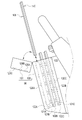
- the holder 102 may be capable of accommodating the electronic cassette 105 with the grid 140 attached.
- the grid 140 is detachably attached to the surface 133 of the housing 130 of the electronic cassette 105.
- the grid 140 removes the scattered radiation generated when the radiation R passes through the patient P.
- the grid 140 is composed of a rectangular plate-shaped grid main body 141 and a holding frame 142 that holds the grid main body 141.
- the grid body 141 has a size that covers substantially the entire surface 133 of the housing 130 when the grid 140 is attached to the surface 133 of the housing 130.
- the area occupied by the grid body 141 corresponds to the area IA to which the radiation R is irradiated.
- the holding frame 142 is made of a conductive material having electromagnetic wave shielding properties such as aluminum or stainless steel, and has a size slightly larger than the surface 133 of the housing 130.
- the holding frame 142 is provided with a mechanism for fixing the grid 140 to the surface 133 of the housing 130 to prevent the grid 140 from falling off.
- a light emitter 47E is provided on the surface 143 of the holding frame 142.
- the surface 143 of the holding frame 142 is outside the region IA to which the radiation R is irradiated. That is, the light emitting body 47E is provided outside the region IA to which the radiation R is irradiated.
- the surface 143 of the holding frame 142 is an example of "at least a part of the outer peripheral surface” according to the technique of the present disclosure.
- the illuminant 47E starts emitting light by irradiating the sterilizing ultraviolet UVX from the ultraviolet source 120, and emits visible light that is dimmed after the irradiation of the sterilizing ultraviolet UVX is stopped. As a result, the illuminant 47E displays whether or not the ultraviolet source 120 has irradiated the ultraviolet UVX for sterilization, and whether or not the effect of sterilization by the ultraviolet UVX for sterilization from the ultraviolet source 120 is sustained.
- the surface of the grid 140 is also a place contaminated by patient P and the like. Therefore, by providing the light emitter 47E on the grid 140, whether or not the ultraviolet UVX for sterilization is applied to the portion contaminated by the patient P or the like, and whether or not the portion contaminated by the patient P or the like is sterilized. It is possible to visually clarify whether or not the bactericidal effect of ultraviolet UVX is sustained.
- the ultraviolet shielding member 75 that shields the ultraviolet rays that sensitize the illuminant of the second embodiment may be applied to the illuminants 47D and 47E.
- a mechanism for peeling off the ultraviolet shielding member 75 when the electronic cassette 105 or the electronic cassette 105 with the grid 140 attached is housed in the holder 102, a mechanism for peeling off the ultraviolet shielding member 75 (when the ultraviolet shielding member 75 is a seal).
- a mechanism for moving the ultraviolet shielding member 75 to the second position is provided so that the light emitters 47D and 47E are automatically exposed in the holder 102. It is also good.
- the lid 101 may not be present, but it is preferable to have the lid 101 from the viewpoint of preventing humans from being irradiated with ultraviolet UVX for sterilization.
- the location of the ultraviolet source 120 that irradiates the electronic cassette 105 and / or the grid 140 with ultraviolet UVX for sterilization is not limited to the holder 102 of the exemplary mobile radiation generator 90.
- An ultraviolet source 120 may be provided in a holder of a charging cradle in which the electronic cassette 105 is detachably housed to charge the battery 132 of the electronic cassette 105.
- the technique of the present disclosure is applied to the radiation diagnostic apparatus 150 shown in FIGS. 24 and 25 as an example.
- the radiation diagnostic device 150 includes a radiation source 151, a control device 152, a standing position photographing table 153, and a lying position photographing table 154.
- the radiation source 151 is also used in the standing position photographing table 153 and the lying position photographing table 154.
- the standing position photographing table 153 and the lying position photographing table 154 are examples of "medical equipment" according to the technique of the present disclosure.
- the radiation source 151 has a built-in radiation tube 155. Further, an irradiation field limiting device 156 is attached to the radiation source 151. Three ultraviolet sources 157A, 157B, and 157C are provided on the outer surface of the irradiation field limiting device 156.
- the radiation source 151 is suspended from the ceiling of the radiography room by a support column 158.
- the stanchion 158 is attached to a rail running around the ceiling via wheels.
- the stanchions 158 and thus the radiation source 151 are horizontally movable in the radiography chamber by rails and wheels.
- the support column 158 can be expanded and contracted in the height direction, whereby the radiation source 151 can be moved in the height direction.
- the radiation source 151 is rotatable with respect to the support column 158 with an axis orthogonal to the paper surface as a rotation axis.
- the standing shooting table 153 has a stand 160, a connection portion 161 and a standing holder 162 and the like.
- the stand 160 is composed of a pedestal 163 installed on the floor of the radiography room and a support column 164 extending in the height direction from the pedestal 163.
- the connection portion 161 connects the standing holder 162 to the stand 160.
- the connection portion 161 and the standing holder 162 can be moved in the height direction with respect to the support column 164, and the height can be adjusted according to the height of the patient P or the imaging site.
- the standing holder 162 has a box shape and houses the electronic cassette 165 inside.
- the standing holder 162 is mostly made of a conductive material having electromagnetic wave shielding properties such as aluminum and stainless steel. Further, the standing holder 162 is formed of a material such as carbon that allows most of the surface 182 (see FIG. 26) facing the radiation source 151 to transmit radiation R.
- the electronic cassette 165 is an example of the "radiography cassette" according to the technique of the present disclosure.
- the recumbent position imaging table 154 has a pedestal 170 installed on the floor of the radiography room, a connection portion 171 and a top plate 172, a recumbent position holder 173, and the like.
- the connecting portion 171 connects the top plate 172 to the pedestal 170.
- the pedestal 170 is an elevating type, whereby the height of the top plate 172 and the recumbent holder 173 can be adjusted.
- the top plate 172 has a rectangular plate shape having a length and a width that allows the patient P to lie on his / her back, and is formed of a material that transmits radiation R such as carbon.
- the lying position holder 173 is arranged in the space between the pedestal 170 formed by the connecting portion 171 and the top plate 172.
- the recumbent position holder 173 has a box shape whose upper part is covered with a top plate 172, and houses the electronic cassette 165 inside.
- the recumbent position holder 173 is made of a conductive material having electromagnetic wave shielding properties such as aluminum and stainless steel.
- the recumbent position holder 173 can be slid and moved in the direction along the long side direction of the top plate 172 by a slide mechanism (not shown).
- FIG. 24 shows a case where the electronic cassette 165 is housed in the standing holder 162 of the standing shooting table 153 and radiography is performed using the standing shooting table 153.
- the ultraviolet source 157A irradiates the surface 182 of the standing holder 162 facing the patient P for sterilization ultraviolet UVX.
- the ultraviolet source 157B irradiates the top plate 172 of the recumbent position photographing table 154 with ultraviolet UVX for sterilization.
- the ultraviolet source 157C does not irradiate the sterilizing ultraviolet UVX.
- FIG. 25 shows a case where the electronic cassette 165 is housed in the lying position holder 173 of the lying position photographing table 154 and radiography is performed using the lying position photographing table 154.
- the ultraviolet source 157A irradiates the top plate 172 of the recumbent position photographing table 154 with ultraviolet UVX for sterilization.
- the ultraviolet source 157C irradiates the surface 182 of the standing holder 162 facing the patient P for sterilization ultraviolet UVX.
- the ultraviolet source 157B does not irradiate the sterilizing ultraviolet UVX.
- the control device 152 starts irradiation of ultraviolet UVX for sterilization by the ultraviolet sources 157A to 157C in response to the operator's lighting instruction. Further, the control device 152 stops the irradiation of the sterilizing ultraviolet UVX when the elapsed time from the start of the irradiation of the sterilizing ultraviolet UVX reaches the set time TS.
- a standing tray 180 is set in the standing holder 162 so that it can be inserted and pulled out.
- a rail for guiding the standing tray 180, a standing lock mechanism for locking the standing tray 180 in the inserted state, and the like are provided inside the standing holder 162.
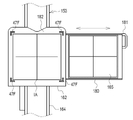
- FIG. 26 shows a state in which the standing lock mechanism is unlocked and the standing tray 180 is pulled out from the standing holder 162.
- An electronic cassette 165 is detachably set on the standing tray 180.
- the standing tray 180 is provided with a holding mechanism for sandwiching and holding the electronic cassette 165 in the vertical direction.
- a handle 181 is provided on the side surface of the standing tray 180.
- the handle 181 is gripped by the operator when the standing tray 180 is inserted into the standing holder 162 and when it is pulled out from the standing holder 162.
- the standing tray 180 is unlocked by the standing lock mechanism.
- the surface 182 of the standing holder 162 has a portion formed of a material that transmits radiation R such as carbon. This portion is the region IA to which the radiation R is irradiated. Outside the region IA to which the radiation R is irradiated, L-shaped light emitters 47F are provided at the four corners of the surface 182 along the shape of the corners.
- the surface 182 is an example of "at least a portion of the outer peripheral surface" according to the technique of the present disclosure.
- the illuminant 47F starts emitting light by irradiating the sterilizing ultraviolet UVX from the ultraviolet source 157A or 157C, and emits visible light that is dimmed after the irradiation of the sterilizing ultraviolet UVX is stopped. Thereby, the illuminant 47F displays whether or not the sterilizing ultraviolet UVX is irradiated from the ultraviolet source 157A or 157C, and whether or not the sterilizing effect of the sterilizing ultraviolet UVX from the ultraviolet source 157A or 157C is sustained. ..
- the recumbent tray 185 is set in the recumbent holder 173 so that it can be inserted and pulled out.
- a rail for guiding the recumbent tray 185 Inside the recumbent holder 173, a rail for guiding the recumbent tray 185, a recumbent lock mechanism for locking the recumbent tray 185 in the inserted state, and the like are provided.
- FIG. 27 shows a state in which the recumbent lock mechanism is unlocked and the recumbent tray 185 is pulled out from the recumbent holder 173.
- the electronic cassette 165 is detachably set on the lying position tray 185.
- the recumbent tray 185 is provided with a holding mechanism for sandwiching and holding the electronic cassette 165 in the left-right direction.
- a handle 186 is provided on the side surface of the recumbent tray 185.
- the handle 186 is gripped by the operator when the recumbent tray 185 is inserted into the recumbent holder 173 and when it is pulled out from the recumbent holder 173.
- the handle 186 is gripped in the inserted state, the recumbent tray 185 is unlocked by the recumbent lock mechanism.
- the radiation R is applied to the region IA corresponding to the moving range of the electronic cassette 165 housed in the recumbent holder 173.
- L-shaped light emitters 47G are provided along the shape of the corners.
- the illuminant 47G is provided outside the region IA.
- the surface 187 is an example of "at least a part of the outer peripheral surface” according to the technique of the present disclosure.
- the illuminant 47G starts emitting light by irradiating the sterilizing ultraviolet UVX from the ultraviolet source 157A or 157B, and emits visible light that is dimmed after the irradiation of the sterilizing ultraviolet UVX is stopped. Thereby, the illuminant 47G displays whether or not the sterilizing ultraviolet UVX is irradiated from the ultraviolet source 157A or 157B, and whether or not the sterilizing effect of the sterilizing ultraviolet UVX from the ultraviolet source 157A or 157B is sustained. ..
- the ultraviolet sources 157A to 157C are provided at locations where the standing position photographing table 153 and the lying position photographing table 154 can be irradiated with the ultraviolet UVX for sterilization. Therefore, the standing position photographing table 153 and the lying position photographing table 154 contaminated by the contact of the patient P can be sterilized. Further, by providing the luminous bodies 47F and 47G on the standing image pickup table 153 and the recumbent image pickup table 154, whether or not the portion contaminated by the patient P or the like was irradiated with the ultraviolet UVX for sterilization, and the patient P. It is possible to visually clarify whether or not the effect of sterilization by ultraviolet UVX for sterilization is sustained in a place contaminated by such as.
- An ultraviolet shielding member 75 that shields ultraviolet rays that sensitize the illuminant of the second embodiment may be applied to the illuminants 47F and 47G.
- the electronic cassette 165 is not detachably accommodated, and the detection panel is detachably accommodated like the imaging table 23 of the mammography apparatus 10. It may be a thing.
- a CR (Computed Radiography) cassette may be used as the radiographing cassette.
- An ultraviolet source is provided inside the standing holder 162 and / or the lying holder 173, and the ultraviolet UVX for sterilizing the radiographic cassette housed in the standing holder 162 and / or the lying holder 173. May be irradiated.
- a light emitter 47 may be provided over the entire outer peripheral surface irradiated with ultraviolet UVX for sterilization. However, this naturally costs money. In addition, the patient P may feel uncomfortable when he / she sees the light emitted as a whole. Further, the light emission may be annoying and may hinder the positioning of the patient P or the like. Therefore, it is preferable to provide the light emitting body 47 on a part of the outer peripheral surface to which the ultraviolet UVX for sterilization is irradiated.
- a selective ultraviolet shielding member may be provided to transmit ultraviolet UVX for sterilization, but to shield ultraviolet UVN such as ultraviolet contained in the illumination light from a fluorescent lamp. In this case, it is not necessary to provide the selective ultraviolet shielding member on the light emitting body 47 so as to be peelable, or to use the selective ultraviolet shielding member as a shutter.
- the light emitter 47 may be coated with a selective ultraviolet shielding member.
- a table showing the relationship between the degree of dimming of the light emitting body 47 and the degree of residual bactericidal effect may be attached in the vicinity of the light emitting body 47 in the form of a seal or the like. In this way, the operator can know the degree of residual bactericidal effect from the degree of dimming.
- medical devices related to radiography such as a mammography apparatus 10, an electronic cassette 105, a standing position imaging table 153, and a lying position imaging table 154 are exemplified, but the technique of the present disclosure is not limited to this. It can be applied to all medical devices that are used repeatedly, such as the sleeper of MRI (Magnetic Response Imaging) equipment, the sleeper of PET (Positron Emission Tomography) equipment, the ultrasonic probe of ultrasonic diagnostic equipment, and the scope of endoscopic equipment. ..
- MRI Magnetic Response Imaging
- PET Pulsitron Emission Tomography
- a and / or B is synonymous with "at least one of A and B". That is, “A and / or B” means that it may be A alone, B alone, or a combination of A and B. Further, in the present specification, when three or more matters are connected and expressed by "and / or", the same concept as “A and / or B" is applied.
Landscapes
- Health & Medical Sciences (AREA)
- Life Sciences & Earth Sciences (AREA)
- Engineering & Computer Science (AREA)
- Medical Informatics (AREA)
- Animal Behavior & Ethology (AREA)
- General Health & Medical Sciences (AREA)
- Public Health (AREA)
- Veterinary Medicine (AREA)
- High Energy & Nuclear Physics (AREA)
- Biophysics (AREA)
- Physics & Mathematics (AREA)
- Epidemiology (AREA)
- Nuclear Medicine, Radiotherapy & Molecular Imaging (AREA)
- Optics & Photonics (AREA)
- Pathology (AREA)
- Radiology & Medical Imaging (AREA)
- Biomedical Technology (AREA)
- Heart & Thoracic Surgery (AREA)
- Molecular Biology (AREA)
- Surgery (AREA)
- Apparatus For Disinfection Or Sterilisation (AREA)
Abstract
外周面と、外周面の少なくとも一部に設けられ、殺菌用の紫外線の照射により発光を開始し、殺菌用の紫外線の照射停止後に減光することで、殺菌用の紫外線が照射されたかどうか、および殺菌用の紫外線による殺菌の効果が持続しているかどうかを表示する可視光を発する発光体と、を備える医療機器。
Description
本開示の技術は、医療機器に関する。
繰り返し使用される医療機器は、患者あるいはオペレータといった人との接触によって細菌および/またはウイルスが付着することで、少なからず汚染される。そこで、従来、例えば特開2013-248124号公報のように、繰り返し使用される医療機器に紫外線を照射することにより殺菌を行う技術が提案されている。なお、殺菌とは、細菌および/またはウイルスを不活性化することを意味する。
特開2013-248124号公報には、繰り返し使用される医療機器として、放射線撮影に使用される電子カセッテが記載されている。特開2013-248124号公報では、病室を回りながら放射線撮影(いわゆる回診撮影)を行う移動式放射線発生装置に備えられた、電子カセッテを収容するホルダの内部に紫外線源を設け、ホルダに収容された電子カセッテに対して紫外線を照射している。
特開2013-248124号公報のように医療機器を紫外線で殺菌すれば、確かに細菌および/またはウイルスへの感染のリスクは低減される。しかしながら、紫外線が照射されたかどうか、および紫外線による殺菌の効果が持続しているかどうかが視覚的に判然としなかった。
本開示の技術に係る1つの実施形態は、殺菌用の紫外線が照射されたかどうか、および殺菌用の紫外線による殺菌の効果が持続しているかどうかを視覚的に判然とさせることが可能な医療機器を提供する。
本開示の医療機器は、外周面と、外周面の少なくとも一部に設けられ、殺菌用の紫外線の照射により発光を開始し、殺菌用の紫外線の照射停止後に減光することで、殺菌用の紫外線が照射されたかどうか、および殺菌用の紫外線による殺菌の効果が持続しているかどうかを表示する可視光を発する発光体と、を備える。
発光体は、殺菌用の紫外線の照射停止後に減光しながら消光することが好ましい。
殺菌用の紫外線の照射停止後から発光体が消光するまでの時間は、殺菌用の紫外線による殺菌の効果の持続時間よりも短いことが好ましい。
発光体は、外周面に塗布される塗料であることが好ましい。
発光体は、外周面に剥離可能に貼り付けられるシールであることが好ましい。
外周面には凹部が形成されており、発光体は凹部に嵌め込まれることが好ましい。
可視光を透過し、発光体を覆うことが可能で、発光体を覆っている状態においては、発光体を感応させる紫外線を遮蔽する紫外線遮蔽部材を備えることが好ましい。
紫外線遮蔽部材は、外周面に剥離可能に貼り付けられるシールであることが好ましい。
紫外線遮蔽部材は、発光体を覆う第1位置と、発光体を露呈する第2位置との間で移動するシャッタであることが好ましい。
放射線が照射され、発光体は、放射線が照射される領域外に設けられていることが好ましい。
放射線を検出して放射線画像を出力する検出パネルが内蔵され、患者の乳房が載置される撮影台と、撮影台との間で乳房を挟み込んで圧迫する圧迫板とを有する乳房撮影装置であることが好ましい。
放射線を検出して放射線画像を出力する検出パネルが可搬型の筐体に内蔵された電子カセッテであることが好ましい。
放射線撮影用カセッテを収容するホルダを有し、患者を立位姿勢または臥位姿勢で撮影するための立位撮影台または臥位撮影台であることが好ましい。
本開示の技術によれば、殺菌用の紫外線が照射されたかどうか、および殺菌用の紫外線による殺菌の効果が持続しているかどうかを視覚的に判然とさせることが可能な医療機器を提供することができる。
[第1実施形態]
一例として図1および図2に示すように、乳房撮影装置10は、患者Pの乳房Mを被写体とする。乳房撮影装置10は、乳房MにX線、γ線といった放射線Rを照射して、乳房Mの放射線画像を撮影する。乳房撮影装置10は、本開示の技術に係る「医療機器」の一例である。
一例として図1および図2に示すように、乳房撮影装置10は、患者Pの乳房Mを被写体とする。乳房撮影装置10は、乳房MにX線、γ線といった放射線Rを照射して、乳房Mの放射線画像を撮影する。乳房撮影装置10は、本開示の技術に係る「医療機器」の一例である。
乳房撮影装置10は、装置本体11と制御装置12とを備える。装置本体11は、例えば医療施設の放射線撮影室に設置される。制御装置12は、例えば放射線撮影室の隣室の制御室に設置される。制御装置12は、例えばデスクトップ型のパーソナルコンピュータである。制御装置12は、LAN(Local Area Network)等のネットワーク13を介して、画像データベース(以下、DB(Data Base)と略す)サーバ14と通信可能に接続されている。画像DBサーバ14は、例えば、PACS(Picture Archiving and Communication System)サーバであり、乳房撮影装置10から放射線画像を受信し、受信した放射線画像を蓄積管理する。
ネットワーク13には、端末装置15も接続されている。端末装置15は、例えば、放射線画像を用いて診察を行う医師が使用するパーソナルコンピュータである。端末装置15は、画像DBサーバ14から放射線画像を受信し、受信した放射線画像をディスプレイに表示する。
装置本体11は、スタンド20とアーム21とを有する。スタンド20は、放射線撮影室の床面に設置される台座20Aと、台座20Aから高さ方向に延びる支柱20Bとで構成される。アーム21は横から見た形状が略C字状であり、接続部21Aを介して支柱20Bに接続されている。この接続部21Aにより、アーム21は支柱20Bに対して高さ方向に移動可能で、患者Pの身長に応じた高さ調節が可能となっている。また、アーム21は、接続部21Aを貫く、支柱20Bに垂直な回転軸回りに回転可能である。
アーム21は、線源収容部22、撮影台23、および本体部24で構成される。線源収容部22には放射線源25が収容されている。撮影台23には乳房Mが載せられる。撮影台23には検出パネル26が収容されている。本体部24は、線源収容部22と撮影台23とを一体的に接続する。本体部24は、線源収容部22と撮影台23とを対向する位置に保持する。本体部24の両サイドには、患者Pの手が掴まれる手すり27が設けられている。
本体部24には、間接照明ランプ28が取り付けられている。間接照明ランプ28は、患者Pの不安を和らげるために、暖色系の仄暗い間接照明光を支柱20Bに向けて照射する。なお、間接照明ランプ28は、支柱20Bの外面および/または内部に取り付けられていてもよい。この場合、間接照明ランプ28は、間接照明光を本体部24に向けて照射する。
放射線源25は、放射線管29と、放射線管29を収容するハウジング30とで構成される。ハウジング30内は絶縁油で満たされている。放射線管29は、撮影台23に載せられた乳房Mに向けて放射線Rを照射する。検出パネル26は、乳房Mを透過した放射線Rを検出して放射線画像を出力する。
放射線管29は、陰極と陽極とを有している。陰極は電子を放出する。陽極は、電子が衝突することで放射線Rを発する。陰極と陽極とは、略円筒形状の真空のガラス管に収容されている。陰極は例えば冷陰極である。より詳しくは、陰極は、電界放出現象を利用して、陽極に向けて電子線を放出する電子放出源を有する電界放出型である。陽極は、回転機構により回転する回転陽極である。なお、回転せずに位置が固定された固定陽極を用いてもよい。
陰極と陽極との間には、管電圧発生器(図示省略)からの管電圧が印加される。管電圧の印加により、陰極から陽極に向けて電子線が放出される。そして、電子線が衝突した陽極の点(焦点)から、放射線Rが発せられる。放射線Rは、ガラス管に設けられた照射窓から外部に照射される。
線源収容部22と撮影台23との間には、照射野限定器31が設けられている。照射野限定器31はコリメータとも呼ばれ、撮影台23への放射線Rの照射野を規定する。
照射野限定器31には、放射線管29からの放射線Rが入射する入射開口と、放射線Rが出射する出射開口とが形成されている。出射開口の近傍には、4枚の遮蔽板が設けられている。遮蔽板は、放射線Rを遮蔽する材料、例えば鉛等で形成されている。遮蔽板は、四角形の各辺上に配置、換言すれば井桁状(checkered pattern)に組まれており、放射線Rを透過させる四角形の照射開口を形成する。照射野限定器31は、各遮蔽板の位置を変更することで照射開口の大きさを変化させ、これにより撮影台23への放射線Rの照射野を変更する。
照射野限定器31内には、照射野ランプが設けられている。照射野ランプは、例えば橙色の可視光を発する。照射野ランプから発せられた可視光は、照射野を表す光として、出射開口を通じて撮影台23に向けて照射される。なお、放射線Rの線質を変更するためのフィルタを照射野限定器31内に設けてもよい。
線源収容部22には、フェイスガード32が取り付けられている。フェイスガード32は、放射線Rを透過しない材料で形成またはコーティングされており、患者Pの顔を放射線Rから防護する。
撮影台23と照射野限定器31との間には、圧迫板33が取り付けられている。圧迫板33は、放射線Rを透過する材料で形成されている。圧迫板33は、撮影台23と対向する位置に配置されている。圧迫板33は、図示省略した昇降スイッチの操作に応じて、撮影台23に向かう方向と撮影台23から離間する方向とに移動可能である。圧迫板33は、撮影台23に向かって移動して、撮影台23との間で乳房Mを挟み込んで圧迫する。
照射野限定器31の圧迫板33と対向する外面には、紫外線源34が設けられている。より詳しくは、紫外線源34は、フェイスガード32の裏側の照射野限定器31の外面に設けられている。一例として図3に示すように、紫外線源34は、中心波長200nm以上280nm以下(例えば254nm、あるいは222nm)で、かつ一定の強度の殺菌用の紫外線UVXを、フェイスガード32および圧迫板33等に向けて照射する。紫外線源34としては、エキシマランプ等の石英管を用いた一般的な紫外線ランプの他、LED(Light Emitting Diode)、またはLD(Laser Diode)等を採用することができる。
フェイスガード32および圧迫板33は、殺菌用の紫外線UVXを透過する材料で形成されている。殺菌用の紫外線UVXを透過する材料としては、例えばAGC株式会社製の製品名「サイトップ(登録商標)」が挙げられる。このため、殺菌用の紫外線UVXは、フェイスガード32の裏面51(図6参照)からフェイスガード32内に入射し、患者Pの顔と対面するフェイスガード32の表面50(図6参照)を照射する。また、殺菌用の紫外線UVXは、圧迫板33の裏面58(図7参照)から圧迫板33内に入射し、乳房Mが接する圧迫板33の表面57(図7参照)を照射する。さらに、圧迫板33を透過した殺菌用の紫外線UVXは、乳房Mが載せられる撮影台23の表面46(図5参照)を照射する。すなわち、本例においては、主として撮影台23、フェイスガード32、および圧迫板33に殺菌用の紫外線UVXが照射される。
一例として図4に示すように、紫外線源34には、紫外線源制御部40が接続されている。紫外線源制御部40は、紫外線源34の動作を制御する。紫外線源制御部40は、例えばプログラムを実行することにより制御装置12のCPU(Central Processing Unit)に構築される。紫外線源制御部40には、点灯指示スイッチ41が接続されている。点灯指示スイッチ41は、例えば制御装置12のディスプレイにGUI(Graphical User Interface)として表示される。
放射線技師等のオペレータにより、制御装置12の入力デバイスを通じて点灯指示スイッチ41が操作された場合、紫外線源制御部40は、点灯指示信号LISを紫外線源34に出力する。これにより紫外線源34による殺菌用の紫外線UVXの照射が開始される。
紫外線源制御部40は、殺菌用の紫外線UVXの照射開始からの経過時間を計時する。経過時間が予め設定された設定時間TSに達した場合、紫外線源制御部40は、消灯指示信号OISを出力する。これにより紫外線源34による殺菌用の紫外線UVXの照射が停止される。つまり、点灯指示スイッチ41が操作された場合、設定時間TSの間、紫外線源34から殺菌用の紫外線UVXが照射される。
設定時間TSは、細菌および/またはウイルスの殺菌に必要な紫外線UVXの照射時間である。設定時間TSは、殺菌用の紫外線UVXの強度、並びに殺菌対象の細菌および/またはウイルスの種類等により異なるが、大体数秒~数十分である。例えば新型コロナウイルス(SARS(Severe Acute Respiratory Syndrome)-CoV(Coronavirus)-2)は、数秒の紫外線UVXの照射で不活性化するとの報告がある。より詳しくは、中心波長222nm、強度1W/m2の紫外線の場合、30秒間の照射で99.7%が不活性化するとの報告がある(https://xtech.nikkei.com/atcl/nxt/news/18/08672/)。また、中心波長254nmの紫外線の場合、10秒~15秒で99.9%が不活性化するとの報告もある(https://robotstart.info/2020/09/10/uvbuster-covid19.html)。
撮影台23の部分を示す図5において、検出パネル26は矩形状の検出面45を有する。検出面45は、乳房Mを透過した放射線Rを検出する面である。より詳しくは、検出面45は、放射線Rを電気信号に変換する画素が二次元配列された二次元平面である。このような検出パネル26は、FPD(Flat Panel Detector)と呼ばれる。検出パネル26は、放射線Rを可視光に変換するシンチレータを有し、シンチレータが発する可視光を電気信号に変換する間接変換型でもよいし、放射線Rを直接電気信号に変換する直接変換型でもよい。
撮影台23の表面46は、検出パネル26の検出面45よりも一回り大きい矩形状をしている。表面46には、検出面45に対応する領域IA内に放射線Rが照射される。表面46の四隅には、角の形状に沿ってL字状の発光体47A1が設けられている。発光体47A1は、領域IA外に設けられている。発光体47A1は、スクリーン印刷等により表面46に塗布される塗料である。表面46は、本開示の技術に係る「外周面の少なくとも一部」の一例である。
一例として図6に示すように、フェイスガード32の表面50の上部には、矩形状の発光体47Bが設けられている。発光体47Bは、発光体47A1と同様に、スクリーン印刷等により表面50に塗布される塗料である。表面50は、本開示の技術に係る「外周面の少なくとも一部」の一例である。
一例として図7に示すように、圧迫板33は、箱状の圧迫板本体55と、圧迫板本体55を本体部24に昇降可能に取り付ける取付部56とを有する。圧迫板本体55の裏面58には、領域IA内に放射線Rが照射される。領域IAは、裏面58よりも一回り小さい。
圧迫板本体55の開口縁面59、および取付部56の基部60の表面61には、発光体47Cが設けられている。発光体47Cは、発光体47A1および47Bと同様に、スクリーン印刷等により開口縁面59および表面61に塗布される塗料である。開口縁面59および表面61は、領域IA外である。つまり、発光体47Cは、領域IA外に設けられている。開口縁面59および表面61は、本開示の技術に係る「外周面の少なくとも一部」の一例である。なお、以下の説明では、発光体47A1~47Cを、まとめて発光体47と表記する場合がある。
一例として図8に示すように、発光体47は、殺菌用の紫外線UVXの照射により可視光の発光を開始する。発光体47は、殺菌用の紫外線UVXの照射直後に可視光の発光量が最大値(MAX)に達する。発光体47は、殺菌用の紫外線UVXが設定時間TS照射されている間、最大の発光量を維持する。発光体47は、殺菌用の紫外線UVXの照射停止後に発光量が徐々に減少(減光)する。そして、発光体47は、殺菌用の紫外線UVXの照射停止から時間TAの経過後に消光する。この可視光の発光により、発光体47は、殺菌用の紫外線UVXが照射されたかどうか、および殺菌用の紫外線UVXによる殺菌の効果が持続しているかどうかを表示する。
殺菌用の紫外線UVXによる殺菌の効果は、殺菌用の紫外線UVXの照射開始から徐々に増加し、照射開始からの経過時間が設定時間TSに達して殺菌用の紫外線UVXの照射が停止された場合に最大値(MAX)に達する。殺菌の効果は、殺菌用の紫外線UVXの照射停止直後は最大値を維持しているが、徐々に減少する。そして、殺菌用の紫外線UVXの照射停止から時間TBの経過後に消失する。なお、殺菌の効果が最大値(MAX)に達するとは、例えば、殺菌用の紫外線UVXが照射された領域における細菌および/またはウイルスの不活性化率が99%以上、好ましくは99.9%以上になった場合を指す。なお、最大値(MAX)の値は、殺菌用の紫外線UVXの波長、強度等の照射条件、細菌および/またはウイルスの種類、温湿度等の環境条件、不活性化率の測定方法等によって異なる場合がある。
殺菌用の紫外線UVXの照射停止後から発光体47が消光するまでの時間(以下、発光体47の消光時間という)TAは、殺菌用の紫外線UVXによる殺菌の効果の持続時間TBよりも短い。殺菌の効果の持続時間TBは、殺菌用の紫外線UVXの強度、並びに殺菌対象の細菌および/またはウイルスの種類等により異なるが、大体数分~数時間である。発光体47の消光時間TAは、例えば殺菌の効果の持続時間TBの7割~8割である。殺菌の効果の持続時間TBが例えば10分であった場合、発光体47の消光時間TAは例えば7分~8分である。なお、発光体47としては、株式会社アサヒペン製の夜光塗料(https://www.asahipen.jp/products/view/16813)、立山科学工業株式会社製の透明性蓄光塗料(https://www.tateyama.jp/product/dev_newmaterial.html)等を採用することができる。
次に、上記構成による作用について、図9に示すフローチャートを参照して説明する。オペレータは、撮影台23、フェイスガード32、および圧迫板33等、患者Pによって汚染された箇所を殺菌する目的で、点灯指示スイッチ41を操作して殺菌用の紫外線UVXの点灯を指示する(ステップST100でYES)。これにより紫外線源制御部40から紫外線源34に点灯指示信号LISが出力され、紫外線源34から殺菌用の紫外線UVXが照射される(ステップST110)。また、殺菌用の紫外線UVXが照射された発光体47から可視光が発光される(ステップST120)。
殺菌用の紫外線UVXの照射開始からの経過時間が設定時間TSに達した場合(ステップST130でYES)、紫外線源制御部40から紫外線源34に消灯指示信号OISが出力される。これにより殺菌用の紫外線UVXの照射が停止される(ステップST140)。そして、発光体47が減光しながら消光する(ステップST150)。
殺菌用の紫外線UVXの照射後、オペレータは、患者Pを放射線撮影室に入室させる。そして、患者Pの乳房Mを撮影台23に載せて圧迫板33で圧迫する。オペレータは、制御室に移動して、制御装置12を介して放射線Rの照射条件を設定した後、放射線撮影の開始指示を入力する。これにより照射条件にしたがって放射線管29が動作され、放射線Rが照射される。放射線管29から照射された放射線Rは、照射野限定器31に入射される。照射野限定器31に入射された放射線Rは、遮蔽板により形成された照射開口を通過する。これにより放射線Rの照射野が規定される。
照射野限定器31により照射野が規定されて乳房Mに照射された放射線Rは、検出パネル26により検出される。これにより検出パネル26から放射線画像が出力される。放射線画像は、制御装置12において各種画像処理が施された後、制御装置12のディスプレイに表示される。
以上説明したように、乳房撮影装置10は、撮影台23の表面46、フェイスガード32の表面50、圧迫板本体55の開口縁面59、および取付部56の基部60の表面61に設けられた発光体47を備える。発光体47は、殺菌用の紫外線UVXの照射により発光を開始し、殺菌用の紫外線UVXの照射停止後に減光することで、殺菌用の紫外線UVXが照射されたかどうか、および殺菌用の紫外線UVXによる殺菌の効果が持続しているかどうかを表示する。したがって、殺菌用の紫外線UVXが照射されたかどうか、および殺菌用の紫外線UVXによる殺菌の効果が持続しているかどうかを視覚的に判然とさせることが可能となる。
発光体47の減光の程度が大きく、殺菌の効果が薄らいでいると判断した場合に、再度殺菌用の紫外線UVXを照射して殺菌の効果を復活させるといった対策を講じることができる。このため、細菌および/またはウイルスへの感染のリスクをさらに低減することができる。
図8で示したように、発光体47は、殺菌用の紫外線UVXの照射停止後に減光しながら消光する。このため、発光量の多寡に関わらず、とにかく発光体47から可視光が発せられている場合は、少なくとも殺菌用の紫外線UVXが照射されたことを明確に表示することができる。
また、図8で示したように、発光体47の消光時間TAは、殺菌用の紫外線UVXによる殺菌の効果の持続時間TBよりも短い。
逆に発光体47の消光時間TAが殺菌の効果の持続時間TBよりも長い場合は、殺菌の効果が消失しているにも関わらず発光体47が可視光を発している場合があり得る。この場合は、殺菌の効果が持続しているという誤った認識をオペレータに与えるおそれがある。本開示の技術では、前述のように発光体47の消光時間TAが殺菌の効果の持続時間TBよりも短いので、そうした懸念はない。
図5~図7で示したように、発光体47は、撮影台23の表面46、フェイスガード32の表面50、圧迫板本体55の開口縁面59、および取付部56の基部60の表面61に塗布される塗料である。このため、比較的容易に発光体47を設けることができる。
図5および図7で示したように、発光体47は、放射線Rが照射される領域IA外に設けられている。このため、発光体47が放射線画像に写り込む等、発光体47による放射線画像の画質劣化を防止することができる。
乳房撮影装置10は、放射線Rを検出して放射線画像を出力する検出パネル26が内蔵され、患者Pの乳房Mが載置される撮影台23と、撮影台23との間で乳房Mを挟み込んで圧迫する圧迫板33とを有する。撮影台23および圧迫板33には、殺菌用の紫外線UVXが照射される。また、撮影台23および圧迫板33には、発光体47が設けられる。撮影台23および圧迫板33は、患者P等によって汚染される箇所である。したがって、撮影台23および圧迫板33に発光体47を設けることで、患者P等によって汚染される箇所に対して、殺菌用の紫外線UVXが照射されたかどうか、および患者P等によって汚染される箇所における、殺菌用の紫外線UVXによる殺菌の効果が持続しているかどうかを視覚的に判然とさせることができる。
殺菌用の紫外線UVXの照射開始からの経過時間が設定時間TSに達した場合に、殺菌用の紫外線UVXの照射を停止しているが、これに限らない。点灯指示スイッチ41と対で消灯指示スイッチを設け、消灯指示スイッチを通じてオペレータによる消灯の指示があった場合に、殺菌用の紫外線UVXの照射を停止してもよい。
カメラの撮影画像、あるいは人感センサ等によって、患者P等の人が放射線撮影室を退室したことを検知した場合に、紫外線源制御部40により紫外線源34の動作を制御して、殺菌用の紫外線UVXの照射を開始させてもよい。この場合、殺菌用の紫外線UVXの照射中に人が放射線撮影室に入室したことを検知したら、殺菌用の紫外線UVXの照射を停止させて、人に殺菌用の紫外線UVXが照射されることを防止してもよい。
紫外線源34を設ける箇所は、例示の照射野限定器31の外面に限らない。照射野限定器31の内部に紫外線源34を設けてもよい。より詳しくは、照射野ランプと並んで紫外線源34を設ける。紫外線源34から発せられた殺菌用の紫外線UVXは、照射野ランプから発せられた可視光と同様に、照射野限定器31の出射開口を通じて撮影台23に向けて照射される。この際、遮蔽板は、殺菌用の紫外線UVXの照射範囲が最大となるよう、照射開口の大きさが最大となる位置に移動される。
このように、照射野限定器31の内部に紫外線源34を設ければ、患者Pおよびオペレータに触れられることがないので、ぶつかって破損するおそれがない。また、照射野ランプと並んで紫外線源34を設ければ、照射野ランプからの可視光と同じ機構を利用して殺菌用の紫外線UVXを照射することができる。ただし、照射開口の大きさが最大となる位置に遮蔽板を移動させる必要があるので、そうした制御をする必要がないという点では、照射野限定器31の外面に紫外線源34を設けるほうが好ましい。
紫外線源34の設置箇所は、照射野限定器31の外面または内部に限らず、紫外線源34の設置個数も1個に限らない。一例として図10に示すように、照射野限定器31の本体部24と対向する外面、および間接照明ランプ28の隣り等、あらゆる箇所に紫外線源34を設けてもよい。患者P等によって汚染される箇所に殺菌用の紫外線UVXを照射可能な箇所であれば、どこでも構わない。スタンド20、本体部24、および手すり27等、照射野限定器31に設けられた1個の紫外線源34ではカバーしきれない箇所を殺菌することができる。紫外線源34に首振り機能をもたせ、1台で広範な箇所をカバーする構成としてもよい。
さらに、磁石等で取り外し可能で、かつ制御装置12と無線通信を行う紫外線源34を用いてもよい。こうした紫外線源34によれば、殺菌したい箇所に自由に取り付けることができる。あるいは、放射線撮影室の壁面または天井等、装置本体11とは離れた箇所に、ネジ等の簡易な取付具によって紫外線源34を取り付けてもよい。この場合、制御装置12との通信は無線で行うことが好ましい。
発光体47の設置箇所も同様に、例示の撮影台23の表面46、フェイスガード32の表面50、圧迫板本体55の開口縁面59、および取付部56の基部60の表面61に限らない。スタンド20、本体部24、手すり27等の表面に発光体47を設けてもよい。
発光体47は塗料に限らない。一例として図11に示すように、発光体47は、外周面に剥離可能に貼り付けられるシールであってもよい。図11においては、図5の場合と同様、撮影台23の表面46の四隅に、シール状の発光体47A2が貼り付けられる様子を示している。このように、発光体47を外周面に剥離可能に貼り付けられるシールとすれば、さらに容易に発光体47を設けることができる。また、発光体47が計時劣化した場合に、簡単に新品に交換することができる。
また、一例として図12に示すように、外周面に凹部70を形成し、凹部70に発光体47を嵌め込む構成としてもよい。凹部70は、発光体47よりも僅かに小さいサイズを有し、発光体47は凹部70に圧入される。図12においては、図5および図11の場合と同様、撮影台23の表面46の四隅に形成された凹部70に、ブロック状の発光体47A3が嵌め込まれる様子を示している。このように、外周面に凹部70を形成し、凹部70に発光体47を嵌め込む構成とすれば、図11のシールの場合と同じく、発光体47が計時劣化した場合に、簡単に新品に交換することができる。
図11および図12においては、発光体47A1に代えて発光体47A2および47A3を用いる例を示したが、発光体47Bおよび47Cについても、シールとしてもよいし、凹部70に嵌め込まれる構成としてもよい。以降に説明する発光体47D(図20および図21参照)、47E(図23参照)、47F(図26参照)、および47G(図27参照)も同様に、塗料としてもよいし、シールとしてもよいし、凹部70に嵌め込まれる構成としてもよい。
[第2実施形態]
図13~図16に示す第2実施形態では、発光体47を感応させる紫外線を遮蔽する紫外線遮蔽部材75を設ける。
図13~図16に示す第2実施形態では、発光体47を感応させる紫外線を遮蔽する紫外線遮蔽部材75を設ける。
一例として図13に示すように、発光体47は、紫外線遮蔽部材75で覆われる。紫外線遮蔽部材75は、外周面に剥離可能に貼り付けられるシールである。紫外線遮蔽部材75は、可視光は透過するが、発光体47を感応させる紫外線は遮蔽する。発光体47を感応させる紫外線とは、殺菌用の紫外線UVXはもちろんのこと、例えば、放射線撮影室に設置された蛍光灯からの照明光に含まれる紫外線、あるいは、放射線撮影室に差し込む太陽光に含まれる紫外線といった紫外線UVN(図14参照)も含む。
一例として図14に示すように、殺菌用の紫外線UVXの非照射時、発光体47は紫外線遮蔽部材75で覆われ、これにより発光体47への紫外線UVNの照射が防止される。一方、殺菌用の紫外線UVXの照射時、オペレータにより紫外線遮蔽部材75が剥離され、発光体47は露呈される。これにより殺菌用の紫外線UVXが発光体47に照射される。殺菌用の紫外線UVXの照射が停止された場合、先に剥離された紫外線遮蔽部材75または新しい紫外線遮蔽部材75がオペレータにより発光体47上に再び貼り付けられ、発光体47が紫外線遮蔽部材75で再び覆われる。なお、図13および図14においては、撮影台23の表面46に設けられた発光体47A1を、紫外線遮蔽部材75で覆った態様を示している。
このように、第2実施形態では、可視光を透過し、発光体47を覆うことが可能で、発光体47を覆っている状態においては、発光体47を感応させる紫外線を遮蔽する紫外線遮蔽部材75を備える。このため、殺菌用の紫外線UVXの非照射時に、紫外線UVNに感応して不用意に発光体47が発光することを防止することができる。紫外線UVNに感応して発光体47が発光しているのに、殺菌用の紫外線UVXが照射された、あるいは殺菌の効果が持続しているといった誤った認識をオペレータに与えるおそれがない。また、紫外線遮蔽部材75は可視光を透過するので、発光体47が紫外線遮蔽部材75で覆われても、オペレータは発光体47が発光していることを視認することができる。
紫外線遮蔽部材75は、外周面に剥離可能に貼り付けられるシールである。このため、比較的容易に紫外線遮蔽部材75を貼り付けたり剥離したりすることができる。
なお、一例として図15に示すように、発光体47と紫外線遮蔽部材75を両方シールとし、これらを交互に複数枚積層した積層構造体77を外周面に設けてもよい。こうすれば、1回の殺菌用の紫外線UVXの照射毎に、常に新しい発光体47と紫外線遮蔽部材75を使用することができる。
紫外線遮蔽部材75はシールに限らない。一例として図16に示すように、紫外線遮蔽部材75はシャッタでもよい。
図16において、紫外線遮蔽部材75は、駆動軸80を中心に開閉する扇形のシャッタである。より詳しくは、殺菌用の紫外線UVXの非照射時、紫外線遮蔽部材75は、発光体47を覆う第1位置にある。これにより発光体47への紫外線UVNの照射が防止される。一方、殺菌用の紫外線UVXの照射時、紫外線遮蔽部材75は、発光体47を露呈する第2位置にある。これにより殺菌用の紫外線UVXが発光体47に照射される。なお、図16においては、図13および図14の場合と同じく、撮影台23の表面46に設けられた発光体47A1を、紫外線遮蔽部材75で覆った態様を示している。
紫外線遮蔽部材75を第1位置と第2位置との間で移動させる制御は、制御装置12が行う。具体的には、紫外線源34から殺菌用の紫外線UVXが照射されていない場合は、制御装置12は紫外線遮蔽部材75を第1位置とする。一方、点灯指示スイッチ41の操作に応じて紫外線源34から殺菌用の紫外線UVXが照射された場合は、制御装置12は紫外線遮蔽部材75を第2位置とする。
このように、紫外線遮蔽部材75を、発光体47を覆う第1位置と、発光体47を露呈する第2位置との間で移動するシャッタとすれば、紫外線遮蔽部材75を貼り付けたり剥離したりする手間を省くことができる。なお、シャッタの形状は例示の扇形に限らず、例えば矩形状であってもよい。
[第3実施形態]
図17~図21に示す第3実施形態では、移動式放射線発生装置90に用いられる電子カセッテ105の外周面に発光体47を設ける。
図17~図21に示す第3実施形態では、移動式放射線発生装置90に用いられる電子カセッテ105の外周面に発光体47を設ける。
一例として図17に示すように、移動式放射線発生装置90は、本体部91と支柱部92とアーム部93とを備える。本体部91の下部には、前後左右に4個の車輪94が取り付けられている。移動式放射線発生装置90は、この車輪94によって医療施設内を移動可能であり、病室を回りながら患者の撮影を行う、いわゆる回診撮影に用いられる。このため移動式放射線発生装置90は回診車とも呼ばれる。また、移動式放射線発生装置90は、手術室に持ち込んで、手術の最中に放射線撮影することも可能である。
本体部91は、中央部95およびホルダ部96を含む。中央部95には、制御装置97が内蔵されている。
ホルダ部96は、中央部95の背面に配置されている。ホルダ部96は、ホルダ部本体100と蓋101とを有する。蓋101は、ホルダ部本体100に対して開閉可能である(図18参照)。ホルダ部本体100には、ホルダ102A、102B、および102Cが設けられている。ホルダ102A~102Cはそれぞれ、電子カセッテ105を1台ずつ着脱可能に収容する。電子カセッテ105は、縦横のサイズが17インチ×17インチ、17インチ×14インチ、12インチ×10インチ等、複数の種類がある。ホルダ102A~102Cは、こうした複数の種類がある電子カセッテ105を、種類を問わず収容することが可能である。電子カセッテ105は、本開示の技術に係る「医療機器」の一例である。なお、以下では、ホルダ102A~102Cを、まとめてホルダ102と表記する場合がある。
中央部95の上方に突き出した位置には、ハンドル107が設けられている。ハンドル107は、中央部95の幅方向に長い円柱状をしている。ハンドル107は、移動式放射線発生装置90を操縦する場合に、オペレータにより把持される。
中央部95の背面上部には、照射スイッチ108が取り付けられている。照射スイッチ108は、オペレータが放射線Rの照射開始を指示するためのスイッチである。照射スイッチ108には延長ケーブル(図示省略)が接続されており、中央部95から取り外して使用することが可能である。
支柱部92は角柱状であり、高さ方向に沿って立設されている。支柱部92は、前の車輪94の上部の位置、かつ幅方向に関して中央の位置に配置されている。
アーム部93は、支柱部92と同じく角柱状である。アーム部93は、基端が支柱部92に取り付けられている。アーム部93には、基端の反対側の自由端となる先端に放射線源110が取り付けられている。
放射線源110には放射線管111が内蔵されている。また、放射線源110には照射野限定器112が取り付けられている。
支柱部92は、本体部91に対して、鉛直軸回りに回転することが可能である。また、支柱部92は、高さ方向に沿って上下に伸縮することが可能である。
アーム部93は、支柱部92に対して直角に折れ曲がっている。アーム部93は、支柱部92に対して、高さ方向に直交する方向に沿って前後に伸縮することが可能である。
図示は省略するが、放射線源110および照射野限定器112は、その幅方向に平行な軸回りに回転することが可能である。また、放射線源110および照射野限定器112は、その前後方向に平行な軸回りに回転することが可能である。
一例として図18に示すように、ホルダ102Aには紫外線源120Aが設けられている。紫外線源120Aは、ホルダ102Aの幅とほぼ同じ長さを有する。紫外線源120Aは、電子カセッテ105の表面133(図20参照)および裏面134(図21参照)と対向するホルダ102Aの2つの側面に4個ずつと、蓋101の天板内面に1個の計9個配されている。紫外線源120Aは、ホルダ102Aに収容された電子カセッテ105に対して殺菌用の紫外線UVXを照射する。
同様に、ホルダ102Bには紫外線源120Bが設けられており、ホルダ102Cには紫外線源120Cが設けられている。紫外線源120Bも、電子カセッテ105の表面133および裏面134と対向するホルダ102Bの2つの側面に4個ずつと、蓋101の天板内面に1個の計9個配されている。また、紫外線源120Cも、電子カセッテ105の表面133および裏面134と対向するホルダ102Cの2つの側面に4個ずつと、蓋101の天板内面に1個の計9個配されている。紫外線源120Bは、ホルダ102Bに収容された電子カセッテ105に対して殺菌用の紫外線UVXを照射する。また、紫外線源120Cは、ホルダ102Cに収容された電子カセッテ105に対して殺菌用の紫外線UVXを照射する。
紫外線源120A~120Cとしては、紫外線源34と同じく、エキシマランプ等の石英管を用いた一般的な紫外線ランプの他、LED(Light Emitting Diode)、またはLD(Laser Diode)等を採用することができる。また、紫外線源120A~120Cが照射する殺菌用の紫外線UVXは、中心波長200nm以上280nm以下(例えば254nm、あるいは222nm)であり、強度は一定である。なお、以下では、紫外線源120A~120Cを、まとめて紫外線源120と表記する場合がある。
ホルダ102Aには着脱センサ121Aが設けられている。着脱センサ121Aは、電子カセッテ105がホルダ102Aの内部に収容されているか否かを検出する。着脱センサ121Aは、電子カセッテ105がホルダ102Aに収容された場合にオンし、電子カセッテ105がホルダ102Aから取り外された場合にオフするリミットスイッチである。あるいは、着脱センサ121Aは、投光部と受光部で構成されるフォトセンサである。この場合、電子カセッテ105がホルダ102Aに収容された場合に投光部からの光が遮られ、電子カセッテ105がホルダ102Aから取り外された場合に投光部からの光が受光部で受光される。
同様に、ホルダ102Bには着脱センサ121Bが設けられており、ホルダ102Cには着脱センサ121Cが設けられている。着脱センサ121Bは、電子カセッテ105がホルダ102Bの内部に収容されているか否かを検出する。また、着脱センサ121Cは、電子カセッテ105がホルダ102Cの内部に収容されているか否かを検出する。なお、以下では、着脱センサ121A~121Cを、まとめて着脱センサ121と表記する場合がある。
ホルダ部本体100の蓋101との係合部分には、蓋センサ122が設けられている。蓋センサ122は、蓋101の開閉を検出する。蓋センサ122は、蓋101が閉じられた場合にオンし、蓋101が開けられた場合にオフするリミットスイッチである。あるいは、蓋センサ122は、投光部と受光部で構成されるフォトセンサである。この場合、蓋101が閉じられた場合に投光部からの光が遮られ、蓋101が開けられた場合に投光部からの光が受光部で受光される。
一例として図19に示すように、紫外線源120は、着脱センサ121によって電子カセッテ105がホルダ102の内部に収容されたことが検出(着脱センサ121がON)され、かつ蓋センサ122によって蓋101が閉じられたことが検出(蓋センサ122がON)された場合、殺菌用の紫外線UVXの照射を開始する。また、紫外線源120は、殺菌用の紫外線UVXの照射開始からの経過時間が設定時間TSに達した場合、殺菌用の紫外線UVXの照射を停止する。
なお、図示は省略するが、紫外線源120は、着脱センサ121によって電子カセッテ105がホルダ102の内部に収容されていないことが検出(着脱センサ121がOFF)された場合、殺菌用の紫外線UVXの照射を行わない。この場合は、蓋101が閉じられて、蓋センサ122がONになった場合においても、紫外線源120は殺菌用の紫外線UVXの照射を行わない。
さらに、紫外線源120は、殺菌用の紫外線UVXの照射開始からの経過時間が設定時間TSに達する前に、蓋センサ122によって蓋101が開けられたことが検出された場合、殺菌用の紫外線UVXの照射を停止する。なお、蓋センサ122によって蓋101が閉じられたことが再び検出された場合、紫外線源120は殺菌用の紫外線UVXの照射を再開する。
一例として図20および図21に示すように、電子カセッテ105は、筐体130、検出パネル131、およびバッテリー132等を有する。筐体130は、平面形状が矩形の偏平な略直方体形状をしており、内部に検出パネル131およびバッテリー132等を収納する。バッテリー132は、筐体130の裏面134の中央部分に着脱可能に装填される。筐体130は、表面133の大部分がカーボン等の放射線Rを透過する材料によって形成されている。このカーボン等の放射線Rを透過する材料によって形成された部分が、放射線Rが照射される領域IAである。電子カセッテ105は、筐体130の表面133が放射線源110に対向する姿勢で、ベッドに仰臥する患者Pの下等に載置される。なお、筐体130には、検出パネル131およびバッテリー132の他にも、検出パネル131の動作を制御する制御回路、および検出パネル131の画素の信号電荷を画素値に変換して放射線画像を生成する信号処理回路等が内蔵されている。また、制御装置97との無線通信を行う無線通信部等も内蔵されている。
電子カセッテ105は、放射線Rの照射開始および照射終了を検知する機能を有する。放射線Rの照射開始を検知した場合、検出パネル131の動作を制御する制御回路は、信号電荷を画素に蓄積する蓄積動作を検出パネル131に行わせる。放射線Rの照射終了を検知した場合、制御回路は、蓄積された信号電荷を画素から読み出す読み出し動作を検出パネル131に行わせる。これにより、検出パネル131から放射線画像が出力される。
図20に示すように、放射線Rが照射される領域IA外であって、筐体130の表面133の四隅には、角の形状に沿ってL字状の発光体47Dが設けられている。また、図21に示すように、筐体130の裏面134には、バッテリー132を挟むように矩形状の発光体47Dが設けられている。筐体130の表面133および裏面134は、本開示の技術に係る「外周面の少なくとも一部」の一例である。
発光体47Dは、上記第1実施形態の発光体47A1~47Cと同様に、紫外線源120からの殺菌用の紫外線UVXの照射により発光を開始し、殺菌用の紫外線UVXの照射停止後に減光する可視光を発する。これにより発光体47Dは、紫外線源120から殺菌用の紫外線UVXが照射されたかどうか、および紫外線源120からの殺菌用の紫外線UVXによる殺菌の効果が持続しているかどうかを表示する。
このように、第3実施形態では、放射線Rを検出して放射線画像を出力する検出パネル131が可搬型の筐体130に内蔵された電子カセッテ105の表面133および裏面134に発光体47Dを設ける。電子カセッテ105の表面133および裏面134は、患者P等によって汚染される箇所である。したがって、電子カセッテ105に発光体47Dを設けることで、患者P等によって汚染される箇所に対して、殺菌用の紫外線UVXが照射されたかどうか、および患者P等によって汚染される箇所における、殺菌用の紫外線UVXによる殺菌の効果が持続しているかどうかを視覚的に判然とさせることができる。
なお、一例として図22に示すように、ホルダ102は、グリッド140が取り付けられた状態の電子カセッテ105を収容可能であってもよい。
一例として図23に示すように、グリッド140は、電子カセッテ105の筐体130の表面133に着脱可能に取り付けられる。グリッド140は、放射線Rが患者Pを透過する際に発生する散乱線を除去する。グリッド140は、矩形板状のグリッド本体141と、グリッド本体141を保持する保持枠142とで構成される。グリッド本体141は、グリッド140が筐体130の表面133に取り付けられた場合に、筐体130の表面133の略全体を覆うようなサイズを有している。グリッド本体141が占める領域は、放射線Rが照射される領域IAに相当する。保持枠142は、アルミまたはステンレス等の電磁波遮蔽性を有する導電性材料で形成され、筐体130の表面133よりも若干大きいサイズを有している。保持枠142には、筐体130の表面133にグリッド140を固定してグリッド140の脱落を防止する機構が設けられている。
保持枠142の表面143には、発光体47Eが設けられている。保持枠142の表面143は、放射線Rが照射される領域IA外である。つまり、発光体47Eは、放射線Rが照射される領域IA外に設けられている。保持枠142の表面143は、本開示の技術に係る「外周面の少なくとも一部」の一例である。
発光体47Eは、発光体47Dと同様に、紫外線源120からの殺菌用の紫外線UVXの照射により発光を開始し、殺菌用の紫外線UVXの照射停止後に減光する可視光を発する。これにより発光体47Eは、紫外線源120から殺菌用の紫外線UVXが照射されたかどうか、および紫外線源120からの殺菌用の紫外線UVXによる殺菌の効果が持続しているかどうかを表示する。
グリッド140の表面も患者P等によって汚染される箇所である。したがって、グリッド140に発光体47Eを設けることで、患者P等によって汚染される箇所に対して、殺菌用の紫外線UVXが照射されたかどうか、および患者P等によって汚染される箇所における、殺菌用の紫外線UVXによる殺菌の効果が持続しているかどうかを視覚的に判然とさせることができる。
発光体47Dおよび47Eに対して、上記第2実施形態の発光体を感応させる紫外線を遮蔽する紫外線遮蔽部材75を適用してもよい。この場合、電子カセッテ105、またはグリッド140が取り付けられた状態の電子カセッテ105が、ホルダ102内に収容された場合に、紫外線遮蔽部材75を剥離させる機構(紫外線遮蔽部材75がシールであった場合)、あるいは紫外線遮蔽部材75を第2位置に移動させる機構(紫外線遮蔽部材75がシャッタであった場合)を設け、発光体47Dおよび47Eがホルダ102内で自動的に露呈されるよう構成してもよい。
蓋101はなくてもよいが、人に殺菌用の紫外線UVXが照射されることを防止する観点から、蓋101はあったほうが好ましい。
なお、電子カセッテ105および/またはグリッド140に殺菌用の紫外線UVXを照射する紫外線源120の設置箇所は、例示の移動式放射線発生装置90のホルダ102に限らない。電子カセッテ105のバッテリー132を充電するために電子カセッテ105が着脱可能に収容される充電クレードルのホルダに、紫外線源120を設けてもよい。
[第4実施形態]
第4実施形態では、一例として図24および図25に示す放射線診断装置150に本開示の技術を適用する。
第4実施形態では、一例として図24および図25に示す放射線診断装置150に本開示の技術を適用する。
図24および図25において、放射線診断装置150は、放射線源151、制御装置152、立位撮影台153、および臥位撮影台154を備える。放射線源151は、立位撮影台153および臥位撮影台154で兼用される。立位撮影台153および臥位撮影台154は、本開示の技術に係る「医療機器」の一例である。
放射線源151には放射線管155が内蔵されている。また、放射線源151には照射野限定器156が取り付けられている。照射野限定器156の外面には、3個の紫外線源157A、157B、および157Cが設けられている。
放射線源151は、支柱158によって放射線撮影室の天井から吊り下げられている。支柱158は、天井に巡らされたレールに車輪を介して取り付けられている。支柱158、ひいては放射線源151は、レールおよび車輪によって、放射線撮影室内において水平方向に移動可能である。また、支柱158は高さ方向に伸縮可能であり、これにより放射線源151は高さ方向に移動可能である。さらに、放射線源151は、紙面と直交する軸を回転軸として、支柱158に対して回転可能である。
立位撮影台153は、スタンド160、接続部161、および立位用ホルダ162等を有する。スタンド160は、放射線撮影室の床面に設置される台座163と、台座163から高さ方向に延びる支柱164とで構成される。接続部161は、立位用ホルダ162をスタンド160に接続する。接続部161、ひいては立位用ホルダ162は、支柱164に対して高さ方向に移動可能であり、患者Pの身長、あるいは撮影部位に応じた高さ調節が可能となっている。
立位用ホルダ162は箱状であり、内部に電子カセッテ165を収容する。立位用ホルダ162は、大部分がアルミ、ステンレスといった電磁波遮蔽性を有する導電性材料によって形成されている。また、立位用ホルダ162は、放射線源151と対向する表面182(図26参照)の大部分がカーボン等の放射線Rを透過する材料によって形成されている。なお、電子カセッテ165は、本開示の技術に係る「放射線撮影用カセッテ」の一例である。
臥位撮影台154は、放射線撮影室の床面に設置される台座170、接続部171、天板172、および臥位用ホルダ173等を有する。接続部171は、天板172を台座170に接続する。台座170は昇降式であり、これにより天板172および臥位用ホルダ173は高さ調節が可能となっている。天板172は、患者Pが仰臥することができる長さおよび幅を有する矩形板状であり、カーボン等の放射線Rを透過する材料によって形成されている。
臥位用ホルダ173は、接続部171によって形成された台座170と天板172との間のスペースに配されている。臥位用ホルダ173は、天板172によって上部が覆われた箱状であり、内部に電子カセッテ165を収容する。臥位用ホルダ173は、アルミ、ステンレスといった電磁波遮蔽性を有する導電性材料によって形成されている。臥位用ホルダ173は、図示省略したスライド機構によって、天板172の長辺方向に沿う方向にスライド移動可能である。
図24は、立位撮影台153の立位用ホルダ162に電子カセッテ165を収容し、立位撮影台153を用いて放射線撮影を行う場合を示す。この場合、紫外線源157Aは、立位用ホルダ162の患者Pと対向する表面182に向けて殺菌用の紫外線UVXを照射する。また、紫外線源157Bは、臥位撮影台154の天板172に向けて殺菌用の紫外線UVXを照射する。なお、この場合、紫外線源157Cは殺菌用の紫外線UVXを照射しない。
図25は、臥位撮影台154の臥位用ホルダ173に電子カセッテ165を収容し、臥位撮影台154を用いて放射線撮影を行う場合を示す。この場合、紫外線源157Aは、臥位撮影台154の天板172に向けて殺菌用の紫外線UVXを照射する。また、紫外線源157Cは、立位用ホルダ162の患者Pと対向する表面182に向けて殺菌用の紫外線UVXを照射する。なお、この場合、紫外線源157Bは殺菌用の紫外線UVXを照射しない。
上記第1実施形態のように、制御装置152は、オペレータの点灯の指示に応じて、紫外線源157A~157Cによる殺菌用の紫外線UVXの照射を開始させる。また、制御装置152は、殺菌用の紫外線UVXの照射開始からの経過時間が設定時間TSに達した場合、殺菌用の紫外線UVXの照射を停止させる。
一例として図26に示すように、立位用ホルダ162には、立位用トレイ180が挿入および引き出し可能にセットされる。立位用ホルダ162内には、立位用トレイ180を案内するレール、および立位用トレイ180を挿入状態でロックする立位用ロック機構等が設けられている。図26は、立位用ロック機構のロックが解除されて、立位用トレイ180が立位用ホルダ162から引き出された状態を示している。
立位用トレイ180には、電子カセッテ165が着脱可能にセットされる。立位用トレイ180には、電子カセッテ165を上下方向で挟み込んで保持する保持機構が設けられている。
立位用トレイ180の側面には、把手181が設けられている。把手181は、立位用トレイ180を立位用ホルダ162に挿入する場合と立位用ホルダ162から引き出す場合に、オペレータにより把持される。挿入状態において把手181が把持された場合、立位用ロック機構による立位用トレイ180のロックが解除される。
前述のように、立位用ホルダ162の表面182には、カーボン等の放射線Rを透過する材料によって形成された部分がある。この部分が、放射線Rが照射される領域IAである。この放射線Rが照射される領域IA外であって、表面182の四隅には、角の形状に沿ってL字状の発光体47Fが設けられている。表面182は、本開示の技術に係る「外周面の少なくとも一部」の一例である。
発光体47Fは、紫外線源157Aまたは157Cからの殺菌用の紫外線UVXの照射により発光を開始し、殺菌用の紫外線UVXの照射停止後に減光する可視光を発する。これにより発光体47Fは、紫外線源157Aまたは157Cから殺菌用の紫外線UVXが照射されたかどうか、および紫外線源157Aまたは157Cからの殺菌用の紫外線UVXによる殺菌の効果が持続しているかどうかを表示する。
一例として図27に示すように、臥位用ホルダ173には、臥位用トレイ185が挿入および引き出し可能にセットされる。臥位用ホルダ173内には、臥位用トレイ185を案内するレール、および臥位用トレイ185を挿入状態でロックする臥位用ロック機構等が設けられている。図27は、臥位用ロック機構のロックが解除されて、臥位用トレイ185が臥位用ホルダ173から引き出された状態を示している。
臥位用トレイ185には、電子カセッテ165が着脱可能にセットされる。臥位用トレイ185には、電子カセッテ165を左右方向で挟み込んで保持する保持機構が設けられている。
臥位用トレイ185の側面には、把手186が設けられている。把手186は、臥位用トレイ185を臥位用ホルダ173に挿入する場合と臥位用ホルダ173から引き出す場合に、オペレータにより把持される。挿入状態において把手186が把持された場合、臥位用ロック機構による臥位用トレイ185のロックが解除される。
天板172の表面187において、臥位用ホルダ173に収容された電子カセッテ165の移動範囲に対応する領域IAに放射線Rが照射される。表面187の四隅には、角の形状に沿ってL字状の発光体47Gが設けられている。発光体47Gは、領域IA外に設けられている。表面187は、本開示の技術に係る「外周面の少なくとも一部」の一例である。
発光体47Gは、紫外線源157Aまたは157Bからの殺菌用の紫外線UVXの照射により発光を開始し、殺菌用の紫外線UVXの照射停止後に減光する可視光を発する。これにより発光体47Gは、紫外線源157Aまたは157Bから殺菌用の紫外線UVXが照射されたかどうか、および紫外線源157Aまたは157Bからの殺菌用の紫外線UVXによる殺菌の効果が持続しているかどうかを表示する。
このように、第4実施形態では、紫外線源157A~157Cは、立位撮影台153および臥位撮影台154に殺菌用の紫外線UVXを照射可能な箇所に設けられている。このため、患者Pの接触により汚染される立位撮影台153および臥位撮影台154を殺菌することができる。また、立位撮影台153および臥位撮影台154に発光体47Fおよび47Gを設けることで、患者P等によって汚染される箇所に対して、殺菌用の紫外線UVXが照射されたかどうか、および患者P等によって汚染される箇所における、殺菌用の紫外線UVXによる殺菌の効果が持続しているかどうかを視覚的に判然とさせることができる。
発光体47Fおよび47Gに対して、上記第2実施形態の発光体を感応させる紫外線を遮蔽する紫外線遮蔽部材75を適用してもよい。
立位撮影台153および臥位撮影台154のうちの少なくとも1つが備えられていればよい。また、立位撮影台153および臥位撮影台154は、電子カセッテ165が着脱可能に収容されるものではなく、乳房撮影装置10の撮影台23のように、検出パネルが着脱不能に収容されるものでもよい。
放射線撮影用カセッテとしては、例示の電子カセッテ165に加えて、あるいは代えて、CR(Computed Radiography)カセッテでもよい。
立位用ホルダ162および/または臥位用ホルダ173の内部に紫外線源を設け、立位用ホルダ162および/または臥位用ホルダ173に収容された放射線撮影用カセッテに対して殺菌用の紫外線UVXを照射してもよい。
殺菌用の紫外線UVXが照射される外周面の全体にわたって、発光体47を設けてもよい。ただし、こうすると当然ながらコストが掛かる。また、全体的に発光しているのを見て患者Pが違和感をもつおそれがある。さらに、発光が目障りになり、患者Pのポジショニング等の妨げになるおそれもある。このため、殺菌用の紫外線UVXが照射される外周面の一部に発光体47を設けることが好ましい。
殺菌用の紫外線UVXは透過するが、蛍光灯からの照明光に含まれる紫外線等の紫外線UVNは遮蔽する選択的紫外線遮蔽部材を設けてもよい。この場合は、選択的紫外線遮蔽部材を発光体47上に剥離可能に設けたり、選択的紫外線遮蔽部材をシャッタとしたりする必要はない。選択的紫外線遮蔽部材で発光体47をコーティングすればよい。
発光体47の減光の程度と殺菌の効果の残存の程度との関係を示す表を、シール等の形で発光体47の近傍に取り付けてもよい。こうすれば、オペレータが減光の程度から殺菌の効果の残存の程度を知ることができる。
上記各実施形態では、乳房撮影装置10、電子カセッテ105、立位撮影台153および臥位撮影台154等、放射線撮影に関連する医療機器を例示したが、本開示の技術はこれに限らない。MRI(Magnetic Resonance Imaging)装置の寝台、PET(Positron Emission Tomography)装置の寝台、超音波診断装置の超音波プローブ、内視鏡装置のスコープ等、繰り返し使用されるあらゆる医療機器に適用することができる。
本開示の技術は、上述の種々の実施形態および/または種々の変形例を適宜組み合わせることも可能である。また、上記各実施形態に限らず、要旨を逸脱しない限り種々の構成を採用し得ることはもちろんである。
以上に示した記載内容および図示内容は、本開示の技術に係る部分についての詳細な説明であり、本開示の技術の一例に過ぎない。例えば、上記の構成、機能、作用、および効果に関する説明は、本開示の技術に係る部分の構成、機能、作用、および効果の一例に関する説明である。よって、本開示の技術の主旨を逸脱しない範囲内において、以上に示した記載内容および図示内容に対して、不要な部分を削除したり、新たな要素を追加したり、置き換えたりしてもよいことはいうまでもない。また、錯綜を回避し、本開示の技術に係る部分の理解を容易にするために、以上に示した記載内容および図示内容では、本開示の技術の実施を可能にする上で特に説明を要しない技術常識等に関する説明は省略されている。
本明細書において、「Aおよび/またはB」は、「AおよびBのうちの少なくとも1つ」と同義である。つまり、「Aおよび/またはB」は、Aだけであってもよいし、Bだけであってもよいし、AおよびBの組み合わせであってもよい、という意味である。また、本明細書において、3つ以上の事柄を「および/または」で結び付けて表現する場合も、「Aおよび/またはB」と同様の考え方が適用される。
本明細書に記載された全ての文献、特許出願および技術規格は、個々の文献、特許出願および技術規格が参照により取り込まれることが具体的かつ個々に記された場合と同程度に、本明細書中に参照により取り込まれる。
Claims (13)
- 外周面と、
前記外周面の少なくとも一部に設けられ、殺菌用の紫外線の照射により発光を開始し、前記殺菌用の紫外線の照射停止後に減光することで、前記殺菌用の紫外線が照射されたかどうか、および前記殺菌用の紫外線による殺菌の効果が持続しているかどうかを表示する可視光を発する発光体と、
を備える医療機器。 - 前記発光体は、前記殺菌用の紫外線の照射停止後に減光しながら消光する請求項1に記載の医療機器。
- 前記殺菌用の紫外線の照射停止後から前記発光体が消光するまでの時間は、前記殺菌用の紫外線による殺菌の効果の持続時間よりも短い請求項2に記載の医療機器。
- 前記発光体は、前記外周面に塗布される塗料である請求項1から請求項3のいずれか1項に記載の医療機器。
- 前記発光体は、前記外周面に剥離可能に貼り付けられるシールである請求項1から請求項4のいずれか1項に記載の医療機器。
- 前記外周面には凹部が形成されており、
前記発光体は前記凹部に嵌め込まれる請求項1から請求項5のいずれか1項に記載の医療機器。 - 可視光を透過し、前記発光体を覆うことが可能で、前記発光体を覆っている状態においては、前記発光体を感応させる紫外線を遮蔽する紫外線遮蔽部材を備える請求項1から請求項6のいずれか1項に記載の医療機器。
- 前記紫外線遮蔽部材は、前記外周面に剥離可能に貼り付けられるシールである請求項7に記載の医療機器。
- 前記紫外線遮蔽部材は、前記発光体を覆う第1位置と、前記発光体を露呈する第2位置との間で移動するシャッタである請求項7または請求項8に記載の医療機器。
- 放射線が照射され、
前記発光体は、前記放射線が照射される領域外に設けられている請求項1から請求項9のいずれか1項に記載の医療機器。 - 前記放射線を検出して放射線画像を出力する検出パネルが内蔵され、患者の乳房が載置される撮影台と、
前記撮影台との間で前記乳房を挟み込んで圧迫する圧迫板とを有する乳房撮影装置である請求項10に記載の医療機器。 - 前記放射線を検出して放射線画像を出力する検出パネルが可搬型の筐体に内蔵された電子カセッテである請求項10に記載の医療機器。
- 放射線撮影用カセッテを収容するホルダを有し、患者を立位姿勢または臥位姿勢で撮影するための立位撮影台または臥位撮影台である請求項10に記載の医療機器。
Priority Applications (1)
| Application Number | Priority Date | Filing Date | Title |
|---|---|---|---|
| JP2022571512A JP7801252B2 (ja) | 2020-12-22 | 2021-12-21 | 医療機器 |
Applications Claiming Priority (2)
| Application Number | Priority Date | Filing Date | Title |
|---|---|---|---|
| JP2020212859 | 2020-12-22 | ||
| JP2020-212859 | 2020-12-22 |
Publications (1)
| Publication Number | Publication Date |
|---|---|
| WO2022138657A1 true WO2022138657A1 (ja) | 2022-06-30 |
Family
ID=82159777
Family Applications (1)
| Application Number | Title | Priority Date | Filing Date |
|---|---|---|---|
| PCT/JP2021/047374 Ceased WO2022138657A1 (ja) | 2020-12-22 | 2021-12-21 | 医療機器 |
Country Status (2)
| Country | Link |
|---|---|
| JP (1) | JP7801252B2 (ja) |
| WO (1) | WO2022138657A1 (ja) |
Cited By (1)
| Publication number | Priority date | Publication date | Assignee | Title |
|---|---|---|---|---|
| JP2022161280A (ja) * | 2021-04-08 | 2022-10-21 | キヤノンメディカルシステムズ株式会社 | 医用画像診断装置及び制御方法 |
Citations (5)
| Publication number | Priority date | Publication date | Assignee | Title |
|---|---|---|---|---|
| JP2006017699A (ja) * | 2004-06-03 | 2006-01-19 | Nichiyu Giken Kogyo Co Ltd | 放射線照射量履歴インジケータシート |
| JP2011115368A (ja) * | 2009-12-03 | 2011-06-16 | Konica Minolta Medical & Graphic Inc | 放射線撮影装置 |
| JP2014182002A (ja) * | 2013-03-19 | 2014-09-29 | Fujifilm Corp | 放射線画像検出装置 |
| US20140294142A1 (en) * | 2013-03-28 | 2014-10-02 | Samsung Electronics Co., Ltd. | X-ray imaging device and method of controlling the same |
| JP2019048029A (ja) * | 2017-06-27 | 2019-03-28 | ザ・ボーイング・カンパニーThe Boeing Company | 清浄性表示システム及び方法 |
Family Cites Families (8)
| Publication number | Priority date | Publication date | Assignee | Title |
|---|---|---|---|---|
| JPH07313561A (ja) * | 1994-05-30 | 1995-12-05 | Toshiba Corp | 医療機器 |
| JPH09220277A (ja) * | 1996-02-16 | 1997-08-26 | Zexel Corp | オゾン殺菌における殺菌完了の確認方法 |
| US6475433B2 (en) | 2000-02-01 | 2002-11-05 | Ebw Electronics, Inc. | Method and apparatus for verifying ultraviolet sterilization |
| JP2003116970A (ja) | 2001-10-12 | 2003-04-22 | Matsushita Electric Works Ltd | 殺菌装置および無電極放電バルブ |
| US8114342B2 (en) | 2006-03-31 | 2012-02-14 | The Invention Science Fund I, Llc | Methods and systems for monitoring sterilization status |
| JP2017524393A (ja) | 2014-05-28 | 2017-08-31 | パープルサン インコーポレイテッド | 紫外線照射のフォトクロミック検出 |
| US10369243B2 (en) | 2015-12-07 | 2019-08-06 | Diversey, Inc. | Photochromic indicator and a method of documenting decontamination of an object using a photochromic indicator |
| KR20190064813A (ko) | 2017-12-01 | 2019-06-11 | 삼성메디슨 주식회사 | 초음파 프로브 |
-
2021
- 2021-12-21 JP JP2022571512A patent/JP7801252B2/ja active Active
- 2021-12-21 WO PCT/JP2021/047374 patent/WO2022138657A1/ja not_active Ceased
Patent Citations (5)
| Publication number | Priority date | Publication date | Assignee | Title |
|---|---|---|---|---|
| JP2006017699A (ja) * | 2004-06-03 | 2006-01-19 | Nichiyu Giken Kogyo Co Ltd | 放射線照射量履歴インジケータシート |
| JP2011115368A (ja) * | 2009-12-03 | 2011-06-16 | Konica Minolta Medical & Graphic Inc | 放射線撮影装置 |
| JP2014182002A (ja) * | 2013-03-19 | 2014-09-29 | Fujifilm Corp | 放射線画像検出装置 |
| US20140294142A1 (en) * | 2013-03-28 | 2014-10-02 | Samsung Electronics Co., Ltd. | X-ray imaging device and method of controlling the same |
| JP2019048029A (ja) * | 2017-06-27 | 2019-03-28 | ザ・ボーイング・カンパニーThe Boeing Company | 清浄性表示システム及び方法 |
Cited By (2)
| Publication number | Priority date | Publication date | Assignee | Title |
|---|---|---|---|---|
| JP2022161280A (ja) * | 2021-04-08 | 2022-10-21 | キヤノンメディカルシステムズ株式会社 | 医用画像診断装置及び制御方法 |
| JP7665388B2 (ja) | 2021-04-08 | 2025-04-21 | キヤノンメディカルシステムズ株式会社 | 医用画像診断装置及び制御方法 |
Also Published As
| Publication number | Publication date |
|---|---|
| JP7801252B2 (ja) | 2026-01-16 |
| JPWO2022138657A1 (ja) | 2022-06-30 |
Similar Documents
| Publication | Publication Date | Title |
|---|---|---|
| JP3284306B2 (ja) | 医用x線撮影装置 | |
| US12036053B2 (en) | Radiodiagnostic apparatus and method of operating radiodiagnostic apparatus | |
| EP0488991A1 (en) | Method for production of fluoroscopic and radiographic X-ray images and hand held diagnostic apparatus incorporating the same | |
| JPH11262483A (ja) | 撮像装置 | |
| US20160220202A1 (en) | Radiation imaging system | |
| WO2022107629A1 (ja) | 内視鏡用カート及び内視鏡用機器 | |
| US11684263B2 (en) | Radiodiagnostic apparatus and method of operating radiodiagnostic apparatus | |
| CN104324425A (zh) | 一种血液辐照仪 | |
| JP7801252B2 (ja) | 医療機器 | |
| JP7307041B2 (ja) | 放射線診断装置、および放射線診断装置の作動方法 | |
| US12042572B2 (en) | Medical image diagnosis apparatus | |
| JP2009279055A (ja) | 放射線画像撮影システム | |
| JP7307042B2 (ja) | 放射線診断装置、および放射線診断装置の作動方法 | |
| JP7733006B2 (ja) | 放射線診断装置、放射線診断装置の作動方法 | |
| WO2022113542A1 (ja) | 医療診断装置、医療診断装置の制御方法、及びプログラム | |
| JP7711108B2 (ja) | 可搬型放射線検出器 | |
| JP7733007B2 (ja) | 放射線診断装置 | |
| JP7767307B2 (ja) | 放射線診断装置 | |
| US20220175330A1 (en) | Medical diagnostic apparatus | |
| WO2022137920A1 (ja) | 紫外線照射装置、医用機器、及び紫外線照射装置の制御方法 | |
| WO2022107554A1 (ja) | 放射線撮影用カセッテの収容装置、放射線撮影用カセッテの収容装置の作動方法、放射線診断装置 | |
| CN214157344U (zh) | 一种具有消杀细菌病毒功能的手骨龄成像系统 | |
| JP5482871B2 (ja) | 放射線画像撮影システム | |
| JP7665388B2 (ja) | 医用画像診断装置及び制御方法 | |
| WO2022138575A1 (ja) | 医療機器 |
Legal Events
| Date | Code | Title | Description |
|---|---|---|---|
| 121 | Ep: the epo has been informed by wipo that ep was designated in this application |
Ref document number: 21910797 Country of ref document: EP Kind code of ref document: A1 |
|
| ENP | Entry into the national phase |
Ref document number: 2022571512 Country of ref document: JP Kind code of ref document: A |
|
| NENP | Non-entry into the national phase |
Ref country code: DE |
|
| 122 | Ep: pct application non-entry in european phase |
Ref document number: 21910797 Country of ref document: EP Kind code of ref document: A1 |