WO2022138442A1 - ラダープログラム解析装置 - Google Patents
ラダープログラム解析装置 Download PDFInfo
- Publication number
- WO2022138442A1 WO2022138442A1 PCT/JP2021/046507 JP2021046507W WO2022138442A1 WO 2022138442 A1 WO2022138442 A1 WO 2022138442A1 JP 2021046507 W JP2021046507 W JP 2021046507W WO 2022138442 A1 WO2022138442 A1 WO 2022138442A1
- Authority
- WO
- WIPO (PCT)
- Prior art keywords
- path
- unit
- output
- logical operation
- analysis device
- Prior art date
- Legal status (The legal status is an assumption and is not a legal conclusion. Google has not performed a legal analysis and makes no representation as to the accuracy of the status listed.)
- Ceased
Links
Images









Classifications
-
- G—PHYSICS
- G06—COMPUTING OR CALCULATING; COUNTING
- G06F—ELECTRIC DIGITAL DATA PROCESSING
- G06F11/00—Error detection; Error correction; Monitoring
- G06F11/36—Prevention of errors by analysis, debugging or testing of software
- G06F11/3668—Testing of software
- G06F11/3672—Test management
- G06F11/3676—Test management for coverage analysis
-
- G—PHYSICS
- G05—CONTROLLING; REGULATING
- G05B—CONTROL OR REGULATING SYSTEMS IN GENERAL; FUNCTIONAL ELEMENTS OF SUCH SYSTEMS; MONITORING OR TESTING ARRANGEMENTS FOR SUCH SYSTEMS OR ELEMENTS
- G05B19/00—Program-control systems
- G05B19/02—Program-control systems electric
- G05B19/04—Program control other than numerical control, i.e. in sequence controllers or logic controllers
- G05B19/05—Programmable logic controllers, e.g. simulating logic interconnections of signals according to ladder diagrams or function charts
-
- G—PHYSICS
- G06—COMPUTING OR CALCULATING; COUNTING
- G06F—ELECTRIC DIGITAL DATA PROCESSING
- G06F11/00—Error detection; Error correction; Monitoring
- G06F11/36—Prevention of errors by analysis, debugging or testing of software
Definitions
- the present invention relates to a ladder program analyzer.
- coverage is one of the measures used in software testing, which is also called code coverage rate, and means the rate at which the source code of the program is tested.
- the input circuit for one coil output is branched or merged, and it is necessary to manage in another file to record which route has been verified among multiple routes. It was difficult to record the coverage.
- One aspect of the present disclosure is based on a path analysis unit that analyzes each path of the ladder program circuit, a contact combination acquisition unit that acquires a combination of contacts of each analyzed path, and a calculation result of a condition value for each combination. It is an analysis device provided with a path output unit that outputs a path.
- the execution path of the ladder program can be measured without manual work by the operator.
- FIG. 1 is a functional block diagram illustrating a function of the analysis device 1 according to the present embodiment.
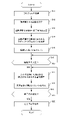
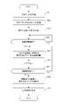
- FIG. 2 is a flowchart showing the operation of the analysis device 1.
- FIG. 3 is a diagram showing an example of a range of logical operations in the ladder program to be analyzed by the analysis device 1.
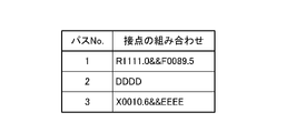
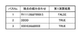
- FIG. 4 is a table showing an example of a combination of contacts in each path included in the range of logical operation shown in FIG.
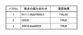
- FIG. 5 is a table showing an example of the result of the logical operation for each path shown in FIG.
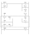
- FIG. 6 is an example of a diagram showing the result of the logical operation shown in FIG. 5 in a ladder program.
- FIG. 1 is a functional block diagram illustrating a function of the analysis device 1 according to the present embodiment.
- FIG. 2 is a flowchart showing the operation of the analysis device 1.
- FIG. 3 is a diagram showing an example of a range of logical operations in the ladder program to be analyzed by the analysis device 1.
- FIG. 4 is
- FIG. 7 is a table showing an example of the result of the first logical operation for each path shown in FIG.
- FIG. 8 is a table showing an example of the result of the second logical operation for each path shown in FIG.
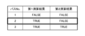
- FIG. 9 is a table showing the difference between the result of the first logical operation shown in FIG. 7 and the result of the second logical operation shown in FIG.
- FIG. 10 is an example of a diagram showing the differences shown in FIG. 9 in a ladder program.
- the analysis device 1 includes a control unit 11, a storage unit 12, and a display device 13.
- the control unit 11 is a part that controls the entire analysis device 1, and various programs in the present embodiment are executed by appropriately reading and executing various programs from a storage area such as a ROM, RAM, flash memory, or a hard disk (HDD). Realizes the function.
- the control unit 11 may be a CPU.
- the control unit 11 includes a program acquisition unit 111, a range setting unit 112, a start / end condition setting unit 113, a path analysis unit 114, a list generation unit 115, a logical operation unit 116, and a path output unit 117.
- the control unit 11 executes and analyzes the ladder program.
- the program acquisition unit 111 acquires a ladder program to be analyzed by the analysis device 1 from the storage unit 12 described later.
- the range setting unit 112 sets the range of the path to be the target of the logical operation by the logical operation unit 116 described later.
- the range setting unit 112 makes it possible to perform logical operations only on a part of the circuits, not all the circuits constituting the ladder program.
- the start / end condition setting unit 113 sets the start condition and the end condition of the logical operation.
- the start / end condition setting unit 113 indicates, for example, that "X0.0" in the ladder program is turned ON and that the start button instructing the start of the analysis of the ladder program is pressed in the analysis device 1. It may be a starting condition. Further, in the start / end condition setting unit 113, for example, "X0.0" in the ladder program is turned off, or the end button instructing the end of the analysis of the ladder program in the analysis device 1 is pressed. This may be the end condition.
- the path analysis unit 114 analyzes each path of the ladder program circuit. More specifically, the path analysis unit 114 identifies (reveals) all the paths included in the ladder program circuit.
- the list generation unit 115 lists the paths analyzed by the path analysis unit 114.
- the logical operation unit 116 performs a logical operation using the condition values of each combination of contacts included in each item of the list generated by the list generation unit 115.
- the list generation unit 115 and the logical operation unit 116 may be collectively referred to as a “contact combination acquisition unit”.
- the path output unit 117 outputs a path based on the calculation result by the logical operation unit 116. For example, the path output unit 117 may output only the path for which the operation result by the logical operation unit 116 is true. Alternatively, the path output unit 117 may output only the path for which the operation result by the logical operation unit 116 is false. Further, these output destinations may be the storage unit 12 described later or the display device 13.
- the path output unit 117 includes a difference comparison unit 118 and a comparison result output unit 119.
- the difference comparison unit 118 compares the results of the plurality of operations.
- the comparison result output unit 119 outputs the comparison result by the difference comparison unit 118 together with the path corresponding to each calculation result included in the comparison result.
- the storage unit 12 stores the ladder program acquired by the program acquisition unit 111, the path output by the path output unit 117, the comparison result output by the comparison result output unit 119 included in the path output unit 117, and the like. It is a storage device.
- the display device 13 displays a ladder program acquired by the program acquisition unit 111, a path output by the path output unit 117, a comparison result output by the comparison result output unit 119 included in the path output unit 117, and the like. It is a display device, and is realized by, for example, a liquid crystal monitor.
- step S11 the program acquisition unit 111 acquires the ladder program from the storage unit 12.
- step S12 the range setting unit 112 sets the range for logical operation.
- FIG. 3 shows an example of setting a range for logical operation.
- a range including a path including "R1111.0” and “F0089.5", a path including "DDDD”, and a path including "X0010.6” and “EEEE” is set. ..
- step S13 the start / end condition setting unit 113 sets the start condition and the end condition of the logical operation.
- step S14 the path analysis unit 114 analyzes the path of the ladder program included in the range of logical operation.
- step S15 the list generation unit 115 lists each analyzed path.
- FIG. 4 is an example of the list generated by the list generation unit 115.
- step S16 If the start condition is satisfied in step S16 (S16: YES), the process proceeds to step S17. If the start condition is not satisfied (S16: NO), the process returns to step S16.
- step S17 the logical operation unit 116 logically operates the condition value corresponding to the combination of contacts included in each item of the list.
- FIG. 5 shows an example of the result of a logical operation.
- step S18 the path output unit 117 outputs the path for which the calculation result is true.
- the path output unit 117 assumes that the path for which the calculation result is true is output to the display device 13, but the present invention is not limited to this.
- the path output unit 117 may output a path whose calculation result is false instead of the path whose calculation result is true.
- the output destination may be the storage unit 12 instead of the display device 13.
- step S19 If the end condition is satisfied in step S19 (S19: YES), the process proceeds to step S20. If the end condition is not satisfied (S19: NO), the process returns to step S17.
- step S20 the display device 13 displays the output content by the path output unit 117.
- FIG. 6 is a display example thereof, and FIG. 5 shows a path No. in which the calculation result is true. The path of 2 is highlighted (in FIG. 6, the path is shown by a thick line).
- the analysis device 1 not only outputs the path in which the calculation result is true, but also outputs the comparison result by the difference comparison unit 118 together with the path corresponding to each calculation result included in the comparison result. good.
- FIGS. 7 to 9 an example is shown in which the calculation result included in the comparison result is output together with the path corresponding to the comparison result.
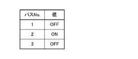
- FIG. 7 is a table showing an example of the first calculation result.
- the path No. The calculation result of 1 is "FALSE”
- the calculation result of 2 is "TRUE”
- the calculation result of 3 is "FALSE”.
- FIG. 8 is a table showing an example of the second calculation result.
- the path No. The calculation result of 1 is "FALSE”
- the calculation result of 2 is "FALSE”
- the calculation result of 3 is "FALSE”.
- the path No. The calculation result of 2 is changed from "TRUE" to "FALSE".
- FIG. 9 is a table showing the comparison result between the first calculation result and the second calculation result. As described above, the path No. The calculation result of 2 is "TRUE" in the first calculation result and "FALSE” in the second calculation result. In FIG. 9, the path Nos. The second column is surrounded by a thick line.
- FIG. 10 shows an example of a ladder program displayed by the display device 13 as a result of the comparison result being output to the display device 13 by the comparison result output unit 119.
- the path No. The path of 2 is highlighted (in FIG. 10, the path is shown by a thick line).
- the display device 13 may display the table of FIG. 9 instead of the ladder program shown in FIG.
- FIG. 11 is a functional block diagram illustrating the functions of the analysis device 1A according to the present embodiment.
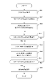
- FIG. 12 is a flowchart showing the operation of the analysis device 1A.
- FIG. 13 is a table showing the execution history of operations.
- the analysis device 1A according to the second embodiment mainly describes the components and operations different from those of the analysis device 1 according to the first embodiment, and the same components and operations are described. May be omitted.
- control unit 11A included in the analysis device 1A is different from the control unit 11 included in the analysis device 1 in that the execution history output unit 120 is further provided.
- FIG. 11 does not show the range setting unit 112, the start / end condition setting unit 113, the difference comparison unit 118, and the comparison result output unit 119 included in the control unit 11 of the analysis device 1 for the sake of simplification of the description. However, it may be configured to include one or more of these.
- the execution history output unit 120 outputs the path whose result of the logical operation has changed when the logical operation is executed a plurality of times, together with the execution history of each path.
- the output destination may be the storage unit 12 or the display device 13.
- step S31 the program acquisition unit 111 acquires the ladder program from the storage unit 12.
- step S32 the path analysis unit 114 analyzes the path of the ladder program.
- step S33 the list generation unit 115 lists each analyzed path.
- step S34 When the logical operation is started in step S34 (S34: YES), the process proceeds to step S35. If the logical operation has not started yet (S34: NO), the process returns to step S34.
- step S35 the logical operation unit 116 logically operates the condition value corresponding to the combination of contacts included in each item of the list.
- step S36 the path output unit 117 outputs the path together with the calculation result.
- the path output unit 117 outputs the path together with the calculation result to the execution history output unit 120.
- step S37 When the logical operation is terminated in step S37 (S37: YES), the process proceeds to step S38. If the logical operation has not been completed yet (S37: NO), the process returns to step S35.
- step S38 the execution history output unit 120 outputs the paths whose logical operation results have changed, together with the execution history for each path.
- the execution history output unit 120 is supposed to output to the display device 13, but the present invention is not limited to this, and the execution history output unit 120 may output to the storage unit 12.
- step S39 the display device 13 displays the content output from the execution history output unit 120.
- FIG. 13 is a display example thereof.
- Path No. For path 1, the operation result at the time of the first logical operation is "TRUE”, the operation result at the time of the second logical operation is "FALSE”, and the operation result at the time of the third logical operation is "FALSE”.
- the calculation result of is "FALSE”. That is, the path No.
- the path 1 is highlighted because the calculation result has changed (in FIG. 13, the column is surrounded by a thick line).
- FIG. 14 is a functional block diagram illustrating the functions of the analysis device 1B according to the present embodiment.
- FIG. 15 is a flowchart showing the operation of the analysis device 1B.
- FIG. 16 shows an example in which a dummy output coil is installed in each path constituting the ladder program.
- FIG. 17 is a table showing an example of the output result for each path shown in FIG.
- FIG. 18 is an example of a diagram showing the output result shown in FIG. 17 in a ladder program.
- the analysis device 1B according to the third embodiment mainly describes the components and operations different from those of the analysis device 1 according to the first embodiment, and the same components and operations are described. May be omitted.
- control unit 11B included in the analysis device 1B does not include the logical operation unit 116 as compared with the control unit 11 included in the analysis device 1, and instead includes the coil / command installation unit 121.
- the coil / instruction installation unit 121 installs a dummy output coil or instruction in each path for each path analyzed by the path analysis unit 114.
- the coil / command installation unit 121 in this embodiment constitutes a part or all of the “contact combination acquisition unit”.
- the path output unit 117A outputs a path based on the output result from the dummy output coil or instruction installed by the coil / command installation unit 121.
- the start / end condition setting unit 113 sets the start condition and end condition of the output of the output coil or the command.
- the ladder program execution unit 122 that executes the ladder program executes the output coil or instruction installed by the coil / instruction installation unit 121. Specifically, the ladder program execution unit 122 starts the output of the output coil or the instruction when the start condition is satisfied, and ends the output of the output coil or the instruction when the end condition is satisfied.
- the ladder program execution unit is also provided as a functional configuration in the control unit 11 of the first embodiment and the control unit 11A of the second embodiment.
- the range setting unit 112 sets the range of the path that is the target of the output coil or the output of the command.
- the path analysis unit 114 analyzes each path within the set range.
- step S51 the program acquisition unit 111 acquires the ladder program from the storage unit 12.
- step S52 the path analysis unit 114 analyzes the path of the ladder program.
- step S53 the coil / instruction installation unit 121 installs a dummy output coil or instruction in each analyzed path.
- FIG. 16 is an installation example of the output coils D1 to D3.
- step S54 If the ladder program execution unit 122 starts executing the ladder program in step S54 (S54: YES), the process proceeds to step S55. If the ladder program execution unit 122 has not yet started the execution of the ladder program (S54: NO), the process returns to step S54.
- step S55 the path output unit 117A acquires the output result from the output coil or the instruction.
- FIG. 17 is a table showing an example of the output result.
- step S56 the path output unit 117A outputs the path for which the output result from the output coil or the instruction is true.
- the path output unit 117A may output a path whose output result is false instead of the path whose output result is true.
- the path output unit 117A is supposed to output to the display device 13, but is not limited to this, and the output destination may be the storage unit 12.
- step S57 when the ladder program execution unit 122 ends the execution of the ladder program (S57: YES), the process proceeds to step S58. If the ladder program execution unit 122 has not yet finished executing the ladder program (S57: NO), the process returns to step S55.
- step S58 the display device 13 displays the content output from the path output unit 117A.
- FIG. 18 is a display example thereof, and FIG. 17 shows a path No. in which the output result is turned ON. The path of 2 is highlighted (in FIG. 18, the path is shown by a thick line).
- the analysis device is based on a path analysis unit 114 that analyzes each path of the ladder program circuit, a contact combination acquisition unit that acquires a combination of contacts of each analyzed path, and a calculation result of a condition value for each combination. It is provided with a path output unit 117 that outputs a path.
- the analysis device is provided with an execution history output unit 120 that outputs a path in which the result of the logical operation has changed when the logical operation is executed a plurality of times together with the execution history of each path. You can check the execution history of the ladder program without using such functions.
Landscapes
- Engineering & Computer Science (AREA)
- Theoretical Computer Science (AREA)
- Physics & Mathematics (AREA)
- General Physics & Mathematics (AREA)
- General Engineering & Computer Science (AREA)
- Computer Hardware Design (AREA)
- Quality & Reliability (AREA)
- Automation & Control Theory (AREA)
- Programmable Controllers (AREA)
- Software Systems (AREA)
Abstract
Description
以下、本発明の第1実施形態について図1~図10を参照することにより説明する。図1は、本実施形態に係る解析装置1の機能について説明する機能ブロック図である。図2は、解析装置1の動作を示すフローチャートである。図3は、解析装置1が解析対象とするラダープログラムのうち、論理演算する範囲の例を示す図である。図4は、図3に示す論理演算する範囲に含まれる各パスにおける接点の組み合わせの例を示す表である。図5は、図4に示す各パスに対する論理演算の結果の例を示す表である。図6は、図5に示された論理演算の結果をラダープログラムにおいて示す図の例である。図7は、図3に示す各パス毎の第1の論理演算の結果の例を示す表である。図8は、図3に示す各パス毎の第2の論理演算の結果の例を示す表である。図9は、図7に示す第1の論理演算の結果と図8に示す第2の論理演算の結果との差分を示す表である。図10は、図9に示される差分をラダープログラムにおいて示す図の例である。
図1に示すように、本実施形態に係る解析装置1は、制御部11と、記憶部12と、表示装置13とを備える。
差分比較部118は、論理演算部116によって、所定のパスが複数回論理演算された場合、これら複数回の演算結果を比較する。
比較結果出力部119は、差分比較部118による比較結果を、比較結果に含まれる各々の演算結果が対応するパスと共に出力する。
以下、図2のフローチャートと、図3~図10に例示される図を参照することにより、本実施形態に係る解析装置1の動作について説明する。
以下、本発明の第2実施形態について図11~図13を参照することにより説明する。図11は、本実施形態に係る解析装置1Aの機能について説明する機能ブロック図である。図12は、解析装置1Aの動作を示すフローチャートである。図13は、演算の実行履歴を示す表である。なお、以下では説明の簡略化のため、主として、第2実施形態に係る解析装置1Aが、第1実施形態に係る解析装置1と異なる構成要素や動作について記載し、同一の構成要素や動作については、省略することがある。
図11を参照すると、解析装置1Aが備える制御部11Aは、解析装置1が備える制御部11に比較して、実行履歴出力部120を更に備える点で異なる。なお、図11では、説明の簡略化のため、解析装置1の制御部11が備える範囲設定部112、開始・終了条件設定部113、差分比較部118、比較結果出力部119を記載していないが、これらのうち1以上を備える構成としてもよい。
以下、図12のフローチャートと、図13に例示される表を参照することにより、本実施形態に係る解析装置1Aの動作について説明する。
以下、本発明の第3実施形態について図14~図18を参照することにより説明する。図14は、本実施形態に係る解析装置1Bの機能について説明する機能ブロック図である。図15は、解析装置1Bの動作を示すフローチャートである。図16は、ラダープログラムを構成する各パスにダミーの出力コイルを設置した例である。図17は、図3に示す各パス毎の出力結果の例を示す表である。図18は、図17に示される出力結果をラダープログラムにおいて示す図の例である。なお、以下では説明の簡略化のため、主として、第3実施形態に係る解析装置1Bが、第1実施形態に係る解析装置1と異なる構成要素や動作について記載し、同一の構成要素や動作については、省略することがある。
図14を参照すると、解析装置1Bが備える制御部11Bは、解析装置1が備える制御部11に比較して、論理演算部116を備えず、その代わりに、コイル・命令設置部121を備える。
以下、図15のフローチャートと、図16~図18の図を参照することにより、本実施形態に係る解析装置1Bの動作について説明する。
本発明に係る解析装置は、ラダープログラム回路の各パスを解析するパス解析部114と、解析した各パスの接点の組み合わせを取得する接点組み合わせ取得部と、組み合わせ毎の条件値の演算結果に基づいてパスを出力するパス出力部117とを備える。
11 制御部
12 記憶部
13 表示装置
111 プログラム取得部
112 範囲設定部
113 開始・終了条件設定部
114 パス解析部
115 リスト生成部
116 論理演算部
117,117A パス出力部
118 差分比較部
119 比較結果出力部
120 実行履歴出力部
121 コイル・命令設置部
122 ラダープログラム実行部
Claims (12)
- ラダープログラム回路の各パスを解析するパス解析部と、
解析した各パスの接点の組み合わせを取得する接点組み合わせ取得部と、
前記組み合わせ毎の条件値の演算結果に基づいてパスを出力するパス出力部とを備える、解析装置。 - 前記接点組み合わせ取得部は、取得された接点の組み合わせ毎の条件値について論理演算を行う論理演算部を備える、請求項1に記載の解析装置。
- 前記接点組み合わせ取得部は、取得された接点の組み合わせ毎に、各パスへ出力コイル又は命令を設置するコイル・命令設置部を備え、
前記パス出力部は、設置された出力コイル又は命令の出力に基づいて、パスを出力する、請求項1に記載の解析装置。 - 前記論理演算の開始条件及び終了条件を設定する開始・終了条件設定部を更に備え、
前記論理演算部は、前記開始条件が成立した際に前記論理演算を開始し、前記終了条件が成立した際に前記論理演算を終了する、請求項2に記載の解析装置。 - 前記論理演算の対象となるパスの範囲を設定する範囲設定部を更に備え、
前記パス解析部は、設定された範囲内の各パスを解析する、請求項2又は請求項4に記載の解析装置。 - 前記パス出力部は、
前記論理演算を複数回実行した際、前記論理演算部による複数の演算結果を比較する差分比較部と、
前記差分比較部による比較結果を出力する比較結果出力部とを備える、請求項2、請求項4又は請求項5に記載の解析装置。 - 前記論理演算を複数回実行した際、前記論理演算の結果に変化のあったパスを、パス毎の実行履歴と共に出力する実行履歴出力部を更に備える、請求項2、請求項4、請求項5又は請求項6に記載の解析装置。
- 前記出力コイル又は命令の出力の開始条件及び終了条件を設定する開始・終了条件設定部と、
ラダープログラムを実行するラダープログラム実行部と、を更に備え、
前記ラダープログラム実行部は、前記開始条件が成立した際に前記出力コイル又は命令の出力を開始し、前記終了条件が成立した際に前記出力コイル又は命令の出力を終了する、請求項3に記載の解析装置。 - 前記出力コイル又は命令の出力の対象となるパスの範囲を設定する範囲設定部を更に備え、
前記パス解析部は、設定された範囲内の各パスを解析する、請求項3又は請求項8に記載の解析装置。 - 前記パス出力部は、
前記出力コイル又は命令の出力を複数回実行した際、前記出力コイル又は命令の出力結果を比較する差分比較部と、
前記差分比較部による比較結果を出力する比較結果出力部とを備える、請求項3、請求項8又は請求項9に記載の解析装置。 - 前記出力コイル又は命令の出力を複数回実行した際、前記出力コイル又は命令の出力の結果に変化のあったパスを、パス毎の実行履歴と共に出力する実行履歴出力部を更に備える、請求項3、請求項8、請求項9又は請求項10に記載の解析装置。
- 前記パス出力部による出力結果を表示する表示装置を更に備える、請求項1から請求項11のいずれか1項に記載の解析装置。
Priority Applications (4)
| Application Number | Priority Date | Filing Date | Title |
|---|---|---|---|
| JP2022571374A JP7601906B2 (ja) | 2020-12-21 | 2021-12-16 | ラダープログラム解析装置 |
| US18/255,348 US12450149B2 (en) | 2020-12-21 | 2021-12-16 | Ladder program analysis device used in a programmable logic controller (PLC) |
| DE112021005500.3T DE112021005500T5 (de) | 2020-12-21 | 2021-12-16 | Kontaktplanprogramm-Analysevorrichtung |
| CN202180083811.0A CN116615720A (zh) | 2020-12-21 | 2021-12-16 | 梯形图程序解析装置 |
Applications Claiming Priority (2)
| Application Number | Priority Date | Filing Date | Title |
|---|---|---|---|
| JP2020211354 | 2020-12-21 | ||
| JP2020-211354 | 2020-12-21 |
Publications (1)
| Publication Number | Publication Date |
|---|---|
| WO2022138442A1 true WO2022138442A1 (ja) | 2022-06-30 |
Family
ID=82159310
Family Applications (1)
| Application Number | Title | Priority Date | Filing Date |
|---|---|---|---|
| PCT/JP2021/046507 Ceased WO2022138442A1 (ja) | 2020-12-21 | 2021-12-16 | ラダープログラム解析装置 |
Country Status (5)
| Country | Link |
|---|---|
| US (1) | US12450149B2 (ja) |
| JP (1) | JP7601906B2 (ja) |
| CN (1) | CN116615720A (ja) |
| DE (1) | DE112021005500T5 (ja) |
| WO (1) | WO2022138442A1 (ja) |
Citations (3)
| Publication number | Priority date | Publication date | Assignee | Title |
|---|---|---|---|---|
| JPS605347A (ja) * | 1983-06-23 | 1985-01-11 | Fujitsu Ltd | 複数プロセツサ用スタテイツクトレ−ス装置 |
| JPH10283005A (ja) * | 1997-04-04 | 1998-10-23 | Mitsubishi Electric Corp | シーケンスプログラムの表示方法、および、実行方法 |
| JP2015170009A (ja) * | 2014-03-05 | 2015-09-28 | 株式会社東芝 | 表示情報生成装置、プログラム実行状況表示システム、方法およびプログラム |
Family Cites Families (12)
| Publication number | Priority date | Publication date | Assignee | Title |
|---|---|---|---|---|
| US5781776A (en) * | 1995-11-01 | 1998-07-14 | Allen Bradley Company, Inc. | Industrial controller permitting program editing during program execution |
| US20120072777A1 (en) * | 2009-05-27 | 2012-03-22 | Mitsubishi Electric Corporation | Debugging device, debugging method, and computer program for sequence program |
| DE112012007174T5 (de) * | 2012-11-26 | 2015-08-06 | Mitsubishi Electric Corporation | Kontaktplan-Anzeigevorrichtung und Kontaktplan-Anzeigeverfahren |
| JP2015149004A (ja) * | 2014-02-07 | 2015-08-20 | 富士電機株式会社 | ラダー図試験データ作成装置 |
| JP6309927B2 (ja) * | 2015-09-16 | 2018-04-11 | ファナック株式会社 | Ncプログラム運転と連動した関連信号の自動トレース機能を有する数値制御装置 |
| JP6827340B2 (ja) | 2017-02-17 | 2021-02-10 | 三菱重工エンジニアリング株式会社 | ソフトウェア試験装置、ソフトウェア試験システム、ソフトウェア試験方法およびプログラム |
| JP6568152B2 (ja) * | 2017-06-30 | 2019-08-28 | ファナック株式会社 | 数値制御装置 |
| WO2020105173A1 (ja) * | 2018-11-22 | 2020-05-28 | 三菱電機株式会社 | データ制御装置、プログラマブルロジックコントローラ及びデータ制御方法 |
| WO2020174627A1 (ja) * | 2019-02-27 | 2020-09-03 | 三菱電機株式会社 | 設計支援装置、設計支援方法および設計支援プログラム |
| EP3715975B1 (en) * | 2019-03-28 | 2023-03-01 | Mitsubishi Electric R&D Centre Europe B.V. | Method and apparatus for analysing a ladder program |
| JP7277292B2 (ja) * | 2019-07-08 | 2023-05-18 | ファナック株式会社 | Plc装置 |
| US11409257B2 (en) * | 2019-10-03 | 2022-08-09 | Keyence Corporation | Setting device that sets a programmable logic controller and PLC system that collects control data and a dashboard for displaying control data |
-
2021
- 2021-12-16 JP JP2022571374A patent/JP7601906B2/ja active Active
- 2021-12-16 US US18/255,348 patent/US12450149B2/en active Active
- 2021-12-16 CN CN202180083811.0A patent/CN116615720A/zh active Pending
- 2021-12-16 WO PCT/JP2021/046507 patent/WO2022138442A1/ja not_active Ceased
- 2021-12-16 DE DE112021005500.3T patent/DE112021005500T5/de active Pending
Patent Citations (3)
| Publication number | Priority date | Publication date | Assignee | Title |
|---|---|---|---|---|
| JPS605347A (ja) * | 1983-06-23 | 1985-01-11 | Fujitsu Ltd | 複数プロセツサ用スタテイツクトレ−ス装置 |
| JPH10283005A (ja) * | 1997-04-04 | 1998-10-23 | Mitsubishi Electric Corp | シーケンスプログラムの表示方法、および、実行方法 |
| JP2015170009A (ja) * | 2014-03-05 | 2015-09-28 | 株式会社東芝 | 表示情報生成装置、プログラム実行状況表示システム、方法およびプログラム |
Also Published As
| Publication number | Publication date |
|---|---|
| JPWO2022138442A1 (ja) | 2022-06-30 |
| DE112021005500T5 (de) | 2024-01-18 |
| US12450149B2 (en) | 2025-10-21 |
| CN116615720A (zh) | 2023-08-18 |
| JP7601906B2 (ja) | 2024-12-17 |
| US20240028333A1 (en) | 2024-01-25 |
Similar Documents
| Publication | Publication Date | Title |
|---|---|---|
| US8453106B2 (en) | Graphical user interface for exploring source code execution behavior | |
| US10445225B2 (en) | Command coverage analyzer | |
| CN105279093A (zh) | 软件测试方法、装置及设备 | |
| JP6351906B1 (ja) | デバッグ装置 | |
| JPH10320234A (ja) | ソフトウェアの自動テスト方法 | |
| JP2004004050A (ja) | 試験実行システムを供給する製品および試験実行システムを動作させる方法 | |
| WO2022138442A1 (ja) | ラダープログラム解析装置 | |
| JP6275009B2 (ja) | 試験装置及び試験プログラム | |
| JP6978458B2 (ja) | シーケンスプログラムのトレースに用いるシーケンスプログラム処理装置 | |
| JP7750409B2 (ja) | 情報処理装置、試験方法、及び試験プログラム | |
| KR101999321B1 (ko) | 프로그램 검증 시스템 및 검증 방법 | |
| WO2020065826A1 (ja) | バリデーション装置、バリデーション方法およびバリデーションプログラム | |
| JP2019106107A (ja) | プログラム、情報処理装置及び画面テストシステム | |
| KR101038877B1 (ko) | 테스트 절차 생성 시스템, 그 컴퓨터 구현 방법 및 컴퓨터 판독가능 기록 매체 | |
| JP2010025589A (ja) | 試験装置及び試験プログラム | |
| US20240211385A1 (en) | Test support apparatus, test support method and program | |
| JP2009223804A (ja) | 端末装置、及び検査方法 | |
| JP2019040280A (ja) | 出力プログラム、出力方法および情報処理装置 | |
| JP2005090959A (ja) | 制御プログラムおよび測定システム | |
| WO2025186989A1 (ja) | プログラム、処理装置、及び方法 | |
| JP5680040B2 (ja) | 移動体通信端末試験システム及び移動体通信端末試験方法 | |
| WO2018123039A1 (ja) | プログラム比較装置およびプログラム差分照合方法 | |
| JP2007128456A (ja) | プログラム管理装置 | |
| CN116737572A (zh) | 一种基于互联网的应用软件测试方法、系统及存储介质 | |
| JP4888148B2 (ja) | 半導体試験装置 |
Legal Events
| Date | Code | Title | Description |
|---|---|---|---|
| 121 | Ep: the epo has been informed by wipo that ep was designated in this application |
Ref document number: 21910590 Country of ref document: EP Kind code of ref document: A1 |
|
| ENP | Entry into the national phase |
Ref document number: 2022571374 Country of ref document: JP Kind code of ref document: A |
|
| WWE | Wipo information: entry into national phase |
Ref document number: 18255348 Country of ref document: US |
|
| WWE | Wipo information: entry into national phase |
Ref document number: 202180083811.0 Country of ref document: CN |
|
| WWE | Wipo information: entry into national phase |
Ref document number: 112021005500 Country of ref document: DE |
|
| 122 | Ep: pct application non-entry in european phase |
Ref document number: 21910590 Country of ref document: EP Kind code of ref document: A1 |
|
| WWG | Wipo information: grant in national office |
Ref document number: 18255348 Country of ref document: US |