WO2022138283A1 - バーハンドル車両の前部構造 - Google Patents
バーハンドル車両の前部構造 Download PDFInfo
- Publication number
- WO2022138283A1 WO2022138283A1 PCT/JP2021/045814 JP2021045814W WO2022138283A1 WO 2022138283 A1 WO2022138283 A1 WO 2022138283A1 JP 2021045814 W JP2021045814 W JP 2021045814W WO 2022138283 A1 WO2022138283 A1 WO 2022138283A1
- Authority
- WO
- WIPO (PCT)
- Prior art keywords
- master cylinder
- handlebar
- vehicle body
- brake
- lever
- Prior art date
- Legal status (The legal status is an assumption and is not a legal conclusion. Google has not performed a legal analysis and makes no representation as to the accuracy of the status listed.)
- Ceased
Links
Images


Classifications
-
- B—PERFORMING OPERATIONS; TRANSPORTING
- B62—LAND VEHICLES FOR TRAVELLING OTHERWISE THAN ON RAILS
- B62K—CYCLES; CYCLE FRAMES; CYCLE STEERING DEVICES; RIDER-OPERATED TERMINAL CONTROLS SPECIALLY ADAPTED FOR CYCLES; CYCLE AXLE SUSPENSIONS; CYCLE SIDECARS, FORECARS, OR THE LIKE
- B62K23/00—Rider-operated controls specially adapted for cycles, i.e. means for initiating control operations, e.g. levers, grips
- B62K23/02—Rider-operated controls specially adapted for cycles, i.e. means for initiating control operations, e.g. levers, grips hand actuated
- B62K23/06—Levers
-
- B—PERFORMING OPERATIONS; TRANSPORTING
- B60—VEHICLES IN GENERAL
- B60T—VEHICLE BRAKE CONTROL SYSTEMS OR PARTS THEREOF; BRAKE CONTROL SYSTEMS OR PARTS THEREOF, IN GENERAL; ARRANGEMENT OF BRAKING ELEMENTS ON VEHICLES IN GENERAL; PORTABLE DEVICES FOR PREVENTING UNWANTED MOVEMENT OF VEHICLES; VEHICLE MODIFICATIONS TO FACILITATE COOLING OF BRAKES
- B60T7/00—Brake-action initiating means
- B60T7/02—Brake-action initiating means for personal initiation
- B60T7/08—Brake-action initiating means for personal initiation hand actuated
-
- B—PERFORMING OPERATIONS; TRANSPORTING
- B62—LAND VEHICLES FOR TRAVELLING OTHERWISE THAN ON RAILS
- B62K—CYCLES; CYCLE FRAMES; CYCLE STEERING DEVICES; RIDER-OPERATED TERMINAL CONTROLS SPECIALLY ADAPTED FOR CYCLES; CYCLE AXLE SUSPENSIONS; CYCLE SIDECARS, FORECARS, OR THE LIKE
- B62K11/00—Motorcycles, engine-assisted cycles or motor scooters with one or two wheels
- B62K11/14—Handlebar constructions, or arrangements of controls thereon, specially adapted thereto
-
- B—PERFORMING OPERATIONS; TRANSPORTING
- B62—LAND VEHICLES FOR TRAVELLING OTHERWISE THAN ON RAILS
- B62L—BRAKES SPECIALLY ADAPTED FOR CYCLES
- B62L3/00—Brake-actuating mechanisms; Arrangements thereof
- B62L3/02—Brake-actuating mechanisms; Arrangements thereof for control by a hand lever
- B62L3/023—Brake-actuating mechanisms; Arrangements thereof for control by a hand lever acting on fluid pressure systems
-
- B—PERFORMING OPERATIONS; TRANSPORTING
- B62—LAND VEHICLES FOR TRAVELLING OTHERWISE THAN ON RAILS
- B62M—RIDER PROPULSION OF WHEELED VEHICLES OR SLEDGES; POWERED PROPULSION OF SLEDGES OR SINGLE-TRACK CYCLES; TRANSMISSIONS SPECIALLY ADAPTED FOR SUCH VEHICLES
- B62M25/00—Actuators for gearing speed-change mechanisms specially adapted for cycles
- B62M25/02—Actuators for gearing speed-change mechanisms specially adapted for cycles with mechanical transmitting systems, e.g. cables, levers
- B62M25/04—Actuators for gearing speed-change mechanisms specially adapted for cycles with mechanical transmitting systems, e.g. cables, levers hand actuated
Definitions
- the present invention relates to a front structure of a bar handle vehicle such as a motorcycle, and more particularly to a front structure of a bar handle vehicle provided with a clutch lever and a brake lever in front of the vehicle body of a steering handle bar.
- a clutch lever for operating a clutch device is provided in the vicinity of the handlebar, and a brake operator for rear wheel braking is provided in the vicinity of the clutch lever ().
- a clutch lever for operating a clutch device is provided in the vicinity of the handlebar, and a brake operator for rear wheel braking is provided in the vicinity of the clutch lever ().
- the occupant is configured to operate the clutch lever and the brake lever by operating the left hand, and when operating the brake, the brake lever is operated by the thumb of the left hand attached to the grip of the handlebar.
- the clutch lever is grasped with fingers such as the index finger and the middle finger other than the thumb of the left hand.
- the brake operation was not easy because the brake lever had to be pressed with the thumb while grasping the grip.
- an object of the present invention is to provide a front structure of a bar handle vehicle in which the clutch operation and the brake operation can be easily performed with one hand of the occupant.
- the front structure of the bar handle vehicle of the present invention connects and connects a driving force transmission path to and from the wheels around a grip provided at the side end of the steering handle bar.
- the brake device comprises a cylinder hole for accommodating a piston.
- a hydraulic master cylinder and the brake lever for operating the piston are provided, and the clutch lever and the brake lever extend in front of the vehicle body of the grip along the grip and in the same rotation direction.
- the clutch lever is rotatably provided and is characterized in that the clutch lever is arranged above the vehicle body with respect to the brake lever.
- the central axis of the cylinder hole is mounted in parallel with the central axis of the handlebar.
- the hydraulic master cylinder is mounted so that the inclination angle of the central axis of the cylinder hole with respect to the central axis of the handlebar can be adjusted.
- the brake device is attached to the handlebar via the master cylinder mounting bracket, and the master cylinder mounting bracket extends from the handlebar mounting portion to be attached to the handlebar and the handlebar mounting portion to the lower part of the vehicle body. It is preferable that the master cylinder mounting portion is provided and the hydraulic pressure master cylinder is mounted on the master cylinder mounting portion.
- the hydraulic master cylinder is provided with a vehicle body mounting bracket that is long in the vehicle body inside / outside direction and is attached to the master cylinder mounting bracket, and the vehicle body mounting bracket is formed with a circular first bolt insertion hole inside the vehicle body.
- a second bolt insertion hole formed by a long arc-shaped elongated hole in the vertical direction of the vehicle body centered on the first bolt insertion hole was formed on the outside of the vehicle body, and was inserted into the first bolt insertion hole.
- the clutch lever and the brake lever are provided in front of the vehicle body of the grip so as to extend along the grip and rotatably in the same rotation direction, and further, the clutch lever is provided on the vehicle body rather than the brake lever. Since it is arranged above, the occupant can easily operate the clutch or the brake by grasping the clutch lever or the brake lever with a finger other than the thumb of the left hand while grasping the grip.
- the central axis of the cylinder hole is attached in parallel with the central axis of the handlebar, so that an effective space can be secured around the handlebar and the layout is improved.
- the hydraulic master cylinder is mounted so that the inclination angle of the central axis of the cylinder hole with respect to the central axis of the handlebar can be adjusted, the layout of the brake lever can be improved and the operation position of the brake lever can be improved. Can be adjusted.
- the brake device is attached to the handlebar via the master cylinder mounting bracket, and the master cylinder mounting bracket has a handlebar mounting portion mounted on the handlebar and a master cylinder extending downward from the handlebar mounting portion.
- the clutch lever can be arranged above the vehicle body with a simple structure.
- the hydraulic master cylinder is provided with a long vehicle body mounting bracket attached to the master cylinder mounting bracket in the inward and outward directions of the vehicle body, and the vehicle body mounting bracket has a circular first bolt insertion hole on the inside of the vehicle body and the first bolt on the outside of the vehicle body.
- a second bolt insertion hole formed by a long arc-shaped long hole in the vertical direction of the vehicle body centered on the 1-bolt insertion hole is provided, and a mounting bolt inserted into the first bolt insertion hole and a second bolt are provided.
- the hydraulic master cylinder is attached to the master cylinder mounting bracket by fastening the mounting bolt inserted at any position of the insertion hole to the master cylinder mounting bracket, and is inserted into the second bolt insertion hole.
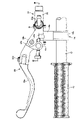
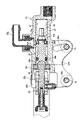
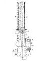
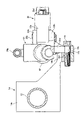
- FIG. 2 is a sectional view taken along line III-III of FIG. It is explanatory drawing which showed the mounting state of the brake device which shows one embodiment of this invention by omitting the clutch device. It is explanatory drawing which showed the state which the brake device was attached to the handlebar by inclining the central axis of a cylinder hole with respect to the central axis of a handlebar, omitting the clutch device. It is sectional drawing of the main part of the front structure of the bar handle vehicle which shows the example of one embodiment of this invention.
- FIGS. 1 to 6 are views showing an example of a front structure of the bar handle vehicle of the present invention.
- a front fork 11 that supports the front wheels is provided on the front portion of the bar handlebar vehicle, and steering wheelbars 12 and 12 are attached to the right side and the left side of the front fork 11.
- Rubber grips 13 and 13 gripped by the occupant are attached to the ends of the handlebars 12 and 12, respectively.
- the handlebar on the right side is equipped with a braking device that supplies hydraulic pressure to the front wheel brakes (not shown).
- a master cylinder mounting bracket 14 for mounting the hydraulic master cylinder 22 of the brake device 21 that supplies hydraulic pressure to the rear wheel brake is attached to the front fork side.
- a clutch lever 31 for pulling a wire cable connected to a clutch device for connecting and disconnecting a driving force transmission path between an engine and a wheel rotates It is installed as possible.
- the clutch lever 31 has a clutch gripping operation unit 31a, which is gripped and operated by an occupant, extending in front of the vehicle body of the grip 13 along the grip 13.
- the master cylinder mounting bracket 14 includes a handlebar mounting portion 14a that is mounted on the handlebar 12, and a master cylinder mounting portion 14b that extends downward from the handlebar mounting portion 14a to the lower part of the vehicle body.
- the master cylinder mounting portion 14b has a long mounting surface 14c formed on the front side of the vehicle body in the inward and outward directions of the vehicle body, and female screw holes 14d and 14d for fastening the mounting bolts 15 and 15 are arranged side by side on the mounting surface 14c. There is.
- the brake device 21 includes a hydraulic master cylinder 22, a brake lever 23 attached to the hydraulic master cylinder 22, and a push rod 24 interposed between them.
- the hydraulic master cylinder 22 is provided with a bottomed cylinder hole 22a inside, and is provided with a vehicle body mounting bracket 22b that protrudes from the lower side wall toward the lower side of the vehicle body and is long in the vehicle body inside / outside direction.
- the vehicle body mounting bracket 22b has a circular first bolt insertion hole 22c on the outside of the vehicle body on the brake lever 23 side, and a vehicle body vertical direction centered on the first bolt insertion hole 22c on the inside of the vehicle body on the front fork 11 side.
- the second bolt insertion hole 22d formed by a long arc-shaped long hole is formed at a position corresponding to the female screw holes 14d and 14d, respectively.
- the central axis CL1 of the cylinder hole 22a and the central axis CL2 of the handlebar 12 are parallel to each other by inserting the mounting bolt 15 into the lower end of the second bolt insertion hole 22d. It is installed so that it becomes.
- the hydraulic master cylinder 22 is attached so that the central axis CL1 of the cylinder hole 22a and the central axis CL2 of the handlebar are parallel to each other, but it is attached to the second bolt insertion hole 22d.
- the inclination angle of the central axis CL1 of the cylinder hole 22a with respect to the central axis CL2 of the handlebar 12 can be adjusted. For example, as shown in FIG. 5, if the mounting bolt 15 is inserted through the upper end of the second bolt insertion hole 22d, the inclination angle of the central axis CL1 of the cylinder hole 22a with respect to the central axis CL2 of the handlebar 12 is maximized. In this state, the hydraulic master cylinder 22 can be attached to the handlebar 12.
- a piston 25 is inserted into the cylinder hole 22a with the primary cup 26a and the secondary cup 26b fitted therein, and a hydraulic chamber 27 is defined between the piston 25 and the bottom wall of the cylinder hole 22a.
- a return spring 28 is contracted between the bottom wall of the cylinder hole 22a and the piston 25, and the elastic force of the return spring 28 constantly urges the piston 25 in the opening direction of the cylinder hole 22a to push the rod.
- the retreat limit is restricted by the contact of the tip portion 24a of the 24, and a ring 29 for preventing the piston from coming off is attached to the opening of the cylinder hole 22a.
- a relief port 22e and a supply port 22f are provided on the upper side wall of the hydraulic master cylinder 22 so as to communicate with the cylinder hole 22a, and both ports 22e and 22f are provided with a connector 22g to which a reservoir hose is connected.
- the hydraulic fluid flows between the cylinder hole 22a and the reservoir.
- a pair of upper and lower lever holders 22h and 22h are projected from the cylinder hole opening side end of the hydraulic master cylinder 22 with a predetermined gap, and the rotation base 23a of the brake lever 23 pivots to the lever holders 22h and 22h. It is rotatably attached to the shaft via 23b.
- the brake lever 23 includes the rotation base portion 23a rotatably connected to the lever holders 22h and 22h, and a brake grip operation portion 23c that is gripped and operated by an occupant. It is connected to the portion 23c by a connecting bolt 23d. Further, the brake lever 23 and the clutch lever 31 are provided so as to be rotatable in the same rotation direction, and the master cylinder mounting portion 14b of the master cylinder mounting bracket 14 to which the hydraulic pressure master cylinder 22 is mounted extends downward to the vehicle body. Since it is out, the clutch lever 31 is arranged above the vehicle body with respect to the brake lever 23.
- the brake device 21 is attached to the handlebar 12 via the master cylinder mounting bracket 14, and the master cylinder mounting bracket 14 has a master cylinder mounting portion 14b for mounting the hydraulic master cylinder 22 extending downward to the vehicle body. Therefore, the clutch lever 31 can be arranged above the vehicle body above the brake lever 23 with a simple structure. Further, since the central axis CL1 of the cylinder hole 22a of the hydraulic pressure master cylinder 22 and the central axis CL2 of the handlebar 12 are arranged in parallel, an effective space can be secured around the handlebar 12. , The layout is improved.
- the hydraulic pressure master cylinder 22 can adjust the inclination angle of the central axis CL1 of the cylinder hole 22a with respect to the central axis CL2 of the handlebar 12, the layout of the brake lever 23 can be improved and the layout of the brake lever 23 can be improved. The operating position of the brake lever 23 can be adjusted. Further, since the tilt angle of the central axis CL1 of the cylinder hole 22a can be adjusted by changing the position where the mounting bolt 15 is inserted into the second bolt insertion hole 22d of the vehicle body mounting bracket 22b, the tilt angle can be adjusted. Can be easily performed.
- the present invention is not limited to the case where the clutch lever pulls the wire cable to operate the clutch device as in the above-described embodiment, but the clutch lever is attached to the hydraulic master cylinder to operate the clutch device by hydraulic pressure. It may be a thing. Further, the hydraulic master cylinder may be attached to the handlebar in a state where the inclination angle of the central axis CL1 of the cylinder hole cannot be adjusted.
- Brake grip operation part, 23d Connecting bolt, 24 ... Push rod, 24a ... Tip part, 25 ... Piston, 26a ... Primary cup, 26b ... Secondary cup, 27 ... Hydraulic chamber, 28 ... Return spring, 29 ... Ring, 31 ... Clutch lever, 31a ... Clutch grip operation unit
Landscapes
- Engineering & Computer Science (AREA)
- Mechanical Engineering (AREA)
- Physics & Mathematics (AREA)
- Fluid Mechanics (AREA)
- Transportation (AREA)
- Chemical & Material Sciences (AREA)
- Combustion & Propulsion (AREA)
- Steering Devices For Bicycles And Motorcycles (AREA)
- Transmission Of Braking Force In Braking Systems (AREA)
Abstract
Description
Claims (5)
- 操向用のハンドルバーの側端部に設けられたグリップの周囲に、車輪との間の駆動力伝達経路を連結および遮断するクラッチ装置を作動させるクラッチレバーと、後輪ブレーキを作動させるブレーキ装置のブレーキレバーとを配設したバーハンドル車両の前部構造において、
前記ブレーキ装置は、ピストンを収容するシリンダ孔を備えた液圧マスタシリンダと、前記ピストンを作動させる前記ブレーキレバーとを備え、
前記クラッチレバーと前記ブレーキレバーとは、前記グリップの車体前方に、該グリップに沿って延出するとともに、同一の回転方向に回動可能に設けられ、
前記クラッチレバーは、前記ブレーキレバーよりも車体上方に配置されることを特徴とするバーハンドル車両の前部構造。 - 前記液圧マスタシリンダは、前記シリンダ孔の中心軸が、前記ハンドルバーの中心軸と平行に取り付けられることを特徴とする請求項1記載のバーハンドル車両の前部構造。
- 前記液圧マスタシリンダは、前記ハンドルバーの中心軸に対する前記シリンダ孔の中心軸の傾斜角度が調整可能に取り付けられることを特徴とする請求項1記載のバーハンドル車両の前部構造。
- 前記ブレーキ装置は、マスタシリンダ取付ブラケットを介して前記ハンドルバーに取り付けられ、前記マスタシリンダ取付ブラケットは、前記ハンドルバーに取り付けられるハンドルバー取付部と、該ハンドルバー取付部から車体下方に延出するマスタシリンダ取付部とを備え、該マスタシリンダ取付部に、前記液圧マスタシリンダが取り付けられることを特徴とする請求項1乃至3のいずれか1項記載のバーハンドル車両の前部構造。
- 前記液圧マスタシリンダは、前記マスタシリンダ取付ブラケットに取り付けられる車体内外方向に長尺な車体取付ブラケットを備え、
該車体取付ブラケットは、車体内側に円形の第1ボルト挿通孔が形成されるとともに、車体外側に前記第1ボルト挿通孔を中心とする車体上下方向に長尺な円弧状の長孔で形成された第2ボルト挿通孔が形成され、
前記第1ボルト挿通孔に挿通された取付ボルトと、前記第2ボルト挿通孔のいずれかの位置に挿通された取付ボルトとを前記マスタシリンダ取付ブラケットにそれぞれ締結することにより、前記液圧マスタシリンダが前記マスタシリンダ取付ブラケットに取り付けられることを特徴とする請求項4記載のバーハンドル車両の前部構造。
Priority Applications (2)
| Application Number | Priority Date | Filing Date | Title |
|---|---|---|---|
| US18/267,812 US12240558B2 (en) | 2020-12-22 | 2021-12-13 | Front structure of handlebar vehicle |
| JP2022572169A JP7734696B2 (ja) | 2020-12-22 | 2021-12-13 | バーハンドル車両の前部構造 |
Applications Claiming Priority (2)
| Application Number | Priority Date | Filing Date | Title |
|---|---|---|---|
| JP2020-212729 | 2020-12-22 | ||
| JP2020212729 | 2020-12-22 |
Publications (1)
| Publication Number | Publication Date |
|---|---|
| WO2022138283A1 true WO2022138283A1 (ja) | 2022-06-30 |
Family
ID=82157858
Family Applications (1)
| Application Number | Title | Priority Date | Filing Date |
|---|---|---|---|
| PCT/JP2021/045814 Ceased WO2022138283A1 (ja) | 2020-12-22 | 2021-12-13 | バーハンドル車両の前部構造 |
Country Status (3)
| Country | Link |
|---|---|
| US (1) | US12240558B2 (ja) |
| JP (1) | JP7734696B2 (ja) |
| WO (1) | WO2022138283A1 (ja) |
Families Citing this family (1)
| Publication number | Priority date | Publication date | Assignee | Title |
|---|---|---|---|---|
| DE102023119389A1 (de) * | 2023-06-15 | 2024-12-19 | Trickstuff Gmbh | Hydraulische Bremsanordnung für ein wenigstens teilweise muskelbetriebenes Fahrrad |
Citations (2)
| Publication number | Priority date | Publication date | Assignee | Title |
|---|---|---|---|---|
| JP2001018876A (ja) * | 1999-07-08 | 2001-01-23 | Nissin Kogyo Co Ltd | バーハンドル車両用操作レバーの握り代調整機構 |
| US7621380B2 (en) * | 2005-12-15 | 2009-11-24 | Wolfe Joseph A | Motorcycle rear-wheel braking system operating mechanism |
Family Cites Families (5)
| Publication number | Priority date | Publication date | Assignee | Title |
|---|---|---|---|---|
| JPS60115197U (ja) * | 1984-01-13 | 1985-08-03 | トキコ株式会社 | 二輪車用マスタシリンダ |
| JP3422518B2 (ja) | 1993-05-11 | 2003-06-30 | 本田技研工業株式会社 | 自動二輪車のブレーキ装置 |
| CA2163475A1 (en) * | 1995-11-22 | 1997-05-23 | Joseph Debreczeni | Hydraulic brake system |
| JP3561392B2 (ja) | 1997-05-28 | 2004-09-02 | 日信工業株式会社 | 自動二輪車におけるブレーキ装置 |
| US11383687B2 (en) * | 2019-06-05 | 2022-07-12 | Andrew James Perry | Brake master cylinder |
-
2021
- 2021-12-13 JP JP2022572169A patent/JP7734696B2/ja active Active
- 2021-12-13 US US18/267,812 patent/US12240558B2/en active Active
- 2021-12-13 WO PCT/JP2021/045814 patent/WO2022138283A1/ja not_active Ceased
Patent Citations (2)
| Publication number | Priority date | Publication date | Assignee | Title |
|---|---|---|---|---|
| JP2001018876A (ja) * | 1999-07-08 | 2001-01-23 | Nissin Kogyo Co Ltd | バーハンドル車両用操作レバーの握り代調整機構 |
| US7621380B2 (en) * | 2005-12-15 | 2009-11-24 | Wolfe Joseph A | Motorcycle rear-wheel braking system operating mechanism |
Non-Patent Citations (1)
| Title |
|---|
| ANONYMOUS: "HIGH PERFORMANCE 2013", ISSUU, 22 July 2015 (2015-07-22), XP055946680, Retrieved from the Internet <URL:https://issuu.com/semcdistribution/docs/catalogue_hpk_2014/95> * |
Also Published As
| Publication number | Publication date |
|---|---|
| US20240043089A1 (en) | 2024-02-08 |
| US12240558B2 (en) | 2025-03-04 |
| JP7734696B2 (ja) | 2025-09-05 |
| JPWO2022138283A1 (ja) | 2022-06-30 |
Similar Documents
| Publication | Publication Date | Title |
|---|---|---|
| JP4943994B2 (ja) | ブレーキ装置、及び鞍乗型車両 | |
| US9896150B2 (en) | Bicycle operating device | |
| US6336327B1 (en) | Master cylinder device for vehicles | |
| EP1186524B1 (en) | Brake device | |
| TWI752259B (zh) | 液壓操作裝置 | |
| US10711808B2 (en) | Bar-end type bicycle hydraulic operating device | |
| TW201343466A (zh) | 腳踏車液壓操作裝置 | |
| JP7497249B2 (ja) | 人力駆動車用のブレーキ制御装置および人力駆動車 | |
| TW201607827A (zh) | 手把端部式自行車液壓操作裝置 | |
| KR100396992B1 (ko) | 차량용 전후륜 브레이크 연동 장치 | |
| JP7734696B2 (ja) | バーハンドル車両の前部構造 | |
| JP2002220077A (ja) | バーハンドル車両用ブレーキ装置 | |
| TW201813871A (zh) | 自行車液壓操作裝置 | |
| JP6236485B2 (ja) | 連動ブレーキ装置 | |
| JP3790025B2 (ja) | 二輪車用ブレーキ装置 | |
| EP1346893B1 (en) | Hydraulic master cylinder for vehicle with bar handle | |
| US7493761B2 (en) | Hydraulic pressure feeder and motorcycle provided with the hydraulic pressure feeder | |
| TW201741200A (zh) | 自行車操控裝置 | |
| JP7301440B1 (ja) | 車両レバー操作装置 | |
| JP4234237B2 (ja) | 二輪車用ブレーキ装置 | |
| JP3561392B2 (ja) | 自動二輪車におけるブレーキ装置 | |
| JP3934085B2 (ja) | バーハンドル車両用操作レバー | |
| JP2005104362A (ja) | 小型車両用連動ブレーキ装置 | |
| JP2002211473A (ja) | バーハンドル車両用液圧マスタシリンダ装置 | |
| JP2025152528A (ja) | 鞍乗り型車両 |
Legal Events
| Date | Code | Title | Description |
|---|---|---|---|
| 121 | Ep: the epo has been informed by wipo that ep was designated in this application |
Ref document number: 21910432 Country of ref document: EP Kind code of ref document: A1 |
|
| WWE | Wipo information: entry into national phase |
Ref document number: 18267812 Country of ref document: US |
|
| ENP | Entry into the national phase |
Ref document number: 2022572169 Country of ref document: JP Kind code of ref document: A |
|
| NENP | Non-entry into the national phase |
Ref country code: DE |
|
| 122 | Ep: pct application non-entry in european phase |
Ref document number: 21910432 Country of ref document: EP Kind code of ref document: A1 |
|
| WWG | Wipo information: grant in national office |
Ref document number: 18267812 Country of ref document: US |