WO2022138054A1 - 変倍光学系および撮像装置 - Google Patents
変倍光学系および撮像装置 Download PDFInfo
- Publication number
- WO2022138054A1 WO2022138054A1 PCT/JP2021/044335 JP2021044335W WO2022138054A1 WO 2022138054 A1 WO2022138054 A1 WO 2022138054A1 JP 2021044335 W JP2021044335 W JP 2021044335W WO 2022138054 A1 WO2022138054 A1 WO 2022138054A1
- Authority
- WO
- WIPO (PCT)
- Prior art keywords
- group
- mirror
- variable magnification
- optical system
- subgroup
- Prior art date
- Legal status (The legal status is an assumption and is not a legal conclusion. Google has not performed a legal analysis and makes no representation as to the accuracy of the status listed.)
- Ceased
Links
Images











Classifications
-
- G—PHYSICS
- G02—OPTICS
- G02B—OPTICAL ELEMENTS, SYSTEMS OR APPARATUS
- G02B17/00—Systems with reflecting surfaces, with or without refracting elements
- G02B17/08—Catadioptric systems
Definitions
- the techniques disclosed in the present disclosure relate to a variable magnification optical system and an image pickup device.
- the techniques of the present disclosure include a reflection-refraction type variable magnification optical system capable of widening the angle of view, reducing the size, and having good optical performance while suppressing light loss. It is an object of the present invention to provide an image pickup apparatus provided with a variable magnification optical system.
- variable magnification optical system changes the distance between the first group forming an intermediate image and the adjacent groups arranged on the optical path on the image side of the intermediate image and adjacent to each other during scaling.
- the first group includes a first mirror having a concave reflecting surface facing the object side and a convex surface reflecting light from the first mirror toward the object side to the image side.
- the first mirror and the second mirror are fixed to the image plane at the time of scaling, and the light beam passing through the apex of the optical plane of the scaling group is included.
- the absolute value of the angle between the normal line of the reflection surface of the first mirror and the reference light at the intersection of the reflection surface of the first mirror and the reference light is 2 degrees or more, and the light from the object. Of these, all the light reflected by the first mirror and then reflected by the second mirror passes radially outside the outer edge of the first mirror.
- a correction lens group composed of only one or more refracting lenses is arranged on the optical path from the first mirror to the second mirror and on the optical path from the second mirror to the intermediate image. It is preferable to be done. In that case, at least one of the reflecting surfaces of the first mirror and the second mirror may be configured to have a spherical shape.
- variable magnification optical system of the above embodiment preferably satisfies the following conditional expression (1). , It is more preferable to satisfy the following conditional expression (1-1). 4 ⁇
- variable magnification optical system of the above embodiment preferably satisfies the following conditional expression (2).
- conditional expression (2) It is more preferable to satisfy the following conditional expression (2-1). 5 ⁇
- variable magnification optical system of the above embodiment preferably satisfies the following conditional expression (3).
- conditional expression (3) It is more preferable to satisfy the following conditional expression (3-1). 4 ⁇
- the reflective surface of the first mirror has a spherical shape, the focal distance of the first mirror is f1, and the distance from the intersection of the reflective surface of the first mirror and the reference ray to the intersection of the reflective surface of the second mirror and the reference ray.
- the variable magnification optical system of the above embodiment preferably satisfies the following conditional formula (4), and more preferably the following conditional formula (4-1). 0.4 ⁇ DL12 /
- variable magnification optical system of the above aspect includes a first group and a second group arranged on the image side from the intermediate image in order from the object side to the image side along the optical path, and the second group includes.
- the second A subgroup having a positive power and the second B subgroup having a negative power are included in order from the object side to the image side along the optical path, and the second A subgroup and the second B subgroup are included. May be configured to be non-coaxial with each other.
- the scaling optical system of the above aspect includes the second group
- the second group is fixed to the image plane at the time of scaling, and the second group is sequentially arranged from the object side to the image side along the optical path. It is composed of a second A subgroup, a second B subgroup, and a second C subgroup, and the second B subgroup and the second C subgroup may be configured to be arranged on non-coaxial axes with each other.
- the focal length of the second A subgroup is fG2A and the focal length of the second B subgroup is fG2B
- the variable magnification optical system of the above embodiment preferably satisfies the following conditional expression (5), and the following conditional expression is preferable. It is more preferable to satisfy (5-1). -1 ⁇ fG2A / fG2B ⁇ -0.01 (5) -0.75 ⁇ fG2A / fG2B ⁇ -0.02 (5-1)
- the second group is fixed to the image plane at the time of scaling, and the second group is sequentially arranged from the object side to the image side along the optical path. It consists of a second A subgroup, a second B subgroup, and a second C subgroup. The second B subgroup and the second C subgroup are arranged non-coaxially with each other, and the second C subgroup is a refraction having a positive power. It may be configured to be an optical system.
- variable magnification optical system of the above aspect has negative power as a group having power in order from the object side to the image side along the optical path, a second group arranged on the image side from the intermediate image, and a negative power. It has only a third group, which is a refracting optical system, a fourth group, which is a refracting optical system having positive power, and a succeeding group.
- a third group which is a refracting optical system
- fourth group which is a refracting optical system having positive power
- succeeding group In the second group, adjacent subgroups are arranged non-coaxially with each other.
- the most image-side subgroup of the second group on the optical path has positive power, and at the time of scaling, the second group is fixed to the image plane and becomes the third group. It may be configured to move in the opposite direction to the fourth group.
- variable magnification optical system of the above aspect includes the third group and the fourth group
- the variable magnification optical system of the above aspect is , It is preferable to satisfy the following conditional expression (6). -10 ⁇ fG4 / fG3 ⁇ -1 (6)
- variable magnification optical system of the above aspect includes a diaphragm fixed to the image plane at the time of magnification change.
- the diaphragm may be arranged on the image side of the most image-side surface of the variable magnification group on the most object side on the optical path.
- the diaphragm may be arranged between the most object-side surface of the most object-side scaling group and the most image-side surface of the most image-side scaling group on the optical path.
- the image pickup apparatus includes the variable magnification optical system of the above-mentioned aspect.
- Consisting of and “consisting of” in the present specification are other than lenses having substantially no power and lenses such as an aperture, a filter, and a cover glass, in addition to the listed components. It is intended that the optical element of the above, a lens flange, a lens barrel, an image pickup element, a mechanical part such as an image stabilization mechanism, and the like may be included.
- having a positive power” for a group means having a positive power as a whole group.
- having a negative power for a group means having a negative power for the group as a whole.
- Having power means that the reciprocal of the focal length is not zero.
- the "power" used for a lens is synonymous with refractive power.
- a compound aspherical lens (a lens in which a spherical lens and an aspherical film formed on the spherical lens are integrally formed and function as one aspherical lens as a whole) is regarded as a junction lens. Instead, treat it as a single lens.
- the sign of power and the surface shape of the optical element including the aspherical surface will be considered in the paraxial region.
- the "focal length” used in the conditional expression is the paraxial focal length.
- the value of the conditional expression is a value when the d line is used as a reference in a state where the object is in focus at infinity.
- the "d line”, “C line”, “F line”, and “s line” described in the present specification are emission lines.
- the wavelength of the d line is 587.56 nm (nanometers)
- the wavelength of the C line is 656.27 nm (nanometers)
- the wavelength of the F line is 486.13 nm (nanometers)
- the wavelength of the s line is s. Treated as 852.11 nm (nanometers).
- a reflection-refraction type variable magnification optical system capable of widening the angle of view, downsizing, and having good optical performance while suppressing light loss, and this variable magnification optics
- An image pickup apparatus provided with a system can be provided.
- FIG. 1 It is a partial cross-sectional view which shows the structure of the example which arranged the aperture diaphragm between the 3rd group and the 4th group, and the luminous flux.
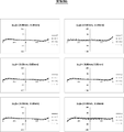
- FIG. 1 It is a lateral aberration diagram at the wide-angle end of the variable magnification optical system of Example 1.
- FIG. 2 It is a lateral aberration diagram at the telephoto end of the variable magnification optical system of Example 1.
- FIG. It is sectional drawing which shows the structure and the luminous flux at the wide-angle end of the variable magnification optical system of Example 2.
- FIG. 1 It is a partial cross-sectional view which shows the structure of the example which arranged the aperture diaphragm between the 3rd group and the 4th group, and the luminous flux.
- FIG. 1 It is sectional drawing which shows the structure and the luminous flux at the wide-angle end of the variable magnification optical system of Example 3.
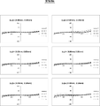
- FIG. 2 is a lateral aberration diagram at the wide-angle end of the variable magnification optical system of Example 3.
- FIG. 2 It is a lateral aberration diagram at the telephoto end of the variable magnification optical system of Example 3.
- FIG. 2 is sectional drawing which shows the structure and the luminous flux at the wide-angle end of the variable magnification optical system of Example 4.
- FIG. It is sectional drawing which shows the structure and the luminous flux at the wide-angle end of the variable magnification optical system of Example 5.
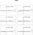
- FIG. It is a lateral aberration diagram at the wide-angle end of the variable magnification optical system of Example 5.
- FIG. It is a lateral aberration diagram at the telephoto end of the variable magnification optical system of Example 5.
- FIG. It is sectional drawing which shows the structure and the luminous flux at the wide-angle end of the variable magnification optical system of Example 6.
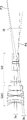
- FIG. 1 shows a cross-sectional view of a configuration at a wide-angle end of a variable magnification optical system according to an embodiment of the present disclosure.
- FIG. 2 shows a cross-sectional view of the configuration and the luminous flux in each variable magnification state of this variable magnification optical system.
- the upper row labeled "Wide” shows the wide-angle end state
- the middle row labeled "Middle” shows the intermediate focal length state
- the lower row labeled "Tele” shows the telephoto end state.
- the reference numerals are given only to the upper figure.
- FIGS. 1 and 2 show a state in which the object is in focus at infinity.
- the examples shown in FIGS. 1 and 2 correspond to the variable magnification optical system of the first embodiment described later.
- This variable magnification optical system can be applied to, for example, a surveillance camera.
- the variable magnification optical system of FIG. 1 forms a bending optical path, and the upper left side of FIG. 1 is the object side and the lower right side of FIG. 1 is the image side.
- This variable magnification optical system includes a first group G1 having two mirrors and a plurality of variable magnification groups arranged in an optical path on the image side of the first group G1.
- the variable magnification group is a group that moves by changing the distance from the adjacent group at the time of scaling. The scaling is performed by moving these scaling groups.
- the first group G1, the second group G2, and the third group are continuously continuous from the object side to the image side along the optical path and have power. It is a zoom optical system including G3, a fourth group G4, and a fifth group G5.
- the third group G3 and the fourth group G4 are scaling groups, and when scaling from the wide-angle end to the telephoto end, the third group G3 moves to the image side and the fourth group G4 is an object. Move to the side.
- the movement locus of each group when scaling from the wide-angle end to the telephoto end is schematically shown by arrows under the third group G3 and the fourth group G4, respectively.
- each group in the example of FIG. 1 is configured as follows.
- the first group G1 includes a first mirror M1, a lens L11, a lens L12, and a second mirror M2.
- the second group G2 is composed of a second A subgroup G2A, a second B subgroup G2B, and a second C subgroup G2C in order from the object side to the image side.
- the second A subgroup G2A consists of two lenses, lenses La1 and La2, in this order from the object side to the image side.
- the second B subgroup G2B is composed of three lenses Lb1 to Lb3 in order from the object side to the image side.
- the second C subgroup G2C is composed of six lenses Lc1 to Lc6 in order from the object side to the image side.
- the third group G3 is composed of four lenses L31 to L34 in order from the object side to the image side.
- the fourth group G4 is composed of five lenses L41 to L45 in order from the object side to the image side.
- the fifth group G5 is composed of nine lenses L51 to L59 in order from the object side to the image side.
- the aperture stop St is arranged between the third group G3 and the fourth group G4.
- the aperture stop St in FIG. 1 does not indicate the shape and size, but indicates the position in the traveling direction of light. This illustration method for the aperture stop St is the same in other figures.
- FIG. 1 shows an example in which a parallel plate-shaped optical member PP is arranged between the variable magnification optical system and the image plane Sim on the assumption that the variable magnification optical system is applied to an image pickup apparatus.
- the optical member PP is a member that assumes various filters, a cover glass, and the like.
- the various filters are, for example, a low-pass filter, an infrared cut filter, and a filter that cuts a specific wavelength range.
- the optical member PP is a member having no power. It is also possible to configure the image pickup apparatus by omitting the optical member PP.
- the light incident on the variable magnification optical system from the object is first reflected to the object side by the first mirror M1, passes through the lens L11 and the lens L12 in this order, and then passes through the image side by the second mirror M2.
- the image plane Sim is reached via the second group G2, the third group G3, the fourth group G4, the fifth group G5, and the optical member PP. ..
- a ray passing through the apex of the optical surface of the variable magnification group will be referred to as a reference ray 2 and will be described.
- the optical plane constituting the scaling group includes a plane
- the plane is not included in the plane defining the reference ray 2.
- the optical surface of the lens is the lens surface.
- the reference ray 2 passes through the surface vertices of all the lens surfaces of the variable magnification group.
- the apex of the optical surface is conveniently set to the bottom point in the optical surface, that is, the apex when the air side is viewed from the optical element side.
- the reference ray 2 will be determined as.
- the direction of the reference ray 2 incident on the first group G1 from the object side is defined as the Z-axis direction.
- the surface including both the reference ray 2 incident on the first group G1 from the object side and the reference ray 2 passing between the two mirrors of the first group G1 is defined as a YZ surface. That is, the paper surface of FIG. 1 is the YZ surface.
- the left-right direction is the Z-axis direction
- the up-down direction is the Y-axis direction
- the direction perpendicular to the paper surface is the X-axis direction.
- the positive direction in the Z-axis direction is from left to right
- the positive direction in the Y-axis direction is from bottom to top
- the positive direction in the X-axis direction is from the back side to the front side of the paper.
- the first group G1 includes a first mirror M1 having a concave reflecting surface facing the object side.
- the first group G1 includes, in addition to the first mirror M1 having the above configuration, a second mirror M2 that reflects light from the first mirror M1 toward the object side toward the image side.
- the second mirror M2 has a convex reflecting surface facing the image side. According to the two mirrors having the above configuration, the light flux deflected to the object side by the reflection by the first mirror M1 is reflected by the second mirror M2 having a convex shape and deflected to the image side again, and the optical path is folded back. be able to. Therefore, it is possible to suppress an increase in the total length of the optical system in the Z direction due to telephoto by folding back the optical path while adopting a telephoto type configuration by combining the first mirror M1 and the second mirror M2. Further, since the mirror does not participate in chromatic aberration, using the above two mirrors is advantageous for chromatic aberration, which tends to be a problem in an optical system having a long focal length.
- the point where the reflection surface of the first mirror M1 and the reference ray 2 intersect is defined as the intersection point P1.
- the normal of the reflecting surface of the first mirror M1 at the intersection P1 is shown by a broken line.
- the angle formed by this normal and the reference ray 2 is defined as Ang0.
- the variable magnification optical system of this embodiment is configured so that the absolute value of Ang0 is 2 degrees or more.
- the first mirror M1 and the second mirror M2 are arranged on non-coaxial axes with each other. These points are significantly different from the optical system described in JP-A-2019-148790.
- the optical system of this comparative example includes a first mirror M1 and a second mirror M2 in which the reflecting surfaces of each other are arranged to face each other.
- the first mirror M1 and the second mirror M2 of the comparative example have a common optical axis, and the second mirror M2 is arranged in the optical path of the first mirror M1. Therefore, the first mirror M1 is configured in a ring shape having an aperture, and the central portion of the incident light flux to the variable magnification optical system is shielded by the second mirror M2, resulting in light loss.
- the comparative example has the following problems with wide angle of view.
- the wider the angle of view the smaller the incident luminous flux diameter, that is, the entrance pupil diameter. Therefore, in the comparative example in which the central portion of the incident light flux is shaded by the second mirror M2, the ratio of the light flux shaded by the second mirror M2 to the diameter of the incident light beam becomes large when the wide angle of view is promoted. It ends up. Due to such circumstances, it is difficult to widen the angle of view while ensuring the desired illuminance in the comparative example.
- variable magnification optical system of the present embodiment shown in FIG. 1 since the absolute value of Ang0 is configured to be 2 degrees or more, the light beam incident on the first mirror M1 from the object side is the first. After being reflected by the mirror M1, it can be ejected in a direction deviating from the incident optical path. As a result, as shown in FIG. 2, the second mirror M2 located on the object side of the first mirror M1 can be arranged at a position where the incident light flux to the variable magnification optical system is not shielded from light, unlike the comparative example. It becomes.
- the second mirror M2 can be configured not to block the incident light flux, which is advantageous for wide-angle. Further, even on the telephoto side where the incident luminous flux diameter is large, the central portion of the incident luminous flux is not shielded from light, so that the light amount loss as in the comparative example does not occur. Therefore, when compared with the same incident luminous flux diameter, the configuration of the present embodiment can capture more light than the comparative example.
- variable magnification optical system of the present embodiment all the light from the object, which is reflected by the first mirror M1 and then reflected by the second mirror M2, is the first mirror M1. It passes radially outside from the outer edge of.
- the radial direction referred to here means the radial direction of the reflecting surface of the first mirror M1 centered on the intersection P1.
- the first mirror M1 is provided with an opening for passing a light flux in the central portion.
- the first mirror M1 of the present embodiment does not need to be provided with an opening for passing a light beam, and therefore, when compared with the same incident light flux diameter, a larger amount of light is obtained than in the comparative example. be able to.
- the angle formed by the reference ray 2 incident on the first mirror M1 and the reference ray 2 emitted from the first mirror M1 is Ang1
- the light flux incident on the first mirror M1 By not exceeding the upper limit of the conditional expression (1), the occurrence of coma aberration due to the normal of the reflecting surface of the first mirror M1 at the intersection P1 being tilted with respect to the reference ray 2 is suppressed. be able to.
- variable magnification optical system preferably satisfies the following conditional expression (1-1), and even more preferably the following conditional expression (1-2). 4 ⁇
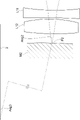
- FIG. 3 shows a partially enlarged view of the area around the intersection P2 and Ang2.
- variable magnification optical system satisfies the following conditional expression (2-1), and it is even more preferable that the following conditional expression (2-2) is satisfied. 5 ⁇
- FIG. 3 shows Ang3.
- the extension line on the second mirror side of the reference ray 2 emitted from the second mirror M2 is shown by a two-dot chain line.
- the reference ray 2 incident on the first mirror M1 is shown by a solid line above the second mirror M2.
- FIG. 3 is a schematic diagram for showing an angle, and the distance between the second mirror M2 and the reference ray 2 incident on the first mirror M1 in FIG. 3 is not accurate.
- the variable magnification optical system preferably satisfies the following conditional expression (3-1), and even more preferably the following conditional expression (3-2). 4 ⁇
- the first mirror M1 may be an optical element located closest to the object on the optical path among the optical elements having power included in the variable magnification optical system. In this way, the concerns described below can be avoided. If the refractive optics system is arranged in the optical path on the object side of the first mirror M1, the refractive optics system has a large aperture. In that case, the center of gravity of the variable magnification optical system may be biased toward the tip portion, resulting in poor weight balance and high cost.
- the first mirror M1 and the second mirror M2 are configured to be fixed to the image plane Sim.
- the first mirror M1 is a large component because it has a size that covers the entrance pupil diameter on the telephoto side.
- a mechanism for moving the first mirror M1 becomes unnecessary, and it is possible to avoid an increase in the size of the device.
- the mechanical structure around the second mirror M2 can be simplified. As a result, it becomes easy to prevent the mechanical parts around the second mirror M2 from blocking the light beam for image formation, which is advantageous in suppressing the light amount loss.
- the first group G1 is fixed to the image plane Sim. That is, it is preferable that all the optical elements constituting the first group G1 including the elements other than the mirror are fixed to the image plane Sim at the time of scaling. In this case, it is advantageous to simplify the configuration of the device.
- the first group G1 is configured to form an intermediate image Im inside the variable magnification optical system.
- the intermediate image Im is reimaged on the image plane Sim via the group on the image side of the intermediate image Im on the optical path.
- the variable magnification optical system As the re-imaging optical system, it is advantageous to reduce the diameter of each group.
- an intermediate image Im is formed in the optical path between the first group G1 and the second group G2. In FIGS. 1 and 2, only a part of the intermediate image Im is simply represented by a dotted line.
- Two or more scaling groups are arranged on the optical path on the image side of the intermediate image Im.
- a mechanical structure for moving the variable magnification group without blocking the light flux folded back by the first mirror M1 and the second mirror M2 is arranged. Becomes easier.
- the first group G1 may be configured to include the correction lens group Gh.
- the correction lens group Gh is preferably arranged in the first group G1 so as to be located on the optical path from the first mirror M1 to the second mirror M2 and on the optical path from the second mirror M2 to the intermediate image Im. .. In this case, the light beam passes through the correction lens group Gh twice.
- the correction lens group Gh is preferably composed of only one or more refracting lenses. If a mirror is used instead of the correction lens group Gh to perform the same correction, a folded optical path is further formed, which may cause light shielding due to interference between the luminous flux and the member. Alternatively, there is a risk that the optical system will become large in size in order to arrange the members so that this shading does not occur.
- a "refractive lens” is also simply referred to as a "lens”.
- the correction lens group Gh in FIG. 1 includes a lens L11 which is a negative lens and a lens L12 which is a positive lens.
- the lens L11 and the lens L12 in the example of FIG. 1 are spherical lenses.
- the first group G1 includes the correction lens group Gh
- at least one reflecting surface of the first mirror M1 and the second mirror M2 has a spherical shape.
- the correction lens group Gh arranged at the above position and the spherical mirror are combined, the coma aberration generated when the absolute value of Ang0 becomes 2 degrees or more, and the spherical surface generated by the spherical mirror. It becomes easy to correct the aberration. Further, according to the above-mentioned combination configuration, it becomes easy to construct a variable magnification optical system capable of achieving the object of the present invention without using an expensive aspherical mirror.
- the focal length of the first mirror M1 is f1 and the distance from the intersection P1 to the intersection P2 is DL12
- the following conditional expression (4) can be satisfied.
- the intersection P1 and the intersection P2 are the intersections defined above, respectively.
- variable magnification optical system preferably satisfies the following conditional expression (4-1), and even more preferably the following conditional expression (4-2). 0.4 ⁇ DL12 /
- the variable magnification optical system of FIG. 1 includes a first group G1 and a second group G2 arranged on the image side from the intermediate image Im in order from the object side to the image side along the optical path.
- the second group G2 may be configured such that adjacent subgroups are composed of a plurality of subgroups arranged on non-coaxial axes with each other. Since the first mirror M1 and the second mirror M2 are arranged on non-coaxial axes with each other, coma aberration due to eccentricity occurs. By arranging a plurality of subgroups in the second group G2 on non-coaxial axes, it is advantageous to correct the coma aberration associated with this eccentricity.
- the second group G2 includes a second A subgroup G2A having a positive power and a second B subgroup G2B having a negative power in order from the object side to the image side along the optical path.
- the second A subgroup G2A and the second B subgroup G2B may be configured to be arranged non-coaxial with each other. According to this configuration, it is advantageous to correct the coma aberration associated with the above eccentricity. Further, by arranging the second A subgroup G2A having a positive power at the position where the light flux diverges on the image side of the intermediate image Im, the divergence of the light flux can be suppressed. This is advantageous for reducing the diameter of the group on the image side of the second A subgroup G2A. By arranging the second B subgroup G2B having a power opposite to that of the second A subgroup G2A continuously to the second A subgroup G2A, it is advantageous for aberration correction.
- the second group G2 has a second A subgroup G2A having a positive power, a second B subgroup G2B having a negative power, and a positive one in order from the object side to the image side along the optical path. It may be configured to consist of a second C subgroup G2C having power.
- the second A subgroup G2A and the second B subgroup G2B are arranged so as to be non-coaxial with each other, and the second B subgroup G2B and the second C subgroup G2C are arranged so as to be non-coaxial with each other. May be good. According to this configuration, it is advantageous to correct the coma aberration associated with the above eccentricity.
- the powers of the adjacent subgroups so as to have opposite signs to each other, it is advantageous for aberration correction.
- the second C subgroup G2C having a positive power on the most image side of the second group G2 it is possible to give a converging action to the divergent light flux from the intermediate image Im toward the image side. It is more advantageous to reduce the diameter of the image side group than the 2 group G2.
- the secondA subgroup G2A and the secondC subgroup G2C may be arranged non-coaxially with each other or may be co-axised with each other. good. Further, the second A subgroup G2A and the variable magnification group may be arranged on the non-coaxial axis with each other, or may be arranged on the co-axis with each other. The second B subgroup G2B and the variable magnification group may be arranged non-coaxial with each other. The second C subgroup G2C and the variable magnification group may be arranged on the same axis with each other.
- the second A subgroup G2A may be configured to be a refractive optics system.
- the second B subgroup G2B may be configured to be a refractive optics system.
- the second C subgroup G2C may be configured to be a refractive optics system.
- the "refractive optical system" in the present specification is an optical system that does not include a reflecting optical element having power and includes only a refracting lens as an optical element having power. When a reflective optical element is used, the optical path is folded back, so that there is a possibility that a problem of light shielding due to interference between the light flux and the member may occur. Alternatively, there is a risk that the optical system will become large in size in order to arrange the members so that this shading does not occur. By using a refractive optics system, it is possible to avoid this problem.
- the second A subgroup G2A having a positive power and the second B subgroup G2B having a negative power are included.
- the focal distance of the 2A subgroup G2A is fG2A and the focal distance of the second B subgroup G2B is fG2B, it is preferable that the following conditional expression (5) is satisfied.
- the group is continuously arranged in the second B subgroup G2B on the image side of the second B subgroup G2B (in the example of FIG. 1, the second C subgroup). It is possible to prevent the outer diameter of G2C) from becoming large.
- the positive power of the second A subgroup G2A does not become too strong, so that the occurrence of spherical aberration on the telephoto side can be suppressed.
- the negative power of the second B subgroup G2B does not become too weak, it is advantageous to correct the coma aberration due to the eccentricity.
- variable magnification optical system satisfies the following conditional expression (5-1), and it is even more preferable that the following conditional expression (5-2) is satisfied.
- conditional expression (5-2) -1 ⁇ fG2A / fG2B ⁇ -0.01 (5) -0.75 ⁇ fG2A / fG2B ⁇ -0.02 (5-1) -0.5 ⁇ fG2A / fG2B ⁇ -0.04 (5-2)
- the second group G2 is fixed to the image plane Sim.
- a mechanism for moving the second group G2 becomes unnecessary, and it is possible to suppress an increase in the size of the device.
- the mechanical structure around the second group G2 can be simplified. This is advantageous in preventing the light flux from the first mirror M1 to the second mirror M2 from being shielded by the mechanical parts around the second group G2.
- variable magnification optical system consists of the first group G1 as a group having power in order from the object side to the image side along the optical path, the second group G2 arranged on the image side from the intermediate image Im, and the third group G3. And only the 4th group G4 and the succeeding group.
- the second group G2 consists of a plurality of subgroups in which adjacent subgroups are arranged on non-coaxial axes with each other, and is the most image-side subgroup of the second group G2 on the optical path (the second C subgroup in the example of FIG. 1).
- G2C has a positive power.
- the third group G3 is a refraction optical system having a negative power
- the fourth group G4 is a refraction optical system having a positive power.
- the second group G2 is fixed to the image plane Sim, and the third group G3 and the fourth group G4 move in opposite directions to each other.
- the most image-side subgroup of the second group G2, the third group G3, and the fourth group G4 have positive, negative, and positive powers, respectively. In this way, by arranging the powers of the adjacent subgroups so as to have opposite signs to each other, it is possible to give each group a strong power.
- the amount of movement of the third group G3 and the fourth group G4 at the time of scaling can be suppressed, which is advantageous for miniaturization of the optical system. Further, by converging the luminous flux diverged by the negative power third group G3 with the positive power fourth group G4 on the image side, it is possible to suppress the increase in the outer diameter of the subsequent group. ..
- the variable magnification optical system includes the above-mentioned third group G3 and fourth group G4, when the focal length of the third group G3 is fG3 and the focal length of the fourth group G4 is fG4, the following conditional expression (6) It is preferable to satisfy. By making sure that the power does not fall below the lower limit of the conditional expression (6), the power of the fourth group G4 does not become too weak, so that the amount of movement of the fourth group G4 at the time of scaling can be suppressed. This makes it possible to suppress an increase in the size of the optical system mainly in the Z-axis direction.
- the power of the third group G3 does not become too strong, the spherical aberration generated in the third group G3 can be suppressed.
- the power of the third group G3 does not become too weak, so that the movement amount of the fourth group G4 at the time of scaling can be suppressed. This makes it possible to suppress an increase in the size of the optical system mainly in the Z-axis direction. Further, since the power of the fourth group G4 does not become too strong, the spherical aberration generated in the fourth group G4 can be suppressed.
- variable magnification optical system satisfies the following conditional expression (6-1), and it is even more preferable that the following conditional expression (6-2) is satisfied.
- 6-1 the following conditional expression
- 6-2 the following conditional expression (6-2) is satisfied.
- the subsequent group consists of the 5th group G5 in the example of FIG.
- the subsequent group is not limited to the composition consisting of one group.
- Subsequent groups may be configured to consist of two groups, or three or more groups, whose mutual spacing changes upon scaling.
- the succeeding group consists of a plurality of groups
- the group on the most image side of the succeeding group may be configured to be fixed at the time of scaling. In this case, it is advantageous to simplify the device configuration.
- the aperture stop St is fixed to the image plane Sim at the time of scaling. It is preferable that the aperture diameter of the aperture stop St is variable in order to cope with various imaging conditions. In particular, it is preferable that the aperture diameter is variable in surveillance camera applications where shooting is performed day and night.
- the aperture throttle St is fixed at the time of scaling, the arrangement of the diaphragm mechanism for changing the aperture diameter becomes easy.
- the aperture throttle St is configured to move at the time of scaling, a conductor for supplying electric power to the driving component for driving the aperture throttle St is required, and there is a risk that the conductor will be disconnected. Occurs.
- the aperture stop St is fixed at the time of scaling, such a risk does not occur, so that the durability, which is important for monitoring applications, can be maintained higher.
- the aperture stop St may be configured to be arranged on the image side of the most image side surface of the variable magnification group on the most object side on the optical path.
- the arrangement of the diaphragm mechanism becomes easy, and it is advantageous for the miniaturization of the diaphragm mechanism.
- the most image-side surface of the variable magnification group on the most object side is the object-side surface of the lens L34 of the third group G3.
- the aperture stop St is configured to be arranged between the most object-side surface of the most object-side scaling group and the most image-side surface of the most image-side scaling group on the optical path.
- the surface on the object side of the variable magnification group on the most object side is the surface on the object side of the lens L31 of the third group G3, and the surface on the image side of the variable magnification group on the image side is the surface on the image side.
- the aperture stop St is arranged at the air spacing between the third group G3 and the fourth group G4.
- the aperture stop St is preferably arranged at a position where a part of the image forming region is not shielded from light when the aperture stop St is stopped down. Therefore, the position of the aperture stop St is from the point where the upper ray of the on-axis luminous flux and the upper ray of the off-axis luminous flux intersect (hereinafter referred to as point P3) to the lower ray of the on-axis luminous flux and the lower ray of the off-axis luminous flux. It is preferably within the range up to the point where and (hereinafter referred to as point P4) intersect.
- the luminous flux whose main ray is the reference ray 2 is referred to as an on-axis luminous flux
- the luminous flux whose main ray is not the reference ray 2 is referred to as an off-axis luminous flux.
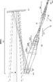
- FIG. 4A shows an example in which the aperture stop St is arranged between the second group G2C and the third group G3.
- FIG. 4A also shows an on-axis luminous flux 3a, an off-axis luminous flux 3b, the above points P3, and points P4.
- the opening throttle St is arranged between the 2nd C subgroup G2C and the 3rd group G3, the range from the point P3 to the point P4 is in the vicinity of the 3rd group G3 as shown in FIG.
- the distance between the second C subgroup G2C and the opening diaphragm St becomes wider at the wide angle end. Therefore, the distance between the second C subgroup G2C and the third group G3 also becomes wide, which leads to an increase in the total optical length.
- FIG. 4B shows an example in which the aperture stop St is arranged between the third group G3 and the fourth group G4.
- the off-axis luminous flux 3b ejected from the second C subgroup G2C and incident on the third group G3 is diverged by the negative power third group G3. Therefore, the tilt angle of the off-axis luminous flux 3b emitted from the third group G3 with respect to the optical axis Z is smaller than the tilt angle of the off-axis luminous flux 3b emitted from the second C subgroup G2C with respect to the optical axis Z. Therefore, the points P3 and P4 are located closer to the image side than in the case where the aperture stop St is arranged between the second C subgroup G2C and the third group G3.
- the aperture stop St By arranging the aperture stop St on the object side of the most image-side variable magnification group on the object side, it is advantageous to suppress the enlargement in the radial direction. If the aperture stop St is arranged on the image side of the most image-side surface of the variable magnification group on the image-side side, more light rays under the off-axis luminous flux must pass through, so that the third There is a risk that the outer diameter of group G3 will increase.
- variable magnification optical system of the present disclosure can be variously modified within a range that does not deviate from the gist of the technique of the present disclosure.
- the number of optical elements included in each group and the number of variable magnification groups can be arbitrarily selected.
- Each group is not limited to the configuration consisting of a plurality of optical elements, and may be configured to be composed of one optical element.
- the example of FIG. 1 is a zoom optical system
- the variable magnification optical system of the present disclosure may be a varifocal optical system.
- the above-mentioned preferable configuration and possible configuration can be any combination, and it is preferable that they are appropriately and selectively adopted according to the required specifications.
- variable magnification optical system of the present disclosure The cross-sectional views of the variable magnification optical system of the first embodiment are shown in FIGS. 1 and 2, and the configuration and the method of illustration thereof are as described above.
- the first group G1, the second group G2, the third group G3, the opening aperture St, and the fourth group are sequentially arranged from the object side to the image side along the optical path.
- It is a zoom optical system including G4 and the fifth group G5.
- An intermediate image Im is formed in the optical path between the first group G1 and the second group G2.
- the first group G1 includes a first mirror M1, a second mirror M2, and a correction lens group Gh.
- the correction lens group Gh includes a lens L11 and a lens L12.
- the second group G2 is composed of a second A subgroup G2A, a second B subgroup G2B, and a second C subgroup G2C in order from the object side to the image side.
- the second A subgroup G2A consists of two lenses, lenses La1 and La2, in this order from the object side to the image side.
- the second B subgroup G2B is composed of three lenses Lb1 to Lb3 in order from the object side to the image side.
- the second C subgroup G2C is composed of six lenses Lc1 to Lc6 in order from the object side to the image side.
- the second A subgroup G2A, the second B subgroup G2B, and the second C subgroup G2C are arranged non-coaxially with each other.
- the second group G2C, the third group G3, the aperture stop St, the fourth group G4, and the fifth group G5 are arranged on the same axis with each other.
- the third group G3 is composed of four lenses L31 to L34 in order from the object side to the image side.
- the fourth group G4 is composed of five lenses L41 to L45 in order from the object side to the image side.
- the fifth group G5 is composed of nine lenses L51 to L59 in order from the object side to the image side.
- the basic lens data is shown in Tables 1A and 1B, the coordinate data of the variable magnification group is shown in Table 2, and the specifications are shown in Table 3.
- the basic lens data is divided into two tables, Table 1A and Table 1B, in order to avoid lengthening one table.
- Table 1A shows the first group G1 and the second group G2
- Table 1B shows the third group G3, the aperture stop St, the fourth group G4, the fifth group G5, and the optical member PP.
- each table the values in the XYZ coordinate system using the above-mentioned X-axis, Y-axis, and Z-axis are shown with the point O shown in FIG. 1 as the origin.
- Tables 1A and 1B show the components along the optical path.
- each column will be described.
- the plane number including the point O and perpendicular to the Z axis is set as the first plane, and the plane number is shown when the number is increased one by one toward the image side along the optical path.
- the symbol "(St)" is also entered in the "surface number” column of the surface corresponding to the aperture stop St.
- the radius of curvature of each surface is shown in the column of "radius of curvature".
- the sign of the radius of curvature the sign of the surface having the convex surface facing the object side is positive, and the sign of the surface having the convex surface facing the image side is negative.
- the coordinates in the XYZ coordinate system of the center of curvature of each surface are shown with respect to the point O, respectively.
- Table 2 shows the coordinates of each surface of the 3rd group G3 and the 4th group G4 for each zoom position.
- Tables 2 and 3 the values at each zoom position in the wide-angle end state, the intermediate focal length state, and the telephoto end state are shown in the columns described as "Wide”, “Middle”, and "Tele”, respectively.
- the column of "on-axis luminous flux diameter" indicates the diameter of the on-axis luminous flux incident on the variable magnification optical system.
- the main rays having the maximum angle of view incident on the upper side and the lower side of the reference ray 2 will be referred to as an upper main ray and a lower main ray, respectively.
- ⁇ 1 is the incident angle of the upper main ray, that is, the angle formed by the upper main ray and the reference ray 2.
- ⁇ 2 is the incident angle of the lower main ray, that is, the angle formed by the lower main ray and the reference ray 2.
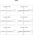
- FIG. 5 shows a lateral aberration diagram at the wide-angle end of the variable magnification optical system of Example 1.
- the left column shows the aberration in the sagittal direction
- the right column shows the aberration in the tangential direction.
- Aberrations on the d-line, F-line, C-line, and s-line are shown by solid lines, long dashed lines, alternate long and short dash lines, and dotted lines, respectively.
- the unit of the vertical axis is ⁇ m (micrometer).
- the coordinates are represented using an xyz coordinate system different from the above-mentioned XYZ coordinate system.
- the intersection of the reference ray 2 and the image plane Sim is set as the origin, and the x-axis, y-axis, and z-axis that are orthogonal to each other are used as described below.
- the direction of the reference ray 2 incident on the image plane Sim from the variable magnification optical system is defined as the z-axis direction
- the paper surface of FIG. 1 is defined as the yz plane
- the direction perpendicular to the paper surface is defined as the x-axis direction.
- the positive direction in the z-axis direction is the direction from the variable magnification optical system toward the image plane Sim
- the positive direction in the y-axis direction is the direction in which the first mirror M1 is located with respect to the reference ray 2 incident on the image plane Sim, the x-axis.
- the positive direction is from the back side of the paper to the front side.
- FIG. 6 shows a lateral aberration diagram at the telephoto end of the variable magnification optical system of Example 1. Also in FIG. 6, the aberration in the sagittal direction is shown in the left column, and the aberration in the tangential direction is shown in the right column.
- the illustration method of FIG. 6 is basically the same as that of FIG. 5 and 6 show aberrations in the state of being in focus on an infinity object.
- FIG. 7 shows a cross-sectional view and a luminous flux at the wide-angle end of the variable magnification optical system of Example 2.
- the first group G1, the second group G2, the third group G3, the opening aperture St, and the fourth group are sequentially arranged from the object side to the image side along the optical path.
- It is a zoom optical system including G4 and the fifth group G5.
- An intermediate image Im is formed in the optical path between the first group G1 and the second group G2.
- the first group G1 includes a first mirror M1, a second mirror M2, and a correction lens group Gh.
- the correction lens group Gh consists of two lenses.
- the second group G2 is composed of a second A subgroup G2A, a second B subgroup G2B, and a second C subgroup G2C in order from the object side to the image side.
- the second A subgroup G2A consists of two lenses.
- the second B subgroup G2B consists of three lenses.
- the second C subgroup G2C consists of six lenses.
- the second A subgroup G2A, the second B subgroup G2B, and the second C subgroup G2C are arranged non-coaxially with each other.
- the second group G2C, the third group G3, the aperture stop St, the fourth group G4, and the fifth group G5 are arranged on the same axis with each other.
- the third group G3 consists of four lenses.
- the fourth group G4 consists of five lenses.
- the fifth group G5 consists of nine lenses. The above is the outline of the variable magnification optical system of the second embodiment.
- variable magnification optical system of Example 2 the basic lens data is shown in Tables 4A and 4B, the coordinate data of the variable magnification group is shown in Table 5, the specifications are shown in Table 6, and the lateral aberration diagram at the wide-angle end is shown in FIG. The lateral aberration diagram at the telephoto end is shown in FIG.
- FIG. 10 shows a cross-sectional view and a luminous flux at the wide-angle end of the variable magnification optical system of Example 3.
- the variable magnification optical system of Example 3 has the same configuration as the outline of the variable magnification optical system of Example 2.
- the basic lens data is shown in Tables 7A and 7B
- the coordinate data of the variable magnification group is shown in Table 8
- the specifications are shown in Table 9
- the lateral aberration diagram at the wide-angle end is shown in FIG.
- the lateral aberration diagram at the telephoto end is shown in FIG.
- FIG. 13 shows a cross-sectional view and a luminous flux at the wide-angle end of the variable magnification optical system of Example 4.
- the variable magnification optical system of Example 4 has the same configuration as the outline of the variable magnification optical system of Example 2.
- the basic lens data is shown in Tables 10A and 10B
- the coordinate data of the variable magnification group is shown in Table 11
- the specifications are shown in Table 12
- the lateral aberration diagram at the wide-angle end is shown in FIG.
- the lateral aberration diagram at the telephoto end is shown in FIG.
- FIG. 16 shows a cross-sectional view and a luminous flux at the wide-angle end of the variable magnification optical system of Example 5.
- the variable magnification optical system of Example 5 has the same configuration as the outline of the variable magnification optical system of Example 2.
- the basic lens data is shown in Tables 13A and 13B
- the coordinate data of the variable magnification group is shown in Table 14
- the specifications are shown in Table 15,
- the lateral aberration diagram at the wide-angle end is shown in FIG.
- the lateral aberration diagram at the telephoto end is shown in FIG.
- FIG. 19 shows a cross-sectional view and a luminous flux at the wide-angle end of the variable magnification optical system of Example 6.
- the first group G1, the second group G2, the third group G3, the opening aperture St, and the fourth group are sequentially arranged from the object side to the image side along the optical path.
- It is a zoom optical system including G4, a fifth group G5, and a sixth group G6.
- An intermediate image Im is formed in the optical path between the first group G1 and the second group G2.
- the first group G1 includes a first mirror M1, a second mirror M2, and a correction lens group Gh.
- the correction lens group Gh consists of two lenses.
- the second group G2 is composed of a second A subgroup G2A, a second B subgroup G2B, and a second C subgroup G2C in order from the object side to the image side.
- the second A subgroup G2A consists of two lenses.
- the second B subgroup G2B consists of three lenses.
- the second C subgroup G2C consists of six lenses.
- the second A subgroup G2A, the second B subgroup G2B, and the second C subgroup G2C are arranged non-coaxially with each other.
- the second group G2C, the third group G3, the aperture stop St, the fourth group G4, the fifth group G5, and the sixth group G6 are arranged on the same axis with each other.
- the third group G3 consists of four lenses.
- the fourth group G4 consists of five lenses.
- the fifth group G5 consists of six lenses.
- the sixth group G6 consists of three lenses.
- variable magnification optical system of Example 6 the basic lens data is shown in Tables 16A and 16B, the coordinate data of the variable magnification group is shown in Tables 17A and 17B, the specifications are shown in Table 18, and the lateral aberration diagram at the wide-angle end is shown. 20 shows a lateral aberration diagram at the telephoto end in FIG. 21.
- Table 19 shows the corresponding values of
- the values shown in Table 19 are values based on the d-line.
- variable magnification optical systems of Examples 1 to 6 have a magnification ratio of 6.5 times or more, and in particular, the variable magnification optical systems of Examples 2 to 6 have a magnification ratio of 10 times or more.
- the variable magnification optical systems of Examples 1 to 6 achieve a wide angle of view while achieving such a high magnification ratio while suppressing light loss, are compactly configured, and are close to the visible light region. It has high optical performance with good correction of various aberrations in a wide range up to the infrared light region. Further, the variable magnification optical systems of Examples 1 to 6 are designed to reduce the load on the portion on the object side, and realize a telephoto system of reflection / refraction type variable magnification optical system while having an inexpensive configuration.
- FIG. 22 shows a schematic configuration diagram of an image pickup apparatus 10 using the variable magnification optical system 1 according to the embodiment of the present disclosure as an example of the image pickup apparatus according to the embodiment of the present disclosure.
- Examples of the image pickup apparatus 10 include a surveillance camera, a video camera, an electronic still camera, and the like.
- the image pickup apparatus 10 receives output signals from the variable magnification optical system 1, the filter 4 arranged on the image side of the variable magnification optical system 1, the image pickup element 5 arranged on the image side of the filter 4, and the image pickup element 5. It includes a signal processing unit 6 for arithmetic processing and a scaling control unit 7 for controlling the scaling of the scaling optical system 1.
- the image sensor 5 converts the optical image formed by the variable magnification optical system 1 into an electric signal.
- the image pickup device 5 for example, a CCD (Charge Coupled Device) or a CMOS (Complementary Metal Oxide Semiconductor) or the like can be used.
- the image pickup device 5 is arranged so that its image pickup surface coincides with the image plane of the variable magnification optical system 1.
- the image pickup device 10 may be configured to include a plurality of image pickup elements.
- the techniques of the present disclosure have been described above with reference to embodiments and examples, the techniques of the present disclosure are not limited to the above embodiments and examples, and various modifications are possible.
- the radius of curvature, the coordinates, the refractive index, the Abbe number, and the like of each optical element are not limited to the values shown in the above numerical examples, and may take other values.
Landscapes
- Physics & Mathematics (AREA)
- General Physics & Mathematics (AREA)
- Optics & Photonics (AREA)
- Lenses (AREA)
Priority Applications (1)
| Application Number | Priority Date | Filing Date | Title |
|---|---|---|---|
| JP2022572050A JP7317252B2 (ja) | 2020-12-21 | 2021-12-02 | 変倍光学系および撮像装置 |
Applications Claiming Priority (2)
| Application Number | Priority Date | Filing Date | Title |
|---|---|---|---|
| JP2020211714 | 2020-12-21 | ||
| JP2020-211714 | 2020-12-21 |
Publications (1)
| Publication Number | Publication Date |
|---|---|
| WO2022138054A1 true WO2022138054A1 (ja) | 2022-06-30 |
Family
ID=82159505
Family Applications (1)
| Application Number | Title | Priority Date | Filing Date |
|---|---|---|---|
| PCT/JP2021/044335 Ceased WO2022138054A1 (ja) | 2020-12-21 | 2021-12-02 | 変倍光学系および撮像装置 |
Country Status (2)
| Country | Link |
|---|---|
| JP (1) | JP7317252B2 (https=) |
| WO (1) | WO2022138054A1 (https=) |
Citations (6)
| Publication number | Priority date | Publication date | Assignee | Title |
|---|---|---|---|---|
| US4971428A (en) * | 1989-03-27 | 1990-11-20 | Lenzar Optics Corporation | Catadioptric zoom lens |
| JPH11202208A (ja) * | 1997-10-27 | 1999-07-30 | Wescam Inc | 反射屈折光学系ズームレンズ組立体 |
| CN106772963A (zh) * | 2017-01-26 | 2017-05-31 | 西安应用光学研究所 | 全球面大口径折反式连续变焦光学系统 |
| JP2019148790A (ja) * | 2018-02-27 | 2019-09-05 | 富士フイルム株式会社 | 変倍光学系及び撮像装置 |
| CN110515189A (zh) * | 2019-09-27 | 2019-11-29 | Oppo广东移动通信有限公司 | 离轴折反式摄像头和电子装置 |
| WO2021085142A1 (ja) * | 2019-10-29 | 2021-05-06 | 富士フイルム株式会社 | 変倍光学系および撮像装置 |
-
2021
- 2021-12-02 JP JP2022572050A patent/JP7317252B2/ja active Active
- 2021-12-02 WO PCT/JP2021/044335 patent/WO2022138054A1/ja not_active Ceased
Patent Citations (6)
| Publication number | Priority date | Publication date | Assignee | Title |
|---|---|---|---|---|
| US4971428A (en) * | 1989-03-27 | 1990-11-20 | Lenzar Optics Corporation | Catadioptric zoom lens |
| JPH11202208A (ja) * | 1997-10-27 | 1999-07-30 | Wescam Inc | 反射屈折光学系ズームレンズ組立体 |
| CN106772963A (zh) * | 2017-01-26 | 2017-05-31 | 西安应用光学研究所 | 全球面大口径折反式连续变焦光学系统 |
| JP2019148790A (ja) * | 2018-02-27 | 2019-09-05 | 富士フイルム株式会社 | 変倍光学系及び撮像装置 |
| CN110515189A (zh) * | 2019-09-27 | 2019-11-29 | Oppo广东移动通信有限公司 | 离轴折反式摄像头和电子装置 |
| WO2021085142A1 (ja) * | 2019-10-29 | 2021-05-06 | 富士フイルム株式会社 | 変倍光学系および撮像装置 |
Also Published As
| Publication number | Publication date |
|---|---|
| JPWO2022138054A1 (https=) | 2022-06-30 |
| JP7317252B2 (ja) | 2023-07-28 |
Similar Documents
| Publication | Publication Date | Title |
|---|---|---|
| JP5694508B2 (ja) | 変倍光学系および撮像装置 | |
| KR102385167B1 (ko) | 줌렌즈 및 이 줌렌즈를 갖는 촬상 장치 | |
| JP4317928B2 (ja) | ズームレンズ | |
| JP6685944B2 (ja) | ズームレンズおよび撮像装置 | |
| KR101707874B1 (ko) | 촬상 광학계 | |
| JP7109686B2 (ja) | 変倍光学系および撮像装置 | |
| JP2011107312A (ja) | ズームレンズ及びそれを有する撮像装置 | |
| JP2017026974A (ja) | 変倍光学系および撮像装置 | |
| JP2017161567A (ja) | ズームレンズ及びそれを有する撮像装置 | |
| JP6493896B2 (ja) | ズームレンズおよび撮像装置 | |
| JP6356639B2 (ja) | 変倍光学系および撮像装置 | |
| JP6649287B2 (ja) | ズームレンズおよび撮像装置 | |
| JP3723643B2 (ja) | 高変倍ズームレンズ系 | |
| JP2018194750A (ja) | ズームレンズおよび撮像装置 | |
| JP7314200B2 (ja) | 変倍光学系および撮像装置 | |
| JP6815375B2 (ja) | 変倍光学系及び撮像装置 | |
| JP6815376B2 (ja) | 変倍光学系及び撮像装置 | |
| JP5578412B2 (ja) | 撮影レンズ、この撮影レンズを有する光学機器、及び、撮影レンズの製造方法 | |
| WO2010084664A1 (ja) | ズームレンズ、ズームレンズを備えた光学機器、及び、ズームレンズの製造方法 | |
| JP7043441B2 (ja) | ズームレンズ及び撮像装置 | |
| JP2018109711A (ja) | ズームレンズおよび撮像装置 | |
| JP7043384B2 (ja) | ズームレンズ及び撮像装置 | |
| JP7317252B2 (ja) | 変倍光学系および撮像装置 | |
| JPH09211547A (ja) | 実像式ズームファインダ | |
| JP2018120153A (ja) | ズームレンズおよび撮像装置 |
Legal Events
| Date | Code | Title | Description |
|---|---|---|---|
| 121 | Ep: the epo has been informed by wipo that ep was designated in this application |
Ref document number: 21910206 Country of ref document: EP Kind code of ref document: A1 |
|
| ENP | Entry into the national phase |
Ref document number: 2022572050 Country of ref document: JP Kind code of ref document: A |
|
| NENP | Non-entry into the national phase |
Ref country code: DE |
|
| 122 | Ep: pct application non-entry in european phase |
Ref document number: 21910206 Country of ref document: EP Kind code of ref document: A1 |