WO2022138054A1 - 変倍光学系および撮像装置 - Google Patents
変倍光学系および撮像装置 Download PDFInfo
- Publication number
- WO2022138054A1 WO2022138054A1 PCT/JP2021/044335 JP2021044335W WO2022138054A1 WO 2022138054 A1 WO2022138054 A1 WO 2022138054A1 JP 2021044335 W JP2021044335 W JP 2021044335W WO 2022138054 A1 WO2022138054 A1 WO 2022138054A1
- Authority
- WO
- WIPO (PCT)
- Prior art keywords
- group
- mirror
- variable magnification
- optical system
- subgroup
- Prior art date
Links
- 230000003287 optical effect Effects 0.000 title claims abstract description 256
- 238000003384 imaging method Methods 0.000 title claims description 5
- 230000014509 gene expression Effects 0.000 claims description 53
- 238000012937 correction Methods 0.000 claims description 23
- 102100034608 Angiopoietin-2 Human genes 0.000 claims description 12
- 101000924533 Homo sapiens Angiopoietin-2 Proteins 0.000 claims description 12
- 101100323232 Mus musculus Ang3 gene Proteins 0.000 claims description 12
- 102100034594 Angiopoietin-1 Human genes 0.000 claims description 10
- 101000924552 Homo sapiens Angiopoietin-1 Proteins 0.000 claims description 10
- 230000004075 alteration Effects 0.000 description 54
- 230000004907 flux Effects 0.000 description 54
- 238000010586 diagram Methods 0.000 description 29
- 230000000052 comparative effect Effects 0.000 description 14
- 238000000034 method Methods 0.000 description 14
- 206010073261 Ovarian theca cell tumour Diseases 0.000 description 7
- 208000001644 thecoma Diseases 0.000 description 7
- 230000007246 mechanism Effects 0.000 description 6
- 206010010071 Coma Diseases 0.000 description 3
- 230000000903 blocking effect Effects 0.000 description 2
- 230000008859 change Effects 0.000 description 2
- 239000004020 conductor Substances 0.000 description 2
- 239000006059 cover glass Substances 0.000 description 2
- 238000012545 processing Methods 0.000 description 2
- 210000001747 pupil Anatomy 0.000 description 2
- 230000009471 action Effects 0.000 description 1
- 238000005452 bending Methods 0.000 description 1
- 230000015572 biosynthetic process Effects 0.000 description 1
- 230000000295 complement effect Effects 0.000 description 1
- 150000001875 compounds Chemical class 0.000 description 1
- 230000005484 gravity Effects 0.000 description 1
- 229910044991 metal oxide Inorganic materials 0.000 description 1
- 150000004706 metal oxides Chemical class 0.000 description 1
- 239000000203 mixture Substances 0.000 description 1
- 238000012986 modification Methods 0.000 description 1
- 230000004048 modification Effects 0.000 description 1
- 238000012544 monitoring process Methods 0.000 description 1
- 239000004065 semiconductor Substances 0.000 description 1
- 230000006641 stabilisation Effects 0.000 description 1
- 238000011105 stabilization Methods 0.000 description 1
Images


Classifications
-
- G—PHYSICS
- G02—OPTICS
- G02B—OPTICAL ELEMENTS, SYSTEMS OR APPARATUS
- G02B17/00—Systems with reflecting surfaces, with or without refracting elements
- G02B17/08—Catadioptric systems
Definitions
- the techniques disclosed in the present disclosure relate to a variable magnification optical system and an image pickup device.
- the techniques of the present disclosure include a reflection-refraction type variable magnification optical system capable of widening the angle of view, reducing the size, and having good optical performance while suppressing light loss. It is an object of the present invention to provide an image pickup apparatus provided with a variable magnification optical system.
- variable magnification optical system changes the distance between the first group forming an intermediate image and the adjacent groups arranged on the optical path on the image side of the intermediate image and adjacent to each other during scaling.
- the first group includes a first mirror having a concave reflecting surface facing the object side and a convex surface reflecting light from the first mirror toward the object side to the image side.
- the first mirror and the second mirror are fixed to the image plane at the time of scaling, and the light beam passing through the apex of the optical plane of the scaling group is included.
- the absolute value of the angle between the normal line of the reflection surface of the first mirror and the reference light at the intersection of the reflection surface of the first mirror and the reference light is 2 degrees or more, and the light from the object. Of these, all the light reflected by the first mirror and then reflected by the second mirror passes radially outside the outer edge of the first mirror.
- a correction lens group composed of only one or more refracting lenses is arranged on the optical path from the first mirror to the second mirror and on the optical path from the second mirror to the intermediate image. It is preferable to be done. In that case, at least one of the reflecting surfaces of the first mirror and the second mirror may be configured to have a spherical shape.
- variable magnification optical system of the above embodiment preferably satisfies the following conditional expression (1). , It is more preferable to satisfy the following conditional expression (1-1). 4 ⁇
- variable magnification optical system of the above embodiment preferably satisfies the following conditional expression (2).
- conditional expression (2) It is more preferable to satisfy the following conditional expression (2-1). 5 ⁇
- variable magnification optical system of the above embodiment preferably satisfies the following conditional expression (3).
- conditional expression (3) It is more preferable to satisfy the following conditional expression (3-1). 4 ⁇
- the reflective surface of the first mirror has a spherical shape, the focal distance of the first mirror is f1, and the distance from the intersection of the reflective surface of the first mirror and the reference ray to the intersection of the reflective surface of the second mirror and the reference ray.
- the variable magnification optical system of the above embodiment preferably satisfies the following conditional formula (4), and more preferably the following conditional formula (4-1). 0.4 ⁇ DL12 /
- variable magnification optical system of the above aspect includes a first group and a second group arranged on the image side from the intermediate image in order from the object side to the image side along the optical path, and the second group includes.
- the second A subgroup having a positive power and the second B subgroup having a negative power are included in order from the object side to the image side along the optical path, and the second A subgroup and the second B subgroup are included. May be configured to be non-coaxial with each other.
- the scaling optical system of the above aspect includes the second group
- the second group is fixed to the image plane at the time of scaling, and the second group is sequentially arranged from the object side to the image side along the optical path. It is composed of a second A subgroup, a second B subgroup, and a second C subgroup, and the second B subgroup and the second C subgroup may be configured to be arranged on non-coaxial axes with each other.
- the focal length of the second A subgroup is fG2A and the focal length of the second B subgroup is fG2B
- the variable magnification optical system of the above embodiment preferably satisfies the following conditional expression (5), and the following conditional expression is preferable. It is more preferable to satisfy (5-1). -1 ⁇ fG2A / fG2B ⁇ -0.01 (5) -0.75 ⁇ fG2A / fG2B ⁇ -0.02 (5-1)
- the second group is fixed to the image plane at the time of scaling, and the second group is sequentially arranged from the object side to the image side along the optical path. It consists of a second A subgroup, a second B subgroup, and a second C subgroup. The second B subgroup and the second C subgroup are arranged non-coaxially with each other, and the second C subgroup is a refraction having a positive power. It may be configured to be an optical system.
- variable magnification optical system of the above aspect has negative power as a group having power in order from the object side to the image side along the optical path, a second group arranged on the image side from the intermediate image, and a negative power. It has only a third group, which is a refracting optical system, a fourth group, which is a refracting optical system having positive power, and a succeeding group.
- a third group which is a refracting optical system
- fourth group which is a refracting optical system having positive power
- succeeding group In the second group, adjacent subgroups are arranged non-coaxially with each other.
- the most image-side subgroup of the second group on the optical path has positive power, and at the time of scaling, the second group is fixed to the image plane and becomes the third group. It may be configured to move in the opposite direction to the fourth group.
- variable magnification optical system of the above aspect includes the third group and the fourth group
- the variable magnification optical system of the above aspect is , It is preferable to satisfy the following conditional expression (6). -10 ⁇ fG4 / fG3 ⁇ -1 (6)
- variable magnification optical system of the above aspect includes a diaphragm fixed to the image plane at the time of magnification change.
- the diaphragm may be arranged on the image side of the most image-side surface of the variable magnification group on the most object side on the optical path.
- the diaphragm may be arranged between the most object-side surface of the most object-side scaling group and the most image-side surface of the most image-side scaling group on the optical path.
- the image pickup apparatus includes the variable magnification optical system of the above-mentioned aspect.
- Consisting of and “consisting of” in the present specification are other than lenses having substantially no power and lenses such as an aperture, a filter, and a cover glass, in addition to the listed components. It is intended that the optical element of the above, a lens flange, a lens barrel, an image pickup element, a mechanical part such as an image stabilization mechanism, and the like may be included.
- having a positive power” for a group means having a positive power as a whole group.
- having a negative power for a group means having a negative power for the group as a whole.
- Having power means that the reciprocal of the focal length is not zero.
- the "power" used for a lens is synonymous with refractive power.
- a compound aspherical lens (a lens in which a spherical lens and an aspherical film formed on the spherical lens are integrally formed and function as one aspherical lens as a whole) is regarded as a junction lens. Instead, treat it as a single lens.
- the sign of power and the surface shape of the optical element including the aspherical surface will be considered in the paraxial region.
- the "focal length” used in the conditional expression is the paraxial focal length.
- the value of the conditional expression is a value when the d line is used as a reference in a state where the object is in focus at infinity.
- the "d line”, “C line”, “F line”, and “s line” described in the present specification are emission lines.
- the wavelength of the d line is 587.56 nm (nanometers)
- the wavelength of the C line is 656.27 nm (nanometers)
- the wavelength of the F line is 486.13 nm (nanometers)
- the wavelength of the s line is s. Treated as 852.11 nm (nanometers).
- a reflection-refraction type variable magnification optical system capable of widening the angle of view, downsizing, and having good optical performance while suppressing light loss, and this variable magnification optics
- An image pickup apparatus provided with a system can be provided.
- FIG. 1 It is a partial cross-sectional view which shows the structure of the example which arranged the aperture diaphragm between the 3rd group and the 4th group, and the luminous flux.
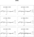
- FIG. 1 It is a lateral aberration diagram at the wide-angle end of the variable magnification optical system of Example 1.
- FIG. 2 It is a lateral aberration diagram at the telephoto end of the variable magnification optical system of Example 1.
- FIG. It is sectional drawing which shows the structure and the luminous flux at the wide-angle end of the variable magnification optical system of Example 2.
- FIG. 1 It is a partial cross-sectional view which shows the structure of the example which arranged the aperture diaphragm between the 3rd group and the 4th group, and the luminous flux.
- FIG. 1 It is sectional drawing which shows the structure and the luminous flux at the wide-angle end of the variable magnification optical system of Example 3.
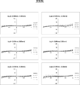
- FIG. 2 is a lateral aberration diagram at the wide-angle end of the variable magnification optical system of Example 3.
- FIG. 2 It is a lateral aberration diagram at the telephoto end of the variable magnification optical system of Example 3.
- FIG. 2 is sectional drawing which shows the structure and the luminous flux at the wide-angle end of the variable magnification optical system of Example 4.
- FIG. It is sectional drawing which shows the structure and the luminous flux at the wide-angle end of the variable magnification optical system of Example 5.
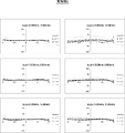
- FIG. It is a lateral aberration diagram at the wide-angle end of the variable magnification optical system of Example 5.
- FIG. It is a lateral aberration diagram at the telephoto end of the variable magnification optical system of Example 5.
- FIG. It is sectional drawing which shows the structure and the luminous flux at the wide-angle end of the variable magnification optical system of Example 6.
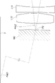
- FIG. 1 shows a cross-sectional view of a configuration at a wide-angle end of a variable magnification optical system according to an embodiment of the present disclosure.
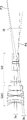
- FIG. 2 shows a cross-sectional view of the configuration and the luminous flux in each variable magnification state of this variable magnification optical system.
- the upper row labeled "Wide” shows the wide-angle end state
- the middle row labeled "Middle” shows the intermediate focal length state
- the lower row labeled "Tele” shows the telephoto end state.
- the reference numerals are given only to the upper figure.
- FIGS. 1 and 2 show a state in which the object is in focus at infinity.
- the examples shown in FIGS. 1 and 2 correspond to the variable magnification optical system of the first embodiment described later.
- This variable magnification optical system can be applied to, for example, a surveillance camera.
- the variable magnification optical system of FIG. 1 forms a bending optical path, and the upper left side of FIG. 1 is the object side and the lower right side of FIG. 1 is the image side.
- This variable magnification optical system includes a first group G1 having two mirrors and a plurality of variable magnification groups arranged in an optical path on the image side of the first group G1.
- the variable magnification group is a group that moves by changing the distance from the adjacent group at the time of scaling. The scaling is performed by moving these scaling groups.
- the first group G1, the second group G2, and the third group are continuously continuous from the object side to the image side along the optical path and have power. It is a zoom optical system including G3, a fourth group G4, and a fifth group G5.
- the third group G3 and the fourth group G4 are scaling groups, and when scaling from the wide-angle end to the telephoto end, the third group G3 moves to the image side and the fourth group G4 is an object. Move to the side.
- the movement locus of each group when scaling from the wide-angle end to the telephoto end is schematically shown by arrows under the third group G3 and the fourth group G4, respectively.
- each group in the example of FIG. 1 is configured as follows.
- the first group G1 includes a first mirror M1, a lens L11, a lens L12, and a second mirror M2.
- the second group G2 is composed of a second A subgroup G2A, a second B subgroup G2B, and a second C subgroup G2C in order from the object side to the image side.
- the second A subgroup G2A consists of two lenses, lenses La1 and La2, in this order from the object side to the image side.
- the second B subgroup G2B is composed of three lenses Lb1 to Lb3 in order from the object side to the image side.
- the second C subgroup G2C is composed of six lenses Lc1 to Lc6 in order from the object side to the image side.
- the third group G3 is composed of four lenses L31 to L34 in order from the object side to the image side.
- the fourth group G4 is composed of five lenses L41 to L45 in order from the object side to the image side.
- the fifth group G5 is composed of nine lenses L51 to L59 in order from the object side to the image side.
- the aperture stop St is arranged between the third group G3 and the fourth group G4.
- the aperture stop St in FIG. 1 does not indicate the shape and size, but indicates the position in the traveling direction of light. This illustration method for the aperture stop St is the same in other figures.
- FIG. 1 shows an example in which a parallel plate-shaped optical member PP is arranged between the variable magnification optical system and the image plane Sim on the assumption that the variable magnification optical system is applied to an image pickup apparatus.
- the optical member PP is a member that assumes various filters, a cover glass, and the like.
- the various filters are, for example, a low-pass filter, an infrared cut filter, and a filter that cuts a specific wavelength range.
- the optical member PP is a member having no power. It is also possible to configure the image pickup apparatus by omitting the optical member PP.
- the light incident on the variable magnification optical system from the object is first reflected to the object side by the first mirror M1, passes through the lens L11 and the lens L12 in this order, and then passes through the image side by the second mirror M2.
- the image plane Sim is reached via the second group G2, the third group G3, the fourth group G4, the fifth group G5, and the optical member PP. ..
- a ray passing through the apex of the optical surface of the variable magnification group will be referred to as a reference ray 2 and will be described.
- the optical plane constituting the scaling group includes a plane
- the plane is not included in the plane defining the reference ray 2.
- the optical surface of the lens is the lens surface.
- the reference ray 2 passes through the surface vertices of all the lens surfaces of the variable magnification group.
- the apex of the optical surface is conveniently set to the bottom point in the optical surface, that is, the apex when the air side is viewed from the optical element side.
- the reference ray 2 will be determined as.
- the direction of the reference ray 2 incident on the first group G1 from the object side is defined as the Z-axis direction.
- the surface including both the reference ray 2 incident on the first group G1 from the object side and the reference ray 2 passing between the two mirrors of the first group G1 is defined as a YZ surface. That is, the paper surface of FIG. 1 is the YZ surface.
- the left-right direction is the Z-axis direction
- the up-down direction is the Y-axis direction
- the direction perpendicular to the paper surface is the X-axis direction.
- the positive direction in the Z-axis direction is from left to right
- the positive direction in the Y-axis direction is from bottom to top
- the positive direction in the X-axis direction is from the back side to the front side of the paper.
- the first group G1 includes a first mirror M1 having a concave reflecting surface facing the object side.
- the first group G1 includes, in addition to the first mirror M1 having the above configuration, a second mirror M2 that reflects light from the first mirror M1 toward the object side toward the image side.
- the second mirror M2 has a convex reflecting surface facing the image side. According to the two mirrors having the above configuration, the light flux deflected to the object side by the reflection by the first mirror M1 is reflected by the second mirror M2 having a convex shape and deflected to the image side again, and the optical path is folded back. be able to. Therefore, it is possible to suppress an increase in the total length of the optical system in the Z direction due to telephoto by folding back the optical path while adopting a telephoto type configuration by combining the first mirror M1 and the second mirror M2. Further, since the mirror does not participate in chromatic aberration, using the above two mirrors is advantageous for chromatic aberration, which tends to be a problem in an optical system having a long focal length.
- the point where the reflection surface of the first mirror M1 and the reference ray 2 intersect is defined as the intersection point P1.
- the normal of the reflecting surface of the first mirror M1 at the intersection P1 is shown by a broken line.
- the angle formed by this normal and the reference ray 2 is defined as Ang0.
- the variable magnification optical system of this embodiment is configured so that the absolute value of Ang0 is 2 degrees or more.
- the first mirror M1 and the second mirror M2 are arranged on non-coaxial axes with each other. These points are significantly different from the optical system described in JP-A-2019-148790.
- the optical system of this comparative example includes a first mirror M1 and a second mirror M2 in which the reflecting surfaces of each other are arranged to face each other.
- the first mirror M1 and the second mirror M2 of the comparative example have a common optical axis, and the second mirror M2 is arranged in the optical path of the first mirror M1. Therefore, the first mirror M1 is configured in a ring shape having an aperture, and the central portion of the incident light flux to the variable magnification optical system is shielded by the second mirror M2, resulting in light loss.
- the comparative example has the following problems with wide angle of view.
- the wider the angle of view the smaller the incident luminous flux diameter, that is, the entrance pupil diameter. Therefore, in the comparative example in which the central portion of the incident light flux is shaded by the second mirror M2, the ratio of the light flux shaded by the second mirror M2 to the diameter of the incident light beam becomes large when the wide angle of view is promoted. It ends up. Due to such circumstances, it is difficult to widen the angle of view while ensuring the desired illuminance in the comparative example.
- variable magnification optical system of the present embodiment shown in FIG. 1 since the absolute value of Ang0 is configured to be 2 degrees or more, the light beam incident on the first mirror M1 from the object side is the first. After being reflected by the mirror M1, it can be ejected in a direction deviating from the incident optical path. As a result, as shown in FIG. 2, the second mirror M2 located on the object side of the first mirror M1 can be arranged at a position where the incident light flux to the variable magnification optical system is not shielded from light, unlike the comparative example. It becomes.
- the second mirror M2 can be configured not to block the incident light flux, which is advantageous for wide-angle. Further, even on the telephoto side where the incident luminous flux diameter is large, the central portion of the incident luminous flux is not shielded from light, so that the light amount loss as in the comparative example does not occur. Therefore, when compared with the same incident luminous flux diameter, the configuration of the present embodiment can capture more light than the comparative example.
- variable magnification optical system of the present embodiment all the light from the object, which is reflected by the first mirror M1 and then reflected by the second mirror M2, is the first mirror M1. It passes radially outside from the outer edge of.
- the radial direction referred to here means the radial direction of the reflecting surface of the first mirror M1 centered on the intersection P1.
- the first mirror M1 is provided with an opening for passing a light flux in the central portion.
- the first mirror M1 of the present embodiment does not need to be provided with an opening for passing a light beam, and therefore, when compared with the same incident light flux diameter, a larger amount of light is obtained than in the comparative example. be able to.
- the angle formed by the reference ray 2 incident on the first mirror M1 and the reference ray 2 emitted from the first mirror M1 is Ang1
- the light flux incident on the first mirror M1 By not exceeding the upper limit of the conditional expression (1), the occurrence of coma aberration due to the normal of the reflecting surface of the first mirror M1 at the intersection P1 being tilted with respect to the reference ray 2 is suppressed. be able to.
- variable magnification optical system preferably satisfies the following conditional expression (1-1), and even more preferably the following conditional expression (1-2). 4 ⁇
- FIG. 3 shows a partially enlarged view of the area around the intersection P2 and Ang2.
- variable magnification optical system satisfies the following conditional expression (2-1), and it is even more preferable that the following conditional expression (2-2) is satisfied. 5 ⁇
- FIG. 3 shows Ang3.
- the extension line on the second mirror side of the reference ray 2 emitted from the second mirror M2 is shown by a two-dot chain line.
- the reference ray 2 incident on the first mirror M1 is shown by a solid line above the second mirror M2.
- FIG. 3 is a schematic diagram for showing an angle, and the distance between the second mirror M2 and the reference ray 2 incident on the first mirror M1 in FIG. 3 is not accurate.
- the variable magnification optical system preferably satisfies the following conditional expression (3-1), and even more preferably the following conditional expression (3-2). 4 ⁇
- the first mirror M1 may be an optical element located closest to the object on the optical path among the optical elements having power included in the variable magnification optical system. In this way, the concerns described below can be avoided. If the refractive optics system is arranged in the optical path on the object side of the first mirror M1, the refractive optics system has a large aperture. In that case, the center of gravity of the variable magnification optical system may be biased toward the tip portion, resulting in poor weight balance and high cost.
- the first mirror M1 and the second mirror M2 are configured to be fixed to the image plane Sim.
- the first mirror M1 is a large component because it has a size that covers the entrance pupil diameter on the telephoto side.
- a mechanism for moving the first mirror M1 becomes unnecessary, and it is possible to avoid an increase in the size of the device.
- the mechanical structure around the second mirror M2 can be simplified. As a result, it becomes easy to prevent the mechanical parts around the second mirror M2 from blocking the light beam for image formation, which is advantageous in suppressing the light amount loss.
- the first group G1 is fixed to the image plane Sim. That is, it is preferable that all the optical elements constituting the first group G1 including the elements other than the mirror are fixed to the image plane Sim at the time of scaling. In this case, it is advantageous to simplify the configuration of the device.
- the first group G1 is configured to form an intermediate image Im inside the variable magnification optical system.
- the intermediate image Im is reimaged on the image plane Sim via the group on the image side of the intermediate image Im on the optical path.
- the variable magnification optical system As the re-imaging optical system, it is advantageous to reduce the diameter of each group.
- an intermediate image Im is formed in the optical path between the first group G1 and the second group G2. In FIGS. 1 and 2, only a part of the intermediate image Im is simply represented by a dotted line.
- Two or more scaling groups are arranged on the optical path on the image side of the intermediate image Im.
- a mechanical structure for moving the variable magnification group without blocking the light flux folded back by the first mirror M1 and the second mirror M2 is arranged. Becomes easier.
- the first group G1 may be configured to include the correction lens group Gh.
- the correction lens group Gh is preferably arranged in the first group G1 so as to be located on the optical path from the first mirror M1 to the second mirror M2 and on the optical path from the second mirror M2 to the intermediate image Im. .. In this case, the light beam passes through the correction lens group Gh twice.
- the correction lens group Gh is preferably composed of only one or more refracting lenses. If a mirror is used instead of the correction lens group Gh to perform the same correction, a folded optical path is further formed, which may cause light shielding due to interference between the luminous flux and the member. Alternatively, there is a risk that the optical system will become large in size in order to arrange the members so that this shading does not occur.
- a "refractive lens” is also simply referred to as a "lens”.
- the correction lens group Gh in FIG. 1 includes a lens L11 which is a negative lens and a lens L12 which is a positive lens.
- the lens L11 and the lens L12 in the example of FIG. 1 are spherical lenses.
- the first group G1 includes the correction lens group Gh
- at least one reflecting surface of the first mirror M1 and the second mirror M2 has a spherical shape.
- the correction lens group Gh arranged at the above position and the spherical mirror are combined, the coma aberration generated when the absolute value of Ang0 becomes 2 degrees or more, and the spherical surface generated by the spherical mirror. It becomes easy to correct the aberration. Further, according to the above-mentioned combination configuration, it becomes easy to construct a variable magnification optical system capable of achieving the object of the present invention without using an expensive aspherical mirror.
- the focal length of the first mirror M1 is f1 and the distance from the intersection P1 to the intersection P2 is DL12
- the following conditional expression (4) can be satisfied.
- the intersection P1 and the intersection P2 are the intersections defined above, respectively.
- variable magnification optical system preferably satisfies the following conditional expression (4-1), and even more preferably the following conditional expression (4-2). 0.4 ⁇ DL12 /
- the variable magnification optical system of FIG. 1 includes a first group G1 and a second group G2 arranged on the image side from the intermediate image Im in order from the object side to the image side along the optical path.
- the second group G2 may be configured such that adjacent subgroups are composed of a plurality of subgroups arranged on non-coaxial axes with each other. Since the first mirror M1 and the second mirror M2 are arranged on non-coaxial axes with each other, coma aberration due to eccentricity occurs. By arranging a plurality of subgroups in the second group G2 on non-coaxial axes, it is advantageous to correct the coma aberration associated with this eccentricity.
- the second group G2 includes a second A subgroup G2A having a positive power and a second B subgroup G2B having a negative power in order from the object side to the image side along the optical path.
- the second A subgroup G2A and the second B subgroup G2B may be configured to be arranged non-coaxial with each other. According to this configuration, it is advantageous to correct the coma aberration associated with the above eccentricity. Further, by arranging the second A subgroup G2A having a positive power at the position where the light flux diverges on the image side of the intermediate image Im, the divergence of the light flux can be suppressed. This is advantageous for reducing the diameter of the group on the image side of the second A subgroup G2A. By arranging the second B subgroup G2B having a power opposite to that of the second A subgroup G2A continuously to the second A subgroup G2A, it is advantageous for aberration correction.
- the second group G2 has a second A subgroup G2A having a positive power, a second B subgroup G2B having a negative power, and a positive one in order from the object side to the image side along the optical path. It may be configured to consist of a second C subgroup G2C having power.
- the second A subgroup G2A and the second B subgroup G2B are arranged so as to be non-coaxial with each other, and the second B subgroup G2B and the second C subgroup G2C are arranged so as to be non-coaxial with each other. May be good. According to this configuration, it is advantageous to correct the coma aberration associated with the above eccentricity.
- the powers of the adjacent subgroups so as to have opposite signs to each other, it is advantageous for aberration correction.
- the second C subgroup G2C having a positive power on the most image side of the second group G2 it is possible to give a converging action to the divergent light flux from the intermediate image Im toward the image side. It is more advantageous to reduce the diameter of the image side group than the 2 group G2.
- the secondA subgroup G2A and the secondC subgroup G2C may be arranged non-coaxially with each other or may be co-axised with each other. good. Further, the second A subgroup G2A and the variable magnification group may be arranged on the non-coaxial axis with each other, or may be arranged on the co-axis with each other. The second B subgroup G2B and the variable magnification group may be arranged non-coaxial with each other. The second C subgroup G2C and the variable magnification group may be arranged on the same axis with each other.
- the second A subgroup G2A may be configured to be a refractive optics system.
- the second B subgroup G2B may be configured to be a refractive optics system.
- the second C subgroup G2C may be configured to be a refractive optics system.
- the "refractive optical system" in the present specification is an optical system that does not include a reflecting optical element having power and includes only a refracting lens as an optical element having power. When a reflective optical element is used, the optical path is folded back, so that there is a possibility that a problem of light shielding due to interference between the light flux and the member may occur. Alternatively, there is a risk that the optical system will become large in size in order to arrange the members so that this shading does not occur. By using a refractive optics system, it is possible to avoid this problem.
- the second A subgroup G2A having a positive power and the second B subgroup G2B having a negative power are included.
- the focal distance of the 2A subgroup G2A is fG2A and the focal distance of the second B subgroup G2B is fG2B, it is preferable that the following conditional expression (5) is satisfied.
- the group is continuously arranged in the second B subgroup G2B on the image side of the second B subgroup G2B (in the example of FIG. 1, the second C subgroup). It is possible to prevent the outer diameter of G2C) from becoming large.
- the positive power of the second A subgroup G2A does not become too strong, so that the occurrence of spherical aberration on the telephoto side can be suppressed.
- the negative power of the second B subgroup G2B does not become too weak, it is advantageous to correct the coma aberration due to the eccentricity.
- variable magnification optical system satisfies the following conditional expression (5-1), and it is even more preferable that the following conditional expression (5-2) is satisfied.
- conditional expression (5-2) -1 ⁇ fG2A / fG2B ⁇ -0.01 (5) -0.75 ⁇ fG2A / fG2B ⁇ -0.02 (5-1) -0.5 ⁇ fG2A / fG2B ⁇ -0.04 (5-2)
- the second group G2 is fixed to the image plane Sim.
- a mechanism for moving the second group G2 becomes unnecessary, and it is possible to suppress an increase in the size of the device.
- the mechanical structure around the second group G2 can be simplified. This is advantageous in preventing the light flux from the first mirror M1 to the second mirror M2 from being shielded by the mechanical parts around the second group G2.
- variable magnification optical system consists of the first group G1 as a group having power in order from the object side to the image side along the optical path, the second group G2 arranged on the image side from the intermediate image Im, and the third group G3. And only the 4th group G4 and the succeeding group.
- the second group G2 consists of a plurality of subgroups in which adjacent subgroups are arranged on non-coaxial axes with each other, and is the most image-side subgroup of the second group G2 on the optical path (the second C subgroup in the example of FIG. 1).
- G2C has a positive power.
- the third group G3 is a refraction optical system having a negative power
- the fourth group G4 is a refraction optical system having a positive power.
- the second group G2 is fixed to the image plane Sim, and the third group G3 and the fourth group G4 move in opposite directions to each other.
- the most image-side subgroup of the second group G2, the third group G3, and the fourth group G4 have positive, negative, and positive powers, respectively. In this way, by arranging the powers of the adjacent subgroups so as to have opposite signs to each other, it is possible to give each group a strong power.
- the amount of movement of the third group G3 and the fourth group G4 at the time of scaling can be suppressed, which is advantageous for miniaturization of the optical system. Further, by converging the luminous flux diverged by the negative power third group G3 with the positive power fourth group G4 on the image side, it is possible to suppress the increase in the outer diameter of the subsequent group. ..
- the variable magnification optical system includes the above-mentioned third group G3 and fourth group G4, when the focal length of the third group G3 is fG3 and the focal length of the fourth group G4 is fG4, the following conditional expression (6) It is preferable to satisfy. By making sure that the power does not fall below the lower limit of the conditional expression (6), the power of the fourth group G4 does not become too weak, so that the amount of movement of the fourth group G4 at the time of scaling can be suppressed. This makes it possible to suppress an increase in the size of the optical system mainly in the Z-axis direction.
- the power of the third group G3 does not become too strong, the spherical aberration generated in the third group G3 can be suppressed.
- the power of the third group G3 does not become too weak, so that the movement amount of the fourth group G4 at the time of scaling can be suppressed. This makes it possible to suppress an increase in the size of the optical system mainly in the Z-axis direction. Further, since the power of the fourth group G4 does not become too strong, the spherical aberration generated in the fourth group G4 can be suppressed.
- variable magnification optical system satisfies the following conditional expression (6-1), and it is even more preferable that the following conditional expression (6-2) is satisfied.
- 6-1 the following conditional expression
- 6-2 the following conditional expression (6-2) is satisfied.
- the subsequent group consists of the 5th group G5 in the example of FIG.
- the subsequent group is not limited to the composition consisting of one group.
- Subsequent groups may be configured to consist of two groups, or three or more groups, whose mutual spacing changes upon scaling.
- the succeeding group consists of a plurality of groups
- the group on the most image side of the succeeding group may be configured to be fixed at the time of scaling. In this case, it is advantageous to simplify the device configuration.
- the aperture stop St is fixed to the image plane Sim at the time of scaling. It is preferable that the aperture diameter of the aperture stop St is variable in order to cope with various imaging conditions. In particular, it is preferable that the aperture diameter is variable in surveillance camera applications where shooting is performed day and night.
- the aperture throttle St is fixed at the time of scaling, the arrangement of the diaphragm mechanism for changing the aperture diameter becomes easy.
- the aperture throttle St is configured to move at the time of scaling, a conductor for supplying electric power to the driving component for driving the aperture throttle St is required, and there is a risk that the conductor will be disconnected. Occurs.
- the aperture stop St is fixed at the time of scaling, such a risk does not occur, so that the durability, which is important for monitoring applications, can be maintained higher.
- the aperture stop St may be configured to be arranged on the image side of the most image side surface of the variable magnification group on the most object side on the optical path.
- the arrangement of the diaphragm mechanism becomes easy, and it is advantageous for the miniaturization of the diaphragm mechanism.
- the most image-side surface of the variable magnification group on the most object side is the object-side surface of the lens L34 of the third group G3.
- the aperture stop St is configured to be arranged between the most object-side surface of the most object-side scaling group and the most image-side surface of the most image-side scaling group on the optical path.
- the surface on the object side of the variable magnification group on the most object side is the surface on the object side of the lens L31 of the third group G3, and the surface on the image side of the variable magnification group on the image side is the surface on the image side.
- the aperture stop St is arranged at the air spacing between the third group G3 and the fourth group G4.
- the aperture stop St is preferably arranged at a position where a part of the image forming region is not shielded from light when the aperture stop St is stopped down. Therefore, the position of the aperture stop St is from the point where the upper ray of the on-axis luminous flux and the upper ray of the off-axis luminous flux intersect (hereinafter referred to as point P3) to the lower ray of the on-axis luminous flux and the lower ray of the off-axis luminous flux. It is preferably within the range up to the point where and (hereinafter referred to as point P4) intersect.
- the luminous flux whose main ray is the reference ray 2 is referred to as an on-axis luminous flux
- the luminous flux whose main ray is not the reference ray 2 is referred to as an off-axis luminous flux.
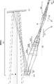
- FIG. 4A shows an example in which the aperture stop St is arranged between the second group G2C and the third group G3.
- FIG. 4A also shows an on-axis luminous flux 3a, an off-axis luminous flux 3b, the above points P3, and points P4.
- the opening throttle St is arranged between the 2nd C subgroup G2C and the 3rd group G3, the range from the point P3 to the point P4 is in the vicinity of the 3rd group G3 as shown in FIG.
- the distance between the second C subgroup G2C and the opening diaphragm St becomes wider at the wide angle end. Therefore, the distance between the second C subgroup G2C and the third group G3 also becomes wide, which leads to an increase in the total optical length.
- FIG. 4B shows an example in which the aperture stop St is arranged between the third group G3 and the fourth group G4.
- the off-axis luminous flux 3b ejected from the second C subgroup G2C and incident on the third group G3 is diverged by the negative power third group G3. Therefore, the tilt angle of the off-axis luminous flux 3b emitted from the third group G3 with respect to the optical axis Z is smaller than the tilt angle of the off-axis luminous flux 3b emitted from the second C subgroup G2C with respect to the optical axis Z. Therefore, the points P3 and P4 are located closer to the image side than in the case where the aperture stop St is arranged between the second C subgroup G2C and the third group G3.
- the aperture stop St By arranging the aperture stop St on the object side of the most image-side variable magnification group on the object side, it is advantageous to suppress the enlargement in the radial direction. If the aperture stop St is arranged on the image side of the most image-side surface of the variable magnification group on the image-side side, more light rays under the off-axis luminous flux must pass through, so that the third There is a risk that the outer diameter of group G3 will increase.
- variable magnification optical system of the present disclosure can be variously modified within a range that does not deviate from the gist of the technique of the present disclosure.
- the number of optical elements included in each group and the number of variable magnification groups can be arbitrarily selected.
- Each group is not limited to the configuration consisting of a plurality of optical elements, and may be configured to be composed of one optical element.
- the example of FIG. 1 is a zoom optical system
- the variable magnification optical system of the present disclosure may be a varifocal optical system.
- the above-mentioned preferable configuration and possible configuration can be any combination, and it is preferable that they are appropriately and selectively adopted according to the required specifications.
- variable magnification optical system of the present disclosure The cross-sectional views of the variable magnification optical system of the first embodiment are shown in FIGS. 1 and 2, and the configuration and the method of illustration thereof are as described above.
- the first group G1, the second group G2, the third group G3, the opening aperture St, and the fourth group are sequentially arranged from the object side to the image side along the optical path.
- It is a zoom optical system including G4 and the fifth group G5.
- An intermediate image Im is formed in the optical path between the first group G1 and the second group G2.
- the first group G1 includes a first mirror M1, a second mirror M2, and a correction lens group Gh.
- the correction lens group Gh includes a lens L11 and a lens L12.
- the second group G2 is composed of a second A subgroup G2A, a second B subgroup G2B, and a second C subgroup G2C in order from the object side to the image side.
- the second A subgroup G2A consists of two lenses, lenses La1 and La2, in this order from the object side to the image side.
- the second B subgroup G2B is composed of three lenses Lb1 to Lb3 in order from the object side to the image side.
- the second C subgroup G2C is composed of six lenses Lc1 to Lc6 in order from the object side to the image side.
- the second A subgroup G2A, the second B subgroup G2B, and the second C subgroup G2C are arranged non-coaxially with each other.
- the second group G2C, the third group G3, the aperture stop St, the fourth group G4, and the fifth group G5 are arranged on the same axis with each other.
- the third group G3 is composed of four lenses L31 to L34 in order from the object side to the image side.
- the fourth group G4 is composed of five lenses L41 to L45 in order from the object side to the image side.
- the fifth group G5 is composed of nine lenses L51 to L59 in order from the object side to the image side.
- the basic lens data is shown in Tables 1A and 1B, the coordinate data of the variable magnification group is shown in Table 2, and the specifications are shown in Table 3.
- the basic lens data is divided into two tables, Table 1A and Table 1B, in order to avoid lengthening one table.
- Table 1A shows the first group G1 and the second group G2
- Table 1B shows the third group G3, the aperture stop St, the fourth group G4, the fifth group G5, and the optical member PP.
- each table the values in the XYZ coordinate system using the above-mentioned X-axis, Y-axis, and Z-axis are shown with the point O shown in FIG. 1 as the origin.
- Tables 1A and 1B show the components along the optical path.
- each column will be described.
- the plane number including the point O and perpendicular to the Z axis is set as the first plane, and the plane number is shown when the number is increased one by one toward the image side along the optical path.
- the symbol "(St)" is also entered in the "surface number” column of the surface corresponding to the aperture stop St.
- the radius of curvature of each surface is shown in the column of "radius of curvature".
- the sign of the radius of curvature the sign of the surface having the convex surface facing the object side is positive, and the sign of the surface having the convex surface facing the image side is negative.
- the coordinates in the XYZ coordinate system of the center of curvature of each surface are shown with respect to the point O, respectively.
- Table 2 shows the coordinates of each surface of the 3rd group G3 and the 4th group G4 for each zoom position.
- Tables 2 and 3 the values at each zoom position in the wide-angle end state, the intermediate focal length state, and the telephoto end state are shown in the columns described as "Wide”, “Middle”, and "Tele”, respectively.
- the column of "on-axis luminous flux diameter" indicates the diameter of the on-axis luminous flux incident on the variable magnification optical system.
- the main rays having the maximum angle of view incident on the upper side and the lower side of the reference ray 2 will be referred to as an upper main ray and a lower main ray, respectively.
- ⁇ 1 is the incident angle of the upper main ray, that is, the angle formed by the upper main ray and the reference ray 2.
- ⁇ 2 is the incident angle of the lower main ray, that is, the angle formed by the lower main ray and the reference ray 2.
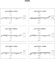
- FIG. 5 shows a lateral aberration diagram at the wide-angle end of the variable magnification optical system of Example 1.
- the left column shows the aberration in the sagittal direction
- the right column shows the aberration in the tangential direction.
- Aberrations on the d-line, F-line, C-line, and s-line are shown by solid lines, long dashed lines, alternate long and short dash lines, and dotted lines, respectively.
- the unit of the vertical axis is ⁇ m (micrometer).
- the coordinates are represented using an xyz coordinate system different from the above-mentioned XYZ coordinate system.
- the intersection of the reference ray 2 and the image plane Sim is set as the origin, and the x-axis, y-axis, and z-axis that are orthogonal to each other are used as described below.
- the direction of the reference ray 2 incident on the image plane Sim from the variable magnification optical system is defined as the z-axis direction
- the paper surface of FIG. 1 is defined as the yz plane
- the direction perpendicular to the paper surface is defined as the x-axis direction.
- the positive direction in the z-axis direction is the direction from the variable magnification optical system toward the image plane Sim
- the positive direction in the y-axis direction is the direction in which the first mirror M1 is located with respect to the reference ray 2 incident on the image plane Sim, the x-axis.
- the positive direction is from the back side of the paper to the front side.
- FIG. 6 shows a lateral aberration diagram at the telephoto end of the variable magnification optical system of Example 1. Also in FIG. 6, the aberration in the sagittal direction is shown in the left column, and the aberration in the tangential direction is shown in the right column.
- the illustration method of FIG. 6 is basically the same as that of FIG. 5 and 6 show aberrations in the state of being in focus on an infinity object.
- FIG. 7 shows a cross-sectional view and a luminous flux at the wide-angle end of the variable magnification optical system of Example 2.
- the first group G1, the second group G2, the third group G3, the opening aperture St, and the fourth group are sequentially arranged from the object side to the image side along the optical path.
- It is a zoom optical system including G4 and the fifth group G5.
- An intermediate image Im is formed in the optical path between the first group G1 and the second group G2.
- the first group G1 includes a first mirror M1, a second mirror M2, and a correction lens group Gh.
- the correction lens group Gh consists of two lenses.
- the second group G2 is composed of a second A subgroup G2A, a second B subgroup G2B, and a second C subgroup G2C in order from the object side to the image side.
- the second A subgroup G2A consists of two lenses.
- the second B subgroup G2B consists of three lenses.
- the second C subgroup G2C consists of six lenses.
- the second A subgroup G2A, the second B subgroup G2B, and the second C subgroup G2C are arranged non-coaxially with each other.
- the second group G2C, the third group G3, the aperture stop St, the fourth group G4, and the fifth group G5 are arranged on the same axis with each other.
- the third group G3 consists of four lenses.
- the fourth group G4 consists of five lenses.
- the fifth group G5 consists of nine lenses. The above is the outline of the variable magnification optical system of the second embodiment.
- variable magnification optical system of Example 2 the basic lens data is shown in Tables 4A and 4B, the coordinate data of the variable magnification group is shown in Table 5, the specifications are shown in Table 6, and the lateral aberration diagram at the wide-angle end is shown in FIG. The lateral aberration diagram at the telephoto end is shown in FIG.
- FIG. 10 shows a cross-sectional view and a luminous flux at the wide-angle end of the variable magnification optical system of Example 3.
- the variable magnification optical system of Example 3 has the same configuration as the outline of the variable magnification optical system of Example 2.
- the basic lens data is shown in Tables 7A and 7B
- the coordinate data of the variable magnification group is shown in Table 8
- the specifications are shown in Table 9
- the lateral aberration diagram at the wide-angle end is shown in FIG.
- the lateral aberration diagram at the telephoto end is shown in FIG.
- FIG. 13 shows a cross-sectional view and a luminous flux at the wide-angle end of the variable magnification optical system of Example 4.
- the variable magnification optical system of Example 4 has the same configuration as the outline of the variable magnification optical system of Example 2.
- the basic lens data is shown in Tables 10A and 10B
- the coordinate data of the variable magnification group is shown in Table 11
- the specifications are shown in Table 12
- the lateral aberration diagram at the wide-angle end is shown in FIG.
- the lateral aberration diagram at the telephoto end is shown in FIG.
- FIG. 16 shows a cross-sectional view and a luminous flux at the wide-angle end of the variable magnification optical system of Example 5.
- the variable magnification optical system of Example 5 has the same configuration as the outline of the variable magnification optical system of Example 2.
- the basic lens data is shown in Tables 13A and 13B
- the coordinate data of the variable magnification group is shown in Table 14
- the specifications are shown in Table 15,
- the lateral aberration diagram at the wide-angle end is shown in FIG.
- the lateral aberration diagram at the telephoto end is shown in FIG.
- FIG. 19 shows a cross-sectional view and a luminous flux at the wide-angle end of the variable magnification optical system of Example 6.
- the first group G1, the second group G2, the third group G3, the opening aperture St, and the fourth group are sequentially arranged from the object side to the image side along the optical path.
- It is a zoom optical system including G4, a fifth group G5, and a sixth group G6.
- An intermediate image Im is formed in the optical path between the first group G1 and the second group G2.
- the first group G1 includes a first mirror M1, a second mirror M2, and a correction lens group Gh.
- the correction lens group Gh consists of two lenses.
- the second group G2 is composed of a second A subgroup G2A, a second B subgroup G2B, and a second C subgroup G2C in order from the object side to the image side.
- the second A subgroup G2A consists of two lenses.
- the second B subgroup G2B consists of three lenses.
- the second C subgroup G2C consists of six lenses.
- the second A subgroup G2A, the second B subgroup G2B, and the second C subgroup G2C are arranged non-coaxially with each other.
- the second group G2C, the third group G3, the aperture stop St, the fourth group G4, the fifth group G5, and the sixth group G6 are arranged on the same axis with each other.
- the third group G3 consists of four lenses.
- the fourth group G4 consists of five lenses.
- the fifth group G5 consists of six lenses.
- the sixth group G6 consists of three lenses.
- variable magnification optical system of Example 6 the basic lens data is shown in Tables 16A and 16B, the coordinate data of the variable magnification group is shown in Tables 17A and 17B, the specifications are shown in Table 18, and the lateral aberration diagram at the wide-angle end is shown. 20 shows a lateral aberration diagram at the telephoto end in FIG. 21.
- Table 19 shows the corresponding values of
- the values shown in Table 19 are values based on the d-line.
- variable magnification optical systems of Examples 1 to 6 have a magnification ratio of 6.5 times or more, and in particular, the variable magnification optical systems of Examples 2 to 6 have a magnification ratio of 10 times or more.
- the variable magnification optical systems of Examples 1 to 6 achieve a wide angle of view while achieving such a high magnification ratio while suppressing light loss, are compactly configured, and are close to the visible light region. It has high optical performance with good correction of various aberrations in a wide range up to the infrared light region. Further, the variable magnification optical systems of Examples 1 to 6 are designed to reduce the load on the portion on the object side, and realize a telephoto system of reflection / refraction type variable magnification optical system while having an inexpensive configuration.
- FIG. 22 shows a schematic configuration diagram of an image pickup apparatus 10 using the variable magnification optical system 1 according to the embodiment of the present disclosure as an example of the image pickup apparatus according to the embodiment of the present disclosure.
- Examples of the image pickup apparatus 10 include a surveillance camera, a video camera, an electronic still camera, and the like.
- the image pickup apparatus 10 receives output signals from the variable magnification optical system 1, the filter 4 arranged on the image side of the variable magnification optical system 1, the image pickup element 5 arranged on the image side of the filter 4, and the image pickup element 5. It includes a signal processing unit 6 for arithmetic processing and a scaling control unit 7 for controlling the scaling of the scaling optical system 1.
- the image sensor 5 converts the optical image formed by the variable magnification optical system 1 into an electric signal.
- the image pickup device 5 for example, a CCD (Charge Coupled Device) or a CMOS (Complementary Metal Oxide Semiconductor) or the like can be used.
- the image pickup device 5 is arranged so that its image pickup surface coincides with the image plane of the variable magnification optical system 1.
- the image pickup device 10 may be configured to include a plurality of image pickup elements.
- the techniques of the present disclosure have been described above with reference to embodiments and examples, the techniques of the present disclosure are not limited to the above embodiments and examples, and various modifications are possible.
- the radius of curvature, the coordinates, the refractive index, the Abbe number, and the like of each optical element are not limited to the values shown in the above numerical examples, and may take other values.
Abstract
変倍光学系は、中間像を形成する第1群と、中間像より像側の光路上に配置され変倍の際に移動する複数の変倍群とを含む。第1群は、反射面を物体側に向けた第1ミラーと、反射面を像側に向けた第2ミラーとを含む。変倍の際、第1ミラーおよび第2ミラーは不動である。変倍群の光学面の頂点を通る光線を基準光線とした場合、第1ミラーの反射面と基準光線との交点における第1ミラーの反射面の法線と、基準光線との成す角度の絶対値が2度以上である。
Description
本開示の技術は、変倍光学系、および撮像装置に関する。
反射屈折型の変倍光学系として、特開2019-148790号公報に記載のものが知られている。
光量損失が少なく、より広画角であり、良好な光学性能を有する、小型の反射屈折型の変倍光学系が求められている。
上記事情に鑑み、本開示の技術は、光量損失を抑制しながら、広画角化が可能であり、小型化が図られ、良好な光学性能を有する反射屈折型の変倍光学系、およびこの変倍光学系を備えた撮像装置を提供することを目的とする。
本開示の技術の一態様に係る変倍光学系は、中間像を形成する第1群と、中間像より像側の光路上に配置され変倍の際に隣り合う群との間隔を変化させて移動する複数の変倍群とを含み、第1群は、凹面形状の反射面を物体側に向けた第1ミラーと、第1ミラーから物体側へ向かう光を像側へ反射する、凸面形状の反射面を像側に向けた第2ミラーとを含み、変倍の際、第1ミラーおよび第2ミラーは像面に対して固定され、変倍群の光学面の頂点を通る光線を基準光線とした場合、第1ミラーの反射面と基準光線との交点における第1ミラーの反射面の法線と、基準光線との成す角度の絶対値が2度以上であり、物体からの光のうち第1ミラーで反射された後に第2ミラーで反射された光は全て第1ミラーの外縁より径方向外側を通る。
第1群内には、第1ミラーから第2ミラーへの光路上、および第2ミラーから中間像への光路上に位置し、1つ以上の屈折レンズのみで構成された補正レンズ群が配置されることが好ましい。その場合、第1ミラーおよび第2ミラーの少なくとも一方の反射面は球面形状であるように構成してもよい。
第1ミラーへ入射する基準光線と、第1ミラーから射出された基準光線との成す角度をAng1とした場合、上記態様の変倍光学系は、下記条件式(1)を満足することが好ましく、下記条件式(1-1)を満足することがより好ましい。
4<|Ang1|<30 (1)
6<|Ang1|<20 (1-1)
4<|Ang1|<30 (1)
6<|Ang1|<20 (1-1)
第2ミラーへ入射する基準光線と、第2ミラーから射出された基準光線との成す角度をAng2とした場合、上記態様の変倍光学系は、下記条件式(2)を満足することが好ましく、下記条件式(2-1)を満足することがより好ましい。
5<|Ang2|<50 (2)
10<|Ang2|<40 (2-1)
5<|Ang2|<50 (2)
10<|Ang2|<40 (2-1)
第1ミラーへ入射する基準光線と、第2ミラーから射出された基準光線との成す角度をAng3とした場合、上記態様の変倍光学系は、下記条件式(3)を満足することが好ましく、下記条件式(3-1)を満足することがより好ましい。
4<|Ang3|<30 (3)
6<|Ang3|<25 (3-1)
4<|Ang3|<30 (3)
6<|Ang3|<25 (3-1)
第1ミラーの反射面は球面形状であり、第1ミラーの焦点距離をf1、第1ミラーの反射面と基準光線との交点から、第2ミラーの反射面と基準光線との交点までの距離をDL12とした場合、上記態様の変倍光学系は、下記条件式(4)を満足することが好ましく、下記条件式(4-1)を満足することがより好ましい。
0.4<DL12/|f1|<0.99 (4)
0.6<DL12/|f1|<0.95 (4-1)
0.4<DL12/|f1|<0.99 (4)
0.6<DL12/|f1|<0.95 (4-1)
上記態様の変倍光学系は、光路に沿って物体側から像側へ順に連続して、第1群と、中間像より像側に配置された第2群とを含み、第2群は、光路に沿って最も物体側から像側へ順に連続して、正のパワーを有する第2A部分群と、負のパワーを有する第2B部分群とを含み、第2A部分群と第2B部分群とは互いに非共軸に配置されているように構成してもよい。
上記態様の変倍光学系が上記第2群を含む場合、変倍の際、第2群は像面に対して固定され、第2群は、光路に沿って物体側から像側へ順に、第2A部分群と、第2B部分群と、第2C部分群とからなり、第2B部分群と第2C部分群とは互いに非共軸に配置されるように構成してもよい。そして、第2A部分群の焦点距離をfG2A、第2B部分群の焦点距離をfG2Bとした場合、上記態様の変倍光学系は、下記条件式(5)を満足することが好ましく、下記条件式(5-1)を満足することがより好ましい。
-1<fG2A/fG2B<-0.01 (5)
-0.75<fG2A/fG2B<-0.02 (5-1)
-1<fG2A/fG2B<-0.01 (5)
-0.75<fG2A/fG2B<-0.02 (5-1)
上記態様の変倍光学系が上記第2群を含む場合、変倍の際、第2群は像面に対して固定され、第2群は、光路に沿って物体側から像側へ順に、第2A部分群と、第2B部分群と、第2C部分群とからなり、第2B部分群と第2C部分群とは互いに非共軸に配置され、第2C部分群は正のパワーを有する屈折光学系であるように構成してもよい。
上記態様の変倍光学系は、光路に沿って物体側から像側へ順に、パワーを有する群として、第1群と、中間像より像側に配置された第2群と、負のパワーを有する屈折光学系である第3群と、正のパワーを有する屈折光学系である第4群と、後続群とのみを備え、第2群は、隣り合う部分群が互いに非共軸に配置された複数の部分群からなり、光路上における第2群の最も像側の部分群は正のパワーを有し、変倍の際、第2群は像面に対して固定され、第3群と第4群とは互いに逆方向に移動するように構成してもよい。
上記態様の変倍光学系が上記第3群および第4群を備える構成において、第3群の焦点距離をfG3、第4群の焦点距離をfG4とした場合、上記態様の変倍光学系は、下記条件式(6)を満足することが好ましい。
-10<fG4/fG3<-1 (6)
-10<fG4/fG3<-1 (6)
上記態様の変倍光学系は、変倍の際に像面に対して固定されている絞りを含むことが好ましい。その場合、絞りは、光路上における最も物体側の変倍群の最も像側の面より像側に配置されていてもよい。あるいは、絞りは、光路上における、最も物体側の変倍群の最も物体側の面から、最も像側の変倍群の最も像側の面までの間に配置されていてもよい。
本開示の技術の別の態様に係る撮像装置は、上記態様の変倍光学系を備えている。
なお、本明細書の「~からなり」、「~からなる」は、挙げられた構成要素以外に、実質的にパワーを有さないレンズ、並びに、絞り、フィルタ、およびカバーガラス等のレンズ以外の光学要素、並びに、レンズフランジ、レンズバレル、撮像素子、および手振れ補正機構等の機構部分、等が含まれていてもよいことを意図する。
なお、本明細書において、群についての「正のパワーを有する」は、群全体として正のパワーを有することを意味する。同様に、群についての「負のパワーを有する」は、群全体として負のパワーを有することを意味する。「パワーを有する」とは、焦点距離の逆数が0でないことを意味する。レンズに関して用いている「パワー」は屈折力と同義である。
複合非球面レンズ(球面レンズと、その球面レンズ上に形成された非球面形状の膜とが一体的に構成されて、全体として1つの非球面レンズとして機能するレンズ)は、接合レンズとは見なさず、1枚のレンズとして扱う。非球面を含む光学素子に関するパワーの符号、および面形状は、近軸領域で考えることにする。
条件式で用いている「焦点距離」は、近軸焦点距離である。条件式の値は、無限遠物体に合焦した状態においてd線を基準とした場合の値である。本明細書に記載の「d線」、「C線」、「F線」、および「s線」は輝線である。本明細書においては、d線の波長は587.56nm(ナノメートル)、C線の波長は656.27nm(ナノメートル)、F線の波長は486.13nm(ナノメートル)、s線の波長は852.11nm(ナノメートル)として扱う。
本開示の技術によれば、光量損失を抑制しながら、広画角化が可能であり、小型化が図られ、良好な光学性能を有する反射屈折型の変倍光学系、およびこの変倍光学系を備えた撮像装置を提供することができる。
以下、本開示の技術に係る実施形態の一例について図面を参照して説明する。図1に、本開示の一実施形態に係る変倍光学系の広角端における構成の断面図を示す。図2に、この変倍光学系の各変倍状態における構成および光束の断面図を示す。図2では、「Wide」と付した上段に広角端状態を示し、「Middle」と付した中段に中間焦点距離状態を示し、「Tele」と付した下段に望遠端状態を示す。図の煩雑化を避けるため、符号は上段の図のみに付している。図1および図2では、無限遠物体に合焦している状態を示す。図1および図2に示す例は後述の実施例1の変倍光学系に対応している。この変倍光学系は例えば監視カメラ等に適用可能である。図1の変倍光学系は屈曲光路を形成しており、図1の左側上部が物体側、図1の右側下部が像側である。
この変倍光学系は、2つのミラーを有する第1群G1と、第1群G1より像側の光路に配置された複数の変倍群とを含む。変倍群は、変倍の際に隣り合う群との間隔を変化させて移動する群である。これらの変倍群が移動することによって変倍が行われる。
一例として、図1の例の変倍光学系は、光路に沿って物体側から像側へ順に連続して、パワーを有する群として、第1群G1と、第2群G2と、第3群G3と、第4群G4と、第5群G5とを含むズーム光学系である。この例では、第3群G3と第4群G4とが変倍群であり、広角端から望遠端への変倍の際、第3群G3は像側へ移動し、第4群G4は物体側へ移動する。図1では、第3群G3および第4群G4の下にそれぞれ、広角端から望遠端へ変倍する際の各群の移動軌跡を模式的に矢印で示している。
一例として、図1の例の各群は以下のように構成されている。第1群G1は、第1ミラーM1と、レンズL11と、レンズL12と、第2ミラーM2とからなる。第2群G2は、物体側から像側へ順に、第2A部分群G2Aと、第2B部分群G2Bと、第2C部分群G2Cとからなる。第2A部分群G2Aは、物体側から像側へ順に、レンズLa1~La2の2枚のレンズからなる。第2B部分群G2Bは、物体側から像側へ順に、Lb1~Lb3の3枚のレンズからなる。第2C部分群G2Cは、物体側から像側へ順に、Lc1~Lc6の6枚のレンズからなる。第3群G3は、物体側から像側へ順に、レンズL31~L34の4枚のレンズからなる。第4群G4は、物体側から像側へ順に、レンズL41~L45の5枚のレンズからなる。第5群G5は、物体側から像側へ順に、レンズL51~L59の9枚のレンズからなる。
図1の例では、第3群G3と第4群G4との間に開口絞りStが配置されている。なお、図1の開口絞りStは形状および大きさを示しているのではなく、光の進行方向における位置を示している。開口絞りStに関するこの図示方法は他の図においても同様である。
図1では、変倍光学系が撮像装置に適用されることを想定して、変倍光学系と像面Simとの間に平行平板状の光学部材PPが配置された例を示している。光学部材PPは、各種フィルタおよびカバーガラス等を想定した部材である。各種フィルタは、例えば、ローパスフィルタ、赤外線カットフィルタ、および特定の波長域をカットするフィルタである。光学部材PPはパワーを有しない部材である。光学部材PPを省略して撮像装置を構成することも可能である。
図1の例では、物体から変倍光学系に入射した光は、まず、第1ミラーM1で物体側へ反射され、レンズL11とレンズL12をこの順に経由した後、第2ミラーM2で像側へ反射され、レンズL12とレンズL11をこの順に経由した後、第2群G2、第3群G3、第4群G4、第5群G5、および光学部材PPを経由して像面Simに到達する。
以下では、変倍群の光学面の頂点を通る光線を基準光線2と称して説明する。但し、変倍群を構成する光学面が平面を含む場合は、その平面は基準光線2を定義する面に含めないことにする。レンズの光学面はレンズ面である。図1の例では、基準光線2は変倍群の全てのレンズ面の面頂点を通っている。なお、変倍群の光学面が凹面の場合は、その光学面内の最も底の点、すなわち、光学素子側から空気側を見た場合に頂点となる点を、便宜的に光学面の頂点として基準光線2を定めることにする。
また、以下では、互いに直交するX軸、Y軸、およびZ軸を用いて説明する。物体側から第1群G1に入射する基準光線2の方向をZ軸方向とする。物体側から第1群G1に入射する基準光線2と、第1群G1の上記2つのミラー間を通る基準光線2との両方を含む面をYZ面とする。すなわち、図1の紙面がYZ面である。図1においては、左右方向がZ軸方向、上下方向がY軸方向、紙面に垂直な方向がX軸方向となる。また、Z軸方向の正方向は左から右へ向かう方向、Y軸方向の正方向は下から上へ向かう方向、X軸方向の正方向は紙面の裏側から表側へ向かう方向とする。
第1群G1は、凹面形状の反射面を物体側に向けた第1ミラーM1を含む。入射光束を屈折光学系ではなく、第1ミラーM1の凹面形状の反射面で集光させることによって、高価な大口径の接合レンズを用いることなく軸上色収差の発生を抑えることができる。
第1群G1は、上記構成の第1ミラーM1に加え、第1ミラーM1から物体側へ向かう光を像側へ反射する第2ミラーM2を含む。第2ミラーM2は、凸面形状の反射面を像側に向けている。上記構成の2つのミラーによれば、第1ミラーM1での反射により物体側に偏向された光束を、凸面形状を持つ第2ミラーM2で反射して再度像側に偏向させて、光路を折り返すことができる。従って、第1ミラーM1と第2ミラーM2との組合せでテレフォトタイプの構成をとりながら、光路を折り返すことによって、望遠化に伴う光学系のZ方向の全長の増大を抑えることができる。また、ミラーは色収差に関与しないため、上記2枚のミラーを用いることによって長焦点距離の光学系で課題となりやすい色収差に関して有利となる。
第1ミラーM1の反射面と基準光線2とが交わる点を交点P1とする。図1では、交点P1における第1ミラーM1の反射面の法線を破線で示す。この法線と基準光線2との成す角度をAng0とする。本実施形態の変倍光学系は、Ang0の絶対値が2度以上となるように構成される。本実施形態の変倍光学系は、第1ミラーM1と第2ミラーM2とは互いに非共軸に配置されている。これらの点が、特開2019-148790号公報に記載の光学系とは大きく異なる。
ここで、比較例として、特開2019-148790号公報に記載の光学系について説明する。この比較例の光学系は、互いの反射面が対向配置された第1ミラーM1と第2ミラーM2とを備える。比較例の第1ミラーM1と第2ミラーM2とは共通の光軸を有し、第1ミラーM1の光路中に第2ミラーM2が配置されている。そのため、第1ミラーM1は開口を有するリング形状に構成され、変倍光学系への入射光束の中央部分が第2ミラーM2によって遮光される構成となり、光量損失が生じてしまう。また、比較例は広画角化についても以下に述べる不具合がある。一般に、広画角になるほど入射光束径、すなわち入射瞳径が小さくなる。従って、入射光束の中央部分が第2ミラーM2によって遮光される比較例では、広画角化を進めようとすると、入射光束径に対する、第2ミラーM2によって遮光される光束の比が大きくなってしまう。このような事情から、比較例では所望の照度を確保しながら広画角化を行うことが難しい。
これに対して図1に示す本実施形態の変倍光学系では、Ang0の絶対値が2度以上となるように構成されているため、物体側から第1ミラーM1に入射した光線は、第1ミラーM1で反射された後、その入射光路から逸れた方向へ射出することができる。これによって、図2に示すように、第1ミラーM1より物体側に位置する第2ミラーM2を、比較例とは異なり、変倍光学系への入射光束を遮光しない位置に配置することが可能となる。
上記配置によれば、広角側において、第2ミラーM2が入射光束を遮光しない構成が可能のため広画角化に有利となる。また、入射光束径が大きくなる望遠側においても、入射光束の中央部分が遮光されることが無いため、比較例で生じていたような光量損失は生じない。よって、同じ入射光束径で比べた場合、比較例よりも本実施形態の構成の方が多くの光を取り込むことができる。
また、本実施形態の変倍光学系では、図2に示すように、物体からの光のうち第1ミラーM1で反射された後に第2ミラーM2で反射された光は全て、第1ミラーM1の外縁より径方向外側を通る。なお、ここでいう径方向は、交点P1を中心にした第1ミラーM1の反射面の径方向を意味する。比較例では、第2ミラーM2で反射された光は第1ミラーM1内部を通るため、第1ミラーM1は中央部に光束を通すための開口が設けられている。これに対して、本実施形態の第1ミラーM1は、比較例と異なり、光束を通すための開口を設けなくてよいため、同じ入射光束径で比べた場合、比較例より多くの光量を得ることができる。
第1ミラーM1へ入射する基準光線2と、第1ミラーM1から射出された基準光線2との成す角度をAng1とした場合、下記条件式(1)を満足することが好ましい。条件式(1)の下限以下とならないようにすることによって、第1ミラーM1へ入射する光束が第2ミラーM2によって遮光されるのを抑制することができる。条件式(1)の上限以上とならないようにすることによって、交点P1における第1ミラーM1の反射面の法線が基準光線2に対して傾いていることに起因するコマ収差の発生を抑制することができる。より良好な特性を得るためには、変倍光学系は下記条件式(1-1)を満足することがより好ましく、下記条件式(1-2)を満足することがさらにより好ましい。
4<|Ang1|<30 (1)
6<|Ang1|<20 (1-1)
8<|Ang1|<15 (1-2)
4<|Ang1|<30 (1)
6<|Ang1|<20 (1-1)
8<|Ang1|<15 (1-2)
第2ミラーM2へ入射する基準光線2と、第2ミラーM2から射出された基準光線2との成す角度をAng2とした場合、下記条件式(2)を満足することが好ましい。第2ミラーM2の反射面と基準光線2とが交わる点を交点P2とする。一例として、図3に、交点P2周辺およびAng2の部分拡大図を示す。条件式(2)の下限以下とならないようにすることによって、第1ミラーM1から第2ミラーM2へ射出される光線が第1群G1より像側の構成要素によって遮光されるのを抑制することができる。条件式(2)の上限以上とならないようにすることによって、交点P2における第2ミラーM2の反射面の法線が、基準光線2に対して傾いていることに起因するコマ収差の発生を抑制することができる。より良好な特性を得るためには、変倍光学系は下記条件式(2-1)を満足することがより好ましく、下記条件式(2-2)を満足することがさらにより好ましい。
5<|Ang2|<50 (2)
10<|Ang2|<40 (2-1)
15<|Ang2|<35 (2-2)
5<|Ang2|<50 (2)
10<|Ang2|<40 (2-1)
15<|Ang2|<35 (2-2)
第1ミラーM1へ入射する基準光線2と、第2ミラーM2から射出された基準光線2との成す角度をAng3とした場合、下記条件式(3)を満足することが好ましい。一例として、図3にAng3を示す。図3では、第2ミラーM2から射出された基準光線2の第2ミラー側の延長線を二点鎖線で示す。また、図3では、第1ミラーM1へ入射する基準光線2を第2ミラーM2より上方の実線で示す。図3は角度を示すための模式図であり、図3における第2ミラーM2と第1ミラーM1へ入射する基準光線2との距離は正確なものではない。条件式(3)の下限以下とならないようにすることによって、第1ミラーM1から第2ミラーM2へ射出される光線が第1群G1より像側の光路に配置された構成要素によって遮光されるのを抑制することができる。条件式(3)の上限以上とならないようにすることによって、Y軸方向の光学系のサイズの増加を抑制することができる。より良好な特性を得るためには、変倍光学系は下記条件式(3-1)を満足することがより好ましく、下記条件式(3-2)を満足することがさらにより好ましい。
4<|Ang3|<30 (3)
6<|Ang3|<25 (3-1)
9<|Ang3|<20 (3-2)
4<|Ang3|<30 (3)
6<|Ang3|<25 (3-1)
9<|Ang3|<20 (3-2)
第1ミラーM1は、変倍光学系に含まれるパワーを有する光学素子のうち、光路上で最も物体側に位置する光学素子であってもよい。このようにした場合は、以下に述べる懸念事項を回避できる。仮に、第1ミラーM1よりも物体側の光路に屈折光学系を配置した場合は、その屈折光学系は大きな口径を有することになる。その場合、変倍光学系の重心が先端部の方に偏って位置し重量バランスが悪くなる虞があり、また、高コストになる虞がある。
変倍の際、第1ミラーM1および第2ミラーM2は像面Simに対して固定されているように構成される。第1ミラーM1は望遠側の入射瞳径をカバーするサイズとなるため大型部品となる。第1ミラーM1が変倍の際に固定されている構成とすることによって、第1ミラーM1を移動させるための機構が不要となり、装置の大型化を回避することができる。第2ミラーM2が変倍の際に固定されている構成とすることによって、第2ミラーM2周辺のメカ構造を簡素化することができる。これによって、第2ミラーM2周辺の機械部品が結像用の光束を遮光するのを回避することが容易となるため、光量損失の抑制に有利となる。
変倍の際、第1群G1は像面Simに対して固定されていることが好ましい。すなわち、ミラー以外の素子も含め、第1群G1を構成する全ての光学素子は変倍の際に像面Simに対して固定されていることが好ましい。このようにした場合は、装置の構成の簡素化に有利となる。
図2に示すように、第1群G1は、変倍光学系の内部に中間像Imを形成するように構成される。中間像Imは、光路上で中間像Imより像側の群を介して像面Sim上に再結像される。変倍光学系を再結像光学系とすることによって、各群の径を小さくすることに有利となる。本実施形態の変倍光学系では、第1群G1と第2群G2との間の光路に中間像Imが形成される。図1および図2では、中間像Imの一部のみを簡略的に点線で表している。
中間像Imより像側の光路上には2つ以上の変倍群が配置される。変倍群が中間像Imより像側に位置することによって、第1ミラーM1および第2ミラーM2で折り返された光束を遮光することなく、変倍群を移動させるためのメカ構造を配置することが容易となる。
第1群G1は、補正レンズ群Ghを含むように構成してもよい。補正レンズ群Ghは、第1ミラーM1から第2ミラーM2への光路上、および第2ミラーM2から中間像Imへの光路上に位置するように第1群G1内に配置されることが好ましい。このようにした場合は、光線が補正レンズ群Ghを2回通ることになる。上記位置に補正レンズ群Ghを配置することによって、Ang0の絶対値が2度以上となることによって発生するコマ収差を補正することが容易となる。
補正レンズ群Ghは、1つ以上の屈折レンズのみで構成されることが好ましい。仮に、補正レンズ群Ghの代わりにミラーを用いて同様の補正を行おうとすると、さらに折り返し光路が形成されるため、光束と部材との干渉に起因する遮光が生じる虞がある。あるいは、この遮光が生じないように部材を配置するために光学系が大型化してしまう虞がある。なお、本明細書においては、「屈折レンズ」を単に「レンズ」ともいう。
一例として、図1の補正レンズ群Ghは、負レンズであるレンズL11と、正レンズであるレンズL12とからなる。図1の例のレンズL11およびレンズL12は球面レンズである。上記のように光線が2回通る位置に補正レンズ群Ghを配置することによって、補正レンズ群Ghが非球面レンズを含まない場合でも、諸収差を良好に補正することが容易となる。
第1群G1が補正レンズ群Ghを含む場合、第1ミラーM1および第2ミラーM2の少なくとも一方の反射面は球面形状であることが好ましい。上記位置に配置された補正レンズ群Ghと球面形状のミラーとを組合せた構成によれば、Ang0の絶対値が2度以上となることによって発生するコマ収差、および球面形状のミラーによって発生する球面収差を補正することが容易となる。また、上記組合せの構成によれば、高価な非球面形状のミラーを使用することなく、本願発明の目的を達成可能な変倍光学系を構成することが容易となる。
第1ミラーM1の反射面が球面形状である構成において、第1ミラーM1の焦点距離をf1、交点P1から交点P2までの距離をDL12とした場合、下記条件式(4)を満足することが好ましい。交点P1および交点P2はそれぞれ上記で定義した交点である。条件式(4)の下限以下とならないようにすることによって、第2ミラーM2から中間像Imまでの距離の増大を抑えることができるため、主にZ軸方向のサイズの増加を抑制することができる。条件式(4)の上限以上とならないようにすることによって、中間像Imが第2ミラーM2に近づき過ぎないため、望遠側において第1ミラーM1から第2ミラーM2へ向かう光束と、中間像Imに連続して配置された群の端部(図1の例では第2A部分群G2Aの上端)との干渉を回避することができる。より良好な特性を得るためには、変倍光学系は下記条件式(4-1)を満足することがより好ましく、下記条件式(4-2)を満足することがさらにより好ましい。
0.4<DL12/|f1|<0.99 (4)
0.6<DL12/|f1|<0.95 (4-1)
0.75<DL12/|f1|<0.92 (4-2)
0.4<DL12/|f1|<0.99 (4)
0.6<DL12/|f1|<0.95 (4-1)
0.75<DL12/|f1|<0.92 (4-2)
図1の変倍光学系は、光路に沿って物体側から像側へ順に連続して、第1群G1と、中間像Imより像側に配置された第2群G2とを含む。第2群G2は、隣り合う部分群が互いに非共軸に配置された複数の部分群からなるように構成してもよい。第1ミラーM1と第2ミラーM2とは互いに非共軸に配置されているため、偏心に伴うコマ収差が発生する。第2群G2内の複数の部分群を互いに非共軸に配置することによって、この偏心に伴うコマ収差を補正することに有利となる。
例えば、第2群G2は、光路に沿って最も物体側から像側へ順に連続して、正のパワーを有する第2A部分群G2Aと、負のパワーを有する第2B部分群G2Bとを含み、第2A部分群G2Aと第2B部分群G2Bとは互いに非共軸に配置されるように構成してもよい。この構成によれば、上記の偏心に伴うコマ収差を補正することに有利となる。また、中間像Imより像側で光束が発散する位置に正のパワーを有する第2A部分群G2Aを配置することによって、光束の発散を抑えることができる。これによって、第2A部分群G2Aより像側の群の小径化に有利となる。第2A部分群G2Aに連続して、第2A部分群G2Aとは逆符号のパワーを有する第2B部分群G2Bを配置することによって、収差補正に有利となる。
より具体的には、第2群G2は、光路に沿って物体側から像側へ順に、正のパワーを有する第2A部分群G2Aと、負のパワーを有する第2B部分群G2Bと、正のパワーを有する第2C部分群G2Cとからなるように構成してもよい。その場合、第2A部分群G2Aと第2B部分群G2Bとは互いに非共軸に配置され、第2B部分群G2Bと第2C部分群G2Cとは互いに非共軸に配置されるように構成してもよい。この構成によれば、上記の偏心に伴うコマ収差を補正することに有利となる。また、隣り合う部分群のパワーが互いに逆符号となるように配置されることによって、収差補正に有利となる。さらに、第2群G2の最も像側に正のパワーを有する第2C部分群G2Cを配置することによって、中間像Imから像側へ向かう発散光束に対して収束作用を与えることができるため、第2群G2より像側の群の小径化に有利となる。
第2群G2が上記の3つの部分群からなる場合、第2A部分群G2Aと第2C部分群G2Cとは、互いに非共軸に配置されていてもよく、互いに共軸に配置されていてもよい。また、第2A部分群G2Aと変倍群とは互いに非共軸に配置されていてもよく、互いに共軸に配置されていてもよい。第2B部分群G2Bと変倍群とは互いに非共軸に配置されていてもよい。第2C部分群G2Cと変倍群とは互いに共軸に配置されていてもよい。
第2A部分群G2Aは屈折光学系であるように構成してもよい。第2B部分群G2Bは屈折光学系であるように構成してもよい。第2C部分群G2Cは屈折光学系であるように構成してもよい。なお、本明細書における「屈折光学系」は、パワーを有する反射光学素子を含まず、パワーを有する光学素子として屈折レンズのみを含む光学系である。反射光学素子を用いた場合は、光路を折り返すことになるため、光束と部材との干渉に起因する遮光の問題が生じる虞がある。あるいは、この遮光が生じないように部材を配置するために光学系が大型化してしまう虞がある。屈折光学系を用いることによって、この問題を回避することが可能となる。
第2群G2が光路に沿って最も物体側から像側へ順に連続して、正のパワーを有する第2A部分群G2Aと、負のパワーを有する第2B部分群G2Bとを含む構成において、第2A部分群G2Aの焦点距離をfG2A、第2B部分群G2Bの焦点距離をfG2Bとした場合、下記条件式(5)を満足することが好ましい。条件式(5)の下限以下とならないようにすることによって、第2A部分群G2Aの正のパワーが弱くなり過ぎないため、上記の偏心に伴うコマ収差を補正することに有利となる。また、第2B部分群G2Bの負のパワーが強くなり過ぎないため、第2B部分群G2Bの像側に第2B部分群G2Bに連続して配置された群(図1の例では第2C部分群G2C)の外径が大型化するのを抑制することができる。条件式(5)の上限以上とならないようにすることによって、第2A部分群G2Aの正のパワーが強くなり過ぎないため、望遠側における球面収差の発生を抑制することができる。また、第2B部分群G2Bの負のパワーが弱くなり過ぎないため、上記の偏心に伴うコマ収差を補正することに有利となる。より良好な特性を得るためには、変倍光学系は下記条件式(5-1)を満足することがより好ましく、下記条件式(5-2)を満足することがさらにより好ましい。
-1<fG2A/fG2B<-0.01 (5)
-0.75<fG2A/fG2B<-0.02 (5-1)
-0.5<fG2A/fG2B<-0.04 (5-2)
-1<fG2A/fG2B<-0.01 (5)
-0.75<fG2A/fG2B<-0.02 (5-1)
-0.5<fG2A/fG2B<-0.04 (5-2)
変倍の際、第2群G2は像面Simに対して固定されていることが好ましい。このようにした場合は、第2群G2を移動させるための機構が不要となり、装置の大型化を抑制することができる。また、第1群G1に近い第2群G2を固定することによって、第2群G2周辺のメカ構造を簡素化することができる。これによって、第1ミラーM1から第2ミラーM2へ向かう光束が、第2群G2周辺の機械部品によって遮光されるのを回避することに有利となる。
変倍光学系の好ましい一態様として、例えば、以下の構成を採ることができる。変倍光学系は、光路に沿って物体側から像側へ順に、パワーを有する群として、第1群G1と、中間像Imより像側に配置された第2群G2と、第3群G3と、第4群G4と、後続群とのみを備える。第2群G2は、隣り合う部分群が互いに非共軸に配置された複数の部分群からなり、光路上における第2群G2の最も像側の部分群(図1の例では第2C部分群G2C)は正のパワーを有する。第3群G3は、負のパワーを有する屈折光学系であり、第4群G4は、正のパワーを有する屈折光学系である。変倍の際、第2群G2は像面Simに対して固定され、第3群G3と第4群G4とは互いに逆方向に移動する。この構成では、第2群G2の最も像側の部分群、第3群G3、第4群G4が、それぞれ、正、負、正のパワーを有する。このように、隣り合う部分群のパワーが互いに逆符号となるように配置されることによって、各群に強いパワーを持たせることが可能となる。これによって、変倍の際の第3群G3および第4群G4の移動量を抑えることができるため、光学系の小型化に有利となる。また、負のパワーの第3群G3によって発散作用を受けた光束を、その像側の正のパワーの第4群G4で収束させることによって、後続群の外径の大型化を抑えることができる。
変倍光学系が上記の第3群G3と第4群G4を備える構成において、第3群G3の焦点距離をfG3、第4群G4の焦点距離をfG4とした場合、下記条件式(6)を満足することが好ましい。条件式(6)の下限以下とならないようにすることによって、第4群G4のパワーが弱くなり過ぎないため、変倍の際の第4群G4の移動量を抑制することができる。これによって、主にZ軸方向の光学系の大型化を抑制することができる。また、第3群G3のパワーが強くなり過ぎないため、第3群G3で発生する球面収差を抑制することができる。条件式(6)の上限以上とならないようにすることによって、第3群G3のパワーが弱くなり過ぎないため、変倍の際の第4群G4の移動量を抑制することができる。これによって、主にZ軸方向の光学系の大型化を抑制することができる。また、第4群G4のパワーが強くなり過ぎないため、第4群G4で発生する球面収差を抑制することができる。より良好な特性を得るためには、変倍光学系は下記条件式(6-1)を満足することがより好ましく、下記条件式(6-2)を満足することがさらにより好ましい。
-10<fG4/fG3<-1 (6)
-7<fG4/fG3<-1.5 (6-1)
-5<fG4/fG3<-2 (6-2)
-10<fG4/fG3<-1 (6)
-7<fG4/fG3<-1.5 (6-1)
-5<fG4/fG3<-2 (6-2)
後続群は、図1の例では、第5群G5からなる。しかし、後続群は1つの群からなる構成に限定されない。後続群は、変倍の際に相互間隔が変化する2つの群、又は3つ以上の群からなるように構成してもよい。後続群が複数の群からなる場合、後続群の最も像側の群は変倍の際に固定されているように構成してもよい。このようにした場合は、装置構成の簡素化に有利となる。
開口絞りStは、変倍の際に像面Simに対して固定されていることが好ましい。種々の撮影条件に対応するためには開口絞りStの開口径は可変であることが好ましい。特に、昼夜を問わず撮影が行われる監視カメラ用途では開口径が可変であることが好ましい。変倍の際に開口絞りStが固定されている構成を採ることによって、開口径を変化させる絞り機構の配置が容易となる。また、仮に、変倍の際に開口絞りStが移動するように構成した場合は、開口絞りStを駆動するための駆動部品への電力の供給を行う導線が必要となり、その導線が断線するリスクが生じる。これに対して、変倍の際に開口絞りStが固定されている構成ではそのようなリスクは生じないため監視用途として重要な耐久性をより高く保持することができる。
開口絞りStは、光路上における最も物体側の変倍群の最も像側の面より像側に配置されるように構成してもよい。このようにした場合は、絞り機構の配置が容易となり、また、絞り機構の小型化に有利となる。図1の例における最も物体側の変倍群の最も像側の面は、第3群G3のレンズL34の物体側の面である。
あるいは、開口絞りStは、光路上における、最も物体側の変倍群の最も物体側の面から、最も像側の変倍群の最も像側の面までの間に配置されるように構成してもよい。図1の例における、最も物体側の変倍群の最も物体側の面は、第3群G3のレンズL31の物体側の面であり、最も像側の変倍群の最も像側の面は、第4群G4のレンズL45の物体側の面である。
図1の例では、開口絞りStは第3群G3と第4群G4との間の空気間隔に配置されている。開口絞りStは、開口絞りStを絞った際に結像領域の一部が遮光されないような位置に配置することが好ましい。このため、開口絞りStの位置としては、軸上光束の上光線と軸外光束の上光線とが交わる点(以下、点P3という)から、軸上光束の下光線と軸外光束の下光線とが交わる点(以下、点P4という)までの範囲内であることが好ましい。なお、ここでは、主光線が基準光線2となる光束を軸上光束と称し、主光線が基準光線2ではない光束を軸外光束と称している。
比較例として、図4Aに第2C部分群G2Cと第3群G3との間に開口絞りStが配置された場合の例を示す。図4Aには、軸上光束3a、軸外光束3b、上記の点P3、および点P4も示す。第2C部分群G2Cと第3群G3との間に開口絞りStを配置する場合は、図4Aに示すように点P3から点P4までの範囲は第3群G3近傍となるため、第3群G3と第4群G4との間に開口絞りStを配置する場合に比べ、広角端で第2C部分群G2Cと開口絞りStとの間隔が広くなってしまう。従って、第2C部分群G2Cと第3群G3との間隔も広くなってしまい、光学全長の増大を招いてしまう。
図4Bに第3群G3と第4群G4との間に開口絞りStが配置された場合の例を示す。この場合、第2C部分群G2Cから射出して第3群G3に入射した軸外光束3bは負のパワーの第3群G3により発散作用を受ける。このため、第3群G3から射出した軸外光束3bの光軸Zに対する傾角は、第2C部分群G2Cから射出した軸外光束3bの光軸Zに対する傾角よりも、小さくなる。そのため、第2C部分群G2Cと第3群G3との間に開口絞りStを配置した場合に比べ、点P3および点P4がより像側に位置する。図4Bに示すように第3群G3と第4群G4との間に開口絞りStを配置した場合は、図4Aの例とは異なり第3群G3の物体側に開口絞りStが無いため、広角端での第2C部分群G2Cと第3群G3との間隔を短くすることができると同時に、変倍に必要な第3群G3の移動量を確保することができる。
開口絞りStが、最も像側の変倍群の最も像側の面より物体側に配置されることによって、径方向の大型化を抑制することに有利となる。仮に、開口絞りStが、最も像側の変倍群の最も像側の面より像側に配置された場合は、軸外光束の下側の光線をより多く通さなくてはならないため、第3群G3の外径が大型化する虞がある。
なお、図1には好ましい一態様の例を示すが、本開示の変倍光学系は、本開示の技術の主旨を逸脱しない範囲内において種々の変形が可能である。例えば、各群に含まれる光学素子の数、および変倍群の数は任意に選択可能である。各群は、複数の光学素子からなる構成に限らず、1つの光学素子からなる構成としてもよい。また、図1の例はズーム光学系であるが、本開示の変倍光学系は、バリフォーカル光学系であってもよい。
上述した好ましい構成および可能な構成は、任意の組合せが可能であり、要求される仕様に応じて適宜選択的に採用されることが好ましい。
次に、本開示の変倍光学系の数値実施例について説明する。
[実施例1]
実施例1の変倍光学系の断面図は図1および図2に示されており、その構成および図示方法は上述したとおりであるので、ここでは重複説明を一部省略する。実施例1の変倍光学系は、光路に沿って物体側から像側へ向かって順に、第1群G1と、第2群G2と、第3群G3と、開口絞りStと、第4群G4と、第5群G5とからなるズーム光学系である。第1群G1と第2群G2との間の光路に中間像Imが形成されている。広角端から望遠端への変倍の際に、第3群G3は像側へ移動し、第4群G4は物体側へ移動し、その他の群および開口絞りStは像面Simに対して固定されている。第1群G1は、第1ミラーM1と、第2ミラーM2と、補正レンズ群Ghとからなる。補正レンズ群Ghは、レンズL11と、レンズL12とからなる。第2群G2は、物体側から像側へ順に、第2A部分群G2Aと、第2B部分群G2Bと、第2C部分群G2Cとからなる。第2A部分群G2Aは、物体側から像側へ順に、レンズLa1~La2の2枚のレンズからなる。第2B部分群G2Bは、物体側から像側へ順に、Lb1~Lb3の3枚のレンズからなる。第2C部分群G2Cは、物体側から像側へ順に、Lc1~Lc6の6枚のレンズからなる。第2A部分群G2Aと、第2B部分群G2Bと、第2C部分群G2Cとは互いに非共軸に配置されている。第2C部分群G2Cと、第3群G3と、開口絞りStと、第4群G4と、第5群G5とは互いに共軸に配置されている。第3群G3は、物体側から像側へ順に、レンズL31~L34の4枚のレンズからなる。第4群G4は、物体側から像側へ順に、レンズL41~L45の5枚のレンズからなる。第5群G5は、物体側から像側へ順に、レンズL51~L59の9枚のレンズからなる。
実施例1の変倍光学系について、基本レンズデータを表1Aおよび表1Bに、変倍群の座標データを表2に、諸元を表3に示す。ここでは、1つの表の長大化を避けるため基本レンズデータを表1Aおよび表1Bの2つの表に分けて表示している。表1Aには第1群G1、および第2群G2を示し、表1Bには第3群G3、開口絞りSt、第4群G4、第5群G5、および光学部材PPを示す。
各表では、図1に示す点Oを原点として、上述したX軸、Y軸、Z軸を用いたXYZ座標系における値を示す。表1Aおよび表1Bでは光路に沿って構成要素を示している。以下、各欄について説明する。「面番号」の欄には、点Oを含みZ軸に垂直な平面を第1面とし、光路に沿って像側に向かうに従い1つずつ番号を増加させた場合の面番号を示す。開口絞りStに相当する面の「面番号」の欄には「(St)」という記号も記入している。
「曲率半径」の欄には各面の曲率半径を示す。曲率半径の符号は、物体側に凸面を向けた形状の面の符号を正、像側に凸面を向けた形状の面の符号を負とする。「座標」の「X」、「Y」、「Z」の欄にはそれぞれ、点Oを基準として、各面の曲率中心のXYZ座標系における座標を示す。
「法線の角度成分」の「X軸成分」および「Y軸成分」の欄にはそれぞれ、各面の曲率中心における面の法線がX軸方向と成す角度およびY軸方向と成す角度を示す。角度の符号は、各軸の正方向に向かって、時計回り方向の角度を正、反時計回り方向の角度を負とする。「nd」の欄には各構成要素のd線における屈折率を示す。「νd」の欄には各構成要素のd線基準のアッベ数を示す。但し、反射面に相当する面のndおよびνdの欄には「反射面」と記入している。「群名」の欄には各群の名称を示す。
第3群G3および第4群G4の座標は変倍に伴い変化するため、表2にズームポジション毎の第3群G3および第4群G4の各面の座標を示す。表2および表3では、広角端状態、中間焦点距離状態、望遠端状態の各ズームポジションにおける値をそれぞれ「Wide」、「Middle」、「Tele」と表記した欄に示す。
表3では、「軸上光束径」の欄には、変倍光学系に入射する軸上光束の直径を示す。以下では、像面Simにおいて、基準光線2より上側および下側に入射する最大画角の主光線をそれぞれ上側主光線および下側主光線と称することにする。表3において、θ1は上側主光線の入射角度、すなわち上側主光線と基準光線2との成す角度である。θ2は、下側主光線の入射角度、すなわち下側主光線と基準光線2との成す角度である。画角を計算する際には、X方向の長さが7.76mm(ミリメートル)、Y方向の長さが4.36mm(ミリメートル)の長方形の撮像エリアを考え、この長方形の対角方向の像位置で計算する。この長方形のアスペクト比は16:9である。変倍比は、広角端におけるtan(|θ1|)+tan(|θ2|)の値と、各ズームポジションにおけるtan(|θ1|)+tan(|θ2|)の値との比より求めている。
各表のデータにおいて、角度の単位としては度を用い、座標の単位としてはmm(ミリメートル)を用いているが、光学系は比例拡大又は比例縮小しても使用可能なため他の適当な単位を用いることもできる。また、以下に示す各表では所定の桁でまるめた数値を記載している。


図5に、実施例1の変倍光学系の広角端における横収差図を示す。図5では、左列にサジタル方向の収差を示し、右列にタンジェンシャル方向の収差を示す。d線、F線、C線、およびs線における収差をそれぞれ実線、長破線、一点鎖線、および点線で示す。縦軸の単位はμm(マイクロメートル)である。
なお、横収差図においては、上述したXYZ座標系とは異なるxyz座標系を用いて座標を表している。xyz座標系では、基準光線2と像面Simとの交点を原点とし、以下に述べる、互いに直交するx軸、y軸、およびz軸を用いている。変倍光学系から像面Simに入射する基準光線2の方向をz軸方向とし、図1の紙面をyz面とし、紙面に垂直な方向をx軸方向とする。また、z軸方向の正方向は変倍光学系から像面Simへ向かう方向、y軸方向の正方向は像面Simに入射する基準光線2に対して第1ミラーM1がある方向、x軸方向の正方向は紙面の裏側から表側へ向かう方向とする。図5では上記のxyz座標系の各座標における収差を示しており、この各座標の値を各収差図の(x、y)=の後に記入している。
図6に、実施例1の変倍光学系の望遠端における横収差図を示す。図6においても、左列にサジタル方向の収差を示し、右列にタンジェンシャル方向の収差を示す。図6の図示方法は基本的に図5と同様である。図5および図6は、無限遠物体に合焦した状態における収差を示す。
上記の実施例1に関する各データの記号、意味、記載方法、および図示方法は、特に断りが無い限り以下の実施例においても基本的に同様であるので、以下では重複説明を省略する。
[実施例2]
実施例2の変倍光学系の広角端における断面図と光束を図7に示す。実施例2の変倍光学系は、光路に沿って物体側から像側へ向かって順に、第1群G1と、第2群G2と、第3群G3と、開口絞りStと、第4群G4と、第5群G5とからなるズーム光学系である。第1群G1と第2群G2との間の光路に中間像Imが形成されている。広角端から望遠端への変倍の際に、第3群G3は像側へ移動し、第4群G4は物体側へ移動し、その他の群および開口絞りStは像面Simに対して固定されている。第1群G1は、第1ミラーM1と、第2ミラーM2と、補正レンズ群Ghとからなる。補正レンズ群Ghは2枚のレンズからなる。第2群G2は、物体側から像側へ順に、第2A部分群G2Aと、第2B部分群G2Bと、第2C部分群G2Cとからなる。第2A部分群G2Aは2枚のレンズからなる。第2B部分群G2Bは3枚のレンズからなる。第2C部分群G2Cは6枚のレンズからなる。第2A部分群G2Aと、第2B部分群G2Bと、第2C部分群G2Cとは互いに非共軸に配置されている。第2C部分群G2Cと、第3群G3と、開口絞りStと、第4群G4と、第5群G5とは互いに共軸に配置されている。第3群G3は4枚のレンズからなる。第4群G4は5枚のレンズからなる。第5群G5は9枚のレンズからなる。以上が実施例2の変倍光学系の概要である。
実施例2の変倍光学系の広角端における断面図と光束を図7に示す。実施例2の変倍光学系は、光路に沿って物体側から像側へ向かって順に、第1群G1と、第2群G2と、第3群G3と、開口絞りStと、第4群G4と、第5群G5とからなるズーム光学系である。第1群G1と第2群G2との間の光路に中間像Imが形成されている。広角端から望遠端への変倍の際に、第3群G3は像側へ移動し、第4群G4は物体側へ移動し、その他の群および開口絞りStは像面Simに対して固定されている。第1群G1は、第1ミラーM1と、第2ミラーM2と、補正レンズ群Ghとからなる。補正レンズ群Ghは2枚のレンズからなる。第2群G2は、物体側から像側へ順に、第2A部分群G2Aと、第2B部分群G2Bと、第2C部分群G2Cとからなる。第2A部分群G2Aは2枚のレンズからなる。第2B部分群G2Bは3枚のレンズからなる。第2C部分群G2Cは6枚のレンズからなる。第2A部分群G2Aと、第2B部分群G2Bと、第2C部分群G2Cとは互いに非共軸に配置されている。第2C部分群G2Cと、第3群G3と、開口絞りStと、第4群G4と、第5群G5とは互いに共軸に配置されている。第3群G3は4枚のレンズからなる。第4群G4は5枚のレンズからなる。第5群G5は9枚のレンズからなる。以上が実施例2の変倍光学系の概要である。
実施例2の変倍光学系について、基本レンズデータを表4Aおよび表4Bに、変倍群の座標データを表5に、諸元を表6に、広角端における横収差図を図8に、望遠端における横収差図を図9に示す。


[実施例3]
実施例3の変倍光学系の広角端における断面図と光束を図10に示す。実施例3の変倍光学系は、実施例2の変倍光学系の概要と同様の構成を有する。実施例3の変倍光学系について、基本レンズデータを表7Aおよび表7Bに、変倍群の座標データを表8に、諸元を表9に、広角端における横収差図を図11に、望遠端における横収差図を図12に示す。
実施例3の変倍光学系の広角端における断面図と光束を図10に示す。実施例3の変倍光学系は、実施例2の変倍光学系の概要と同様の構成を有する。実施例3の変倍光学系について、基本レンズデータを表7Aおよび表7Bに、変倍群の座標データを表8に、諸元を表9に、広角端における横収差図を図11に、望遠端における横収差図を図12に示す。


[実施例4]
実施例4の変倍光学系の広角端における断面図と光束を図13に示す。実施例4の変倍光学系は、実施例2の変倍光学系の概要と同様の構成を有する。実施例4の変倍光学系について、基本レンズデータを表10Aおよび表10Bに、変倍群の座標データを表11に、諸元を表12に、広角端における横収差図を図14に、望遠端における横収差図を図15に示す。
実施例4の変倍光学系の広角端における断面図と光束を図13に示す。実施例4の変倍光学系は、実施例2の変倍光学系の概要と同様の構成を有する。実施例4の変倍光学系について、基本レンズデータを表10Aおよび表10Bに、変倍群の座標データを表11に、諸元を表12に、広角端における横収差図を図14に、望遠端における横収差図を図15に示す。


[実施例5]
実施例5の変倍光学系の広角端における断面図と光束を図16に示す。実施例5の変倍光学系は、実施例2の変倍光学系の概要と同様の構成を有する。実施例5の変倍光学系について、基本レンズデータを表13Aおよび表13Bに、変倍群の座標データを表14に、諸元を表15に、広角端における横収差図を図17に、望遠端における横収差図を図18に示す。
実施例5の変倍光学系の広角端における断面図と光束を図16に示す。実施例5の変倍光学系は、実施例2の変倍光学系の概要と同様の構成を有する。実施例5の変倍光学系について、基本レンズデータを表13Aおよび表13Bに、変倍群の座標データを表14に、諸元を表15に、広角端における横収差図を図17に、望遠端における横収差図を図18に示す。


[実施例6]
実施例6の変倍光学系の広角端における断面図と光束を図19に示す。実施例6の変倍光学系は、光路に沿って物体側から像側へ向かって順に、第1群G1と、第2群G2と、第3群G3と、開口絞りStと、第4群G4と、第5群G5と、第6群G6とからなるズーム光学系である。第1群G1と第2群G2との間の光路に中間像Imが形成されている。広角端から望遠端への変倍の際に、第3群G3は像側へ移動し、第4群G4は物体側へ移動し、第5群G5は像側へ移動し、その他の群および開口絞りStは像面Simに対して固定されている。第1群G1は、第1ミラーM1と、第2ミラーM2と、補正レンズ群Ghとからなる。補正レンズ群Ghは2枚のレンズからなる。第2群G2は、物体側から像側へ順に、第2A部分群G2Aと、第2B部分群G2Bと、第2C部分群G2Cとからなる。第2A部分群G2Aは2枚のレンズからなる。第2B部分群G2Bは3枚のレンズからなる。第2C部分群G2Cは6枚のレンズからなる。第2A部分群G2Aと、第2B部分群G2Bと、第2C部分群G2Cとは互いに非共軸に配置されている。第2C部分群G2Cと、第3群G3と、開口絞りStと、第4群G4と、第5群G5と、第6群G6とは互いに共軸に配置されている。第3群G3は4枚のレンズからなる。第4群G4は5枚のレンズからなる。第5群G5は6枚のレンズからなる。第6群G6は3枚のレンズからなる。
実施例6の変倍光学系の広角端における断面図と光束を図19に示す。実施例6の変倍光学系は、光路に沿って物体側から像側へ向かって順に、第1群G1と、第2群G2と、第3群G3と、開口絞りStと、第4群G4と、第5群G5と、第6群G6とからなるズーム光学系である。第1群G1と第2群G2との間の光路に中間像Imが形成されている。広角端から望遠端への変倍の際に、第3群G3は像側へ移動し、第4群G4は物体側へ移動し、第5群G5は像側へ移動し、その他の群および開口絞りStは像面Simに対して固定されている。第1群G1は、第1ミラーM1と、第2ミラーM2と、補正レンズ群Ghとからなる。補正レンズ群Ghは2枚のレンズからなる。第2群G2は、物体側から像側へ順に、第2A部分群G2Aと、第2B部分群G2Bと、第2C部分群G2Cとからなる。第2A部分群G2Aは2枚のレンズからなる。第2B部分群G2Bは3枚のレンズからなる。第2C部分群G2Cは6枚のレンズからなる。第2A部分群G2Aと、第2B部分群G2Bと、第2C部分群G2Cとは互いに非共軸に配置されている。第2C部分群G2Cと、第3群G3と、開口絞りStと、第4群G4と、第5群G5と、第6群G6とは互いに共軸に配置されている。第3群G3は4枚のレンズからなる。第4群G4は5枚のレンズからなる。第5群G5は6枚のレンズからなる。第6群G6は3枚のレンズからなる。
実施例6の変倍光学系について、基本レンズデータを表16Aおよび表16Bに、変倍群の座標データを表17Aおよび表17Bに、諸元を表18に、広角端における横収差図を図20に、望遠端における横収差図を図21に示す。


表19に実施例1~6の変倍光学系について、|Ang0|および条件式(1)~(6)の対応値を示す。表19に示す値は、d線基準での値である。

実施例1~6の変倍光学系は変倍比が6.5倍以上あり、特に、実施例2~6の変倍光学系は変倍比が10倍以上ある。実施例1~6の変倍光学系は、このような高変倍比を達成しながらも、光量損失を抑制しつつ、広画角化を達成し、小型に構成され、可視光域から近赤外光域までの広い範囲で諸収差が良好に補正されて高い光学性能を有している。また、実施例1~6の変倍光学系は、物体側の部分への荷重の低減化が図られ、安価な構成ながらも望遠系の反射屈折型の変倍光学系を実現している。
次に、本開示の実施形態に係る撮像装置について説明する。図22に、本開示の実施形態の撮像装置の一例として、本開示の実施形態に係る変倍光学系1を用いた撮像装置10の概略構成図を示す。撮像装置10としては、例えば、監視カメラ、ビデオカメラ、および電子スチルカメラ等を挙げることができる。
撮像装置10は、変倍光学系1と、変倍光学系1の像側に配置されたフィルタ4と、フィルタ4の像側に配置された撮像素子5と、撮像素子5からの出力信号を演算処理する信号処理部6と、変倍光学系1の変倍を制御する変倍制御部7とを備える。
撮像素子5は、変倍光学系1により形成される光学像を電気信号に変換する。撮像素子5としては例えばCCD(Charge Coupled Device)又はCMOS(Complementary Metal Oxide Semiconductor)等を用いることができる。撮像素子5は、その撮像面が変倍光学系1の像面に一致するように配置される。なお、図22では1つの撮像素子5のみ図示しているが、撮像装置10は複数の撮像素子を備えるように構成してもよい。
以上、実施形態および実施例を挙げて本開示の技術を説明したが、本開示の技術は上記実施形態および実施例に限定されず、種々の変形が可能である。例えば、各光学素子の曲率半径、座標、屈折率、およびアッベ数等は、上記各数値実施例で示した値に限定されず、他の値をとり得る。
本明細書に記載された全ての文献、特許出願、および技術規格は、個々の文献、特許出願、および技術規格が参照により取り込まれることが具体的かつ個々に記された場合と同程度に、本明細書中に参照により取り込まれる。
Claims (20)
- 中間像を形成する第1群と、前記中間像より像側の光路上に配置され変倍の際に隣り合う群との間隔を変化させて移動する複数の変倍群とを含み、
前記第1群は、凹面形状の反射面を物体側に向けた第1ミラーと、前記第1ミラーから物体側へ向かう光を像側へ反射する、凸面形状の反射面を像側に向けた第2ミラーとを含み、
変倍の際、前記第1ミラーおよび前記第2ミラーは像面に対して固定され、
前記変倍群の光学面の頂点を通る光線を基準光線とした場合、
前記第1ミラーの前記反射面と前記基準光線との交点における前記第1ミラーの反射面の法線と、前記基準光線との成す角度の絶対値が2度以上であり、
物体からの光のうち前記第1ミラーで反射された後に前記第2ミラーで反射された光は全て前記第1ミラーの外縁より径方向外側を通る変倍光学系。 - 前記第1群内には、前記第1ミラーから前記第2ミラーへの光路上、および前記第2ミラーから前記中間像への光路上に位置し、1つ以上の屈折レンズのみで構成された補正レンズ群が配置される請求項1に記載の変倍光学系。
- 前記第1ミラーおよび前記第2ミラーの少なくとも一方の反射面は球面形状である請求項2に記載の変倍光学系。
- 前記第1ミラーへ入射する前記基準光線と、前記第1ミラーから射出された前記基準光線との成す角度をAng1とした場合、
4<|Ang1|<30 (1)
で表される条件式(1)を満足する請求項1から3のいずれか1項に記載の変倍光学系。 - 前記第2ミラーへ入射する前記基準光線と、前記第2ミラーから射出された前記基準光線との成す角度をAng2とした場合、
5<|Ang2|<50 (2)
で表される条件式(2)を満足する請求項1から4のいずれか1項に記載の変倍光学系。 - 前記第1ミラーへ入射する前記基準光線と、前記第2ミラーから射出された前記基準光線との成す角度をAng3とした場合、
4<|Ang3|<30 (3)
で表される条件式(3)を満足する請求項1から5のいずれか1項に記載の変倍光学系。 - 前記第1ミラーの反射面は球面形状であり、
前記第1ミラーの焦点距離をf1、
前記第1ミラーの前記反射面と前記基準光線との交点から、前記第2ミラーの前記反射面と前記基準光線との交点までの距離をDL12とした場合、
0.4<DL12/|f1|<0.99 (4)
で表される条件式(4)を満足する請求項1から6のいずれか1項に記載の変倍光学系。 - 光路に沿って物体側から像側へ順に連続して、前記第1群と、前記中間像より像側に配置された第2群とを含み、
前記第2群は、光路に沿って最も物体側から像側へ順に連続して、正のパワーを有する第2A部分群と、負のパワーを有する第2B部分群とを含み、
前記第2A部分群と前記第2B部分群とは互いに非共軸に配置されている請求項1から7のいずれか1項に記載の変倍光学系。 - 変倍の際、前記第2群は像面に対して固定され、
前記第2群は、光路に沿って物体側から像側へ順に、前記第2A部分群と、前記第2B部分群と、第2C部分群とからなり、
前記第2B部分群と前記第2C部分群とは互いに非共軸に配置され、
前記第2A部分群の焦点距離をfG2A、
前記第2B部分群の焦点距離をfG2Bとした場合、
-1<fG2A/fG2B<-0.01 (5)
で表される条件式(5)を満足する請求項8に記載の変倍光学系。 - 変倍の際、前記第2群は像面に対して固定され、
前記第2群は、光路に沿って物体側から像側へ順に、前記第2A部分群と、前記第2B部分群と、第2C部分群とからなり、
前記第2B部分群と前記第2C部分群とは互いに非共軸に配置され、
前記第2C部分群は正のパワーを有する屈折光学系である請求項8又は9に記載の変倍光学系。 - 光路に沿って物体側から像側へ順に、パワーを有する群として、前記第1群と、前記中間像より像側に配置された第2群と、負のパワーを有する屈折光学系である第3群と、正のパワーを有する屈折光学系である第4群と、後続群とのみを備え、
前記第2群は、隣り合う部分群が互いに非共軸に配置された複数の部分群からなり、光路上における前記第2群の最も像側の部分群は正のパワーを有し、
変倍の際、前記第2群は像面に対して固定され、前記第3群と前記第4群とは互いに逆方向に移動する請求項1から10のいずれか1項に記載の変倍光学系。 - 前記第3群の焦点距離をfG3、
前記第4群の焦点距離をfG4とした場合、
-10<fG4/fG3<-1 (6)
で表される条件式(6)を満足する請求項11に記載の変倍光学系。 - 変倍の際に像面に対して固定されている絞りを含み、
光路上における最も物体側の前記変倍群の最も像側の面より像側に前記絞りが配置されている請求項1から12のいずれか1項に記載の変倍光学系。 - 変倍の際に像面に対して固定されている絞りを含み、
光路上における、最も物体側の前記変倍群の最も物体側の面から、最も像側の前記変倍群の最も像側の面までの間に前記絞りが配置されている請求項1から12のいずれか1項に記載の変倍光学系。 - 6<|Ang1|<20 (1-1)
で表される条件式(1-1)を満足する請求項4に記載の変倍光学系。 - 10<|Ang2|<40 (2-1)
で表される条件式(2-1)を満足する請求項5に記載の変倍光学系。 - 6<|Ang3|<25 (3-1)
で表される条件式(3-1)を満足する請求項6に記載の変倍光学系。 - 0.6<DL12/|f1|<0.95 (4-1)
で表される条件式(4-1)を満足する請求項7に記載の変倍光学系。 - -0.75<fG2A/fG2B<-0.02 (5-1)
で表される条件式(5-1)を満足する請求項9に記載の変倍光学系。 - 請求項1から19のいずれか1項に記載の変倍光学系を備えた撮像装置。
Priority Applications (1)
| Application Number | Priority Date | Filing Date | Title |
|---|---|---|---|
| JP2022572050A JP7317252B2 (ja) | 2020-12-21 | 2021-12-02 | 変倍光学系および撮像装置 |
Applications Claiming Priority (2)
| Application Number | Priority Date | Filing Date | Title |
|---|---|---|---|
| JP2020-211714 | 2020-12-21 | ||
| JP2020211714 | 2020-12-21 |
Publications (1)
| Publication Number | Publication Date |
|---|---|
| WO2022138054A1 true WO2022138054A1 (ja) | 2022-06-30 |
Family
ID=82159505
Family Applications (1)
| Application Number | Title | Priority Date | Filing Date |
|---|---|---|---|
| PCT/JP2021/044335 WO2022138054A1 (ja) | 2020-12-21 | 2021-12-02 | 変倍光学系および撮像装置 |
Country Status (2)
| Country | Link |
|---|---|
| JP (1) | JP7317252B2 (ja) |
| WO (1) | WO2022138054A1 (ja) |
Citations (6)
| Publication number | Priority date | Publication date | Assignee | Title |
|---|---|---|---|---|
| US4971428A (en) * | 1989-03-27 | 1990-11-20 | Lenzar Optics Corporation | Catadioptric zoom lens |
| JPH11202208A (ja) * | 1997-10-27 | 1999-07-30 | Wescam Inc | 反射屈折光学系ズームレンズ組立体 |
| CN106772963A (zh) * | 2017-01-26 | 2017-05-31 | 西安应用光学研究所 | 全球面大口径折反式连续变焦光学系统 |
| JP2019148790A (ja) * | 2018-02-27 | 2019-09-05 | 富士フイルム株式会社 | 変倍光学系及び撮像装置 |
| CN110515189A (zh) * | 2019-09-27 | 2019-11-29 | Oppo广东移动通信有限公司 | 离轴折反式摄像头和电子装置 |
| WO2021085142A1 (ja) * | 2019-10-29 | 2021-05-06 | 富士フイルム株式会社 | 変倍光学系および撮像装置 |
-
2021
- 2021-12-02 JP JP2022572050A patent/JP7317252B2/ja active Active
- 2021-12-02 WO PCT/JP2021/044335 patent/WO2022138054A1/ja active Application Filing
Patent Citations (6)
| Publication number | Priority date | Publication date | Assignee | Title |
|---|---|---|---|---|
| US4971428A (en) * | 1989-03-27 | 1990-11-20 | Lenzar Optics Corporation | Catadioptric zoom lens |
| JPH11202208A (ja) * | 1997-10-27 | 1999-07-30 | Wescam Inc | 反射屈折光学系ズームレンズ組立体 |
| CN106772963A (zh) * | 2017-01-26 | 2017-05-31 | 西安应用光学研究所 | 全球面大口径折反式连续变焦光学系统 |
| JP2019148790A (ja) * | 2018-02-27 | 2019-09-05 | 富士フイルム株式会社 | 変倍光学系及び撮像装置 |
| CN110515189A (zh) * | 2019-09-27 | 2019-11-29 | Oppo广东移动通信有限公司 | 离轴折反式摄像头和电子装置 |
| WO2021085142A1 (ja) * | 2019-10-29 | 2021-05-06 | 富士フイルム株式会社 | 変倍光学系および撮像装置 |
Also Published As
| Publication number | Publication date |
|---|---|
| JPWO2022138054A1 (ja) | 2022-06-30 |
| JP7317252B2 (ja) | 2023-07-28 |
Similar Documents
| Publication | Publication Date | Title |
|---|---|---|
| JP5694508B2 (ja) | 変倍光学系および撮像装置 | |
| JP4317928B2 (ja) | ズームレンズ | |
| JP6685944B2 (ja) | ズームレンズおよび撮像装置 | |
| CN110501810B (zh) | 光学系统和摄像装置 | |
| JP2017161567A (ja) | ズームレンズ及びそれを有する撮像装置 | |
| JP6493896B2 (ja) | ズームレンズおよび撮像装置 | |
| KR101707874B1 (ko) | 촬상 광학계 | |
| JP6820878B2 (ja) | ズームレンズ及び撮像装置 | |
| JP6356639B2 (ja) | 変倍光学系および撮像装置 | |
| JP7109686B2 (ja) | 変倍光学系および撮像装置 | |
| JP2004093593A (ja) | ズームレンズ | |
| JP6815375B2 (ja) | 変倍光学系及び撮像装置 | |
| JP6815376B2 (ja) | 変倍光学系及び撮像装置 | |
| JP3723643B2 (ja) | 高変倍ズームレンズ系 | |
| WO2010084664A1 (ja) | ズームレンズ、ズームレンズを備えた光学機器、及び、ズームレンズの製造方法 | |
| JP2018194750A (ja) | ズームレンズおよび撮像装置 | |
| JP7085873B2 (ja) | ズームレンズ及び撮像装置 | |
| WO2022138054A1 (ja) | 変倍光学系および撮像装置 | |
| JP6649287B2 (ja) | ズームレンズおよび撮像装置 | |
| JP5578412B2 (ja) | 撮影レンズ、この撮影レンズを有する光学機器、及び、撮影レンズの製造方法 | |
| JP7043441B2 (ja) | ズームレンズ及び撮像装置 | |
| JP2018109711A (ja) | ズームレンズおよび撮像装置 | |
| JPH09211547A (ja) | 実像式ズームファインダ | |
| JP6919813B2 (ja) | 変倍光学系及び光学機器 | |
| US20030002172A1 (en) | Variable focal length lens system |
Legal Events
| Date | Code | Title | Description |
|---|---|---|---|
| 121 | Ep: the epo has been informed by wipo that ep was designated in this application |
Ref document number: 21910206 Country of ref document: EP Kind code of ref document: A1 |
|
| ENP | Entry into the national phase |
Ref document number: 2022572050 Country of ref document: JP Kind code of ref document: A |
|
| NENP | Non-entry into the national phase |
Ref country code: DE |
|
| 122 | Ep: pct application non-entry in european phase |
Ref document number: 21910206 Country of ref document: EP Kind code of ref document: A1 |