WO2022138014A1 - 端子台 - Google Patents
端子台 Download PDFInfo
- Publication number
- WO2022138014A1 WO2022138014A1 PCT/JP2021/043819 JP2021043819W WO2022138014A1 WO 2022138014 A1 WO2022138014 A1 WO 2022138014A1 JP 2021043819 W JP2021043819 W JP 2021043819W WO 2022138014 A1 WO2022138014 A1 WO 2022138014A1
- Authority
- WO
- WIPO (PCT)
- Prior art keywords
- terminal
- inverter
- current sensor
- motor
- clip
- Prior art date
- Legal status (The legal status is an assumption and is not a legal conclusion. Google has not performed a legal analysis and makes no representation as to the accuracy of the status listed.)
- Ceased
Links
Images




Classifications
-
- H—ELECTRICITY
- H01—ELECTRIC ELEMENTS
- H01R—ELECTRICALLY-CONDUCTIVE CONNECTIONS; STRUCTURAL ASSOCIATIONS OF A PLURALITY OF MUTUALLY-INSULATED ELECTRICAL CONNECTING ELEMENTS; COUPLING DEVICES; CURRENT COLLECTORS
- H01R9/00—Structural associations of a plurality of mutually-insulated electrical connecting elements, e.g. terminal strips or terminal blocks; Terminals or binding posts mounted upon a base or in a case; Bases therefor
- H01R9/22—Bases, e.g. strip, block, panel
- H01R9/24—Terminal blocks
- H01R9/2425—Structural association with built-in components
-
- G—PHYSICS
- G01—MEASURING; TESTING
- G01R—MEASURING ELECTRIC VARIABLES; MEASURING MAGNETIC VARIABLES
- G01R15/00—Details of measuring arrangements of the types provided for in groups G01R17/00 - G01R29/00, G01R33/00 - G01R33/26 or G01R35/00
- G01R15/14—Adaptations providing voltage or current isolation, e.g. for high-voltage or high-current networks
- G01R15/20—Adaptations providing voltage or current isolation, e.g. for high-voltage or high-current networks using galvano-magnetic devices, e.g. Hall-effect devices, i.e. measuring a magnetic field via the interaction between a current and a magnetic field, e.g. magneto resistive or Hall effect devices
- G01R15/202—Adaptations providing voltage or current isolation, e.g. for high-voltage or high-current networks using galvano-magnetic devices, e.g. Hall-effect devices, i.e. measuring a magnetic field via the interaction between a current and a magnetic field, e.g. magneto resistive or Hall effect devices using Hall-effect devices
-
- H—ELECTRICITY
- H02—GENERATION; CONVERSION OR DISTRIBUTION OF ELECTRIC POWER
- H02K—DYNAMO-ELECTRIC MACHINES
- H02K11/00—Structural association of dynamo-electric machines with electric components or with devices for shielding, monitoring or protection
- H02K11/20—Structural association of dynamo-electric machines with electric components or with devices for shielding, monitoring or protection for measuring, monitoring, testing, protecting or switching
- H02K11/27—Devices for sensing current, or actuated thereby
-
- H—ELECTRICITY
- H02—GENERATION; CONVERSION OR DISTRIBUTION OF ELECTRIC POWER
- H02K—DYNAMO-ELECTRIC MACHINES
- H02K5/00—Casings; Enclosures; Supports
- H02K5/04—Casings or enclosures characterised by the shape, form or construction thereof
- H02K5/22—Auxiliary parts of casings not covered by groups H02K5/06-H02K5/20, e.g. shaped to form connection boxes or terminal boxes
- H02K5/225—Terminal boxes or connection arrangements
-
- H—ELECTRICITY
- H01—ELECTRIC ELEMENTS
- H01R—ELECTRICALLY-CONDUCTIVE CONNECTIONS; STRUCTURAL ASSOCIATIONS OF A PLURALITY OF MUTUALLY-INSULATED ELECTRICAL CONNECTING ELEMENTS; COUPLING DEVICES; CURRENT COLLECTORS
- H01R13/00—Details of coupling devices of the kinds covered by groups H01R12/70 or H01R24/00 - H01R33/00
- H01R13/02—Contact members
- H01R13/10—Sockets for co-operation with pins or blades
- H01R13/11—Resilient sockets
- H01R13/113—Resilient sockets co-operating with pins or blades having a rectangular transverse section
-
- H—ELECTRICITY
- H01—ELECTRIC ELEMENTS
- H01R—ELECTRICALLY-CONDUCTIVE CONNECTIONS; STRUCTURAL ASSOCIATIONS OF A PLURALITY OF MUTUALLY-INSULATED ELECTRICAL CONNECTING ELEMENTS; COUPLING DEVICES; CURRENT COLLECTORS
- H01R2201/00—Connectors or connections adapted for particular applications
- H01R2201/26—Connectors or connections adapted for particular applications for vehicles
Definitions
- This disclosure relates to the terminal block.
- a terminal block provided with a first terminal electrically connected to an electric component such as an inverter or a motor mounted on a vehicle such as an automobile, and a second terminal electrically connected to the first terminal. It has been known. Further, as in Patent Document 1, for example, the drive of the electrical component is controlled by detecting the current flowing through the first terminal or the second terminal by the current sensor.
- An object of the present disclosure is to provide a terminal block that can contribute to the miniaturization of electrical components.
- a terminal block is a terminal block including a first terminal electrically connected to an electrical component and a second terminal electrically connected to the first terminal.
- a current sensor that detects a current flowing through the first terminal or the second terminal is integrated in the first terminal or the second terminal.
- a terminal block according to another aspect of the present disclosure is made of a resin that holds a first terminal electrically connected to an electrical component, a second terminal electrically connected to the first terminal, and the second terminal.
- a terminal block including a housing of the above, wherein a current sensor for detecting a current flowing through the second terminal is integrated in the housing.
- FIG. 1 is a perspective view schematically showing a state in which the terminal block according to the first embodiment is mounted on a vehicle.
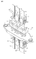
- FIG. 2 is a perspective view of the terminal block.
- FIG. 3 is a perspective view for explaining the relay terminal.
- FIG. 4 is an enlarged perspective view showing a part of the terminal block.
- FIG. 5 is a plan view for explaining the current sensor.
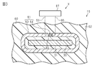
- FIG. 6 is an enlarged cross-sectional view showing a part of the current sensor.
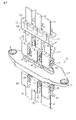
- FIG. 7 is a perspective view showing the terminal block of the second embodiment.
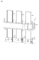
- FIG. 8 is a perspective view showing the terminal block of the third embodiment.
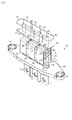
- FIG. 9 is a perspective view showing the terminal block of the fourth embodiment.
- the terminal block of this disclosure is [1] A terminal block including a first terminal electrically connected to an electrical component and a second terminal electrically connected to the first terminal, wherein the first terminal or the second terminal is provided. Is integrated with a current sensor that detects the current flowing through the first terminal or the second terminal.
- the electrical component it is not necessary for the electrical component to be equipped with the current sensor. Therefore, for example, as in the case where the electrical component is equipped with the current sensor, the electrical component is provided with the current sensor. Will not become large. Therefore, it can contribute to the miniaturization of electrical components.
- One of the first terminal and the second terminal may have a clip portion, and the other of the first terminal and the second terminal may be a flat plate-shaped bus bar sandwiched between the clip portions. ..
- the first terminal and the second terminal can be connected only by sandwiching the bus bar with the clip portion. Therefore, for example, a component for connecting the first terminal and the second terminal is separately provided. There is no need to prepare, and the terminal block itself can be miniaturized. Further, the first terminal and the second terminal can be easily electrically connected while absorbing the dimensional tolerances of the first terminal and the second terminal.
- the second terminal may have the clip portion, and the first terminal may be the bus bar.
- the configuration of the first terminal can be simplified. Therefore, for example, the configuration of the first terminal becomes complicated, and the design of the parts existing around the first terminal is changed. You can avoid the problem of having to do it.
- the bus bar may have a flat plate portion surrounded by the current sensor. According to this configuration, since the bus bar has a flat plate portion surrounded by the current sensor, the current sensor can be easily integrated into the first terminal.
- the second terminal may be the bus bar, and the first terminal may have the clip portion. According to this configuration, the configuration of the second terminal can be simplified. Therefore, for example, the configuration of the second terminal becomes complicated, and the design of the parts existing around the second terminal is changed. You can avoid the problem of having to do it.
- the first terminal may have a flat plate portion extending from the clip portion and surrounded by the current sensor. According to this configuration, since the first terminal has a flat plate portion extending from the clip portion and surrounded by the current sensor, the current sensor can be easily integrated into the first terminal.
- the clip portion may have a pair of sandwiching portions for sandwiching the bus bar and an urging member for urging the pair of sandwiching portions in a direction approaching each other.
- the urging member urges the pair of holding portions in the direction of approaching each other, so that the bus bar can be stably held by the pair of holding portions. Therefore, the electrical connection state between the first terminal and the second terminal can be stabilized, and the reliability can be improved.
- a plurality of sets of the first terminal and the second terminal are provided, and the current sensor includes a sensor component provided corresponding to each of the first terminal or each of the second terminals, and a plurality of the sensors. It is preferable to have a base member containing components.
- each sensor component is connected to each first terminal.
- the work of arranging each of them so as to correspond to each second terminal can be facilitated.
- the terminal block of this disclosure is [9] A terminal block including a first terminal electrically connected to an electrical component, a second terminal electrically connected to the first terminal, and a resin housing holding the second terminal.
- the housing is integrated with a current sensor that detects the current flowing through the second terminal.
- the electrical component it is not necessary for the electrical component to be equipped with the current sensor. Therefore, for example, as in the case where the electrical component is equipped with the current sensor, the electrical component is provided with the current sensor. Will not become large. Therefore, it can contribute to the miniaturization of electrical components.
- the terminal block 10 shown in FIG. 1 is mounted on the vehicle V.
- the vehicle V includes a motor 11 and an inverter 12.
- the motor 11 and the inverter 12 are electrical components mounted on the vehicle V.
- the motor 11 is housed in the motor housing 13.
- the inverter 12 has a circuit board 12a.
- the terminal block 10 is attached to the motor housing 13. Specifically, the terminal block 10 is fixed to the motor housing 13 by, for example, a bolt 14.
- the terminal block 10 electrically connects the motor 11 and the circuit board 12a of the inverter 12.
- the terminal block 10 includes a housing 20, an inverter terminal 30, a relay terminal 40, a motor terminal 50, and a current sensor 60.
- the terminal block 10 includes three inverter terminals 30, three relay terminals 40, and three motor terminals 50 corresponding to the U phase, V phase, and W phase of the motor 11. Therefore, the terminal block 10 includes a plurality of sets of an inverter terminal 30, a relay terminal 40, and a motor terminal 50, respectively.
- Each inverter terminal 30 is an elongated thin plate-shaped bus bar.
- the thickness of each inverter terminal 30 is the same.
- the length in the long side direction which is the direction in which the long side of each inverter terminal 30 extends, is the same.
- the width of each inverter terminal 30 is the same.
- the inverter terminals 30 are arranged in a state where the thickness directions of the inverter terminals are the same and the width directions of the inverter terminals are the same.
- the first end portion located on one side in the long side direction of each inverter terminal 30 is electrically connected to the circuit board 12a of the inverter 12. Therefore, each inverter terminal 30 is a first terminal electrically connected to the inverter 12, which is an electrical component.
- the second end of each inverter terminal 30 located on the other side in the long side direction is electrically connected to the relay terminal 40.
- Each inverter terminal 30 has a flat plate portion 31 surrounded by a current sensor 60.
- the flat plate portion 31 of each inverter terminal 30 penetrates the inside of the current sensor 60.
- a current sensor 60 is integrated with each inverter terminal 30.
- Each motor terminal 50 is an elongated thin plate-shaped bus bar.
- the thickness of each motor terminal 50 is the same.
- the length in the long side direction which is the direction in which the long side of each motor terminal 50 extends, is the same.
- the width direction the width of each motor terminal 50 is the same.
- the motor terminals 50 are arranged in a state where their thickness directions coincide with each other and their width directions coincide with each other.
- the first end located on one side of each motor terminal 50 in the long side direction is electrically connected to each motor wiring 11a drawn from each of the U-phase coil, the V-phase coil, and the W-phase coil of the motor 11. There is.
- each motor terminal 50 and each motor wiring 11a are connected to each other via a connection terminal (not shown).
- Each motor terminal 50 is electrically connected to the motor 11 via each motor wiring 11a. Therefore, each motor terminal 50 is a first terminal electrically connected to the motor 11 which is an electrical component.
- each motor wiring 11a is schematically shown. The second end of each motor terminal 50 located on the other side in the long side direction is electrically connected to the relay terminal 40.
- each relay terminal 40 has a first clip portion 41 and a second clip portion 42, which are clip portions, and a connection portion 43, respectively.
- the first clip portion 41 sandwiches the second end portion of the inverter terminal 30.
- the relay terminal 40 is electrically connected to the inverter terminal 30 by the first clip portion 41 sandwiching the inverter terminal 30.
- the second clip portion 42 sandwiches the second end portion of the motor terminal 50.
- the relay terminal 40 is electrically connected to the motor terminal 50 by the second clip portion 42 sandwiching the motor terminal 50. Therefore, the relay terminal 40 is a second terminal electrically connected to the inverter terminal 30 and the motor terminal 50, which are the first terminals, respectively.
- connection portion 43 connects the first clip portion 41 and the second clip portion 42.
- the connecting portion 43 has an elongated plate shape.
- the first clip portion 41 is continuous with the first end portion located on one side in the long side direction in which the long side of the connecting portion 43 extends.
- the second clip portion 42 is continuous with the second end portion located on the other side in the long side direction of the connecting portion 43.
- the first clip portion 41 has a pair of base portions 44, a pair of extending portions 45, a pair of bent portions 46, and a pair of holding portions 47.
- Each base portion 44 has a thin plate shape extending in a direction away from the first end portion of the connecting portion 43.
- Each base portion 44 of the second clip portion 42 extends in a direction away from the second end portion of the connecting portion 43. The extending direction of each base 44 from the connecting portion 43 coincides with the thickness direction of the connecting portion 43.
- Each extending portion 45 has an elongated thin plate shape extending in the thickness direction of each base portion 44 from an end portion of each base portion 44 opposite to the connecting portion 43. The length of each extending portion 45 is the same. Each extending portion 45 extends parallel to each other. Each bent portion 46 is continuous with an end portion of each extended portion 45 opposite to the base portion 44. Each bent portion 46 has a curved plate shape that curves in an arc shape. Each bent portion 46 is curved in a direction approaching each other from each extended portion 45.
- Each sandwiching portion 47 is in the shape of an elongated thin plate extending from an end portion of each bent portion 46 opposite to the extending portion 45 toward each base portion 44. Each sandwiching portion 47 gradually separates from each extending portion 45 as it separates from each bent portion 46. Therefore, each sandwiching portion 47 extends diagonally so as to intersect the extending direction of each extending portion 45. The tip of each sandwiching portion 47 is separated from each base portion 44.
- the pair of sandwiching portions 47 of the first clip portion 41 sandwich the inverter terminal 30 which is a bus bar.
- the pair of holding portions 47 of the second clip portion 42 sandwich the motor terminal 50, which is a bus bar.
- the first clip portion 41 and the second clip portion 42 each have an urging member 48.
- the urging member 48 has a connecting portion 48a and a pair of urging portions 48b.
- the connecting portion 48a has a long thin plate shape.
- Each urging portion 48b has a thin plate shape extending from both end edges located in the short side direction of the connecting portion 48a.
- Each urging portion 48b extends diagonally from each of both end edges of the connecting portion 48a so as to intersect the extending direction of the connecting portion 48a.
- Each urging portion 48b extends in a direction approaching each other as it separates from the connecting portion 48a.
- the urging member 48 is attached to the tip of a pair of holding portions 47.
- the pair of holding portions 47 are arranged between the pair of urging portions 48b.
- the respective urging portions 48b are separated from each other with the end portion of each urging portion 48b on the connecting portion 48a side as a base point. Each is displaced. Then, each urging portion 48b tries to return to the original position before being displaced in the direction away from each other, so that each urging portion 48b urges each holding portion 47.
- the inverter terminals 30 are arranged between the pair of holding portions 47 because, for example, the pair of holding portions 47 of the first clip portion 41 are urged in the direction of approaching each other by each biasing portion 48b. Then, the inverter terminals 30 are stably sandwiched by the pair of sandwiching portions 47. Further, for example, since the pair of holding portions 47 of the second clip portion 42 are urged by each urging portion 48b in a direction in which the pair of holding portions 47 approach each other, the motor terminal 50 is arranged between the pair of holding portions 47. The motor terminal 50 is stably sandwiched by the pair of sandwiching portions 47. Therefore, the urging member 48 urges the pair of holding portions 47 in the direction of approaching each other.
- the housing 20 is made of resin.
- the housing 20 has a plate shape.
- the housing 20 has a bolt insertion hole 21 into which a bolt 14 can be inserted.
- the housing 20 holds each relay terminal 40.
- the housing 20 holds a part of the connection portion 43 of each relay terminal 40.
- Each relay terminal 40 and the housing 20 are integrated by insert molding.
- the current sensor 60 is integrated with the flat plate portion 31 of each inverter terminal 30.
- the current sensor 60 has a sensor component 61 provided corresponding to each inverter terminal 30, and a base member 62 containing a plurality of sensor components 61.
- the base member 62 is made of resin.
- the base member 62 has a long square block shape. The direction in which the long side of the base member 62 extends coincides with the width direction of each inverter terminal 30.
- the base member 62 surrounds the flat plate portion 31 of each inverter terminal 30.
- each sensor component 61 has a core member 63 and a Hall element 64, respectively.
- Each core member 63 is a C-type ferrite core. Therefore, a gap 65 is formed in a part of each core member 63.
- Each core member 63 is arranged so as to surround the flat plate portion 31 of each inverter terminal 30.
- Each Hall element 64 is arranged in the gap 65 of each core member 63.
- Each Hall element 64 is electrically connected to the vehicle ECU 67 via each wiring 66.
- the base member 62, the flat plate portion 31 of each inverter terminal 30, each core member 63, and each Hall element 64 are integrated by insert molding.
- the current flowing from the circuit board 12a of the inverter 12 to each inverter terminal 30 is supplied to the motor 11 via each relay terminal 40, each motor terminal 50, and each motor wiring 11a.
- a current flows from the circuit board 12a of the inverter 12 to each inverter terminal 30 a magnetic flux is generated in each core member 63, and the magnetic flux generated in each core member 63 passes through each Hall element 64.
- a Hall voltage based on the magnetic flux is generated in each Hall element 64.
- the Hall voltage is proportional to the value of the current flowing through each inverter terminal 30. Therefore, it can be said that the current sensor 60 detects the current flowing through each inverter terminal 30.
- the signal related to the Hall voltage generated by each Hall element 64 is output to the vehicle ECU 67 via the wiring 66.
- the vehicle ECU 67 controls the drive of the inverter 12 so that the current value supplied from the inverter 12 to the motor 11 becomes a desired current value based on the signal output from each Hall element 64. Then, when the current value supplied from the inverter 12 to the motor 11 becomes a desired current value, the motor 11 rotates at a desired rotation speed. Therefore, by detecting the current flowing through each inverter terminal 30 by the current sensor 60, the drive of the inverter 12 is controlled, and as a result, the drive of the motor 11 is controlled.
- the inverter terminal 30 is integrated with a current sensor 60 that detects the current flowing through the inverter terminal 30. According to this configuration, it is not necessary for the inverter 12 to be provided with the current sensor 60. Therefore, as in the case where the inverter 12 is provided with the current sensor 60, for example, only the amount provided with the current sensor 60 is provided. , The inverter 12 does not become large. Therefore, it can contribute to the miniaturization of the inverter 12.
- the relay terminal 40 has a first clip portion 41 and a second clip portion 42.
- the inverter terminal 30 is a flat plate-shaped bus bar sandwiched between the first clip portions 41
- the motor terminal 50 is a flat plate-shaped bus bar sandwiched between the second clip portions 42.
- the inverter terminal 30 and the relay terminal 40 can be connected only by sandwiching the inverter terminal 30 by the first clip portion 41. Therefore, for example, the inverter terminal 30 and the relay terminal 40 are connected. It is not necessary to separately prepare parts for this purpose, and the terminal block 10 itself can be miniaturized. Further, the inverter terminal 30 and the relay terminal 40 can be easily electrically connected while absorbing the dimensional tolerances of the inverter terminal 30 and the relay terminal 40.
- the motor terminal 50 and the relay terminal 40 can be connected only by sandwiching the motor terminal 50 by the second clip portion 42, for example, a component for connecting the motor terminal 50 and the relay terminal 40 may be provided.
- the terminal block 10 itself can be miniaturized without the need to prepare it separately. Further, the motor terminal 50 and the relay terminal 40 can be easily electrically connected while absorbing the dimensional tolerances of the motor terminal 50 and the relay terminal 40.
- the relay terminal 40 has a first clip portion 41 and a second clip portion 42.
- the inverter terminal 30 and the motor terminal 50 are bus bars. According to this configuration, the configuration of the inverter terminal 30 and the motor terminal 50 can be simplified. Therefore, for example, the configuration of the inverter terminal 30 and the motor terminal 50 becomes complicated, so that the inverter terminal 30 and the motor terminal are configured. It is possible to avoid the problem that the design of the parts existing around each of the 50 parts must be changed.
- the inverter terminal 30 has a flat plate portion 31 surrounded by the current sensor 60. According to this configuration, since the inverter terminal 30 has a flat plate portion 31 surrounded by the current sensor 60, the current sensor 60 can be easily integrated with the inverter terminal 30.
- the first clip portion 41 has a pair of sandwiching portions 47 that sandwich the inverter terminal 30, and an urging member 48 that urges the pair of sandwiching portions 47 in a direction approaching each other. ..
- the urging member 48 urges the pair of holding portions 47 in the direction of approaching each other, so that the pair of holding portions 47 stably sandwich the inverter terminal 30. be able to. Therefore, the electrical connection state between the inverter terminal 30 and the relay terminal 40 can be stabilized, and the reliability can be improved.
- the second clip portion 42 has a pair of holding portions 47 for sandwiching the motor terminal 50, and an urging member 48 for urging the pair of sandwiching portions 47 in a direction approaching each other.
- the urging member 48 urges the pair of holding portions 47 in the direction of approaching each other, so that the pair of holding portions 47 stably hold the motor terminal 50. be able to. Therefore, the electrical connection state between the motor terminal 50 and the relay terminal 40 can be stabilized, and the reliability can be improved.
- the current sensor 60 has a sensor component 61 provided corresponding to each inverter terminal 30, and a base member 62 containing a plurality of sensor components 61. According to this configuration, since the current sensor 60 has a base member 62 containing each sensor component 61 provided corresponding to each inverter terminal 30, each sensor component 61 is attached to each inverter terminal 30. The work of arranging each correspondingly can be facilitated.
- each relay terminal 70 is an elongated thin plate-shaped bus bar.
- the thickness of each relay terminal 70 is the same.
- the length in the long side direction which is the direction in which the long side of each relay terminal 70 extends, is the same.
- the width of each relay terminal 70 is the same.
- the relay terminals 70 are arranged in a state where their thickness directions are the same and their width directions are the same.
- the first end located on one side in the long side direction of each relay terminal 70 is electrically connected to each inverter terminal 80. Therefore, the relay terminal 70 is a second terminal electrically connected to the inverter terminal 80, which is the first terminal.
- the second end of each relay terminal 70 located on the other side in the long side direction is electrically connected to each motor terminal (not shown).
- Each inverter terminal 80 is a first terminal electrically connected to an inverter 12 which is an electrical component.
- Each inverter terminal 80 has a clip portion 81 and a flat plate portion 82 extending from the clip portion 81, respectively. Since the configuration of the clip portion 81 is the same as the configuration of the first clip portion 41 and the second clip portion 42 described in the first embodiment, the same reference numerals are given and detailed description thereof will be omitted. ..
- the clip portion 81 sandwiches the first end portion of the relay terminal 70.
- the inverter terminal 80 is electrically connected to the relay terminal 70 by the clip portion 81 sandwiching the first end portion of the relay terminal 70.
- the flat plate portion 82 has an elongated thin plate shape extending from the clip portion 81.
- the flat plate portion 82 of each inverter terminal 80 is surrounded by the current sensor 60.
- the flat plate portion 82 of each inverter terminal 80 penetrates the inside of the current sensor 60.
- a current sensor 60 is integrated with each inverter terminal 80.
- one of the inverter terminals 30, 80 and the relay terminals 40, 70 has a clip portion, and the other of the inverter terminals 30, 80 and the relay terminals 40, 70 has a clip portion.
- a flat plate-shaped bus bar sandwiched between clips may be used.
- the inverter terminal 80 has a clip portion 81.
- the relay terminal 70 is a flat plate-shaped bus bar sandwiched between the clip portions 81. According to this configuration, the inverter terminal 80 and the relay terminal 70 can be connected only by sandwiching the relay terminal 70 by the clip portion 81. Therefore, for example, for connecting the inverter terminal 80 and the relay terminal 70.
- the terminal block 10 itself can be miniaturized without the need to prepare parts separately. Further, the inverter terminal 80 and the relay terminal 70 can be easily electrically connected while absorbing the dimensional tolerances of the inverter terminal 80 and the relay terminal 70.
- the relay terminal 70 is a bus bar, and the inverter terminal 80 has a clip portion 81. According to this configuration, the configuration of the relay terminal 70 can be simplified. Therefore, for example, the configuration of the relay terminal 70 becomes complicated, and the design of the parts existing around the relay terminal 70 is changed. You can avoid the problem of having to do it.
- the inverter terminal 80 has a flat plate portion 82 extending from the clip portion 81 and surrounded by the current sensor 60. According to this configuration, since the inverter terminal 80 extends from the clip portion 81 and has a flat plate portion 82 surrounded by the current sensor 60, the current sensor 60 can be easily integrated with the inverter terminal 80.
- the current sensor 60 is integrated with the connection portion 43 of each relay terminal 40.
- the protrusion length of each relay terminal 40 from the housing 20 at the connection portion 43 differs between the protrusion length of the portion on the first clip portion 41 side and the protrusion length of the portion on the second clip portion 42 side.
- the protruding length of the portion of the connecting portion 43 on the side of the first clip portion 41 from the housing 20 is longer than the protruding length of the portion of the connecting portion 43 on the side of the second clip portion 42 from the housing 20. ing.
- the current sensor 60 is integrated into a portion of the connection portion 43 of each relay terminal 40 located between the housing 20 and the first clip portion 41.
- Each sensor component 61 of the current sensor 60 is provided corresponding to each relay terminal 40.
- the core member 63 of each sensor component 61 is arranged so as to surround the connection portion 43 of each relay terminal 40.
- the base member 62, the connection portion 43 of each relay terminal 40, each core member 63, and each Hall element 64 are integrated by insert molding.
- the current flowing through the inverter terminals 30, 80 or the relay terminals 40, 70 is detected in the inverter terminals 30, 80 or the relay terminals 40, 70. It suffices if the current sensor 60 to be integrated is integrated.
- the sensor component 61 may be provided corresponding to the respective inverter terminals 30 and 80 or the respective relay terminals 40 and 70.
- the current sensor 60 is integrated in a portion of the connection portion 43 of each relay terminal 40 located between the housing 20 and the first clip portion 41. According to this configuration, it is not necessary to make a design change such as lengthening the inverter terminal 30 in order to secure a space for integrating the current sensor 60, for example, when the current sensor 60 is integrated with the inverter terminal 30. .. Therefore, the configuration of the inverter terminal 30 can be simplified.
- the current sensor 60 is integrated in the housing 20.
- Each sensor component 61 of the current sensor 60 is provided corresponding to each relay terminal 40.
- the core member 63 of each sensor component 61 is arranged so as to surround the connection portion 43 of each relay terminal 40.
- the core member 63 and the Hall element 64 of each sensor component 61 are embedded in the housing 20.
- the housing 20, the connection portion 43 of each relay terminal 40, each core member 63, and each Hall element 64 are integrated by insert molding.
- the current sensor 60 is integrated with the housing 20. According to this configuration, in order to secure a space for integrating the current sensor 60, for example, when the current sensor 60 is integrated with the inverter terminal 30 or the current sensor 60 is integrated with the relay terminal 40. It is not necessary to change the design such as lengthening the connection portion 43 of the inverter terminal 30 and the relay terminal 40. Therefore, the configuration of the inverter terminal 30 and the relay terminal 40 can be simplified.
- the current sensor 60 may not be integrated into each inverter terminal 30, and the current sensor 60 may be integrated into each motor terminal 50, for example.
- each motor terminal 50 has a flat plate portion surrounded by the current sensor 60.
- the motor 11 does not need to include the current sensor 60 even if the current sensor 60 is housed in the motor housing 13. Therefore, for example, as in the case where the motor 11 is provided with the current sensor 60, the size of the motor 11 is not increased by the amount provided with the current sensor 60. Therefore, it can contribute to the miniaturization of the motor 11.
- the current sensor 60 is not integrated in the portion located between the housing 20 and the first clip portion 41 in the connection portion 43 of each relay terminal 40, but in each relay terminal 40. It may be integrated in a portion located between the housing 20 and the second clip portion 42 in the connection portion 43 of the above. In this case, the protruding length of the portion of the connecting portion 43 on the side of the second clip portion 42 from the housing 20 is longer than the protruding length of the portion of the connecting portion 43 on the side of the first clip portion 41 from the housing 20. ..
- the specific configuration of the first clip portion 41, the second clip portion 42, or the clip portion 81 is not particularly limited.
- the motor terminal 50, or the relay terminal 70, which is a bus bar by the pair of sandwiching portions 47 themselves, the first clip portion 41, the second clip portion 42, or the clip portion.
- the 81 may have a configuration in which the urging member 48 is omitted.
- each sensor component 61 of the current sensor 60 is not particularly limited.
- Each sensor component 61 may have a configuration in which a winding is wound around an annular core member, for example, without using the Hall element 64.
- the numbers of the inverter terminals 30, 80, the relay terminals 40, 70, and the motor terminals 50 are the same as those of the inverter terminals 30, 80, the relay terminals 40, 70, and the motor terminals 50, respectively. However, it is not particularly limited.
- the terminal block 10 electrically connects the motor 11 and the inverter 12, but the terminal block 10 is not limited to this, and electrical components other than the motor 11 and the inverter 12 are electrically connected to each other. It may be something to do.
- electricity including first and second electrical component terminals, which may be inverter terminals 30 and motor terminals 50, and a relay terminal 40 of a terminal block 10 between the first and second electrical component terminals.
- the path may be referred to as an electrical component conduction structure.
- the terminal block 10 is configured such that the inverter terminal 30 and the motor terminal 50 are electrically conductive via the relay terminal 40 without the flexible electric wire which may be a wire harness between them. May be done.
- the housing 20 of the terminal block 10 is fixed to the outer surface of a first electrical component, which may be a motor 11, or has a first housing surface facing the outer surface of the first electrical component and an inverter. It may have a second housing surface facing the outer surface of the second electrical component, which may be twelve. As shown in FIG. 1, a gap may be formed between the second housing surface of the housing 20 and the outer surface of the second electrical component which may be the inverter 12.
- the current sensor 60 may be arranged, for example, in the gap between the second housing surface of the housing 20 and the outer surface of the second electrical component, which may be the inverter 12.
- the two clip portions 41 and 42 of one relay terminal 40 of the terminal block 10 may be free ends of the relay terminal 40.
- the connection portion 43 between the two clip portions 41 and 42 of one relay terminal 40 may be at an intermediate length position of the relay terminal 40.
- the connection portion 43 of the relay terminal 40 may be fixedly held in the housing 20.
- the relay terminal 40 may penetrate the housing 20, for example, linearly.
- One of the two clip portions 41, 42 may project linearly from the first housing surface of the housing 20, and the other of the two clip portions 41, 42 may linearly project from the second housing surface of the housing 20. May protrude into.
- the clip portion 41 may allow limited sliding between the relay terminal 40 and the inverter terminal 30, and the clip portion 42 may allow limited sliding between the relay terminal 40 and the motor terminal 50. .. Clipping of the clip portions 41 and 42 absorbs dimensional tolerances and assembly tolerances in the length direction and / or the width direction and / or the thickness direction between the relay terminal 40, the inverter terminal 30, and the motor terminal 50. It is advantageous for.
- the terminal block 10 includes a housing 20, second terminals 40 and 70 extending vertically and vertically of the housing 20, and second terminals. It may be provided with two first terminals 30, 50, 80, which are connected to both ends of the 40, 70 and extend in the same direction as the second terminals 40, 70, respectively.
- the electrical components 11 and 12 and the first terminals 30, 50 and 80 may be electrically connected to each other.
- the first terminals 30, 50, 80 and the second terminals 40, 70 may also be electrically connected.
- a current sensor 60 for detecting the current flowing through the first terminal 30, 50, 80 or the second terminal 40, 70 is integrated in the housing 20, the first terminal 30, 50, 80, or the second terminal 40, 70. It's okay.
- the direction in which the current sensor 60 extends may coincide with the direction in which the housing 20 extends.
- Terminal block 11 Motor (electrical components) 11a Motor wiring 12 Inverter (electrical components) 12a Circuit board 13 Motor housing 14 Bolt 20 Housing 21 Bolt insertion hole 30 Inverter terminal (1st terminal, bus bar) 31 Flat plate 40 Relay terminal (second terminal) 41 First clip part (clip part) 42 Second clip part (clip part) 43 Connection part 44 Base part 45 Extension part 46 Bending part 47 Holding part 48 Bias member 48a Connecting part 48b Bounce part 50 Motor terminal (1st terminal) 60 Current sensor 61 Sensor parts 63 Core parts 64 Hall elements 65 Gap 66 Wiring 67 Vehicle ECU 70 Relay terminal (2nd terminal, bus bar) 80 Inverter terminal (1st terminal) 81 Clip part 82 Flat part V Vehicle
Landscapes
- Engineering & Computer Science (AREA)
- Power Engineering (AREA)
- Microelectronics & Electronic Packaging (AREA)
- Physics & Mathematics (AREA)
- General Physics & Mathematics (AREA)
- Connections Arranged To Contact A Plurality Of Conductors (AREA)
- Measuring Instrument Details And Bridges, And Automatic Balancing Devices (AREA)
Abstract
Description
本開示の目的は、電装品の小型化に貢献することができる端子台を提供することにある。
最初に本開示の実施形態を列記して説明する。
本開示の端子台は、
[1]電装品に電気的に接続される第1端子と、前記第1端子に電気的に接続される第2端子と、を備える端子台であって、前記第1端子又は前記第2端子には、前記第1端子又は前記第2端子を流れる電流を検出する電流センサが一体化されている。
この構成によれば、クリップ部によってバスバーを挟持するだけで、第1端子と第2端子とを接続することができるため、例えば、第1端子と第2端子とを接続するための部品を別途用意する必要が無く、端子台自体を小型化することができる。さらには、第1端子及び第2端子それぞれの寸法公差を吸収しつつも、第1端子と第2端子とを容易に電気的に接続することができる。
この構成によれば、第1端子の構成を簡素な構成にすることができるため、例えば、第1端子の構成が複雑化することによって、第1端子の周囲に存在する部品の設計を変更しなければならなくなってしまうといった問題を回避することができる。
この構成によれば、バスバーが、電流センサに取り囲まれる平板部を有しているため、第1端子に電流センサを容易に一体化することができる。
この構成によれば、第2端子の構成を簡素な構成にすることができるため、例えば、第2端子の構成が複雑化することによって、第2端子の周囲に存在する部品の設計を変更しなければならなくなってしまうといった問題を回避することができる。
この構成によれば、第1端子が、クリップ部から延びるとともに電流センサに取り囲まれる平板部を有しているため、第1端子に電流センサを容易に一体化することができる。
この構成によれば、付勢部材が一対の挟持部を互いに接近する方向へ付勢することにより、一対の挟持部によってバスバーを安定的に挟持することができる。したがって、第1端子と第2端子との電気的接続状態を安定的なものとすることができるため、信頼性を向上させることができる。
[9]電装品に電気的に接続される第1端子と、前記第1端子に電気的に接続される第2端子と、前記第2端子を保持する樹脂製のハウジングと、を備える端子台であって、前記ハウジングには、前記第2端子を流れる電流を検出する電流センサが一体化されている。
本開示の端子台の具体例を、以下に図面を参照しつつ説明する。なお、本発明はこれらの例示に限定されるものではなく、特許請求の範囲によって示され、特許請求の範囲と均等の意味および範囲内でのすべての変更が含まれることが意図される。また、図面では、説明の便宜上、構成の一部を誇張又は簡略化して示す場合があり、各部分の寸法比率についても、実際と異なる場合がある。さらには、各部分の寸法比率については各図面で異なる場合がある。
以下、端子台の第1実施形態について説明する。
(全体構成)
図1に示す端子台10は、車両Vに搭載されている。車両Vは、モータ11と、インバータ12と、を備えている。モータ11及びインバータ12は、車両Vに搭載される電装品である。モータ11は、モータハウジング13内に収容されている。インバータ12は、回路基板12aを有している。端子台10は、モータハウジング13に取り付けられている。具体的には、端子台10は、例えば、ボルト14によってモータハウジング13に固定されている。そして、端子台10は、モータ11とインバータ12の回路基板12aとを電気的に接続している。
図1及び図2に示すように、端子台10は、ハウジング20と、インバータ端子30と、中継端子40と、モータ端子50と、電流センサ60と、を備えている。端子台10は、モータ11のU相、V相、及びW相に対応して、インバータ端子30、中継端子40、及びモータ端子50をそれぞれ3つずつ備えている。したがって、端子台10は、インバータ端子30、中継端子40、及びモータ端子50をそれぞれ複数組備えている。
各インバータ端子30は、細長薄板平板状のバスバーである。各インバータ端子30の厚みはそれぞれ同じである。各インバータ端子30の長辺が延びる方向である長辺方向の長さはそれぞれ同じである。各インバータ端子30の短辺が延びる方向を幅方向とすると、各インバータ端子30の幅はそれぞれ同じである。各インバータ端子30は、それぞれの厚み方向が一致し、且つそれぞれの幅方向が一致した状態で互いに配置されている。各インバータ端子30の長辺方向の一方に位置する第1端部は、インバータ12の回路基板12aに電気的に接続されている。したがって、各インバータ端子30は、電装品であるインバータ12に電気的に接続される第1端子である。各インバータ端子30の長辺方向の他方に位置する第2端部は、中継端子40に電気的に接続されている。
各モータ端子50は、細長薄板平板状のバスバーである。各モータ端子50の厚みはそれぞれ同じである。各モータ端子50の長辺が延びる方向である長辺方向の長さはそれぞれ同じである。各モータ端子50の短辺が延びる方向を幅方向とすると、各モータ端子50の幅はそれぞれ同じである。各モータ端子50は、それぞれの厚み方向が一致し、且つそれぞれの幅方向が一致した状態で互いに配置されている。各モータ端子50の長辺方向の一方に位置する第1端部は、モータ11のU相コイル、V相コイル、及びW相コイルそれぞれから引き出される各モータ配線11aにそれぞれ電気的に接続されている。なお、各モータ端子50の第1端部と各モータ配線11aとは、図示しない接続端子を介してそれぞれ接続されている。そして、各モータ端子50は、各モータ配線11aを介してモータ11に電気的に接続されている。したがって、各モータ端子50は、電装品であるモータ11に電気的に接続される第1端子である。なお、図1では、各モータ配線11aを模式的に図示している。各モータ端子50の長辺方向の他方に位置する第2端部は、中継端子40に電気的に接続されている。
図3に示すように、各中継端子40は、クリップ部である第1クリップ部41及び第2クリップ部42と、接続部43と、をそれぞれ有している。第1クリップ部41は、インバータ端子30の第2端部を挟持する。そして、中継端子40は、第1クリップ部41がインバータ端子30を挟持することにより、インバータ端子30に電気的に接続されている。第2クリップ部42は、モータ端子50の第2端部を挟持する。そして、中継端子40は、第2クリップ部42がモータ端子50を挟持することにより、モータ端子50に電気的に接続されている。したがって、中継端子40は、第1端子であるインバータ端子30及びモータ端子50にそれぞれ電気的に接続される第2端子である。
第1クリップ部41及び第2クリップ部42の構成は同じであるため、以下の説明では、第1クリップ部41の構成の説明を詳細に説明し、第2クリップ部42の構成の説明は、同一符号を付すなどして簡略化する。
図2に示すように、ハウジング20は、樹脂製である。ハウジング20は、板状である。ハウジング20は、ボルト14が挿通可能なボルト挿通孔21を有している。ハウジング20は、各中継端子40を保持している。具体的には、ハウジング20は、各中継端子40の接続部43の一部分を保持している。各中継端子40とハウジング20とは、インサート成形により一体化されている。
図4及び図5に示すように、電流センサ60は、各インバータ端子30の平板部31に一体化されている。電流センサ60は、それぞれのインバータ端子30に対応して設けられたセンサ部品61と、複数のセンサ部品61を内蔵するベース部材62と、を有している。ベース部材62は、樹脂製である。ベース部材62は、長四角ブロック状である。ベース部材62の長辺が延びる方向は、各インバータ端子30の幅方向に一致している。ベース部材62は、各インバータ端子30の平板部31を取り囲んでいる。
次に、第1実施形態の作用について説明する。
インバータ12の回路基板12aから各インバータ端子30に流れた電流は、各中継端子40、各モータ端子50、及び各モータ配線11aを介してモータ11に供給される。インバータ12の回路基板12aから各インバータ端子30に電流が流れると、各コア部材63に磁束が発生し、各コア部材63で発生した磁束が各ホール素子64を通過する。これにより、各ホール素子64には、磁束に基づいたホール電圧が生じる。ホール電圧は、各インバータ端子30を流れる電流の値に比例している。したがって、電流センサ60は、各インバータ端子30を流れる電流を検出していると言える。
(1-1)インバータ端子30には、インバータ端子30を流れる電流を検出する電流センサ60が一体化されている。この構成によれば、インバータ12が電流センサ60を備えている必要が無いため、例えば、インバータ12が電流センサ60を備えている構成である場合のように、電流センサ60を備えている分だけ、インバータ12が大型化してしまうといったことが無くなる。したがって、インバータ12の小型化に貢献することができる。
次に、端子台の第2実施形態について説明する。なお、以下で説明する実施形態では、第1実施形態との相違点について主に説明し、第1実施形態と同様の構成には同じ符号を付して、説明の一部又は全部を割愛する場合がある。
図7に示すように、各中継端子70は、細長薄板平板状のバスバーである。各中継端子70の厚みはそれぞれ同じである。各中継端子70の長辺が延びる方向である長辺方向の長さはそれぞれ同じである。各中継端子70の短辺が延びる方向を幅方向とすると、各中継端子70の幅はそれぞれ同じである。各中継端子70は、それぞれの厚み方向が一致し、且つそれぞれの幅方向が一致した状態で互いに配置されている。各中継端子70の長辺方向の一方に位置する第1端部は、各インバータ端子80に電気的に接続されている。したがって、中継端子70は、第1端子であるインバータ端子80に電気的に接続される第2端子である。なお、各中継端子70の長辺方向の他方に位置する第2端部は、図示しない各モータ端子に電気的に接続されている。
各インバータ端子80は、電装品であるインバータ12に電気的に接続される第1端子である。各インバータ端子80は、クリップ部81と、クリップ部81から延びる平板部82と、をそれぞれ有している。なお、クリップ部81の構成は、第1実施形態で説明した第1クリップ部41及び第2クリップ部42の構成と同じであるため、同一符号を付すなどして、その詳細な説明を省略する。
第2実施形態では、第1実施形態の効果(1-1)、(1-5)、及び(1-6)と同様な効果に加えて、以下の効果を得ることができる。
次に、端子台の第3実施形態について説明する。
図8に示すように、電流センサ60は、各中継端子40の接続部43に一体化されている。各中継端子40の接続部43におけるハウジング20からの突出長さは、第1クリップ部41側の部分の突出長さと第2クリップ部42側の部分の突出長さとで異なっている。具体的には、接続部43における第1クリップ部41側の部分のハウジング20からの突出長さは、接続部43における第2クリップ部42側の部分のハウジング20からの突出長さよりも長くなっている。そして、電流センサ60は、各中継端子40の接続部43におけるハウジング20と第1クリップ部41との間に位置する部位に一体化されている。
第3実施形態では、第1実施形態の効果(1-1)、(1-2)、(1-3)、(1-5)、及び(1-6)と同様な効果に加えて、以下の効果を得ることができる。
次に、端子台の第4実施形態について説明する。
図9に示すように、ハウジング20には、電流センサ60が一体化されている。電流センサ60の各センサ部品61は、それぞれの中継端子40に対応して設けられている。各センサ部品61のコア部材63は、各中継端子40の接続部43を取り囲むようにそれぞれ配置されている。各センサ部品61のコア部材63及びホール素子64は、ハウジング20内に埋設されている。ハウジング20と、各中継端子40の接続部43と、各コア部材63と、各ホール素子64とは、インサート成形により一体化されている。
第4実施形態では、第1実施形態の効果(1-1)、(1-2)、(1-3)、(1-5)、及び(1-6)と同様な効果に加えて、以下の効果を得ることができる。
なお、上記各実施形態は、以下のように変更して実施することができる。上記各実施形態及び以下の変更例は、技術的に矛盾しない範囲で互いに組み合わせて実施することができる。
電装品11,12と第1端子30,50,80とは電気的に接続されてよく、
第1端子30,50,80と第2端子40,70とも電気的に接続されてよく、
ハウジング20、第1端子30,50,80、又は第2端子40,70には、第1端子30,50,80又は第2端子40,70を流れる電流を検出する電流センサ60が一体化されてよい。
11 モータ(電装品)
11a モータ配線
12 インバータ(電装品)
12a 回路基板
13 モータハウジング
14 ボルト
20 ハウジング
21 ボルト挿通孔
30 インバータ端子(第1端子、バスバー)
31 平板部
40 中継端子(第2端子)
41 第1クリップ部(クリップ部)
42 第2クリップ部(クリップ部)
43 接続部
44 基部
45 延在部
46 屈曲部
47 挟持部
48 付勢部材
48a 連結部
48b 付勢部
50 モータ端子(第1端子)
60 電流センサ
61 センサ部品
62 ベース部材
63 コア部材
64 ホール素子
65 ギャップ
66 配線
67 車両ECU
70 中継端子(第2端子、バスバー)
80 インバータ端子(第1端子)
81 クリップ部
82 平板部
V 車両
Claims (9)
- 電装品に電気的に接続される第1端子と、
前記第1端子に電気的に接続される第2端子と、を備える端子台であって、
前記第1端子又は前記第2端子には、前記第1端子又は前記第2端子を流れる電流を検出する電流センサが一体化されている、
端子台。 - 前記第1端子及び前記第2端子の一方は、クリップ部を有し、
前記第1端子及び前記第2端子の他方は、前記クリップ部に挟持される平板状のバスバーである、
請求項1に記載の端子台。 - 前記第2端子は、前記クリップ部を有し、
前記第1端子は、前記バスバーである、
請求項2に記載の端子台。 - 前記バスバーは、前記電流センサに取り囲まれる平板部を有している、
請求項2又は請求項3に記載の端子台。 - 前記第2端子は、前記バスバーであり、
前記第1端子は、前記クリップ部を有する、
請求項2に記載の端子台。 - 前記第1端子は、前記クリップ部から延びるとともに前記電流センサに取り囲まれる平板部を有している、
請求項5に記載の端子台。 - 前記クリップ部は、前記バスバーを挟持する一対の挟持部と、前記一対の挟持部を互いに接近する方向へ付勢する付勢部材と、を有している、
請求項2から請求項6のいずれか1項に記載の端子台。 - 前記第1端子及び前記第2端子を複数組備え、
前記電流センサは、それぞれの前記第1端子又はそれぞれの前記第2端子に対応して設けられたセンサ部品と、複数の前記センサ部品を内蔵するベース部材と、を有する、
請求項1から請求項7のいずれか1項に記載の端子台。 - 電装品に電気的に接続される第1端子と、
前記第1端子に電気的に接続される第2端子と、
前記第2端子を保持する樹脂製のハウジングと、を備える端子台であって、
前記ハウジングには、前記第2端子を流れる電流を検出する電流センサが一体化されている、
端子台。
Priority Applications (2)
| Application Number | Priority Date | Filing Date | Title |
|---|---|---|---|
| US18/267,541 US20240039184A1 (en) | 2020-12-21 | 2021-11-30 | Terminal block |
| CN202180081151.2A CN116547870A (zh) | 2020-12-21 | 2021-11-30 | 端子座 |
Applications Claiming Priority (2)
| Application Number | Priority Date | Filing Date | Title |
|---|---|---|---|
| JP2020-211820 | 2020-12-21 | ||
| JP2020211820A JP7501346B2 (ja) | 2020-12-21 | 2020-12-21 | 端子台 |
Publications (1)
| Publication Number | Publication Date |
|---|---|
| WO2022138014A1 true WO2022138014A1 (ja) | 2022-06-30 |
Family
ID=82157664
Family Applications (1)
| Application Number | Title | Priority Date | Filing Date |
|---|---|---|---|
| PCT/JP2021/043819 Ceased WO2022138014A1 (ja) | 2020-12-21 | 2021-11-30 | 端子台 |
Country Status (4)
| Country | Link |
|---|---|
| US (1) | US20240039184A1 (ja) |
| JP (1) | JP7501346B2 (ja) |
| CN (1) | CN116547870A (ja) |
| WO (1) | WO2022138014A1 (ja) |
Cited By (1)
| Publication number | Priority date | Publication date | Assignee | Title |
|---|---|---|---|---|
| WO2024029319A1 (ja) * | 2022-08-01 | 2024-02-08 | 株式会社オートネットワーク技術研究所 | 端子台 |
Citations (4)
| Publication number | Priority date | Publication date | Assignee | Title |
|---|---|---|---|---|
| JP2013027203A (ja) * | 2011-07-22 | 2013-02-04 | Hitachi Automotive Systems Ltd | 電力変換装置 |
| JP2013170984A (ja) * | 2012-02-22 | 2013-09-02 | Sumitomo Electric Ind Ltd | 自動車用電流センサ組込み中継バスバー装置 |
| JP2015122250A (ja) * | 2013-12-25 | 2015-07-02 | 株式会社オートネットワーク技術研究所 | 導電部材 |
| JP2018200823A (ja) * | 2017-05-29 | 2018-12-20 | 矢崎総業株式会社 | コネクタ装置 |
Family Cites Families (3)
| Publication number | Priority date | Publication date | Assignee | Title |
|---|---|---|---|---|
| JP5524540B2 (ja) * | 2009-09-01 | 2014-06-18 | 株式会社東海理化電機製作所 | 電流センサ |
| JP5641292B2 (ja) * | 2010-05-19 | 2014-12-17 | 株式会社オートネットワーク技術研究所 | 電流センサ |
| JP5727782B2 (ja) * | 2010-12-28 | 2015-06-03 | 矢崎総業株式会社 | シーソー式スイッチ |
-
2020
- 2020-12-21 JP JP2020211820A patent/JP7501346B2/ja active Active
-
2021
- 2021-11-30 WO PCT/JP2021/043819 patent/WO2022138014A1/ja not_active Ceased
- 2021-11-30 CN CN202180081151.2A patent/CN116547870A/zh active Pending
- 2021-11-30 US US18/267,541 patent/US20240039184A1/en active Pending
Patent Citations (4)
| Publication number | Priority date | Publication date | Assignee | Title |
|---|---|---|---|---|
| JP2013027203A (ja) * | 2011-07-22 | 2013-02-04 | Hitachi Automotive Systems Ltd | 電力変換装置 |
| JP2013170984A (ja) * | 2012-02-22 | 2013-09-02 | Sumitomo Electric Ind Ltd | 自動車用電流センサ組込み中継バスバー装置 |
| JP2015122250A (ja) * | 2013-12-25 | 2015-07-02 | 株式会社オートネットワーク技術研究所 | 導電部材 |
| JP2018200823A (ja) * | 2017-05-29 | 2018-12-20 | 矢崎総業株式会社 | コネクタ装置 |
Cited By (1)
| Publication number | Priority date | Publication date | Assignee | Title |
|---|---|---|---|---|
| WO2024029319A1 (ja) * | 2022-08-01 | 2024-02-08 | 株式会社オートネットワーク技術研究所 | 端子台 |
Also Published As
| Publication number | Publication date |
|---|---|
| JP2022098336A (ja) | 2022-07-01 |
| CN116547870A (zh) | 2023-08-04 |
| JP7501346B2 (ja) | 2024-06-18 |
| US20240039184A1 (en) | 2024-02-01 |
Similar Documents
| Publication | Publication Date | Title |
|---|---|---|
| US9197048B2 (en) | High-voltage electrical junction box | |
| US6707183B2 (en) | Connector with flux concentrator for electric motor and corresponding geared motor | |
| JP4855239B2 (ja) | モータ用絶縁ハウジング | |
| CN101932488B (zh) | 电动式动力转向装置 | |
| US10770955B2 (en) | Connection terminal assembly and electromotive drive device using same | |
| US20170104281A1 (en) | Terminal block connection structure in rotary electric machine | |
| CN105264748B (zh) | 电动助力用马达装置的供电部结构 | |
| US8952688B2 (en) | Current Detector | |
| US20140225593A1 (en) | Current detection device | |
| CN101606304A (zh) | 电动机的端子构造 | |
| CN108735459B (zh) | 噪声滤波器和降噪单元 | |
| CN112816755B (zh) | 电子部件的固定结构和电流检测装置 | |
| JP6615155B2 (ja) | ノイズ低減ユニット | |
| WO2022138014A1 (ja) | 端子台 | |
| JP2011227000A (ja) | 配線材の接続構造 | |
| CN110365227B (zh) | 电力转换装置 | |
| JP5644223B2 (ja) | 電気接続箱 | |
| JP2017075920A (ja) | 部品固定構造及びトルクセンサ | |
| JP4705415B2 (ja) | 電動モータ | |
| JP5531565B2 (ja) | 電気接続箱及び電気接続箱の製造方法 | |
| JP2002299856A (ja) | 自動車のためのインストルメントパネル | |
| JP6889643B2 (ja) | 電子部品内蔵ユニット | |
| JPH06197505A (ja) | 電動機 | |
| JP3888091B2 (ja) | ジャンクションブロック | |
| JP2005337722A (ja) | 電流検出装置、車両用電流検出装置及びコイル |
Legal Events
| Date | Code | Title | Description |
|---|---|---|---|
| 121 | Ep: the epo has been informed by wipo that ep was designated in this application |
Ref document number: 21910166 Country of ref document: EP Kind code of ref document: A1 |
|
| WWE | Wipo information: entry into national phase |
Ref document number: 202180081151.2 Country of ref document: CN |
|
| WWE | Wipo information: entry into national phase |
Ref document number: 18267541 Country of ref document: US |
|
| NENP | Non-entry into the national phase |
Ref country code: DE |
|
| 122 | Ep: pct application non-entry in european phase |
Ref document number: 21910166 Country of ref document: EP Kind code of ref document: A1 |