WO2022137513A1 - 情報処理装置、特定方法、および特定プログラム - Google Patents
情報処理装置、特定方法、および特定プログラム Download PDFInfo
- Publication number
- WO2022137513A1 WO2022137513A1 PCT/JP2020/048768 JP2020048768W WO2022137513A1 WO 2022137513 A1 WO2022137513 A1 WO 2022137513A1 JP 2020048768 W JP2020048768 W JP 2020048768W WO 2022137513 A1 WO2022137513 A1 WO 2022137513A1
- Authority
- WO
- WIPO (PCT)
- Prior art keywords
- objects
- processing
- work
- devices
- information
- Prior art date
Links
- 238000000034 method Methods 0.000 title claims abstract description 65
- 230000010365 information processing Effects 0.000 title claims description 18
- 230000008569 process Effects 0.000 claims abstract description 53
- 238000004088 simulation Methods 0.000 claims abstract description 19
- 230000003247 decreasing effect Effects 0.000 claims description 8
- 238000004422 calculation algorithm Methods 0.000 claims description 5
- 238000009826 distribution Methods 0.000 claims description 4
- 238000004519 manufacturing process Methods 0.000 description 183
- 238000003860 storage Methods 0.000 description 23
- 238000010586 diagram Methods 0.000 description 16
- 238000005457 optimization Methods 0.000 description 16
- 238000004364 calculation method Methods 0.000 description 9
- 230000006870 function Effects 0.000 description 9
- 238000005553 drilling Methods 0.000 description 4
- 230000001186 cumulative effect Effects 0.000 description 3
- 208000018910 keratinopathic ichthyosis Diseases 0.000 description 3
- 230000008859 change Effects 0.000 description 2
- 238000003754 machining Methods 0.000 description 2
- 230000001934 delay Effects 0.000 description 1
- 230000002068 genetic effect Effects 0.000 description 1
- 238000009434 installation Methods 0.000 description 1
- 239000004973 liquid crystal related substance Substances 0.000 description 1
- 238000012986 modification Methods 0.000 description 1
- 230000004048 modification Effects 0.000 description 1
- 239000002994 raw material Substances 0.000 description 1
- 239000007787 solid Substances 0.000 description 1
Images


Classifications
-
- G—PHYSICS
- G06—COMPUTING; CALCULATING OR COUNTING
- G06F—ELECTRIC DIGITAL DATA PROCESSING
- G06F30/00—Computer-aided design [CAD]
- G06F30/20—Design optimisation, verification or simulation
- G06F30/27—Design optimisation, verification or simulation using machine learning, e.g. artificial intelligence, neural networks, support vector machines [SVM] or training a model
-
- G—PHYSICS
- G05—CONTROLLING; REGULATING
- G05B—CONTROL OR REGULATING SYSTEMS IN GENERAL; FUNCTIONAL ELEMENTS OF SUCH SYSTEMS; MONITORING OR TESTING ARRANGEMENTS FOR SUCH SYSTEMS OR ELEMENTS
- G05B19/00—Programme-control systems
- G05B19/02—Programme-control systems electric
- G05B19/418—Total factory control, i.e. centrally controlling a plurality of machines, e.g. direct or distributed numerical control [DNC], flexible manufacturing systems [FMS], integrated manufacturing systems [IMS], computer integrated manufacturing [CIM]
- G05B19/41865—Total factory control, i.e. centrally controlling a plurality of machines, e.g. direct or distributed numerical control [DNC], flexible manufacturing systems [FMS], integrated manufacturing systems [IMS], computer integrated manufacturing [CIM] characterised by job scheduling, process planning, material flow
-
- G—PHYSICS
- G05—CONTROLLING; REGULATING
- G05B—CONTROL OR REGULATING SYSTEMS IN GENERAL; FUNCTIONAL ELEMENTS OF SUCH SYSTEMS; MONITORING OR TESTING ARRANGEMENTS FOR SUCH SYSTEMS OR ELEMENTS
- G05B2219/00—Program-control systems
- G05B2219/30—Nc systems
- G05B2219/32—Operator till task planning
- G05B2219/32252—Scheduling production, machining, job shop
-
- G—PHYSICS
- G05—CONTROLLING; REGULATING
- G05B—CONTROL OR REGULATING SYSTEMS IN GENERAL; FUNCTIONAL ELEMENTS OF SUCH SYSTEMS; MONITORING OR TESTING ARRANGEMENTS FOR SUCH SYSTEMS OR ELEMENTS
- G05B2219/00—Program-control systems
- G05B2219/30—Nc systems
- G05B2219/32—Operator till task planning
- G05B2219/32256—Due dates, pieces must be ready, priority of dates, deadline
-
- G—PHYSICS
- G05—CONTROLLING; REGULATING
- G05B—CONTROL OR REGULATING SYSTEMS IN GENERAL; FUNCTIONAL ELEMENTS OF SUCH SYSTEMS; MONITORING OR TESTING ARRANGEMENTS FOR SUCH SYSTEMS OR ELEMENTS
- G05B2219/00—Program-control systems
- G05B2219/30—Nc systems
- G05B2219/32—Operator till task planning
- G05B2219/32263—Afo products, their components to be manufactured, lot selective
-
- G—PHYSICS
- G06—COMPUTING; CALCULATING OR COUNTING
- G06F—ELECTRIC DIGITAL DATA PROCESSING
- G06F2111/00—Details relating to CAD techniques
- G06F2111/06—Multi-objective optimisation, e.g. Pareto optimisation using simulated annealing [SA], ant colony algorithms or genetic algorithms [GA]
-
- Y—GENERAL TAGGING OF NEW TECHNOLOGICAL DEVELOPMENTS; GENERAL TAGGING OF CROSS-SECTIONAL TECHNOLOGIES SPANNING OVER SEVERAL SECTIONS OF THE IPC; TECHNICAL SUBJECTS COVERED BY FORMER USPC CROSS-REFERENCE ART COLLECTIONS [XRACs] AND DIGESTS
- Y02—TECHNOLOGIES OR APPLICATIONS FOR MITIGATION OR ADAPTATION AGAINST CLIMATE CHANGE
- Y02P—CLIMATE CHANGE MITIGATION TECHNOLOGIES IN THE PRODUCTION OR PROCESSING OF GOODS
- Y02P90/00—Enabling technologies with a potential contribution to greenhouse gas [GHG] emissions mitigation
- Y02P90/02—Total factory control, e.g. smart factories, flexible manufacturing systems [FMS] or integrated manufacturing systems [IMS]
-
- Y—GENERAL TAGGING OF NEW TECHNOLOGICAL DEVELOPMENTS; GENERAL TAGGING OF CROSS-SECTIONAL TECHNOLOGIES SPANNING OVER SEVERAL SECTIONS OF THE IPC; TECHNICAL SUBJECTS COVERED BY FORMER USPC CROSS-REFERENCE ART COLLECTIONS [XRACs] AND DIGESTS
- Y02—TECHNOLOGIES OR APPLICATIONS FOR MITIGATION OR ADAPTATION AGAINST CLIMATE CHANGE
- Y02P—CLIMATE CHANGE MITIGATION TECHNOLOGIES IN THE PRODUCTION OR PROCESSING OF GOODS
- Y02P90/00—Enabling technologies with a potential contribution to greenhouse gas [GHG] emissions mitigation
- Y02P90/30—Computing systems specially adapted for manufacturing
Definitions
- This case relates to information processing equipment, specific methods, and specific programs.
- Patent Documents 1 to 3 A technique for automatically providing information on a work plan for a work line such as a production line is disclosed (see, for example, Patent Documents 1 to 3).
- the KPI Key Performance Indicator
- the KPI may not satisfy the desired condition. In that case, it is required to improve the KPI by increasing or decreasing the number of working devices.
- the specific program obtains first information on a computer indicating a processing order for processing a plurality of objects including a plurality of types, and each of the plurality of working devices among the plurality of types is used.
- the process of obtaining the simulation result regarding the processing of the plurality of working devices and the processing of each of the plurality of objects can be performed by the working device capable of processing the object.
- (A) to (c) are diagrams for explaining the outline of the production line.
- (A) to (c) are diagrams for explaining the outline of the production line. It is a figure which illustrates the production line model.
- (A) is a functional block diagram showing an overall configuration of an information processing apparatus, and
- (b) is a block diagram illustrating a hardware configuration of each part of the information processing apparatus. It is a figure which illustrates the relationship between the product which can carry out the manufacturing process by each manufacturing apparatus, and the process time of the manufacturing process for each product.
- (A) to (d) are diagrams illustrating the count of the number of products N1 and the number of products N2.
- (A) and (b) are diagrams illustrating the result of step S3.
- (A)-(e) are diagrams illustrating another aspect of step S9.
- FIG. 1A to 1 (c) are diagrams for explaining an outline of a production line.
- FIG. 1A is a diagram illustrating a cell production type production line.
- FIG. 1B is a diagram illustrating a production line of a line production type.
- the unfinished product raw material
- FIG. 1A or FIG. 1B a machining step, a drilling step, and a planing step are carried out as an example.
- the manufacturing process to be carried out differs depending on the product number (product type).
- product number product type
- the product # 1 is completed by first performing a machining step and second performing a planing step.
- the drilling process is performed first, and the planing process is performed second.
- the content of drilling may differ depending on the type of product.
- the manufacturing process is complicated in high-mix low-volume production. Therefore, it is conceivable to improve the efficiency of the manufacturing line by arranging a plurality of manufacturing devices capable of carrying out each manufacturing process.
- each product For example, as illustrated in FIG. 2A, the input order of each product is defined. In the example of FIG. 2A, the charging order is determined from top to bottom. As illustrated in FIG. 2B, each product that has flowed to the beginning of the standby area is distributed to each manufacturing apparatus. The distribution destination of each product is a manufacturing device capable of carrying out the necessary manufacturing process for the leading product. As illustrated in FIG. 2 (c), a product capable of carrying out a manufacturing process required by each manufacturing apparatus and a process time required for the manufacturing process of the product are determined. The products that can be manufactured differ depending on the manufacturing equipment.
- the manufacturing apparatus a can carry out the manufacturing process of the product # 1 and the product # 3, but cannot carry out the manufacturing of the product # 2 and the product # 4.
- the manufacturing apparatus b can carry out the manufacturing process of the product # 2, but cannot carry out the manufacturing of the products # 1, # 3, # 4.
- the manufacturing apparatus c can carry out any manufacturing process of products # 1 to # 4.
- the product will stand by at the head of the standby area. ..
- the sorting destination is selected according to a predetermined rule. For example, a manufacturing apparatus having a short process time, a manufacturing apparatus having a low manufacturing cost, or the like is selected.
- the first product is sequentially distributed to each manufacturing apparatus, so if the first product is on standby, other products are also on standby.
- a general-purpose device with a large number of product types capable of carrying out the manufacturing process is used, the operating efficiency of each manufacturing device is improved and the waiting time for each product is shortened.
- general-purpose equipment tends to be expensive and the manufacturing process time tends to be long.
- the reason why the manufacturing process becomes long is that, for example, setting change work (step change work) according to the product type is required.
- a dedicated device having a small number of product types capable of carrying out a manufacturing process tends to be inexpensive and the manufacturing process time tends to be short, but the manufacturing process cannot be carried out for other product types.
- the general-purpose device and the dedicated device have advantages and disadvantages, the general-purpose device and the dedicated device tend to coexist on the production line.
- the manufacturing cost varies depending on the installation cost of each manufacturing device, the operating time of each manufacturing device, and the like. Therefore, it is required that a plurality of KPIs satisfy a predetermined condition.
- the plurality of KPIs include the number of stages of each manufacturing device, the delivery delay time of each product, the number of delays of each product, and the like.
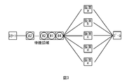
- FIG. 3 is a diagram illustrating a production line model.
- the product put into the production line model moves to the next cell after staying for a specified process time in the cell corresponding to each production apparatus.
- a predetermined number of cells are set. As a result, the predetermined number of products can stand by in the standby area.
- the line simulator performs a simulation from the start of loading of each product to the start cell at predetermined time intervals according to the loading order until all the products reach the goal.
- the line simulator By using the line simulator, it is possible to optimize the input order so that the objective function determined by the input order satisfies a predetermined condition with KPIs such as manufacturing lead time and manufacturing cost as objective functions.
- the objective function may be one or more. If there is one objective function, unidirectional optimization is performed. If there are two or more objective functions, multi-objective optimization is performed. From the obtained results, an input plan that meets the desired conditions will be adopted. However, if there is no result that meets the desired conditions of KPI, it is required to adjust the type and number of manufacturing equipment, for example. At this time, it is required to increase or decrease the number of manufacturing appliances.
- FIG. 4A is a functional block diagram showing the overall configuration of the information processing apparatus 100 according to the first embodiment.
- the information processing device 100 is a server or the like for optimization processing.
- the information processing apparatus 100 includes a manufacturing line model storage unit 10, a manufacturing master storage unit 20, an input order storage unit 30, a calculation result storage unit 40, an acquisition unit 50, and an optimization execution unit. It includes 60, a counting unit 70, a specific unit 80, a result output unit 90, and the like.
- FIG. 4B is a block diagram illustrating a hardware configuration of each part of the information processing apparatus 100.
- the information processing device 100 includes a CPU 101, a RAM 102, a storage device 103, an input device 104, a display device 105, and the like.
- the CPU (Central Processing Unit) 101 is a central processing unit.
- the CPU 101 includes one or more cores.
- the RAM (Random Access Memory) 102 is a volatile memory that temporarily stores a program executed by the CPU 101, data processed by the CPU 101, and the like.
- the storage device 103 is a non-volatile storage device. As the storage device 103, for example, a ROM (Read Only Memory), a solid state drive (SSD) such as a flash memory, a hard disk driven by a hard disk drive, or the like can be used.
- the storage device 103 stores the specific program according to this embodiment.
- the input device 104 is an input device such as a mouse and a keyboard.
- the display device 105 is a display device such as a liquid crystal display. The display device 105 displays the result output by the result output unit 90.
- each part of FIG. 4A is realized.
- hardware such as a dedicated circuit may be used as each part of FIG. 4A.
- the production line model storage unit 10 stores the production line model as illustrated in FIG.
- the manufacturing master storage unit 20 stores a manufacturing master in which each product type and a manufacturing apparatus capable of carrying out a manufacturing process for each product type are associated with each other.
- FIG. 5 is a diagram illustrating a manufacturing master.
- the manufacturing apparatus a can carry out the necessary manufacturing process for the product # 1, the product # 3, and the product # 4, but is necessary for the product # 2 and the product # 5. The manufacturing process cannot be carried out.
- the input order storage unit 30 stores the initial input order as illustrated in FIG. 2 (a).
- the initial input order is, for example, an order in which the order is arranged as ordered from the customer, and the user may input in advance using the input device 104.
- the initial input order may be generated by a random number. Since the initial input order is generated without considering the objective function, it is often not a good value for any objective function.
- the acquisition unit 50 acquires information necessary for the optimization calculation (step S1).
- the information required for the optimization calculation includes the production line model stored in the production line model storage unit 10. Further, the information required for the optimization calculation includes the manufacturing master illustrated in FIG. Further, the information required for the optimization calculation includes the initial input order stored in the input order storage unit 30.
- the optimization execution unit 60 performs an optimization calculation using the information acquired by the acquisition unit 50 in step S1 (step S2).
- a line simulation is performed according to the input order, and the manufacturing lead time and the manufacturing cost are acquired as objective functions for the simulation results from the start of product introduction to the start until all the products reach the goal.
- An evolutionary algorithm for example, Genetic Algorithm (GA) optimizes the input order so that the specified objective function becomes good.
- the counting unit 70 is not in the process of performing the manufacturing process, but is capable of performing the manufacturing process on the product.
- the number of products N1 transferred to the manufacturing apparatus is counted.
- the counting unit 70 carries out a manufacturing process for another product even though the manufacturing process can be carried out for the product.
- the number of products N2 that have been put on standby because they are inside are counted (step S3).
- the standby here means to stop at the beginning of the standby area for a specified time (0 ⁇ 0) or more.
- FIG. 7A it is assumed that product # 3, product # 2, and product # 1 are waiting in this order from the beginning to the end in the standby area.
- FIG. 7B it is assumed that the manufacturing apparatus b is in the process of manufacturing the product # 5, and the manufacturing apparatus c is in the process of manufacturing the product # 4. ..
- the product # 3 can be distributed to the manufacturing apparatus a or the manufacturing apparatus d.
- the process time in the manufacturing apparatus d is longer than the process time in the manufacturing apparatus a, it is assumed that the product # 3 has been moved to the manufacturing apparatus a as illustrated in FIG. 7B.
- the manufacturing apparatus d when the product arrives at the head of the standby area, the manufacturing apparatus d is not in the process of performing the manufacturing process, and the manufacturing process can be performed on the product, but the product is manufactured in another manner. It will be in the state of being moved to the device. Therefore, as illustrated in FIG. 7 (c), the number of products N1 of the manufacturing apparatus d is accumulated by one.
- the product # 2 moves to the top of the standby area as illustrated in FIG. 7 (a). In this state, since the manufacturing apparatus b and the manufacturing apparatus c are carrying out the manufacturing process for other products, the product # 2 stands by in the standby area from the manufacturing master of FIG.
- the manufacturing devices b and c are carrying out the manufacturing process for the other product even though the manufacturing process can be carried out for the product. That's why I made it stand by. Therefore, as illustrated in FIG. 7D, the number of products N2 of the manufacturing devices b and c is accumulated by one.
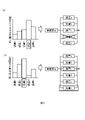
- FIG. 8 (a) and 8 (b) are diagrams illustrating the results of step S3.
- the number of products N1 is counted for each manufacturing apparatus.
- the number of products N2 is counted for each manufacturing apparatus.
- the number of products N1 and the number of products N2 are cumulative values for all the input orders simulated in the process of optimization in step S2. For example, when the charging order is changed 99 times from the initial loading order, the count values of the number of products N1 and the number of products N2 are the cumulative values of the number of products N1 and the number of products N2 for the simulation result for 100 times.
- the count values of the number of products N1 and the number of products N2 are stored in the calculation result storage unit 40.
- step S4 determines whether or not the KPI satisfies a predetermined condition with respect to the result of the line simulation in the optimum input order obtained by the execution of step S2 (step S4). If it is determined as "Yes” in step S4, it is not necessary to add or delete the manufacturing apparatus because the desired KPI is obtained. Therefore, when it is determined as "Yes” in step S4, the result output unit 90 causes the display device 105 to display the result of step S2, the result of step S3, and the like (step S5). After that, the execution of the flowchart ends.
- step S4 When it is determined as "No” in step S4, the specific unit 80 sets a threshold value for each of the number of products N1 and the number of products N2 (step S6). Next, the specifying unit 80 determines whether or not the number of products N1 is equal to or greater than the threshold value set in step S6 for each manufacturing apparatus (step S7). If there is a manufacturing apparatus determined to be "Yes” in step S7, the specific unit 80 deletes the manufacturing apparatus from the production line model as illustrated in FIG. 8A (step S8). The production line model storage unit 10 stores the updated production line model. In step S8, the result output unit 90 may display the manufacturing device to be deleted on the display device 105 so that the user can delete the manufacturing device from the manufacturing line model.
- the specifying unit 80 determines whether or not the number of products N2 is equal to or greater than the threshold value set in step S6 for each manufacturing apparatus (step S9). If there is a manufacturing apparatus determined to be "Yes” in step S9, the specific unit 80 adds another manufacturing apparatus to the production line model as illustrated in FIG. 8B (b). Step S10).
- the production line model storage unit 10 stores the updated production line model. After that, it is executed again from step S1.
- the result output unit 90 may display the manufacturing device to be added on the display device 105 so that the user can add the manufacturing device to the manufacturing line model.
- step S9 is executed without executing step S8. If “No” is determined in step S9, step S10 is not executed and is executed again from step S1.
- the manufacturing equipment by counting the number of products N1 and the number of products N2, it is possible to specify the manufacturing equipment to be increased or decreased. For example, by counting the number of products N1, the number of times the products are not distributed can be counted, so that the number of products N1 can be used as an index for the necessity of each manufacturing apparatus. Further, by counting the number of products N2, the number of times the product is kept on standby can be counted, so that the number of products N2 can be used as an index for the necessity of each manufacturing apparatus. By comparing the number of products N1 with the threshold value, it is possible to specify the manufacturing equipment to be deleted. Further, by comparing the number of products N2 with the threshold value, it is possible to specify the manufacturing equipment to be added.
- step S9 in FIG. 6 will be described with reference to FIGS. 9 (a) to 9 (e).
- the manufacturing master storage unit 20 stores the manufacturing master as illustrated in FIG. 9A.
- the manufacturing apparatus a is a dedicated apparatus capable of performing a manufacturing process necessary only for the product # 4.
- the manufacturing apparatus b is a dedicated apparatus capable of carrying out a manufacturing process necessary only for the product # 3.
- the manufacturing apparatus c is a general-purpose apparatus capable of carrying out a manufacturing process necessary for the product # 2, the product # 4, and the product # 5.
- the manufacturing devices d and e are also general-purpose devices like the manufacturing device c.
- step S3 it is assumed that the number of products N2 is obtained as shown in FIG. 9B. Further, as a result of step S3, it is assumed that the number of free waiting times waited at the beginning of the waiting area is obtained for each product type as shown in FIG. 9 (c).
- the results of FIGS. 9 (b) and 9 (c) are cumulative values for all input sequences simulated in the process of optimization in step S2.
- a manufacturing equipment having a product number N2 larger than a threshold value is a candidate.
- a threshold value for example, an average value
- the manufacturing devices b, c, and e are candidates. From these, a manufacturing apparatus capable of carrying out the manufacturing process for all the products in which the number of waiting times in FIG. 9 (c) is larger than the threshold value (for example, the average value) is selected. The selected manufacturing apparatus is deleted in step S8.
- FIG. 9D is a diagram illustrating the fixed cost required when adding a manufacturing apparatus. It is preferable to determine the number of manufacturing equipment to be added within the range that satisfies the desired cost. In order to keep the allowable cost (for example, 5000) as illustrated in FIG. 9 (e), the manufacturing process is performed for all the products (# 3, # 4, # 5) having a higher than average number of waiting times. If it is not possible to select a feasible manufacturing device, a manufacturing device capable of performing a manufacturing process is preferentially selected for a product having a large number of waiting times (# 4, # 3, # 5 in descending order).
- the type and number of manufacturing equipment for which the formula (n1 x x1 + n2 x x2 + n3 x x3 + n4 x x4 + n5 x x5) with the number of waiting times for each product as a coefficient is the largest is added to the additional manufacturing to shorten the manufacturing lead time. Select as a device. In this way, by multiplying the number of waiting times for each product as a coefficient, it becomes possible to add a manufacturing apparatus that can be preferentially manufactured to a product having a large number of waiting times.
- products # 1 to product # 5 are examples of a plurality of objects including a plurality of types.
- the order in which products are put into a production line is an example of a processing order in which a plurality of objects including a plurality of types are processed.
- a manufacturing device is an example of a working device.
- the acquisition unit 50 acquires first information indicating a processing order for processing a plurality of objects including a plurality of types, and among the plurality of types, a second indicating a type that can be processed by each of the plurality of working devices.
- This is an example of an acquisition unit that acquires information. Simulation of processing of the plurality of working devices based on the result of the counting unit 70 distributing each of the plurality of objects to any of the plurality of working devices based on the first information and the second information. The result of the simulation is obtained on the condition that each of the plurality of objects waits if the working device capable of processing the object is performing the processing on the other object.
- processing can be performed on the object to be sorted next, but the number N1 of the objects moved to the other working device is counted, and the object to be sorted next is counted.
- This is an example of a counting unit that counts the number of objects N2 that have been made to stand by because the processing can be performed but the processing is being performed for another object.
- the specific unit 80 is an example of a specific unit that specifies a work device to be increased / decreased with respect to the plurality of work devices according to at least one of the number of objects N1 and the number of objects N2.
Abstract
Description
20 製造マスタ格納部
30 投入順序格納部
40 演算結果格納部
50 取得部
60 最適化実行部
70 カウント部
80 特定部
90 結果出力部
100 情報処理装置
101 CPU
102 RAM
103 記憶装置
104 入力装置
105 表示装置
Claims (24)
- コンピュータに、
複数の種類を含む複数の対象物を処理する処理順序を示す第1情報を得る処理と、
前記複数の種類のうち、複数の作業装置の各々が処理可能な種類を示す第2情報を得る処理と、
前記第1情報及び前記第2情報に基づいて、前記複数の対象物のそれぞれを複数の作業装置のいずれかに振り分ける処理と、
前記複数の対象物のそれぞれを振り分けた結果に基づいて、前記複数の作業装置の処理に関するシミュレーションの結果を得る処理と、
前記複数の対象物の各々は、該対象物の処理を実施可能な前記作業装置が他の対象物に対する処理を実施中であれば待機する、という条件で、前記シミュレーションの結果から、前記複数の作業装置のそれぞれについて、次に振り分けられる対象物に対して処理を実施可能であるが他の作業装置に移動した対象物数N1をカウントし、次に振り分けられる対象物に対して処理を実施可能であるが他の対象物に対して処理中であるあるために待機させた対象物数N2をカウントする処理と、
前記対象物数N1および前記対象物数N2の少なくともいずれかに応じて、前記複数の作業装置に対して増減させる作業装置を特定する処理とを実行させることを特徴とする特定プログラム。 - 前記コンピュータに、
前記対象物数N1に応じて、前記複数の作業装置から削除される作業装置を特定する処理を実行させることを特徴とする請求項1に記載の特定プログラム。 - 前記コンピュータに、
前記対象物数N2に応じて、前記複数の作業装置に追加する作業装置を特定する処理を実行させることを特徴とする請求項1または請求項2に記載の特定プログラム。 - 前記複数の作業装置に追加する作業装置を特定する場合に、前記対象物数N2に加えて、前記複数の種類の各々の待機した回数を考慮することを特徴とする請求項3に記載の特定プログラム。
- 前記複数の作業装置に追加する作業装置を特定する場合に、前記対象物数N2に加えて、追加対象の作業装置の追加コストを考慮することを特徴とする請求項3または請求項4に記載の特定プログラム。
- 前記複数種類の処理順序は、処理順序に応じて定まる目的関数が良好となるように順次探索された順序であることを特徴とする請求項1から請求項5のいずれか一項に記載の特定プログラム。
- 前記複数種類の処理順序を探索する際に、前記目的関数を最適化する進化的アルゴリズムを用いることを特徴とする請求項1から請求項6のいずれか一項に記載の特定プログラム。
- 次に振り分けられる対象物について処理を実施可能な作業装置が複数あり、当該複数の作業装置が他の対象物に対して作業を行なっていない場合には、所定のルールに従って振分先が選択されることを特徴とする請求項1~請求項7のいずれか一項に記載の特定プログラム。
- 複数の種類を含む複数の対象物を処理する処理順序を示す第1情報を得る処理と、
前記複数の種類のうち、複数の作業装置の各々が処理可能な種類を示す第2情報を得る処理と、
前記第1情報及び前記第2情報に基づいて、前記複数の対象物のそれぞれを複数の作業装置のいずれかに振り分ける処理と、
前記複数の対象物のそれぞれを振り分けた結果に基づいて、前記複数の作業装置の処理に関するシミュレーションの結果を得る処理と、
前記複数の対象物の各々は、該対象物の処理を実施可能な前記作業装置が他の対象物に対する処理を実施中であれば待機する、という条件で、前記シミュレーションの結果から、前記複数の作業装置のそれぞれについて、次に振り分けられる対象物に対して処理を実施可能であるが他の作業装置に移動した対象物数N1をカウントし、次に振り分けられる対象物に対して処理を実施可能であるが他の対象物に対して処理中であるあるために待機させた対象物数N2をカウントする処理と、
前記対象物数N1および前記対象物数N2の少なくともいずれかに応じて、前記複数の作業装置に対して増減させる作業装置を特定する処理とをコンピュータが実行することを特徴とする特定方法。 - 前記対象物数N1に応じて、前記複数の作業装置から削除される作業装置を特定する処理を前記コンピュータが実行することを特徴とする請求項9に記載の特定方法。
- 前記対象物数N2に応じて、前記複数の作業装置に追加する作業装置を特定する処理を前記コンピュータが実行することを特徴とする請求項9または請求項10に記載の特定方法。
- 前記複数の作業装置に追加する作業装置を特定する場合に、前記対象物数N2に加えて、前記複数の種類の各々の待機した回数を考慮することを特徴とする請求項11に記載の特定方法。
- 前記複数の作業装置に追加する作業装置を特定する場合に、前記対象物数N2に加えて、追加対象の作業装置の追加コストを考慮することを特徴とする請求項11または請求項12に記載の特定方法。
- 前記複数種類の処理順序は、処理順序に応じて定まる目的関数が良好となるように順次探索された順序であることを特徴とする請求項9から請求項13のいずれか一項に記載の特定方法。
- 前記複数種類の処理順序を探索する際に、前記目的関数を最適化する進化的アルゴリズムを用いることを特徴とする請求項9から請求項14のいずれか一項に記載の特定方法。
- 次に振り分けられる対象物について処理を実施可能な作業装置が複数あり、当該複数の作業装置が他の対象物に対して作業を行なっていない場合には、所定のルールに従って振分先が選択されることを特徴とする請求項9~請求項15のいずれか一項に記載の特定方法。
- 複数の種類を含む複数の対象物を処理する処理順序を示す第1情報を取得し、前記複数の種類のうち、複数の作業装置の各々が処理可能な種類を示す第2情報を取得する取得部と、
前記第1情報及び前記第2情報に基づいて、前記複数の対象物のそれぞれを複数の作業装置のいずれかに振り分けた結果に基づいて、前記複数の作業装置の処理に関するシミュレーションの結果を得て、前記複数の対象物の各々は該対象物の処理を実施可能な前記作業装置が他の対象物に対する処理を実施中であれば待機する、という条件で、前記シミュレーションの結果から、前記複数の作業装置のそれぞれについて、次に振り分けられる対象物に対して処理を実施可能であるが他の作業装置に移動した対象物数N1をカウントし、次に振り分けられる対象物に対して処理を実施可能であるが他の対象物に対して処理中であるあるために待機させた対象物数N2をカウントするカウント部と、
前記対象物数N1および前記対象物数N2の少なくともいずれかに応じて、前記複数の作業装置に対して増減させる作業装置を特定する特定部と、を備えることを特徴とする情報処理装置。 - 前記特定部は、前記対象物数N1に応じて、前記複数の作業装置から削除される作業装置を特定することを特徴とする請求項17に記載の情報処理装置。
- 前記特定部は、前記対象物数N2に応じて、前記複数の作業装置に追加する作業装置を特定することを特徴とする請求項17または請求項18に記載の情報処理装置。
- 前記特定部は、前記複数の作業装置に追加する作業装置を特定する場合に、前記対象物数N2に加えて、前記複数の種類の各々の待機した回数を考慮することを特徴とする請求項19に記載の情報処理装置。
- 前記特定部は、前記複数の作業装置に追加する作業装置を特定する場合に、前記対象物数N2に加えて、追加対象の作業装置の追加コストを考慮することを特徴とする請求項19または請求項20に記載の情報処理装置。
- 前記複数種類の処理順序は、処理順序に応じて定まる目的関数が良好となるように順次探索された順序であることを特徴とする請求項17から請求項21のいずれか一項に記載の情報処理装置。
- 前記特定部は、前記複数種類の処理順序を探索する際に、前記目的関数を最適化する進化的アルゴリズムを用いることを特徴とする請求項17から請求項22のいずれか一項に記載の情報処理装置。
- 次に振り分けられる対象物について処理を実施可能な作業装置が複数あり、当該複数の作業装置が他の対象物に対して作業を行なっていない場合には、所定のルールに従って振分先が選択されることを特徴とする請求項17~請求項23のいずれか一項に記載の情報処理装置。
Priority Applications (5)
| Application Number | Priority Date | Filing Date | Title |
|---|---|---|---|
| CN202080107188.3A CN116490831A (zh) | 2020-12-25 | 2020-12-25 | 信息处理装置、确定方法、以及确定程序 |
| JP2022570955A JP7368785B2 (ja) | 2020-12-25 | 2020-12-25 | 情報処理装置、特定方法、および特定プログラム |
| EP20966999.3A EP4270125A4 (en) | 2020-12-25 | 2020-12-25 | INFORMATION PROCESSING DEVICE, DESIGNATION METHOD AND DESIGNATION PROGRAM |
| PCT/JP2020/048768 WO2022137513A1 (ja) | 2020-12-25 | 2020-12-25 | 情報処理装置、特定方法、および特定プログラム |
| US18/307,844 US20240095428A1 (en) | 2020-12-25 | 2023-04-27 | Information processing device, specifying method, and non-transitory computer-readable recording medium storing specifying program |
Applications Claiming Priority (1)
| Application Number | Priority Date | Filing Date | Title |
|---|---|---|---|
| PCT/JP2020/048768 WO2022137513A1 (ja) | 2020-12-25 | 2020-12-25 | 情報処理装置、特定方法、および特定プログラム |
Related Child Applications (1)
| Application Number | Title | Priority Date | Filing Date |
|---|---|---|---|
| US18/307,844 Continuation US20240095428A1 (en) | 2020-12-25 | 2023-04-27 | Information processing device, specifying method, and non-transitory computer-readable recording medium storing specifying program |
Publications (1)
| Publication Number | Publication Date |
|---|---|
| WO2022137513A1 true WO2022137513A1 (ja) | 2022-06-30 |
Family
ID=82157440
Family Applications (1)
| Application Number | Title | Priority Date | Filing Date |
|---|---|---|---|
| PCT/JP2020/048768 WO2022137513A1 (ja) | 2020-12-25 | 2020-12-25 | 情報処理装置、特定方法、および特定プログラム |
Country Status (5)
| Country | Link |
|---|---|
| US (1) | US20240095428A1 (ja) |
| EP (1) | EP4270125A4 (ja) |
| JP (1) | JP7368785B2 (ja) |
| CN (1) | CN116490831A (ja) |
| WO (1) | WO2022137513A1 (ja) |
Citations (8)
| Publication number | Priority date | Publication date | Assignee | Title |
|---|---|---|---|---|
| JPH11282923A (ja) * | 1998-03-31 | 1999-10-15 | Mitsubishi Electric Corp | 循環型製造プロセス日程計画方法 |
| JP2002182732A (ja) * | 2000-12-19 | 2002-06-26 | Toyota Motor Corp | 製造原価見積りシステム |
| JP2005055956A (ja) * | 2003-08-05 | 2005-03-03 | Toyota Central Res & Dev Lab Inc | 原因・経路推定方法 |
| JP2005301653A (ja) | 2004-04-12 | 2005-10-27 | Oki Electric Ind Co Ltd | 製造工程管理方法 |
| JP2006512628A (ja) * | 2002-06-07 | 2006-04-13 | 日本電産サンキョー株式会社 | 自動誘導式パレットを用いた生産ラインおよび生産ライン設計支援システム本出願は米国特許法(35U.S.C.)第119条に基づく2002年6月7日出願の米国仮出願No.60/387,347の優先権を主張するものであり、当該仮出願の全開示もまた参照により本出願に包含される。 |
| JP2015087803A (ja) | 2013-10-28 | 2015-05-07 | 株式会社日立製作所 | 部品設備割付装置、部品設備割付方法、及びプログラム |
| JP2016024799A (ja) * | 2014-07-25 | 2016-02-08 | Jfeスチール株式会社 | 鉄鋼製品の生産計画方法およびプログラム |
| JP2020047301A (ja) | 2016-11-30 | 2020-03-26 | パナソニックIpマネジメント株式会社 | 設備構成作成支援システムおよび設備構成作成支援方法 |
Family Cites Families (2)
| Publication number | Priority date | Publication date | Assignee | Title |
|---|---|---|---|---|
| WO2017187517A1 (ja) * | 2016-04-26 | 2017-11-02 | 富士通株式会社 | 製品投入計画策定装置、製品投入計画策定方法及び製品投入計画策定プログラム |
| CN108460463B (zh) * | 2018-03-20 | 2020-09-01 | 合肥工业大学 | 基于改进遗传算法的高端装备流水线生产调度方法 |
-
2020
- 2020-12-25 JP JP2022570955A patent/JP7368785B2/ja active Active
- 2020-12-25 CN CN202080107188.3A patent/CN116490831A/zh active Pending
- 2020-12-25 EP EP20966999.3A patent/EP4270125A4/en active Pending
- 2020-12-25 WO PCT/JP2020/048768 patent/WO2022137513A1/ja active Application Filing
-
2023
- 2023-04-27 US US18/307,844 patent/US20240095428A1/en active Pending
Patent Citations (8)
| Publication number | Priority date | Publication date | Assignee | Title |
|---|---|---|---|---|
| JPH11282923A (ja) * | 1998-03-31 | 1999-10-15 | Mitsubishi Electric Corp | 循環型製造プロセス日程計画方法 |
| JP2002182732A (ja) * | 2000-12-19 | 2002-06-26 | Toyota Motor Corp | 製造原価見積りシステム |
| JP2006512628A (ja) * | 2002-06-07 | 2006-04-13 | 日本電産サンキョー株式会社 | 自動誘導式パレットを用いた生産ラインおよび生産ライン設計支援システム本出願は米国特許法(35U.S.C.)第119条に基づく2002年6月7日出願の米国仮出願No.60/387,347の優先権を主張するものであり、当該仮出願の全開示もまた参照により本出願に包含される。 |
| JP2005055956A (ja) * | 2003-08-05 | 2005-03-03 | Toyota Central Res & Dev Lab Inc | 原因・経路推定方法 |
| JP2005301653A (ja) | 2004-04-12 | 2005-10-27 | Oki Electric Ind Co Ltd | 製造工程管理方法 |
| JP2015087803A (ja) | 2013-10-28 | 2015-05-07 | 株式会社日立製作所 | 部品設備割付装置、部品設備割付方法、及びプログラム |
| JP2016024799A (ja) * | 2014-07-25 | 2016-02-08 | Jfeスチール株式会社 | 鉄鋼製品の生産計画方法およびプログラム |
| JP2020047301A (ja) | 2016-11-30 | 2020-03-26 | パナソニックIpマネジメント株式会社 | 設備構成作成支援システムおよび設備構成作成支援方法 |
Non-Patent Citations (1)
| Title |
|---|
| See also references of EP4270125A4 |
Also Published As
| Publication number | Publication date |
|---|---|
| JP7368785B2 (ja) | 2023-10-25 |
| CN116490831A (zh) | 2023-07-25 |
| JPWO2022137513A1 (ja) | 2022-06-30 |
| EP4270125A1 (en) | 2023-11-01 |
| EP4270125A4 (en) | 2024-02-21 |
| US20240095428A1 (en) | 2024-03-21 |
Similar Documents
| Publication | Publication Date | Title |
|---|---|---|
| Kulak et al. | Joint order batching and picker routing in single and multiple-cross-aisle warehouses using cluster-based tabu search algorithms | |
| JP6460095B2 (ja) | 学習モデル選択システム、学習モデル選択方法及びプログラム | |
| JP6962539B2 (ja) | 業務計画最適化方法 | |
| US10642257B2 (en) | Tree search-based scheduling method and electronic apparatus using the same | |
| US8983881B2 (en) | Benchmarking progressive systems for solving combinatorial problems | |
| Li et al. | A heuristic-search genetic algorithm for multi-stage hybrid flow shop scheduling with single processing machines and batch processing machines | |
| US11321722B2 (en) | Assortment optimization using incremental swapping with demand transference | |
| JP5134601B2 (ja) | 生産スケジュール作成装置 | |
| JP2018026070A (ja) | 作業編成装置、作業編成方法および作業編成プログラム | |
| CN110147596B (zh) | 一种航空产品生产能力评估方法 | |
| JPWO2018185899A1 (ja) | ライブラリ検索装置、ライブラリ検索システム、及びライブラリ検索方法 | |
| WO2022137513A1 (ja) | 情報処理装置、特定方法、および特定プログラム | |
| Ebrahim et al. | Understanding responsiveness in manufacturing operations | |
| JP6214835B2 (ja) | 作業指導割当システム及び作業指導割当方法 | |
| Venkatadri et al. | A multi-commodity network flow-based formulation for the multi-period cell formation problem | |
| JP6995694B2 (ja) | 加工設備特定支援装置、加工設備特定支援方法、および、加工設備特定支援システム | |
| Xie et al. | Efficient order picking methods in robotic mobile fulfillment systems | |
| van der Gaast et al. | Dynamic batching for order picking in warehouses | |
| JP2003280714A (ja) | 生産スケジューリング方法及び生産スケジューリング装置 | |
| JP6688616B2 (ja) | シミュレーション装置 | |
| WO2021234903A1 (ja) | 情報処理装置、作業計画特定方法、および作業計画特定プログラム | |
| WO2022013921A1 (ja) | 作業計画特定プログラム、作業計画特定方法、および情報処理装置 | |
| WO2023276108A1 (ja) | シミュレーションプログラム、シミュレーション方法、および情報処理装置 | |
| CN116663827A (zh) | 一种柔性作业车间机器选择方法、系统、终端及介质 | |
| JP4930152B2 (ja) | 条鋼製品の生産計画方法、その製造方法及びプログラム |
Legal Events
| Date | Code | Title | Description |
|---|---|---|---|
| 121 | Ep: the epo has been informed by wipo that ep was designated in this application |
Ref document number: 20966999 Country of ref document: EP Kind code of ref document: A1 |
|
| ENP | Entry into the national phase |
Ref document number: 2022570955 Country of ref document: JP Kind code of ref document: A |
|
| WWE | Wipo information: entry into national phase |
Ref document number: 202080107188.3 Country of ref document: CN |
|
| NENP | Non-entry into the national phase |
Ref country code: DE |
|
| ENP | Entry into the national phase |
Ref document number: 2020966999 Country of ref document: EP Effective date: 20230725 |