WO2022130632A1 - ガイドワイヤの製造方法およびガイドワイヤ - Google Patents
ガイドワイヤの製造方法およびガイドワイヤ Download PDFInfo
- Publication number
- WO2022130632A1 WO2022130632A1 PCT/JP2020/047510 JP2020047510W WO2022130632A1 WO 2022130632 A1 WO2022130632 A1 WO 2022130632A1 JP 2020047510 W JP2020047510 W JP 2020047510W WO 2022130632 A1 WO2022130632 A1 WO 2022130632A1
- Authority
- WO
- WIPO (PCT)
- Prior art keywords
- guide wire
- layer
- functional group
- fluororesin
- resin
- Prior art date
- Legal status (The legal status is an assumption and is not a legal conclusion. Google has not performed a legal analysis and makes no representation as to the accuracy of the status listed.)
- Ceased
Links
Images


Classifications
-
- A—HUMAN NECESSITIES
- A61—MEDICAL OR VETERINARY SCIENCE; HYGIENE
- A61M—DEVICES FOR INTRODUCING MEDIA INTO, OR ONTO, THE BODY; DEVICES FOR TRANSDUCING BODY MEDIA OR FOR TAKING MEDIA FROM THE BODY; DEVICES FOR PRODUCING OR ENDING SLEEP OR STUPOR
- A61M25/00—Catheters; Hollow probes
- A61M25/01—Introducing, guiding, advancing, emplacing or holding catheters
- A61M25/09—Guide wires
Definitions
- the present invention relates to a method for manufacturing a guide wire and a guide wire.
- a guide wire is used to guide the medical device to the treatment site.
- a fluororesin such as PTFE or PFA is applied to the outermost surface of the metal core wire so that the guide wire can smoothly proceed in a branched or curved blood vessel and reach the treatment site smoothly.
- a coating technique has been proposed (see, for example, Patent Document 1).
- an adhesive layer for adhering the core wire and the fluororesin is provided.
- the frictional force can be reduced by suppressing the chemical bonding force between the outermost surface of the guide wire and the inner peripheral surface of the blood vessel, and the improvement of the slidability makes it possible to reduce the frictional force in the body cavity. Smooth operation is expected.
- the present invention is to provide a method for manufacturing a guide wire and a guide wire capable of further improving the slidability in a body cavity.
- One aspect of the present disclosure is (1) [A] Using particles formed of a fluororesin having an adhesive functional group and having an average particle size of 1 ⁇ m or less specified in JIS Z 8825, the particles are coated on a metal core wire. And the process to do [B] After the step [A], a step of forming the first layer by firing the core wire coated with the particles, and a step of forming the first layer. [C] A guide comprising, after the step [B], a step of forming a second layer on the outer peripheral surface of the first layer using a resin different from the fluororesin having the adhesive functional group.
- the method for producing the wire, and (2) the resin different from the fluororesin having the adhesive functional group is polytetrafluoroethylene (PTFE), tetrafluoroethylene / perfluoroalkoxyethylene copolymer (PFA), and four.
- PTFE polytetrafluoroethylene
- PFA perfluoroalkoxyethylene copolymer
- a metal core wire, a first resin layer formed on the outer periphery of the core wire, and a second resin layer formed on the outer periphery of the first resin layer are provided.
- the first resin layer has a fluororesin having an adhesive functional group and has.
- the fluororesin having an adhesive functional group is a guide wire composed of particles having an average particle size of 1 ⁇ m or less specified in JIS Z 8825.
- a metal core wire, a first resin layer formed on the outer periphery of the core wire, and a second resin layer formed on the outer periphery of the first resin layer are provided.
- the first resin layer has a fluororesin having an adhesive functional group and has.
- the "fluororesin having an adhesive functional group” refers to a functional group that may be involved in adhesion to a material such as an adjacent resin or metal (hereinafter, also referred to as "adhesive functional group”). It means a fluororesin having. Further, the "resin different from the fluororesin having an adhesive functional group” means a resin containing no fluororesin having an adhesive functional group.
- the present invention can provide a method for manufacturing a guide wire and a guide wire capable of improving slidability in a body cavity.
- a fluororesin having an adhesive functional group having adhesiveness to both a metal and a fluororesin as a material constituting an adhesive layer for adhering the core wire and the outer layer resin is used.
- the particle size of the fluororesin particles having the adhesive functional group is relatively coarse, an uneven shape is likely to occur on the surface of the adhesive layer, and as a result, an uneven shape appears on the outermost surface, depending on the size of the uneven shape. May not provide sufficient slidability.
- a melting process at a high temperature can be considered.
- the method of performing the above-mentioned melting treatment causes a long manufacturing time.
- the fluororesin having an adhesive functional group is melted at a high temperature, the melted resin may be washed away or the melted resin may be attracted by gravity to cause a difference in thickness between the upper and lower sides.
- An object of the present disclosure is to provide a method for manufacturing a guide wire and a guide wire that can further improve the slidability in a body cavity by suppressing the unevenness appearing on the outermost surface of the guide wire.
- a resin different from the fluororesin having the adhesive functional group (hereinafter, also referred to as “coating resin”) is used, and the second layer is formed on the outer peripheral surface of the first layer. It has a forming process.
- coating resin a resin different from the fluororesin having the adhesive functional group
- Step A particles (adhesive resin particles) having an average particle size of 1 ⁇ m or less specified in JIS Z 8825, which are particles formed of a fluororesin (adhesive resin) having an adhesive functional group, are used. This is the process of applying particles onto a metal core wire.
- the core wire is a metal wire that serves as the core material of the guide wire.
- the material constituting the core wire for example, stainless steel such as SUS304, superelastic alloy such as Ni—Ti alloy, etc. are used from the viewpoint of improving the flexibility of the guide wire and imparting antithrombotic property and biocompatibility. Can be adopted.
- the dimensions of the core wire are, for example, a total length of 1,800 to 3,000 mm and an outer diameter of 0.03 mm to 0.46 mm.
- the adhesive resin is a fluororesin having an adhesive functional group.
- the adhesive resin can be composed of, for example, a polymer having a fluorine-containing ethylenic monomer unit.
- the core wire and the second layer described later can be strongly adhered by interposing the first layer formed of the adhesive resin particles between the core wire and the second layer. ..
- the polymer constituting the adhesive resin can be used alone or in combination of two or more.
- fluorine-containing ethylenic monomer examples include ethylene tetrafluoride, vinylidene fluoride, chlorotrifluoroethylene, vinyl fluoride, hexafluoropropylene, hexafluoroisobutene, and per.
- Fluorines (alkyl vinyl ethers), monomers represented by the following formula (1) and the like can be mentioned.
- CH 2 CX 1 (CF 2 ) n X 2 ... (1)
- X 1 represents a hydrogen atom or a fluorine atom
- X 2 represents a hydrogen atom, a fluorine atom or a chlorine atom
- n represents an integer of 1 to 10.
- the polymer constituting the adhesive resin may have, for example, a fluorine-free monomer unit such as a fluorine-free ethylenic monomer unit together with the fluorine-containing ethylenic monomer unit.
- a fluorine-free monomer unit such as a fluorine-free ethylenic monomer unit together with the fluorine-containing ethylenic monomer unit.
- fluorine-free ethylenic monomer giving the fluorine-free ethylenic monomer unit examples include ethylene, propylene, 1-butene, 2-butene, vinyl chloride, vinylidene chloride and the like.
- the polymer constituting the adhesive resin is preferably a tetrafluoroethylene / perfluoroalkoxyethylene copolymer (PFA).
- PFA tetrafluoroethylene / perfluoroalkoxyethylene copolymer
- the tetrafluoroethylene / perfluoroalkoxyethylene copolymer has a high melting point, good compatibility with polytetrafluoroethylene (PTFE), and high mechanical properties.
- the adhesive functional group in the adhesive resin is a functional group that can be involved in adhesion to an adjacent material such as a resin or metal.
- the adhesive functional group include a functional group capable of reacting with a polar functional group possessed by an adjacent material such as a resin or a metal, a functional group capable of intermolecular interaction such as a hydrogen bond, and the like.
- the adhesive functional group may be at least one of the main chain end and the side chain in the fluororesin.
- the adhesive functional group preferably has a carbonyl group.
- halogen atom constituting the halogenoformyl group examples include a fluorine atom and a chlorine atom.
- the carbonate group and the halogenoformyl group are preferable as the adhesive functional group from the viewpoint of improving the reactivity (adhesiveness) with the adjacent material.
- the adhesive resin particles used in this step are particles having an average particle size of 1 ⁇ m or less based on JIS Z 8825: 2013 (“particle size analysis-laser diffraction / scattering method”).
- the upper limit of the average particle size of the adhesive resin particles is preferably 0.8 ⁇ m. This makes it possible to further reduce the unevenness of the outermost surface of the guide wire.
- the lower limit of the average particle size of the adhesive resin particles is preferably 0.1 ⁇ m from the viewpoint of ease of production.
- the particle size distribution of the adhesive resin particles is preferably 0.2 to 1 ⁇ m from the viewpoint of dispersibility.
- Adhesive resin particles may be produced by mixing a polymerization initiator, a chain transfer agent, a solvent and the like in a desired ratio and polymerizing the above-mentioned monomers.
- Examples of the adhesive functional group-containing ethylenic monomer include fluorine such as perfluoroacrylic acid fluoride, 1-fluoroacrylic acid fluoride, acrylate fluoride, 1-trifluoromethacrylic acid fluoride, and perfluorobutenoic acid. Quantities: Acrylic acid, methacrylic acid, acrylic acid chloride, vinylene carbonate and the like.
- polymerization initiator examples include diisopropyl peroxydicarbonate, di-n-propylperoxydicarbonate, t-butylperoxyisopropylcarbonate, bis (4-t-butylcyclohexyl) peroxydicarbonate, and di-2-.
- peroxycarbonate such as ethylhexyl peroxydicarbonate.
- the chain transfer agent is added, for example, to adjust the molecular weight.
- examples of the chain transfer agent include hydrocarbons such as isopentane, n-pentane, n-hexane and cyclohexane; alcohols such as methanol and ethanol; halogenated hydrocarbons such as carbon tetrachloride, chloroform, methylene chloride and methyl chloride. Can be mentioned.
- Examples of the solvent include hydrochlorofluoroalkanes such as CH 3 CClF 2 , CH 3 CCl 2 F, CF 3 CF 2 CCl 2 H, CF 2 ClCF 2 CF HCl; CF 2 ClCFClCF 2 CF 3 , CF 3 CFClCFClCF 3 and the like. Chlorofluoroalkanes; CF 3 CF 2 CF 2 CF 3 , CF 3 CF 2 CF 2 CF 2 CF 3 , CF 3 CF 2 CF 2 CF 2 CF 3 and other perfluoroalkanes; Examples thereof include perfluorocycloalkanes.
- hydrochlorofluoroalkanes such as CH 3 CClF 2 , CH 3 CCl 2 F, CF 3 CF 2 CCl 2 H, CF 2 ClCF 2 CF HCl; CF 2 ClCFClCF 2 CF 3 , CF 3 CFClCFClCF 3 and the like
- polymerization method examples include solution polymerization, bulk polymerization, emulsion polymerization, suspension polymerization and the like.
- the adhesive resin particles used in [Step A] of the present disclosure may be produced, for example, by further pulverizing the particles obtained by the above polymerization method, if necessary.
- Examples of the crushing method include a method of crushing using a crushing device such as a high-pressure collision crushing device and a high-speed shear stirrer.
- the method of applying the adhesive resin particles onto the metal core wire is not particularly limited as long as the first layer having a predetermined thickness can be formed.
- a coating method for example, adhesive resin particles are dispersed in a dispersion medium to prepare a dispersion liquid, and the core wire is immersed in the dispersion liquid to coat the adhesive resin particles on the core wire (immersion method). ), A method of preparing a dispersion liquid in the same manner as described above, and spraying and applying the dispersion liquid onto the core wire (spray method) and the like.
- Step B This step is a step of forming the first layer by firing the core wire coated with the particles after the step [A].
- the strong adhesive force (adhesiveness) between the first layer and the core wire and the coating resin of the second layer has high reactivity (adhesiveness) between the adhesive functional group of the adhesive resin and the metal material constituting the core wire.
- reactivity with polar groups such as carboxy groups or hydroxyl groups present on the surface of metal core wires
- high reactivity with the coating resin constituting the second layer for example, carboxy groups or carboxy groups present on the surface of the coating resin. It is considered that this is due to the strong bonding force associated with (reactivity with polar groups such as hydroxyl groups).
- This step is a step of forming the second layer on the outer peripheral surface of the first layer by using a resin (coating resin) different from the fluororesin having the adhesive functional group after the step [B].
- resins other than the above fluororesin include nylon, urethane and the like.
- the method for forming the second layer is not particularly limited as long as a layer of a coating resin having a predetermined thickness can be formed.
- a method for forming the second layer for example, a granular coating resin is dispersed in a dispersion medium to prepare a dispersion liquid, and the core wire after forming the first layer obtained in [Step B] is placed in the dispersion liquid.
- a method of forming a second layer by immersing and drying, a dispersion liquid is prepared in the same manner as described above, sprayed onto the core wire after forming the first layer, applied, and then dried to form the second layer. How to do it, etc.
- the same firing as in the above-mentioned [Step B] may be performed.
- the firing conditions such as firing temperature, firing time, and atmosphere can be appropriately selected depending on the material constituting the second layer.
- FIGS. 1 and 2 are schematic cross-sectional views showing an embodiment of a guide wire.
- the guide wire 1 is roughly composed of a core wire 11, a first resin layer 21, and a second resin layer 31.
- the configurations of the core wire 11, the first resin layer 21, and the second resin layer 31 are the same as the configurations of the core wire, the first layer, and the second layer described in the section ⁇ Manufacturing method of guide wire>, respectively. Therefore, detailed description here will be omitted.
- the first resin layer 21 is a resin layer formed on the outer periphery of the core wire 11.
- the first resin layer 21 has a fluororesin having an adhesive functional group.
- the fluororesin having an adhesive functional group is composed of particles having an average particle size of 1 ⁇ m or less specified in JIS Z8825.
- the second resin layer 31 is a resin layer formed on the outer periphery of the first resin layer 21.
- the method for manufacturing the guide wire for example, the method described in the section ⁇ Manufacturing method for guide wire> can be adopted.
- the first resin layer has a fluororesin having an adhesive functional group, and the surface roughness on the outer surface of the second resin layer is 1 ⁇ m in the arithmetic average roughness (Ra) specified in JIS B 0601: 1994. Is less than.
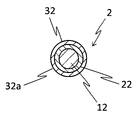
- the core wire 12 is a metal wire that serves as a core material for the guide wire 2.
- the second resin layer 32 is a resin layer formed on the outer periphery of the first resin layer 22.
- the surface roughness of the outer surface 32a of the second resin layer 32 is less than 1 ⁇ m in the arithmetic mean roughness (Ra) specified in JIS B 0601: 1994.
- the method for manufacturing the guide wire 2 for example, the method described in the section ⁇ Manufacturing method for guide wire> can be adopted.
- a method for manufacturing a guide wire has been described by exemplifying a compound such as a specific monomer.
- the method for producing the guide wire of the present disclosure is not limited to the above-exemplified compounds and the like.
Landscapes
- Health & Medical Sciences (AREA)
- Life Sciences & Earth Sciences (AREA)
- Biophysics (AREA)
- Pulmonology (AREA)
- Engineering & Computer Science (AREA)
- Anesthesiology (AREA)
- Biomedical Technology (AREA)
- Heart & Thoracic Surgery (AREA)
- Hematology (AREA)
- Animal Behavior & Ethology (AREA)
- General Health & Medical Sciences (AREA)
- Public Health (AREA)
- Veterinary Medicine (AREA)
- Media Introduction/Drainage Providing Device (AREA)
Abstract
体腔内での摺動性を向上することが可能なガイドワイヤの製造方法の提供を目的とする。 当該ガイドワイヤの製造方法は、[A]接着性官能基を有するフッ素樹脂で形成された粒子であってJIS Z 8825に規定の平均粒径が1μm以下である粒子を用い、前記粒子を金属製のコアワイヤ上に塗布する工程と、[B]前記[A]工程の後、前記粒子が塗布された前記コアワイヤの焼成により第1層を形成する工程と、[C]前記[B]工程の後、前記接着性官能基を有するフッ素樹脂とは異なる樹脂を用い、前記第1層の外周面上に第2層を形成する工程と、を備えている。
Description
本発明は、ガイドワイヤの製造方法およびガイドワイヤに関する。
例えば、血管内の処置部位にバルーンカテーテルなどの医療器具を挿入する際、上記医療器具を処置部位まで案内するためにガイドワイヤが用いられる。
このようなガイドワイヤにおいては、例えば、分岐や湾曲した血管内を円滑に進行し、処置部位まで円滑に到達することができるように、金属製コアワイヤの最表面にPTFE、PFAなどのフッ素樹脂をコートする技術が提案されている(例えば、特許文献1参照)。
上述の技術では、例えば、コアワイヤとフッ素樹脂との間に両者を接着するための接着層が設けられる。このようなガイドワイヤによれば、ガイドワイヤの最表面と血管内周面との間の化学的な結合力の抑制により摩擦力の低減することができ、摺動性の向上により体腔内での操作の円滑化が期待される。
本発明は、体腔内での摺動性をより向上することが可能なガイドワイヤの製造方法およびガイドワイヤを提供することにある。
本開示の一つの態様は、
(1)[A]接着性官能基を有するフッ素樹脂で形成された粒子であってJIS Z 8825に規定の平均粒径が1μm以下である粒子を用い、前記粒子を金属製のコアワイヤ上に塗布する工程と、
[B]前記[A]工程の後、前記粒子が塗布された前記コアワイヤの焼成により第1層を形成する工程と、
[C]前記[B]工程の後、前記接着性官能基を有するフッ素樹脂とは異なる樹脂を用い、前記第1層の外周面上に第2層を形成する工程と、を備えているガイドワイヤの製造方法、並びに
(2)前記接着性官能基を有するフッ素樹脂とは異なる樹脂が、ポリテトラフルオロエチレン(PTFE)、四フッ化エチレン・パーフルオロアルコキシエチレン共重合体(PFA)、および四フッ化エチレン・六フッ化プロピレン共重合体(FEP)からなる群より選ばれた少なくとも1種である前記(1)に記載のガイドワイヤの製造方法、である。
(1)[A]接着性官能基を有するフッ素樹脂で形成された粒子であってJIS Z 8825に規定の平均粒径が1μm以下である粒子を用い、前記粒子を金属製のコアワイヤ上に塗布する工程と、
[B]前記[A]工程の後、前記粒子が塗布された前記コアワイヤの焼成により第1層を形成する工程と、
[C]前記[B]工程の後、前記接着性官能基を有するフッ素樹脂とは異なる樹脂を用い、前記第1層の外周面上に第2層を形成する工程と、を備えているガイドワイヤの製造方法、並びに
(2)前記接着性官能基を有するフッ素樹脂とは異なる樹脂が、ポリテトラフルオロエチレン(PTFE)、四フッ化エチレン・パーフルオロアルコキシエチレン共重合体(PFA)、および四フッ化エチレン・六フッ化プロピレン共重合体(FEP)からなる群より選ばれた少なくとも1種である前記(1)に記載のガイドワイヤの製造方法、である。
本開示の別の態様は、
金属製のコアワイヤと、前記コアワイヤの外周に形成される第1樹脂層と、前記第1樹脂層の外周に形成される第2樹脂層とを備え、
前記第1樹脂層は、接着性官能基を有するフッ素樹脂を有し、
前記接着性官能基を有するフッ素樹脂は、JIS Z 8825に規定の平均粒径が1μm以下である粒子により構成されているガイドワイヤ、である。
金属製のコアワイヤと、前記コアワイヤの外周に形成される第1樹脂層と、前記第1樹脂層の外周に形成される第2樹脂層とを備え、
前記第1樹脂層は、接着性官能基を有するフッ素樹脂を有し、
前記接着性官能基を有するフッ素樹脂は、JIS Z 8825に規定の平均粒径が1μm以下である粒子により構成されているガイドワイヤ、である。
本開示の更に別の態様は、
金属製のコアワイヤと、前記コアワイヤの外周に形成される第1樹脂層と、前記第1樹脂層の外周に形成される第2樹脂層とを備え、
前記第1樹脂層は、接着性官能基を有するフッ素樹脂を有し、
前記第2樹脂層の外表面における表面粗さが、JIS B 0601:1994に規定の算術平均粗さ(Ra)で1μm未満であるガイドワイヤ、である。
金属製のコアワイヤと、前記コアワイヤの外周に形成される第1樹脂層と、前記第1樹脂層の外周に形成される第2樹脂層とを備え、
前記第1樹脂層は、接着性官能基を有するフッ素樹脂を有し、
前記第2樹脂層の外表面における表面粗さが、JIS B 0601:1994に規定の算術平均粗さ(Ra)で1μm未満であるガイドワイヤ、である。
なお、本明細書において、「接着性官能基を有するフッ素樹脂」とは、隣接する樹脂や金属などの材料との接着に関与し得る官能基(以下、「接着性官能基」ともいう)を有するフッ素樹脂を意味する。また、「接着性官能基を有するフッ素樹脂とは異なる樹脂」とは、上記接着性官能基を有するフッ素樹脂を含まない樹脂を意味する。
本発明は、体腔内での摺動性を向上することが可能なガイドワイヤの製造方法およびガイドワイヤを提供することができる。
本開示のガイドワイヤの製造方法およびガイドワイヤにおいては、コアワイヤと外層樹脂とを接着する接着層を構成する材料として、金属およびフッ素樹脂のいずれにも接着性を有する接着性官能基を有するフッ素樹脂が用いられる。上記接着性官能基を有するフッ素樹脂の粒子の粒径が比較的粗い場合は接着層表面に凹凸形状を生じ易く、これに起因して最表面に凹凸形状が現れ、当該凹凸形状の大きさによっては十分な摺動性が得られない場合がある。
このようなガイドワイヤ最表面に生じた凹凸形状を小さくする手法として、高温下での溶融処理が考えられる。しかしながら、上記溶融処理を行う手法では、製造時間の長時間化を招くこととなる。また、接着性官能基を有するフッ素樹脂を高温で溶融することにより、溶融した樹脂が流失し又は溶融した樹脂が重力に引かれて上下での厚さの相違を生じる虞がある。
本開示は、ガイドワイヤの最表面に現れる凹凸を抑制することにより、体腔内での摺動性をより向上することが可能なガイドワイヤの製造方法およびガイドワイヤの提供を目的とする。
<ガイドワイヤの製造方法>
本開示のガイドワイヤの製造方法は、
[A]接着性官能基を有するフッ素樹脂(以下、「接着性樹脂」ともいう)で形成された粒子であってJIS Z 8825に規定の平均粒径が1μm以下である粒子(以下、「接着性樹脂粒子」ともいう)を用い、前記粒子を金属製のコアワイヤ上に塗布する工程と、
[B]前記[A]工程の後、前記粒子が塗布された前記コアワイヤの焼成により第1層を形成する工程と、
[C]前記[B]工程の後、前記接着性官能基を有するフッ素樹脂とは異なる樹脂(以下、「被覆樹脂」ともいう)を用い、前記第1層の外周面上に第2層を形成する工程と、を備えている。以下、当該ガイドワイヤの製造方法について詳述する。
本開示のガイドワイヤの製造方法は、
[A]接着性官能基を有するフッ素樹脂(以下、「接着性樹脂」ともいう)で形成された粒子であってJIS Z 8825に規定の平均粒径が1μm以下である粒子(以下、「接着性樹脂粒子」ともいう)を用い、前記粒子を金属製のコアワイヤ上に塗布する工程と、
[B]前記[A]工程の後、前記粒子が塗布された前記コアワイヤの焼成により第1層を形成する工程と、
[C]前記[B]工程の後、前記接着性官能基を有するフッ素樹脂とは異なる樹脂(以下、「被覆樹脂」ともいう)を用い、前記第1層の外周面上に第2層を形成する工程と、を備えている。以下、当該ガイドワイヤの製造方法について詳述する。
[A工程]
本工程は、接着性官能基を有するフッ素樹脂(接着性樹脂)で形成された粒子であってJIS Z 8825に規定の平均粒径が1μm以下である粒子(接着性樹脂粒子)を用い、上記粒子を金属製のコアワイヤ上に塗布する工程である。
本工程は、接着性官能基を有するフッ素樹脂(接着性樹脂)で形成された粒子であってJIS Z 8825に規定の平均粒径が1μm以下である粒子(接着性樹脂粒子)を用い、上記粒子を金属製のコアワイヤ上に塗布する工程である。
コアワイヤは、ガイドワイヤの芯材となる金属製のワイヤである。
コアワイヤを構成する材料としては、ガイドワイヤの柔軟性を向上すると共に、抗血栓性および生体適合性を付与する観点から、例えば、SUS304などのステンレス鋼、Ni-Ti合金などの超弾性合金等を採用することができる。
コアワイヤの寸法としては、例えば、全長が1,800~3,000mm、外径が0.03mm~0.46mmである。
接着性樹脂は、接着性官能基を有するフッ素樹脂である。接着性樹脂は、例えば、フッ素含有エチレン性単量体単位を有する重合体で構成することができる。当該ガイドワイヤの製造方法は、コアワイヤと第2層との間に接着性樹脂粒子で形成された第1層を介在させることで、コアワイヤと後述する第2層とを強力に接着することができる。なお、接着性樹脂を構成する重合体は、単独でまたは2種以上を混合して用いることができる。
上記フッ素含有エチレン性単量体単位を与えるフッ素含有エチレン性単量体としては、例えば、四フッ化エチレン、フッ化ビニリデン、クロロトリフルオロエチレン、フッ化ビニル、ヘキサフルオロプロピレン、ヘキサフルオロイソブテン、パーフルオロ(アルキルビニルエーテル)類、下記式(1)で表される単量体等が挙げられる。
CH2=CX1(CF2)nX2 ・・・(1)
CH2=CX1(CF2)nX2 ・・・(1)
上記式(1)中、X1は、水素原子またはフッ素原子、X2は、水素原子、フッ素原子または塩素原子、nは、1~10の整数をそれぞれ表す。
接着性樹脂を構成する重合体は、例えば、上記フッ素含有エチレン性単量体単位と共に、フッ素非含有エチレン性単量体単位などのフッ素非含有単量体単位を有していてもよい。
上記フッ素非含有エチレン性単量体単位を与えるフッ素非含有エチレン性単量体としては、例えば、エチレン、プロピレン、1-ブテン、2-ブテン、塩化ビニル、塩化ビニリデン等が挙げられる。
これらの中で、接着性樹脂を構成する重合体としては、四フッ化エチレン・パーフルオロアルコキシエチレン共重合体(PFA)であることが好ましい。これにより、接着性樹脂全体としての接着性をより高めることができる。四フッ化エチレン・パーフルオロアルコキシエチレン共重合体は、融点が高く、ポリテトラフルオロエチレン(PTFE)との相溶性が良好であり、機械的物性も高い。
接着性樹脂における接着性官能基は、隣接する樹脂や金属などの材料との接着に関与し得る官能基である。接着性官能基としては、例えば、隣接する樹脂や金属などの材料が有する極性官能基と反応し得る官能基、水素結合等の分子間相互作用をし得る官能基等が挙げられる。上記接着性官能基は、上記フッ素樹脂における主鎖末端および側鎖のうちの少なくともいずれかにあればよい。
ここで、接着性官能基は、カルボニル基を有していることが好ましい。
上記カルボニル基を有する接着性官能基としては、例えば、カルボニル基、カーボネート基、ハロゲノホルミル基、ホルミル基、カルボキシ基、カルボニルオキシ基、酸無水物基、イソシアネート基、アミド基、イミド基、ウレタン結合、カルバモイル基、カルバモイルオキシ基、ウレイド基、オキサモイル基等が挙げられる。
上記ハロゲノホルミル基を構成するハロゲン原子としては、例えば、フッ素原子、塩素原子等が挙げられる。
これらの中では、隣接する材料との反応性(接着性)向上の観点等から、上記接着性官能基としては、カーボネート基、ハロゲノホルミル基であることが好ましい。
本工程に用いる接着性樹脂粒子は、JIS Z 8825:2013(「粒子径解析-レーザ回折・散乱法」)に基づく平均粒径が1μm以下の粒子である。
ここで、接着性樹脂粒子の平均粒径の上限は、0.8μmであることが好ましい。これにより、ガイドワイヤの最表面の凹凸をより低減することができる。接着性樹脂粒子の平均粒径の下限は、製造容易性の観点から、0.1μmであることが好ましい。
また、接着性樹脂粒子の粒度分布としては、分散性の観点から、0.2~1μmであることが好ましい。
接着性樹脂粒子の製造方法としては、例えば、公知の製造方法を用いることができる。接着性樹脂粒子の製造方法としては、具体的には、例えば、フッ素含有エチレン性単量体、接着性官能基含有エチレン性単量体、並びに必要に応じてフッ素非含有エチレン性単量体、重合開始剤、連鎖移動剤、溶媒等を所望の割合で混合し、上記単量体を重合させることで接着性樹脂粒子を作製してもよい。
接着性官能基含有エチレン性単量体としては、例えば、パーフルオロアクリル酸フルオライド、1-フルオロアクリル酸フルオライド、アクリル酸フルオライド、1-トリフルオロメタクリル酸フルオライド、パーフルオロブテン酸等のフッ素を有する単量体;アクリル酸、メタクリル酸、アクリル酸クロライド、ビニレンカーボネート等が挙げられる。
重合開始剤としては、例えば、ジイソプロピルパーオキジカーボネート、ジ-n-プロピルパーオキシジカーボネート、t-ブチルパーオキシイソプロピルカーボネート、ビス(4-t-ブチルシクロヘキシル)パーオキシジカーボネート、ジ-2-エチルヘキシルパーオキシジカーボネートなどのパーオキシカーボネート等が挙げられる。
連鎖移動剤は、例えば、分子量を調整するために添加される。連鎖移動剤としては、例えば、イソペンタン、n-ペンタン、n-ヘキサン、シクロヘキサンなどの炭化水素;メタノール、エタノールなどのアルコール;四塩化炭素、クロロホルム、塩化メチレン、塩化メチルなどのハロゲン化炭化水素等が挙げられる。
溶媒としては、例えば、CH3CClF2、CH3CCl2F、CF3CF2CCl2H、CF2ClCF2CFHClなどのハイドロクロロフルオロアルカン類;CF2ClCFClCF2CF3、CF3CFClCFClCF3などのクロロフルオロアルカン類;CF3CF2CF2CF3,CF3CF2CF2CF2CF3,CF3CF2CF2CF2CF2CF3などのパーフルオロアルカン類;パーフルオロシクロブタンなどのパーフルオロシクロアルカン類等が挙げられる。
重合方法としては、例えば、溶液重合、塊状重合、乳化重合、懸濁重合等が挙げられる。
なお、本開示の[A工程]で用いる接着性樹脂粒子は、必要に応じ、例えば、上記重合方法にて得られた粒子を更に粉砕することで作製するようにしてもよい。
粉砕方法としては、例えば、高圧衝突粉砕装置、高速せん断攪拌機などの粉砕装置を用いて粉砕する方法等が挙げられる。
接着性樹脂粒子を金属製のコアワイヤ上に塗布する方法としては、所定の厚みの第1層を形成することができれば、特に限定されない。塗布方法としては、例えば、接着性樹脂粒子を分散媒中に分散させて分散液を作製し、この分散液中にコアワイヤを浸漬することでコアワイヤ上に接着性樹脂粒子を塗布する方法(浸漬法)、上記同様に分散液を作製し、コアワイヤ上にスプレーして塗布する方法(スプレー法)等が挙げられる。
[B工程]
本工程は、[A]工程の後、上記粒子が塗布されたコアワイヤの焼成により第1層を形成する工程である。
本工程は、[A]工程の後、上記粒子が塗布されたコアワイヤの焼成により第1層を形成する工程である。
上記焼成における焼成温度は、焼成時間や雰囲気にもよるが、接着性樹脂の融点の+100度未満とされる。融点が310~320℃の接着性樹脂を用いる場合、通常、330℃~380℃であり、好ましくは320℃~360℃であり、より好ましくは330℃~350℃である。焼成時間は、通常、1分~60分であり、好ましくは3分~15分であり、より好ましくは5分~10分である。雰囲気は、窒素ガスやアルゴンガスなどの不活性ガス雰囲気であることが好ましい。焼成温度、焼成時間、および雰囲気を上記条件とすることで、粒子の焼結を確実に行うことができ、かつ接着性官能基により第1層と、コアワイヤおよび第2層の樹脂とを強力に接着することができる。
焼成後の第1層の厚みとしては、通常、3μm~20μmであり、好ましくは5μm~15μmであり、より好ましくは6μm~8μmである。第1層の厚みを上記範囲とすることで、ガイドワイヤの剛性の増加を抑制しつつ、第1層と、コアワイヤおよび第2層の被覆樹脂とを強力に接着することができる。
なお、第1層と、コアワイヤおよび第2層の被覆樹脂との強力な接着力(接着性)は、接着性樹脂が有する接着性官能基と、コアワイヤを構成する金属材料との高い反応性(例えば、金属製のコアワイヤ表面に存在するカルボキシ基または水酸基等の極性基との反応性)、および第2層を構成する被覆樹脂との高い反応性(例えば、被覆樹脂表面に存在するカルボキシ基または水酸基等の極性基との反応性)に伴う強い結合力に起因するものと考えられる。
[C工程]
本工程は、[B]工程の後、上記接着性官能基を有するフッ素樹脂とは異なる樹脂(被覆樹脂)を用い、第1層の外周面上に第2層を形成する工程である。
本工程は、[B]工程の後、上記接着性官能基を有するフッ素樹脂とは異なる樹脂(被覆樹脂)を用い、第1層の外周面上に第2層を形成する工程である。
被覆樹脂としては、具体的には、例えば、接着性官能基を有しないフッ素樹脂、およびフッ素樹脂以外の樹脂等が挙げられる。なお、被覆樹脂は、単独でまたは2種以上を混合して用いることができる。
上記接着性官能基を有しないフッ素樹脂としては、例えば、ポリテトラフルオロエチレン(PTFE)、四フッ化エチレン・パーフルオロアルコキシエチレン共重合体(PFA)、四フッ化エチレン・六フッ化プロピレン共重合体(FEP)等が挙げられる。
これらの中では、被覆樹脂が、ポリテトラフルオロエチレン(PTFE)、四フッ化エチレン・パーフルオロアルコキシエチレン共重合体(PFA)、および四フッ化エチレン・六フッ化プロピレン共重合体(FEP)からなる群より選ばれた少なくとも1種であることが好ましい。これにより、第2層外周面(ガイドワイヤの最表面)と体腔内壁との摩擦をより低減することができ、体腔内でのガイドワイヤの摺動性をより向上することができる。
上記フッ素樹脂以外の樹脂としては、例えば、ナイロン、ウレタン等が挙げられる。
第2層の形成方法としては、所定の厚みを有する被覆樹脂の層を形成することができる限り特に限定されない。第2層の形成方法としては、例えば、粒状の被覆樹脂を分散媒中に分散させて分散液を作製し、この分散液中に[B工程]で得られた第1層形成後のコアワイヤを浸漬した後、乾燥することで第2層を形成する方法、上記同様に分散液を作製し、第1層形成後のコアワイヤ上にスプレーして塗布した後、乾燥することで第2層を形成する方法等が挙げられる。なお、分散液が乾燥した後、上述した[B工程]での焼成と同様な焼成を行ってもよい。焼成温度、焼成時間、雰囲気等の焼成条件は、第2層を構成する材料によって適宜選択することができる。
第2層形成後の第2層の厚みとしては、第2層を構成する被覆樹脂の機能等によって適宜選択することができる。例えば、第2層をPTFEなどのような摺動性向上を目的とした被覆樹脂で構成する場合、第2層の厚みは、3μm~10μmとしてもよい。
以上のように、当該ガイドワイヤの製造方法は、上記工程を備えているので、金属製のコアワイヤ上に、第1層を介して最表面が平坦な被覆樹脂を含む第2層を形成することができ、体腔内での摺動性を向上することが可能なガイドワイヤを得ることができる。また、当該ガイドワイヤの製造方法によれば、ガイドワイヤ最表面の表面粗さを、例えば、JIS B 0601:1994に規定の算術平均粗さ(Ra)で、1μm未満とすることができる。
<ガイドワイヤ>
以下、本開示のガイドワイヤの実施形態について図面を参照して説明するが、本開示のガイドワイヤは、当該図面に記載の実施形態にのみ限定されるものではない。また、各図面に示したガイドワイヤの寸法は、実施内容の理解を容易にするために示した寸法であり、実際の寸法に対応するものではない。
以下、本開示のガイドワイヤの実施形態について図面を参照して説明するが、本開示のガイドワイヤは、当該図面に記載の実施形態にのみ限定されるものではない。また、各図面に示したガイドワイヤの寸法は、実施内容の理解を容易にするために示した寸法であり、実際の寸法に対応するものではない。
[ガイドワイヤ(1)]
本開示のガイドワイヤの一つの態様は、金属製のコアワイヤと、上記コアワイヤの外周に形成される第1樹脂層と、上記第1樹脂層の外周に形成される第2樹脂層とを備え、上記第1樹脂層は、接着性官能基を有するフッ素樹脂を有し、上記接着性官能基を有するフッ素樹脂は、JIS Z 8825に規定の平均粒径が1μm以下である粒子により構成されている。
本開示のガイドワイヤの一つの態様は、金属製のコアワイヤと、上記コアワイヤの外周に形成される第1樹脂層と、上記第1樹脂層の外周に形成される第2樹脂層とを備え、上記第1樹脂層は、接着性官能基を有するフッ素樹脂を有し、上記接着性官能基を有するフッ素樹脂は、JIS Z 8825に規定の平均粒径が1μm以下である粒子により構成されている。
図1および図2は、ガイドワイヤの一実施形態を示す概略的断面図である。ガイドワイヤ1は、図1および図2に示すように、概略的に、コアワイヤ11と、第1樹脂層21と、第2樹脂層31とにより構成されている。なお、コアワイヤ11、第1樹脂層21および第2樹脂層31の構成は、それぞれ<ガイドワイヤの製造方法>の項で説明したコアワイヤ、第1層および第2層の構成と同様である。そのため、ここでの詳細な説明は省略する。
コアワイヤ11は、ガイドワイヤ1の芯材となる金属製のワイヤである。
第1樹脂層21は、コアワイヤ11の外周に形成される樹脂層である。第1樹脂層21は、接着性官能基を有するフッ素樹脂を有する。接着性官能基を有するフッ素樹脂は、JIS Z 8825に規定の平均粒径が1μm以下である粒子により構成されている。
第2樹脂層31は、第1樹脂層21の外周に形成される樹脂層である。
ガイドワイヤ1の製造方法としては、例えば、<ガイドワイヤの製造方法>の項で説明した方法を採用することができる。
以上のように、ガイドワイヤ1は上記構成であるので、ガイドワイヤ1の最表面31aに現れる凹凸を抑制することができ、体腔内での摺動性を向上することができる。
[ガイドワイヤ(2)]
本開示のガイドワイヤの別の態様は、金属製のコアワイヤと、上記コアワイヤの外周に形成される第1樹脂層と、上記第1樹脂層の外周に形成される第2樹脂層とを備え、上記第1樹脂層は、接着性官能基を有するフッ素樹脂を有し、上記第2樹脂層の外表面における表面粗さが、JIS B 0601:1994に規定の算術平均粗さ(Ra)で1μm未満である。
本開示のガイドワイヤの別の態様は、金属製のコアワイヤと、上記コアワイヤの外周に形成される第1樹脂層と、上記第1樹脂層の外周に形成される第2樹脂層とを備え、上記第1樹脂層は、接着性官能基を有するフッ素樹脂を有し、上記第2樹脂層の外表面における表面粗さが、JIS B 0601:1994に規定の算術平均粗さ(Ra)で1μm未満である。
図3および図4は、ガイドワイヤの別の実施形態を示す概略的断面図である。ガイドワイヤ2は、図3および図4に示すように、概略的に、コアワイヤ12と、第1樹脂層22と、第2樹脂層32とにより構成されている。なお、コアワイヤ12、第1樹脂層22および第2樹脂層32の構成は、それぞれ<ガイドワイヤの製造方法>の項で説明したコアワイヤ、第1層および第2層の構成と同様である。そのため、ここでの詳細な説明は省略する。
コアワイヤ12は、ガイドワイヤ2の芯材となる金属製のワイヤである。
第1樹脂層22は、コアワイヤ12の外周に形成される樹脂層である。第1樹脂層22は、接着性官能基を有するフッ素樹脂を有する。
第2樹脂層32は、第1樹脂層22の外周に形成される樹脂層である。第2樹脂層32の外表面32aにおける表面粗さは、JIS B 0601:1994に規定の算術平均粗さ(Ra)で1μm未満である。
ガイドワイヤ2の製造方法としては、例えば、<ガイドワイヤの製造方法>の項で説明した方法を採用することができる。
以上のように、ガイドワイヤ2は上記構成であるので、ガイドワイヤ2の最表面32aの平坦化により、体腔内での摺動性を向上することができる。
なお、本開示は、上述した実施形態の構成に限定されるものではなく、特許請求の範囲によって示され、特許請求の範囲と均等の意味および範囲内での全ての変更が含まれることが意図される。
例えば、上述した<ガイドワイヤの製造方法>の実施形態では、特定の単量体などの化合物等を例示してガイドワイヤの製造方法を説明した。しかしながら、本開示のガイドワイヤの製造方法は、上記例示の化合物等にのみ限定されるものではない。
また、上述した<ガイドワイヤの製造方法>の実施形態では、接着性樹脂粒子の製造方法として、溶媒と用いた特定の重合方法について説明した。しかしながら、上記接着性樹脂粒子を得ることができれば、いずれの方法で作製された接着性樹脂粒子であってもよい。
Claims (4)
- [A]接着性官能基を有するフッ素樹脂で形成された粒子であってJIS Z 8825に規定の平均粒径が1μm以下である粒子を用い、前記粒子を金属製のコアワイヤ上に塗布する工程と、
[B]前記[A]工程の後、前記粒子が塗布された前記コアワイヤの焼成により第1層を形成する工程と、
[C]前記[B]工程の後、前記接着性官能基を有するフッ素樹脂とは異なる樹脂を用い、前記第1層の外周面上に第2層を形成する工程と、を備えているガイドワイヤの製造方法。 - 前記接着性官能基を有するフッ素樹脂とは異なる樹脂が、ポリテトラフルオロエチレン(PTFE)、四フッ化エチレン・パーフルオロアルコキシエチレン共重合体(PFA)、および四フッ化エチレン・六フッ化プロピレン共重合体(FEP)からなる群より選ばれた少なくとも1種である請求項1に記載のガイドワイヤの製造方法。
- 金属製のコアワイヤと、前記コアワイヤの外周に形成される第1樹脂層と、前記第1樹脂層の外周に形成される第2樹脂層とを備え、
前記第1樹脂層は、接着性官能基を有するフッ素樹脂を有し、
前記接着性官能基を有するフッ素樹脂は、JIS Z 8825に規定の平均粒径が1μm以下である粒子により構成されているガイドワイヤ。 - 金属製のコアワイヤと、前記コアワイヤの外周に形成される第1樹脂層と、前記第1樹脂層の外周に形成される第2樹脂層とを備え、
前記第1樹脂層は、接着性官能基を有するフッ素樹脂を有し、
前記第2樹脂層の外表面における表面粗さが、JIS B 0601:1994に規定の算術平均粗さ(Ra)で1μm未満であるガイドワイヤ。
Priority Applications (2)
| Application Number | Priority Date | Filing Date | Title |
|---|---|---|---|
| PCT/JP2020/047510 WO2022130632A1 (ja) | 2020-12-18 | 2020-12-18 | ガイドワイヤの製造方法およびガイドワイヤ |
| JP2022569673A JPWO2022130632A1 (ja) | 2020-12-18 | 2020-12-18 |
Applications Claiming Priority (1)
| Application Number | Priority Date | Filing Date | Title |
|---|---|---|---|
| PCT/JP2020/047510 WO2022130632A1 (ja) | 2020-12-18 | 2020-12-18 | ガイドワイヤの製造方法およびガイドワイヤ |
Publications (1)
| Publication Number | Publication Date |
|---|---|
| WO2022130632A1 true WO2022130632A1 (ja) | 2022-06-23 |
Family
ID=82059393
Family Applications (1)
| Application Number | Title | Priority Date | Filing Date |
|---|---|---|---|
| PCT/JP2020/047510 Ceased WO2022130632A1 (ja) | 2020-12-18 | 2020-12-18 | ガイドワイヤの製造方法およびガイドワイヤ |
Country Status (2)
| Country | Link |
|---|---|
| JP (1) | JPWO2022130632A1 (ja) |
| WO (1) | WO2022130632A1 (ja) |
Citations (6)
| Publication number | Priority date | Publication date | Assignee | Title |
|---|---|---|---|---|
| JP2004130123A (ja) * | 2002-09-20 | 2004-04-30 | Ist:Kk | 医療用ガイドワイヤー及びその製造方法 |
| JP2008220789A (ja) * | 2007-03-14 | 2008-09-25 | Terumo Corp | ガイドワイヤ |
| JP2013192885A (ja) * | 2012-03-22 | 2013-09-30 | Terumo Corp | 医療用具およびその製造方法 |
| JP2013255694A (ja) * | 2012-06-13 | 2013-12-26 | Asahi Intecc Co Ltd | ガイドワイヤ |
| JP2015100664A (ja) * | 2013-11-28 | 2015-06-04 | 住友電気工業株式会社 | フッ素コートワイヤー |
| WO2018181187A1 (ja) * | 2017-03-30 | 2018-10-04 | テルモ株式会社 | 医療用具 |
-
2020
- 2020-12-18 JP JP2022569673A patent/JPWO2022130632A1/ja active Pending
- 2020-12-18 WO PCT/JP2020/047510 patent/WO2022130632A1/ja not_active Ceased
Patent Citations (6)
| Publication number | Priority date | Publication date | Assignee | Title |
|---|---|---|---|---|
| JP2004130123A (ja) * | 2002-09-20 | 2004-04-30 | Ist:Kk | 医療用ガイドワイヤー及びその製造方法 |
| JP2008220789A (ja) * | 2007-03-14 | 2008-09-25 | Terumo Corp | ガイドワイヤ |
| JP2013192885A (ja) * | 2012-03-22 | 2013-09-30 | Terumo Corp | 医療用具およびその製造方法 |
| JP2013255694A (ja) * | 2012-06-13 | 2013-12-26 | Asahi Intecc Co Ltd | ガイドワイヤ |
| JP2015100664A (ja) * | 2013-11-28 | 2015-06-04 | 住友電気工業株式会社 | フッ素コートワイヤー |
| WO2018181187A1 (ja) * | 2017-03-30 | 2018-10-04 | テルモ株式会社 | 医療用具 |
Also Published As
| Publication number | Publication date |
|---|---|
| JPWO2022130632A1 (ja) | 2022-06-23 |
Similar Documents
| Publication | Publication Date | Title |
|---|---|---|
| JPH09157578A (ja) | 含フッ素塗料用材料およびそれを用いた被覆方法 | |
| JP4144020B2 (ja) | フッ素樹脂粉体塗料用粉末及びそれを用いた塗料組成物 | |
| CN106459233B (zh) | 乙烯/四氟乙烯共聚物、其制造方法、粉体涂料、以及成形体 | |
| CN111801359A (zh) | 含氟聚合物的制造方法 | |
| WO2010123002A1 (ja) | エチレン/テトラフルオロエチレン共重合体、電線及び回転成形用フッ素樹脂粉末 | |
| CN1226315C (zh) | 用改进的水乳浊液聚合工艺制备含氟聚合物 | |
| WO2018070437A1 (ja) | 積層体およびその製造方法 | |
| US5662972A (en) | Tubular laminate and process for producing the same | |
| WO2022130632A1 (ja) | ガイドワイヤの製造方法およびガイドワイヤ | |
| WO2002051875A1 (fr) | Procede de production de fluoropolymeres | |
| JP6477709B2 (ja) | 樹脂被覆金属管およびその製造方法 | |
| Kostov et al. | Synthesis and characterizations of photo-cross-linkable telechelic diacrylate poly (vinylidene fluoride-co-perfluoromethyl vinyl ether) copolymers | |
| JP4744669B2 (ja) | 硬化性含フッ素共重合体ならびにその製造方法及び組成物 | |
| JP7533467B2 (ja) | フッ素樹脂の表面改質方法 | |
| JP5165184B2 (ja) | 中空物品の内部表面をロトライニングするためのフルオロポリマー組成物 | |
| JPWO2005033150A1 (ja) | 含フッ素重合体組成物製造方法及び含フッ素重合体組成物 | |
| JP2611498B2 (ja) | 含フッ素ゴム組成物 | |
| JP2005212318A (ja) | フッ素樹脂被膜を含む積層体及び被膜形成性フッ素樹脂 | |
| CN102264778A (zh) | 使用含氢的支链氟代醚表面活性剂的氟化单体的含水聚合反应 | |
| JP2008525616A (ja) | フルオロポリマー組成物、コートされた物品、およびその製造方法 | |
| JPH04131167A (ja) | 弗素化された熱可塑性樹脂を用いた粉末被覆法 | |
| JPH0811268A (ja) | フッ素樹脂積層体 | |
| JPWO2004065504A1 (ja) | 粉体塗料、塗膜形成方法及び積層体 | |
| US20070026222A1 (en) | Laminate with fluoropolymer film and film-forming fluoropolymer | |
| JP5746463B2 (ja) | 電気めっき治具及びその製造方法 |
Legal Events
| Date | Code | Title | Description |
|---|---|---|---|
| 121 | Ep: the epo has been informed by wipo that ep was designated in this application |
Ref document number: 20966018 Country of ref document: EP Kind code of ref document: A1 |
|
| ENP | Entry into the national phase |
Ref document number: 2022569673 Country of ref document: JP Kind code of ref document: A |
|
| NENP | Non-entry into the national phase |
Ref country code: DE |
|
| 122 | Ep: pct application non-entry in european phase |
Ref document number: 20966018 Country of ref document: EP Kind code of ref document: A1 |