WO2022124208A1 - 絶縁カバー、ブラケット、ロボット、溶接装置およびロボットシステム - Google Patents
絶縁カバー、ブラケット、ロボット、溶接装置およびロボットシステム Download PDFInfo
- Publication number
- WO2022124208A1 WO2022124208A1 PCT/JP2021/044377 JP2021044377W WO2022124208A1 WO 2022124208 A1 WO2022124208 A1 WO 2022124208A1 JP 2021044377 W JP2021044377 W JP 2021044377W WO 2022124208 A1 WO2022124208 A1 WO 2022124208A1
- Authority
- WO
- WIPO (PCT)
- Prior art keywords
- bracket
- hollow
- tool
- mounting surface
- insulating cover
- Prior art date
- Legal status (The legal status is an assumption and is not a legal conclusion. Google has not performed a legal analysis and makes no representation as to the accuracy of the status listed.)
- Ceased
Links
Images





Classifications
-
- B—PERFORMING OPERATIONS; TRANSPORTING
- B25—HAND TOOLS; PORTABLE POWER-DRIVEN TOOLS; MANIPULATORS
- B25J—MANIPULATORS; CHAMBERS PROVIDED WITH MANIPULATION DEVICES
- B25J19/00—Accessories fitted to manipulators, e.g. for monitoring, for viewing; Safety devices combined with or specially adapted for use in connection with manipulators
-
- B—PERFORMING OPERATIONS; TRANSPORTING
- B25—HAND TOOLS; PORTABLE POWER-DRIVEN TOOLS; MANIPULATORS
- B25J—MANIPULATORS; CHAMBERS PROVIDED WITH MANIPULATION DEVICES
- B25J9/00—Program-controlled manipulators
- B25J9/0009—Constructional details, e.g. manipulator supports, bases
-
- B—PERFORMING OPERATIONS; TRANSPORTING
- B23—MACHINE TOOLS; METAL-WORKING NOT OTHERWISE PROVIDED FOR
- B23K—SOLDERING OR UNSOLDERING; WELDING; CLADDING OR PLATING BY SOLDERING OR WELDING; CUTTING BY APPLYING HEAT LOCALLY, e.g. FLAME CUTTING; WORKING BY LASER BEAM
- B23K37/00—Auxiliary devices or processes, not specially adapted for a procedure covered by only one of the other main groups of this subclass
Definitions
- the present invention relates to an insulating cover, a bracket, a robot, a welding device and a robot system.
- Patent Document 1 Industrial robots for applications such as welding are provided with an insulating structure that electrically insulates the tool from the robot body in order to prevent current from flowing from the tool to the robot body (for example, Patent Document 1). See ⁇ 3.).
- an insulating member is arranged between the robot body and the tool.
- Patent Documents 2 and 3 a disk-shaped insulating member is arranged between the speed reducer at the tip of the robot body and the wrist flange, and an insulating washer and an insulating washer are provided between the wrist flange and the bolt for fixing the wrist flange to the robot body. Insulation collar is placed.
- a bracket having a hollow structure when mounting the tool on the tool mounting surface of the hollow arm member, a bracket having a hollow structure may be used (see, for example, Patent Documents 4 and 5).
- the tool mounting surface of the hollow arm member is provided with an opening for pulling out the striatum from the inside of the arm member. If a non-hollow tool is mounted directly on the tool mounting surface, the opening will be blocked by the tool and the striatum cannot be pulled out.
- Hollow brackets allow non-hollow tools to be attached to the tool mounting surface. That is, a tool having a non-hollow structure is attached to the tool mounting surface across the bracket, and a striatum is wired from the opening to the tool via the inside of the bracket.
- Japanese Unexamined Patent Publication No. 62-142083 Japanese Unexamined Patent Publication No. 2013-202679 Japanese Unexamined Patent Publication No. 11-14873 Japanese Patent No. 5344315 Japanese Unexamined Patent Publication No. 08-047886
- the bracket is provided with a hollow portion for passing the hollow portion of the arm member and the communication striatum to the inside of the bracket, and the hollow portion of the arm member is exposed to the internal space of the bracket via the hollow hole of the bracket. do.
- a metal component such as a bolt for fixing the bracket to the robot body may be arranged inside the bracket.
- the internal space of the bracket is open to the outside of the bracket so that the striatum can be pulled out from the inside of the bracket. Therefore, foreign matter such as spatter, which has lower electrical insulation than air, invades from the outside to the inside of the bracket and adheres to the hollow part of the parts inside the bracket or the arm member, and the electrical insulation between the bracket and the robot body. May cause a decrease in.
- One aspect of the present disclosure is an electrically insulating insulating cover for a hollow structure bracket, wherein the bracket is attached to the tool mounting surface of the hollow arm member and via an opening on the tool mounting surface.
- a bracket fixture that has a hollow hole through which a striatum passes from a hollow portion in the arm member to the inside of the bracket, is arranged inside the bracket, and fixes the bracket to the tool mounting surface, and the bracket.
- An insulating cover that covers both of the hollow holes.
- the robot 20 is an industrial robot including a robot main body 2 and a hollow structure bracket 1 that can be attached to the tool mounting surface 2a of the robot main body 2.
- the robot body 2 has at least one arm member.
- the tip surface of the state-of-the-art arm member 2b of the robot body 2 is a tool mounting surface 2a to which the tool 3 or the bracket 1 is mounted.
- the tool mounting surface 2a is provided with a plurality of bolt holes 2c (see FIG. 4) for fixing bolts for fixing the tool 3 or the bracket 1 to the tool mounting surface 2a.
- the state-of-the-art arm member 2b is hollow, and the hollow portion 2d (see FIG. 4) in the arm member 2b is open on the tool mounting surface 2a.
- the arm member 2b is a cylindrical member that rotates around the 6th axis.
- a striatum A for supplying electric power, a signal, or the like to the tool 3 is wired in the hollow portion 2d, and the striatum A is pulled out from the opening on the tool mounting surface 2a to the outside of the arm member 2b.
- the bracket 1 is for allowing a tool 3 having a non-hollow structure to be attached to the tool mounting surface 2a. Bracket 1 may be provided as part of a robot system comprising robot 20 and tool 3.
- the bracket 1 has a hollow structure bracket body 4 having a robot mounting surface 4a and a tool mounting surface 4b, and the bracket body 4 is fixed to the tool mounting surface 2a from the inside of the bracket body 4.
- the bracket fixtures 5 and 6 are provided, and the insulating members 7 and 8 that electrically insulate the bracket 1 from the robot body 2 are provided.
- the insulating member 7 and the insulating member 8 may be integrated.
- An electrically insulating insulating plate 9 is arranged between the tool mounting surface 2a and the bracket main body 4.
- the insulating plate 9 has a hollow hole 9a that penetrates the insulating plate 9 in the thickness direction at a position facing the opening of the hollow portion 2d.
- the insulating plate 9 may be provided as a part of the robot body 2 or a part of the bracket 1.
- the insulating plate 9 may be integrated with the insulating member 7.
- the bracket main body 4 is a box-shaped member, and has a flat plate-shaped base end wall 41 and a flat plate-shaped tip wall 42 facing each other, and a cylindrical side wall 43 connecting the base end wall 41 and the tip wall 42.
- the robot mounting surface 4a is the outer surface of the base end wall 41 arranged on the tool mounting surface 2a side
- the tool mounting surface 4b is the outer surface of the tip wall 42 arranged on the side opposite to the tool mounting surface 2a.
- the base end wall 41 has a hollow hole 41a that penetrates the base end wall 41 in the thickness direction at a position facing the opening of the hollow portion 2d, and the hollow portion 2d of the arm member 2b passes through the hollow holes 41a and 9a.
- the internal space of the bracket 1 communicate with each other.
- the striatum A is wired from the opening of the hollow portion 2d to the inside of the bracket 1 through the hollow holes 9a and 41a.
- the base end wall 41 has a plurality of through holes 41b that penetrate the base end wall 41 in the thickness direction around the hollow hole 41a. Each through hole 41b is provided at a position corresponding to the bolt hole 2c.
- the bracket body 4 is fixed to the tool mounting surface 2a by fastening the fixing bolt 5 from the inside of the base end wall 41 to the bolt hole 2c via the through hole 41b. If necessary, a metal washer 6 is arranged between the fixing bolt 5 and the base end wall 41.
- the tip wall 42 may have a window 42a (see FIG. 9) that penetrates the tip wall 42 in the thickness direction and allows the striatum A to pass through.
- the striatum A is connected to the tool 3 mounted on the tool mounting surface 4b via the window 42a.
- the side wall 43 has at least one window 43a that penetrates the side wall 43 in the thickness direction and allows the striatum A to pass through. If the tool 3 is not hollow, the striatum A is pulled out of the bracket 1 via the window 43a and connected to the tool 3.
- the bracket fixative includes a plurality of fixing bolts 5. If necessary, a metal washer 6 may be used together with each fixing bolt 5.
- the fixing bolt 5 and the metal washer 6 are formed of a high-strength material and are made of, for example, steel.
- the insulating member is a tubular insulating sleeve 7 and an annular plate-shaped insulating washer 8, and is formed of an electrically insulating material such as resin.
- the insulating sleeve 7 is arranged between the inner surface of the through hole 41b and the outer surface of the fixing bolt 5, and the insulating washer 8 is arranged between the inner surface of the base end wall 41 and the metal washer 6.
- the fixing bolt 5 and the metal washer 6 are electrically insulated from the bracket body 4 by the insulating sleeve 7 and the insulating washer 8, and a current flows from the bracket body 4 to the robot body 2 via the fixing bolt 5 and the metal washer 6. Is prevented.
- the bracket 1 Since the internal space of the bracket body 4 is exposed to the outside of the bracket 1 via the window 43a, foreign matter having a lower electrical insulation property than air, such as spatter, invades from the outside of the bracket body 4 to the inside, and the foreign matter enters. Can adhere to the inside of the bracket body 4. When the hollow hole 41a of the base wall 41 and the bracket fixtures 5 and 6 are exposed, foreign matter adheres between the bracket fixtures 5 and 6 and the bracket body 4, and the bracket body 4 and the arm member 2b. The electrical insulation between them may be reduced. In order to prevent such an unintended decrease in electrical insulation, the bracket 1 further includes an electrically insulating insulating cover 10 attached to the inside of the bracket body 4.
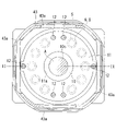
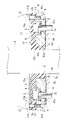
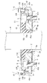
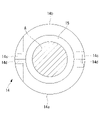
- the insulating cover 10 is preferably elastically deformable, for example, a sponge. As shown in FIGS. 3 to 5, the insulating cover 10 has a ring plate-shaped flat portion 10a arranged inside the base end wall 41 (on the side opposite to the tool mounting surface 2a) and a base of the flat portion 10a. It has a tubular tubular portion 10b extending vertically from the end surface and arranged in the hollow hole 41a, and the hollow hole 10c through which the striatum A passes penetrates from the base end surface of the tubular portion 10b to the tip surface of the flat portion 10a. There is. Both the fixtures 5 and 6 and the hollow hole 41a are covered by such an insulating cover 10.
- the flat portion 10a has an area that covers most of the inner surface of the base end wall 41, and covers all the fixing bolts 5 and all the metal washers 6.
- the flat portion 10a may cover the entire inner surface of the base end wall 41.
- the tubular portion 10b covers the inner peripheral surface of the hollow hole 41a over the entire circumference, and preferably covers the inner peripheral surface of the hollow hole 41a over the entire length in the depth direction.
- the inner diameter of the hollow hole 41a is equal to or larger than the inner diameter of the hollow portion 2d and the inner diameter of the hollow hole 9a, and the peripheral edge portion of the hollow hole 9a is exposed in the hollow hole 41a.
- the inner peripheral surface of the tubular portion 10b (inner peripheral surface of the hollow hole 10c) is arranged radially inside the inner peripheral surface of the hollow portion 2d and the inner peripheral surface of the hollow hole 9a, and the tubular portion 10b is arranged in the hollow hole 41a. It covers the peripheral portion of the hollow hole 9a exposed inside.
- the tubular portion 10b closes the tubular gap between the inner peripheral surface of the hollow hole 41a and the outer peripheral surface of the striatum A.
- the tubular portion 10b has an inner diameter smaller than the outer diameter of the striatum A and an outer diameter larger than the inner diameter of the hollow hole 41a, and is elastically contractable in the radial direction.
- the outer peripheral surface of the tubular portion 10b is in contact with the inner peripheral surface of the hollow hole 41a, and the inner peripheral surface of the tubular portion 10b is in contact with the outer peripheral surface of the striatum A, so that the gap is closed.
- the bracket 1 may further include a holding plate 11 for fixing the insulating cover 10 to the bracket main body 4, and a plurality of fixing bolts (holding plate fixing tools) 12.
- the holding plate 11 is a hard flat plate and may be made of metal.
- the holding plate 11 has a hollow hole 11a that penetrates the holding plate 11 in the thickness direction at a position corresponding to the opening of the hollow portion 2d.
- the base end wall 41 is provided with a plurality of bolt holes 41c to which the fixing bolts 12 are fastened, and the insulating cover 10 and the holding plate 11 are provided with through holes 10d through which the fixing bolts 12 pass at positions corresponding to the bolt holes 41c. , 11b are provided respectively.
- the insulating cover 10 is fixed to the base end wall 41 by fastening the fixing bolt 12 to the bolt hole 41c via the through holes 10d and 11b. If the insulating cover 10 is elastically compressible in the thickness direction, the bracket 1 may further include a tubular spacer 13 arranged in the through hole 10d into which the fixing bolt 12 is inserted.
- the holding plate 11 When the holding plate 11 is larger than the window 43a and it is difficult to pass through the window 43a, the holding plate 11 may be divided into a plurality of members.
- the holding plate 11 may be composed of two semicircular members. According to this configuration, the rigid holding plate 11 can be easily inserted into the bracket main body 4 from the window 43a.
- the tool 3 is attached to the tool mounting surface 4b of the bracket body 4 fixed to the tool mounting surface 2a.
- the striatum A is drawn into the inside of the bracket body 4 from the opening of the hollow portion 2d of the arm member 2b at the tip, and is connected to the tool 3 via the window 42a of the tip wall 42. Will be done.
- the striatum A is pulled out from the inside of the bracket body 4 to the outside of the bracket body 4 via the window 43a of the side wall 43 and is connected to the tool 3.
- the current output from the tool 3 may flow into the bracket body 4.
- the bracket main body 4 and the robot main body 2 are electrically insulated by the insulating members 7 and 8 and the insulating plate 9. Therefore, it is possible to prevent the current from flowing from the bracket main body 4 to the robot main body 2.
- the bracket body 4 having a hollow structure is fixed to the tool mounting surface 2a from the inside by the fixtures 5 and 6, and a line is formed in the bracket body 4 from the opening of the hollow portion 2d on the tool mounting surface 2a via the hollow hole 41a.
- the electrical insulation property may be deteriorated due to the adhesion of foreign matter such as spatter.
- the head of the fixing bolt 5 and the metal washer 6 are exposed from the proximal wall 41 and are located near the surface of the proximal wall 41.
- the inner peripheral surface of the hollow hole 41a is arranged near the inner peripheral surface of the exposed hollow portion 2d.
- the flat portion 10a of the insulating cover 10 covering the fixtures 5 and 6 prevents foreign matter from adhering to the fixtures 5 and 6. This makes it possible to prevent the fixtures 5 and 6 from being electrically connected to the base end wall 41 in the region B.
- the tubular portion 10b of the insulating cover 10 that covers the hollow hole 41a prevents foreign matter from adhering to the inner peripheral surface of the hollow hole 41a and the inner peripheral surface of the hollow portion 2d. This makes it possible to prevent the inner peripheral surface of the hollow hole 41a from being electrically connected to the inner peripheral surface of the hollow portion 2d in the region C.
- the insulating cover 10 is elastically deformable, foreign matter such as spatter is more reliably prevented from entering the regions B and C, and the electrical insulation between the bracket body 4 and the robot body 2 is lowered. This can be prevented more reliably. That is, when the inner surface of the bracket body 4 has unevenness, for example, when the inner surface is a cast surface, the flat portion 10a is deformed along the uneven shape of the inner surface of the base end wall 41, so that the flat portion 10a and the base end wall are formed. It is prevented that a gap is generated between the inner surface of the 41 and the inner surface of the 41.
- the flat portion 10a has an outer diameter larger than the diameter of the circumscribed circles of the plurality of bracket fixtures 5 and 6, a gap may occur between the outer peripheral surface of the flat portion 10a and the bracket fixtures 5 and 6. Be prevented.
- the tubular portion 10b has an inner diameter smaller than the outer diameter of the striatum A and an outer diameter larger than the inner diameter of the hollow hole 41a, between the outer peripheral surface of the tubular portion 10b and the inner peripheral surface of the hollow hole 41a. , And it is prevented that a gap is generated between the inner peripheral surface of the tubular portion 10b and the outer peripheral surface of the striatum A. In this way, the insulating cover 10 can surely close the portion that can be the entrance of the foreign matter into the regions B and C.
- bracket main body 4 is electrically insulated from the robot main body 2, electrical insulation between the bracket main body 4 and the tool 3 is unnecessary. Therefore, the operator can attach / detach the tool 3 to / from the tool mounting surface 4b without requiring additional work for ensuring electrical insulation between the tool 3 and the robot body 2.
- the inflow of current from the tool 3 to the robot body 2 can also be prevented by providing an insulating member between the bracket body 4 and the tool 3.
- the bracket 1 itself is provided with an insulating structure that insulates the bracket 1 from the robot main body 2, and the bracket 1 is fixed to the tool mounting surface 2a by separating only the thin insulating plate 9. ..
- the bracket can also be electrically insulated from the robot body 2 by arranging an insulating member between the tool mounting surface 2a and the bracket and fixing the bracket to the insulating member instead of the tool mounting surface.
- a thick insulating member is required, which increases the amount of offset, the total weight, and the cost.
- the insulating cover 10 has a tubular portion 10b that covers the inner peripheral surface of the hollow hole 41a, but when the flat portion 10a alone can cover the hollow hole 41a, the insulating cover 10 has a tubular portion. It does not necessarily have to have the part 10b. That is, the inner peripheral surface of the flat portion 10a comes into contact with the outer peripheral surface of the striatum A, and the gap between the inner peripheral surface of the hollow hole 41a and the outer peripheral surface of the striatum A is closed by the flat portion 10a. If so, it is possible to prevent foreign matter from entering the hollow hole 41a only by the flat portion 10a. Therefore, in such a case, the tubular portion 10b may not be provided.
- the flat portion 10a of the insulating cover 10 does not have to be in contact with the bracket fixtures 5 and 6. That is, as shown in FIG. 6, a hole 10f having an inner diameter larger than the outer diameter of the bracket fixture 5 or 6 may be opened at a position corresponding to the bracket fixtures 5 and 6 of the flat portion 10a.
- the bracket fixtures 5 and 6 are covered by the insulating cover 10, the holding plate 11, and the base end wall 41, so that the bracket is used. It is possible to prevent foreign matter from adhering to the fixtures 5 and 6.
- the insulating cover 10 does not necessarily have to be elastically deformable.
- the insulating cover 10 may be made of a hard material.
- the insulating cover 10 is an elastically deformable member such as a sponge, the insulating cover 10 can be easily inserted into the bracket main body 4 from the window 43a.
- the insulating cover 10 is not elastically deformable, it may be difficult to pass the insulating cover 10 through the window 43a. Therefore, the insulating cover 10 may be divided into a plurality of members having dimensions capable of passing through the window 43a.
- the bracket 1 may be further provided with an annular clamp 14 arranged in the hollow hole 41a and fixing the striatum A to the tool mounting surface 2a. ..
- the clamp 14 has two semicircular parts 14a and 14b that sandwich the striatum A in the radial direction.
- An elastic body 15 is wound around the outer peripheral surface of the striatum A, and the elastic body 15 is arranged between the striatum A and the clamp 14.
- the two parts 14a and 14b are in close contact with and fixed to the outer peripheral surface of the striatum A with the elastic body 15 separated from the two parts 14a and 14b.
- the fixing of the parts 14a and 14b is performed, for example, by screwing the bolt 14c into the bolt holes 14d of the parts 14a and 14b.
- the clamp 14 is fixed to the tool mounting surface 2a by a bolt (not shown).
- the insulating cover 10 does not have the tubular portion 10b. You may.
- the flat portion 10a extends radially inward from the inner peripheral surface of the clamp 14 and covers the entire inside of the clamp 14. According to this configuration, by fixing the striatum A in the hollow hole 41a of the base end wall 41, the movement of the striatum A in the bracket main body 4 can be suppressed.
- the holding plate 11, the fixing bolt 12, and the spacer 13 are used as the fixing means for fixing the insulating cover 10 to the base end wall 41 of the bracket main body 4, but the fixing means is the insulating cover 10. It can be changed as appropriate according to the material and the like.
- the insulating cover 10 may be fixed to the base end wall 41 by a plurality of fixing means. In one example, when the insulating cover 10 is a rubber part or a resin part having high rigidity, the insulating cover 10 is based on using only the fixing bolt (cover fixing tool) 12 without using the holding plate 11 and the spacer 13. It may be fixed to the end wall 41. If necessary, a washer may be arranged between the fixing bolt 12 and the insulating cover 10.
- the insulating cover 10 has a recess 10e into which the head of the fixing bolt 5 fits in the surface on the base end wall 41 side, as shown in FIGS. 4 and 7, and the head of the fixing bolt 5.
- the insulating cover 10 may be fixed to the base end wall 41 by fitting the portion and the recess 10e.
- the insulating cover 10 may be adhered to the inner surface of the base end wall 41 with an adhesive or the like.
- the holding plate 11 may have a striatum fixing portion 11c for fixing the striatum A to the holding plate 11.
- the striatum fixing portion 11c is, for example, a flat plate-shaped member, and is arranged outside the bracket main body 4.
- the striatum A is fixed to the striatum fixing portion 11c using, for example, a band.
- the holding plate 11 of FIG. 10 has two semicircular portions 11d arranged in the bracket main body 4 and a striatal fixing portion 11c connected to one semicircular portion 11d, and the other semicircular portion 11c. Is omitted.
- the striatum A When the striatum A is movable with respect to the bracket body 4 due to the operation of the robot body 2, the striatum A comes into contact with the casting surface of the bracket body 4 and covers the outside of the striatum A. May be hurt.
- the striatum fixing portion 11c By fixing the striatum A to the holding plate 11 by the striatum fixing portion 11c, it is possible to limit the movement of the striatum A and prevent the striatum A from being damaged.
- the bracket 1 is used to attach the hollow or solid tool 3 to the hollow arm member 2b, but instead, the hollow welding tool 3 is attached to the non-hollow arm member 2b. May be used to attach.
- the bracket 1 may be provided as part of the welding device. That is, the welding device includes a bracket 1 and a hollow welding tool 3.
- the hollow welding tool 3 is attached to the robot mounting surface 4a through which the hollow hole 41a opens by the bracket fixtures 5 and 6, and the welding tool 3 and the bracket body 4 are electrically insulated by the insulating members 7 and 8. Weld. At least one striatum is wired between the hollow portion of the welding tool 3 and the inside of the bracket body 4 via the hollow hole 41a.
- the bracket 1 is attached to the tool mounting surface 2a of the arm member 2b which is not hollow in the tool mounting surface 4b. In this case, the tip wall 42 does not have to have the window 42a.
- the bracket 1 may be provided as a part of a robot system for welding. That is, the robot system includes a robot 20 having a bracket 1 and a robot body 2, and a welding device having a welding tool 3 such as a welding gun. The welding device is fixed to the tip of the robot body 2 with the bracket 1 interposed therebetween.
Landscapes
- Engineering & Computer Science (AREA)
- Robotics (AREA)
- Mechanical Engineering (AREA)
- Manipulator (AREA)
- Electric Cable Arrangement Between Relatively Moving Parts (AREA)
- Installation Of Indoor Wiring (AREA)
Abstract
Description
線条体をブラケットの内部から外部へ引き出すことができるようにブラケットの内部空間はブラケットの外部に開放されている。したがって、スパッタ等の電気絶縁性が空気よりも低い異物が、ブラケットの外側から内側へ侵入してブラケット内の部品やアーム部材の中空部に付着し、ブラケットとロボット本体との間の電気絶縁性の低下を引き起こす可能性がある。
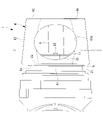
図1に示されるように、ロボット20は、ロボット本体2と、ロボット本体2のツール取付面2aに取り付け可能である中空構造のブラケット1と、を備える産業用のロボットである。
ツール取付面2aとブラケット本体4との間には、電気絶縁性の絶縁プレート9が配置される。絶縁プレート9は、中空部2dの開口と対向する位置に絶縁プレート9を厚さ方向に貫通する中空穴9aを有する。絶縁プレート9は、ロボット本体2の一部またはブラケット1の一部として提供されてもよい。絶縁プレート9は、絶縁部材7と一体であってもよい。
基端壁41は、中空部2dの開口と対向する位置に基端壁41を厚さ方向に貫通する中空穴41aを有し、中空穴41a,9aを経由してアーム部材2bの中空部2dとブラケット1の内部空間とが連通する。線条体Aは、中空部2dの開口から中空穴9a,41aを通ってブラケット1の内部へ配線される。
側壁43は、側壁43を厚さ方向に貫通し線条体Aが通過可能である少なくとも1つの窓43aを有する。ツール3が中空構造でない場合、線条体Aは、窓43aを経由してブラケット1の外側に引き出されツール3に接続される。
絶縁部材は、筒状の絶縁スリーブ7および円環板状の絶縁ワッシャ8であり、樹脂等の電気絶縁材料から形成される。絶縁スリーブ7は、通し穴41bの内面と固定ボルト5の外面との間に配置され、絶縁ワッシャ8は、基端壁41の内面と金属ワッシャ6との間に配置される。絶縁スリーブ7および絶縁ワッシャ8によって、固定ボルト5および金属ワッシャ6がブラケット本体4から電気的に絶縁され、ブラケット本体4から固定ボルト5および金属ワッシャ6を経由してロボット本体2に電流が流れ込むことが防止される。
押さえ板11は硬質の平板であり、金属製であってもよい。押さえ板11は、中空部2dの開口と対応する位置に、押さえ板11を厚さ方向に貫通する中空穴11aを有する。
ツール3は、ツール取付面2aに固定されたブラケット本体4のツール取付面4bに取り付けられる。ツール3が中空構造である場合、線条体Aは、先端のアーム部材2bの中空部2dの開口からブラケット本体4の内部に引き込まれ、先端壁42の窓42aを経由してツール3に接続される。ツール3が中空構造でない場合、線条体Aは、ブラケット本体4の内部から側壁43の窓43aを経由してブラケット本体4の外部に引き出されツール3に接続される。
また、中空穴41aを覆う絶縁カバー10の筒部10bによって、中空穴41aの内周面および中空部2dの内周面に異物が付着することが防止される。これにより、領域Cにおいて中空穴41aの内周面が中空部2dの内周面と電気的に接続されてしまうことを防止することができる。
すなわち、ブラケット本体4の内面が凹凸を有する場合、例えば内面が鋳肌である場合、平坦部10aが基端壁41の内面の凹凸形状に沿って変形することによって、平坦部10aと基端壁41の内面との間に隙間が生じることが防止される。また、平坦部10aが複数のブラケット固定具5,6の外接円の直径よりも大きな外径を有する場合、平坦部10aの外周面とブラケット固定具5,6との間に隙間が生じることが防止される。また、筒部10bが、線条体Aの外径よりも小さい内径および中空穴41aの内径よりも大きい外径を有する場合、筒部10bの外周面と中空穴41aの内周面との間、および、筒部10bの内周面と線条体Aの外周面との間に隙間が生じることが防止される。このように、領域B,Cへの異物の侵入の入り口となり得る箇所を絶縁カバー10によって確実に塞ぐことができる。
ツール3からロボット本体2への電流の流れ込みは、ブラケット本体4とツール3との間に絶縁部材を設けることによっても防止することができる。しかし、この場合、ツール3をツール取付面4bに着脱する際に、絶縁部材の着脱も必要となり、取り扱う部品の点数および作業が増える。
ツール取付面2aとブラケットとの間に絶縁部材を配置し、ブラケットを、ツール取付面ではなく絶縁部材に固定することによっても、ブラケットをロボット本体2から電気的に絶縁することができる。しかし、この場合、厚い絶縁部材が必要となり、オフセット量、総重量およびコストが増大する。
すなわち、平坦部10aの内周面が線条体Aの外周面と接触し、中空穴41aの内周面と線条体Aの外周面との間の隙間が平坦部10aによって塞がれている場合、平坦部10aのみで中空穴41aへの異物の侵入を防ぐことができる。したがって、このような場合には、筒部10bが設けられていなくてもよい。
絶縁カバー10がスポンジのように弾性変形可能な部材である場合、窓43aからブラケット本体4内に絶縁カバー10を容易に挿入することができる。一方、絶縁カバー10が弾性変形可能ではない場合、絶縁カバー10を窓43aに通すことが困難になり得る。したがって、絶縁カバー10は、窓43aを通過可能な寸法の複数の部材に分割されていてもよい。
クランプ14は、図8に示されるように、線条体Aを径方向に挟む2つの半円弧状の部品14a,14bを有する。線条体Aの外周面には弾性体15が巻かれ、線条体Aとクランプ14との間に弾性体15が配置される。2つの部品14a,14bは、弾性体15を隔てて線条体Aの外周面に密着し固定される。部品14a,14bの固定は、例えば、ボルト14cを部品14a,14bのボルト穴14d内にねじ込むことによって行われる。クランプ14は、図示しないボルトによってツール取付面2aに固定される。
この構成によれば、基端壁41の中空穴41aにおいて線条体Aを固定することによって、ブラケット本体4内での線条体Aの移動を抑制することができる。
一例において、絶縁カバー10が高い剛性を有するゴム部品または樹脂部品である場合、絶縁カバー10は、押さえ板11およびスペーサ13を使用せず、固定ボルト(カバー固定具)12のみを使用して基端壁41に固定されてもよい。必要に応じて、固定ボルト12と絶縁カバー10の間にワッシャを配置してもよい。
他の例において、絶縁カバー10が、接着剤等によって基端壁41の内面に接着されてもよい。
線条体固定部11cは、例えば平板状の部材であり、ブラケット本体4の外側に配置される。線条体Aは、例えば、バンドを使用して線条体固定部11cに固定される。図10の押さえ板11は、ブラケット本体4内に配置される2つの半円部11dと、一方の半円部11dに接続された線条体固定部11cとを有し、他方の半円部の図示は省略されている。
中空の溶接ツール3は、中空穴41aが開口するロボット取付面4aにブラケット固定具5,6によって取り付けられ、溶接ツール3とブラケット本体4との間が絶縁部材7,8によって電気的に絶縁される。少なくとも1本の線条体が、中空穴41aを経由して溶接ツール3の中空部とブラケット本体4の内部との間で配線される。ブラケット1は、ツール取付面4bにおいて中空ではないアーム部材2bのツール取付面2aに取り付けられる。この場合、先端壁42は窓42aを有していなくてもよい。
2 ロボット本体
2a ツール取付面
2b 先端のアーム部材
2d 中空部
3 ツール、溶接ツール
4 ブラケット本体
41a 中空穴
5 ブラケット固定具、固定ボルト
6 ブラケット固定具、金属ワッシャ
7 絶縁部材、絶縁スリーブ
8 絶縁部材、絶縁ワッシャ
10 絶縁カバー
10a 平坦部
10b 筒部
10e 凹部
11 押さえ板
11c 線条体固定部
12 押さえ板固定具、カバー固定具、固定ボルト
14 クランプ
20 ロボット
A 線条体
Claims (12)
- 中空構造のブラケット用の電気絶縁性の絶縁カバーであって、前記ブラケットが、中空のアーム部材のツール取付面に取り付けられ、該ツール取付面上の開口を経由して前記アーム部材内の中空部から前記ブラケットの内部へ線条体を通す中空穴を有し、
前記ブラケットの内部に配置され、
前記ブラケットを前記ツール取付面に固定するブラケット固定具、および、前記ブラケットの前記中空穴の両方を覆う、絶縁カバー。 - 前記ブラケットの前記ツール取付面側の内面上に配置される板状の平坦部を有し、
前記絶縁カバーが弾性変形可能である、請求項1に記載の絶縁カバー。 - 中空のアーム部材のツール取付面に取り付けられる中空構造のブラケット本体であって、前記ツール取付面上の開口を経由して前記アーム部材内の中空部から前記ブラケット本体の内部へ線条体を通す中空穴を有する、ブラケット本体と、
該ブラケット本体を前記ブラケット本体の内側から前記ツール取付面に固定するブラケット固定具と、
該ブラケット固定具と前記ブラケット本体との間に配置され、前記ブラケット固定具と前記ブラケット本体との間を電気的に絶縁する絶縁部材と、
前記ブラケット本体の内部に配置される請求項1または請求項2に記載の絶縁カバーとを備える、ブラケット。 - 前記中空穴内に配置され、前記線条体を前記ツール取付面に対して固定する環状のクランプを備える請求項3に記載のブラケット。
- 前記絶縁カバーの前記ツール取付面とは反対側に配置される押さえ板と、
該押さえ板を前記ブラケット本体に固定する押さえ板固定具とを備える、請求項3または請求項4に記載のブラケット。 - 前記絶縁カバーを前記ブラケット本体に固定するカバー固定具を備える、請求項3から請求項5のいずれかに記載のブラケット。
- 前記絶縁カバーは、前記ブラケット固定具の頭部が嵌合する凹部を有し、前記頭部と前記凹部との嵌合によって前記ブラケット本体に固定される、請求項3から請求項6のいずれかに記載のブラケット。
- 前記絶縁カバーが、前記ブラケット本体に接着される、請求項3から請求項7のいずれかに記載のブラケット。
- 前記押さえ板が、前記線条体を押さえ板に固定する線条体固定部を有する、請求項5に記載のブラケット。
- 少なくとも1つのアーム部材を有し、先端のアーム部材が中空であるロボット本体と、
請求項3から請求項9のいずれかに記載のブラケットとを備えるロボット。 - 請求項3から請求項9のいずれかに記載のブラケットと、
中空の溶接ツールとを備え、
該溶接ツールは、前記中空穴が開口する前記ブラケット本体の外面に取り付けられ、少なくとも1本の線条体が、前記中空穴を経由して前記溶接ツールの中空部と前記ブラケットの内部との間で配線される、溶接装置。 - 請求項10に記載のロボットと、
前記ロボット本体の先端に前記ブラケットを隔てて固定されるツールとを備えるロボットシステム。
Priority Applications (4)
| Application Number | Priority Date | Filing Date | Title |
|---|---|---|---|
| US18/253,269 US12325126B2 (en) | 2020-12-08 | 2021-12-03 | Insulating cover, bracket, robot, welding device, and robot system |
| DE112021005058.3T DE112021005058T5 (de) | 2020-12-08 | 2021-12-03 | Isolierabdeckung, halter, roboter, schweissvorrichtung und robotersystem |
| CN202180080821.9A CN116529038B (zh) | 2020-12-08 | 2021-12-03 | 绝缘罩、托架、机器人、焊接装置以及机器人系统 |
| JP2022568240A JP7453419B2 (ja) | 2020-12-08 | 2021-12-03 | 絶縁カバー、ブラケット、ロボット、溶接装置およびロボットシステム |
Applications Claiming Priority (2)
| Application Number | Priority Date | Filing Date | Title |
|---|---|---|---|
| JP2020203508 | 2020-12-08 | ||
| JP2020-203508 | 2020-12-08 |
Publications (1)
| Publication Number | Publication Date |
|---|---|
| WO2022124208A1 true WO2022124208A1 (ja) | 2022-06-16 |
Family
ID=81974575
Family Applications (1)
| Application Number | Title | Priority Date | Filing Date |
|---|---|---|---|
| PCT/JP2021/044377 Ceased WO2022124208A1 (ja) | 2020-12-08 | 2021-12-03 | 絶縁カバー、ブラケット、ロボット、溶接装置およびロボットシステム |
Country Status (6)
| Country | Link |
|---|---|
| US (1) | US12325126B2 (ja) |
| JP (1) | JP7453419B2 (ja) |
| CN (1) | CN116529038B (ja) |
| DE (1) | DE112021005058T5 (ja) |
| TW (1) | TWI881191B (ja) |
| WO (1) | WO2022124208A1 (ja) |
Citations (2)
| Publication number | Priority date | Publication date | Assignee | Title |
|---|---|---|---|---|
| US5515599A (en) * | 1994-05-03 | 1996-05-14 | Best; Norman D. | Apparatus for processing small parts utilizing a robot and an array of tools mounted on the outer robot arm |
| JP2004306072A (ja) * | 2003-04-04 | 2004-11-04 | Daihen Corp | アーク溶接ロボットにおける溶接ワイヤ等の供給機構 |
Family Cites Families (16)
| Publication number | Priority date | Publication date | Assignee | Title |
|---|---|---|---|---|
| JPS62142083A (ja) | 1985-12-16 | 1987-06-25 | Mitsubishi Electric Corp | 産業用ロボツト装置 |
| JPH0847886A (ja) | 1994-08-04 | 1996-02-20 | Fanuc Ltd | 産業用ロボットの中空手首 |
| SE508533C2 (sv) * | 1997-02-10 | 1998-10-12 | Asea Brown Boveri | Industrirobot med en vridskiva som är elektriskt isolerad från industriroboten samt ett förfarande för tillverkning av sådan robot |
| JPH11114873A (ja) * | 1997-10-20 | 1999-04-27 | Fanuc Ltd | 産業用ロボット |
| SE516877C2 (sv) * | 1999-12-01 | 2002-03-19 | Abb Ab | Ett förfarande och ett vridorgan för dragning av ett kablage för en industrirobot |
| KR100415197B1 (ko) * | 2001-05-18 | 2004-01-16 | 고려용접봉 주식회사 | 와이어 스풀용 절연 커버 |
| SE522933C2 (sv) * | 2001-08-02 | 2004-03-16 | Abb Ab | Industrirobot utrustad med ett löstagbart kablage |
| JP3900417B2 (ja) * | 2002-03-25 | 2007-04-04 | 株式会社ジェイテクト | 摺動接点 |
| JP3814241B2 (ja) * | 2002-10-31 | 2006-08-23 | ファナック株式会社 | 産業用ロボット |
| JP5344315B2 (ja) | 2010-11-04 | 2013-11-20 | 株式会社安川電機 | ロボットの手首構造及びロボット |
| JP5383846B2 (ja) | 2012-03-27 | 2014-01-08 | ファナック株式会社 | 産業用ロボットの手首先端部における線条体案内機構部 |
| JP5568121B2 (ja) * | 2012-11-12 | 2014-08-06 | ファナック株式会社 | 産業用ロボットの手首先端部における線条体案内装置および産業用ロボット |
| JP6538498B2 (ja) * | 2015-09-15 | 2019-07-03 | ファナック株式会社 | 中空の可動要素と防水構造とを有する手首を備えるロボット |
| CN108856996B (zh) * | 2018-07-18 | 2021-06-29 | 安徽瑞祥工业有限公司 | 一种铝合金焊接夹具中的绝缘装置及其使用方法 |
| JP6923572B2 (ja) * | 2019-01-24 | 2021-08-18 | ファナック株式会社 | 取付ブラケット |
| JP7458864B2 (ja) * | 2020-04-06 | 2024-04-01 | 川崎重工業株式会社 | 絶縁ユニット、ロボット及び絶縁ユニットの取り付け方法 |
-
2021
- 2021-12-03 US US18/253,269 patent/US12325126B2/en active Active
- 2021-12-03 CN CN202180080821.9A patent/CN116529038B/zh active Active
- 2021-12-03 JP JP2022568240A patent/JP7453419B2/ja active Active
- 2021-12-03 TW TW110145360A patent/TWI881191B/zh active
- 2021-12-03 WO PCT/JP2021/044377 patent/WO2022124208A1/ja not_active Ceased
- 2021-12-03 DE DE112021005058.3T patent/DE112021005058T5/de active Pending
Patent Citations (2)
| Publication number | Priority date | Publication date | Assignee | Title |
|---|---|---|---|---|
| US5515599A (en) * | 1994-05-03 | 1996-05-14 | Best; Norman D. | Apparatus for processing small parts utilizing a robot and an array of tools mounted on the outer robot arm |
| JP2004306072A (ja) * | 2003-04-04 | 2004-11-04 | Daihen Corp | アーク溶接ロボットにおける溶接ワイヤ等の供給機構 |
Also Published As
| Publication number | Publication date |
|---|---|
| JPWO2022124208A1 (ja) | 2022-06-16 |
| JP7453419B2 (ja) | 2024-03-19 |
| TWI881191B (zh) | 2025-04-21 |
| CN116529038A (zh) | 2023-08-01 |
| TW202227241A (zh) | 2022-07-16 |
| DE112021005058T5 (de) | 2023-12-28 |
| US20240017398A1 (en) | 2024-01-18 |
| CN116529038B (zh) | 2026-03-10 |
| US12325126B2 (en) | 2025-06-10 |
Similar Documents
| Publication | Publication Date | Title |
|---|---|---|
| US9806457B2 (en) | Articulated robot with connection member for connecting wire body arranged on arm | |
| KR101737900B1 (ko) | 건설기계용 유압배관 고정장치 | |
| US8893577B2 (en) | Umbilical member arrangement unit of robot arm section | |
| EP1938930B1 (en) | Industrial robot with tubular member for a cable harness | |
| CN106514688B (zh) | 机器人 | |
| EP1666218B1 (en) | Guiding device for an umbilical member of a robot and a robot having the guiding device | |
| JP2013511011A (ja) | パイプまたはダクト用のクリップ | |
| US20160205816A1 (en) | Composite cable mounted in industrial robot | |
| JP2008275059A (ja) | ケーブル類保護案内装置 | |
| US20200056531A1 (en) | Exhaust System Isolator Mount With Anti-Rotation Feature | |
| US20110147540A1 (en) | Mounting Arrangement For Connecting Components To A Machine | |
| JP2021079494A (ja) | ロボット用ケーシングおよびロボット | |
| WO2022124208A1 (ja) | 絶縁カバー、ブラケット、ロボット、溶接装置およびロボットシステム | |
| US20070273179A1 (en) | Joining Area for Attaching an Add-On Piece to a Vehicle Body | |
| EP1100149A2 (en) | Attachment device with cap | |
| KR101858536B1 (ko) | 로봇용 용접토치 | |
| JP7110782B2 (ja) | アタッチメント、ロボット用のジャケット | |
| WO2023188157A1 (ja) | ブラケット、ロボット、溶接装置およびロボットシステム | |
| TW202231425A (zh) | 機器人 | |
| JP2003159689A (ja) | 中空穴手首を有する産業用ロボットのアーム装置 | |
| EP4487972B1 (en) | Fume extractor attachment for a welding torch, and fume extractor system with such attachment | |
| US20020035413A1 (en) | Industrial robot | |
| JPH11114873A (ja) | 産業用ロボット | |
| CN211028703U (zh) | 一种机器人枪览保护装置 | |
| WO2018081940A1 (en) | Robot base unit, robot system and method of manufacturing robot base unit |
Legal Events
| Date | Code | Title | Description |
|---|---|---|---|
| 121 | Ep: the epo has been informed by wipo that ep was designated in this application |
Ref document number: 21903312 Country of ref document: EP Kind code of ref document: A1 |
|
| ENP | Entry into the national phase |
Ref document number: 2022568240 Country of ref document: JP Kind code of ref document: A |
|
| WWE | Wipo information: entry into national phase |
Ref document number: 18253269 Country of ref document: US |
|
| WWE | Wipo information: entry into national phase |
Ref document number: 112021005058 Country of ref document: DE |
|
| WWE | Wipo information: entry into national phase |
Ref document number: 202180080821.9 Country of ref document: CN |
|
| 122 | Ep: pct application non-entry in european phase |
Ref document number: 21903312 Country of ref document: EP Kind code of ref document: A1 |
|
| WWG | Wipo information: grant in national office |
Ref document number: 18253269 Country of ref document: US |