WO2022124145A1 - パンツ型吸収性物品及びその製造方法 - Google Patents
パンツ型吸収性物品及びその製造方法 Download PDFInfo
- Publication number
- WO2022124145A1 WO2022124145A1 PCT/JP2021/043915 JP2021043915W WO2022124145A1 WO 2022124145 A1 WO2022124145 A1 WO 2022124145A1 JP 2021043915 W JP2021043915 W JP 2021043915W WO 2022124145 A1 WO2022124145 A1 WO 2022124145A1
- Authority
- WO
- WIPO (PCT)
- Prior art keywords
- sheet
- laminated
- pants
- absorbent article
- exterior body
- Prior art date
- Legal status (The legal status is an assumption and is not a legal conclusion. Google has not performed a legal analysis and makes no representation as to the accuracy of the status listed.)
- Ceased
Links
Images








Classifications
-
- A—HUMAN NECESSITIES
- A61—MEDICAL OR VETERINARY SCIENCE; HYGIENE
- A61F—FILTERS IMPLANTABLE INTO BLOOD VESSELS; PROSTHESES; DEVICES PROVIDING PATENCY TO, OR PREVENTING COLLAPSING OF, TUBULAR STRUCTURES OF THE BODY, e.g. STENTS; ORTHOPAEDIC, NURSING OR CONTRACEPTIVE DEVICES; FOMENTATION; TREATMENT OR PROTECTION OF EYES OR EARS; BANDAGES, DRESSINGS OR ABSORBENT PADS; FIRST-AID KITS
- A61F13/00—Bandages or dressings; Absorbent pads
- A61F13/15—Absorbent pads, e.g. sanitary towels, swabs or tampons for external or internal application to the body; Supporting or fastening means therefor; Tampon applicators
-
- A—HUMAN NECESSITIES
- A61—MEDICAL OR VETERINARY SCIENCE; HYGIENE
- A61F—FILTERS IMPLANTABLE INTO BLOOD VESSELS; PROSTHESES; DEVICES PROVIDING PATENCY TO, OR PREVENTING COLLAPSING OF, TUBULAR STRUCTURES OF THE BODY, e.g. STENTS; ORTHOPAEDIC, NURSING OR CONTRACEPTIVE DEVICES; FOMENTATION; TREATMENT OR PROTECTION OF EYES OR EARS; BANDAGES, DRESSINGS OR ABSORBENT PADS; FIRST-AID KITS
- A61F13/00—Bandages or dressings; Absorbent pads
- A61F13/15—Absorbent pads, e.g. sanitary towels, swabs or tampons for external or internal application to the body; Supporting or fastening means therefor; Tampon applicators
- A61F13/45—Absorbent pads, e.g. sanitary towels, swabs or tampons for external or internal application to the body; Supporting or fastening means therefor; Tampon applicators characterised by the shape
- A61F13/49—Absorbent pads, e.g. sanitary towels, swabs or tampons for external or internal application to the body; Supporting or fastening means therefor; Tampon applicators characterised by the shape specially adapted to be worn around the waist, e.g. diapers, nappies
-
- A—HUMAN NECESSITIES
- A61—MEDICAL OR VETERINARY SCIENCE; HYGIENE
- A61F—FILTERS IMPLANTABLE INTO BLOOD VESSELS; PROSTHESES; DEVICES PROVIDING PATENCY TO, OR PREVENTING COLLAPSING OF, TUBULAR STRUCTURES OF THE BODY, e.g. STENTS; ORTHOPAEDIC, NURSING OR CONTRACEPTIVE DEVICES; FOMENTATION; TREATMENT OR PROTECTION OF EYES OR EARS; BANDAGES, DRESSINGS OR ABSORBENT PADS; FIRST-AID KITS
- A61F13/00—Bandages or dressings; Absorbent pads
- A61F13/15—Absorbent pads, e.g. sanitary towels, swabs or tampons for external or internal application to the body; Supporting or fastening means therefor; Tampon applicators
- A61F13/45—Absorbent pads, e.g. sanitary towels, swabs or tampons for external or internal application to the body; Supporting or fastening means therefor; Tampon applicators characterised by the shape
- A61F13/49—Absorbent pads, e.g. sanitary towels, swabs or tampons for external or internal application to the body; Supporting or fastening means therefor; Tampon applicators characterised by the shape specially adapted to be worn around the waist, e.g. diapers, nappies
- A61F13/494—Absorbent pads, e.g. sanitary towels, swabs or tampons for external or internal application to the body; Supporting or fastening means therefor; Tampon applicators characterised by the shape specially adapted to be worn around the waist, e.g. diapers, nappies characterised by edge leakage prevention means
-
- A—HUMAN NECESSITIES
- A61—MEDICAL OR VETERINARY SCIENCE; HYGIENE
- A61F—FILTERS IMPLANTABLE INTO BLOOD VESSELS; PROSTHESES; DEVICES PROVIDING PATENCY TO, OR PREVENTING COLLAPSING OF, TUBULAR STRUCTURES OF THE BODY, e.g. STENTS; ORTHOPAEDIC, NURSING OR CONTRACEPTIVE DEVICES; FOMENTATION; TREATMENT OR PROTECTION OF EYES OR EARS; BANDAGES, DRESSINGS OR ABSORBENT PADS; FIRST-AID KITS
- A61F13/00—Bandages or dressings; Absorbent pads
- A61F13/15—Absorbent pads, e.g. sanitary towels, swabs or tampons for external or internal application to the body; Supporting or fastening means therefor; Tampon applicators
- A61F13/45—Absorbent pads, e.g. sanitary towels, swabs or tampons for external or internal application to the body; Supporting or fastening means therefor; Tampon applicators characterised by the shape
- A61F13/49—Absorbent pads, e.g. sanitary towels, swabs or tampons for external or internal application to the body; Supporting or fastening means therefor; Tampon applicators characterised by the shape specially adapted to be worn around the waist, e.g. diapers, nappies
- A61F13/496—Absorbent pads, e.g. sanitary towels, swabs or tampons for external or internal application to the body; Supporting or fastening means therefor; Tampon applicators characterised by the shape specially adapted to be worn around the waist, e.g. diapers, nappies in the form of pants or briefs
-
- A—HUMAN NECESSITIES
- A61—MEDICAL OR VETERINARY SCIENCE; HYGIENE
- A61F—FILTERS IMPLANTABLE INTO BLOOD VESSELS; PROSTHESES; DEVICES PROVIDING PATENCY TO, OR PREVENTING COLLAPSING OF, TUBULAR STRUCTURES OF THE BODY, e.g. STENTS; ORTHOPAEDIC, NURSING OR CONTRACEPTIVE DEVICES; FOMENTATION; TREATMENT OR PROTECTION OF EYES OR EARS; BANDAGES, DRESSINGS OR ABSORBENT PADS; FIRST-AID KITS
- A61F13/00—Bandages or dressings; Absorbent pads
- A61F13/15—Absorbent pads, e.g. sanitary towels, swabs or tampons for external or internal application to the body; Supporting or fastening means therefor; Tampon applicators
- A61F13/51—Absorbent pads, e.g. sanitary towels, swabs or tampons for external or internal application to the body; Supporting or fastening means therefor; Tampon applicators characterised by the outer layers of the pads
Definitions
- the present invention relates to a pants-type absorbent article and a method for producing the same.
- the pants-type absorbent article generally comprises an absorbent body having an absorbent core and an exterior body joined to the absorbent body, and is of a pants-type having a waist opening and a pair of leg openings. It has a morphology.
- the exterior body of the pants-type absorbent article is provided with an elastic member for the purpose of imparting elasticity to the exterior body, and is composed of a laminated body of a plurality of sheets for holding and fixing the elastic member.
- Patent Document 1 describes a pants-type absorbent article in which the exterior body is composed of three sheets.
- the exterior body of the absorbent article includes a step of intermittently welding the first sheet member and the second sheet member by a plurality of welding portions, and a surface of the second sheet member opposite to the first sheet member.
- the exterior body has a laminated portion in which the first sheet member, the second sheet member, and the third sheet member are laminated in order from the skin side to the non-skin side in the thickness direction of the exterior body. It is formed. According to the pants-type absorbent article having such a configuration, it is described in the same document that the exterior body can be reinforced without breaking the soft and elastic member.
- the present invention has a vertical direction extending from the ventral side of the wearer to the dorsal side via the crotch portion and a lateral direction orthogonal to the vertical direction, and the crotch portion arranged in the crotch portion and the crotch portion.
- the present invention relates to a pants-type absorbent article in which a pair of side seals, a waist opening and a pair of leg openings are formed.
- the exterior body having an open edge portion along the leg opening has a laminated portion including a first elastic sheet, a non-stretchable second sheet, and a non-stretchable third sheet, at least in part thereof. It is preferably composed of.
- the first sheet is joined to the second sheet in the stretched state
- the third sheet is joined to the first sheet or the second sheet in the stretched state of the first sheet.
- the laminated portion in the opening edge portion has a shape that is curved toward the non-skin facing surface side with the opening end of the leg opening as a free end.
- the present invention has a vertical direction extending from the ventral side of the wearer to the dorsal side through the crotch portion and a lateral direction orthogonal to the vertical direction, and the crotch portion arranged in the crotch portion and the crotch lower portion. It is divided into a ventral part arranged on the ventral side of the wearer and a dorsal part arranged on the dorsal side of the wearer rather than the inseam, and is absorbent including an absorbent core that absorbs and retains body fluid.
- a main body and an exterior body arranged on the non-skin facing surface side of the absorbent main body are provided, and both side portions of the exterior body along the vertical direction in each of the ventral side portion and the dorsal side portion are joined to each other.
- the present invention relates to a method for manufacturing a pants-type absorbent article, wherein a pair of side seal portions, a waist opening portion and a pair of leg openings are formed. While transporting the elastic first raw fabric in one direction in the stretched state, it is joined to the non-stretchable second raw fabric transported in the same direction, and then the stretched state of the first raw fabric is obtained.
- the non-stretchable third raw fabric transported along the same direction is joined to the first raw fabric or the second raw fabric, and has a laminated portion in which these three raw fabrics are laminated.
- An absorbent main body arranging step of intermittently arranging the absorbent main body along the transport direction on one surface of the original fabric of the exterior body which is conveyed along one direction while maintaining the stretched state of the first raw fabric. It is preferable to have.
- the laminated sheet cutting step it is preferable to cut the laminated sheet of the exterior body so that the laminated portion is at least present in the planned cutting portion.
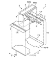
- FIG. 1 is a perspective view schematically showing a pants-type diaper which is an embodiment of the pants-type absorbent article of the present invention.
- FIG. 2 is a developed plan view schematically showing a skin-facing surface (arrangement side of the absorbent body) in the unfolded and stretched state of the diaper shown in FIG.
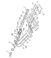
- FIG. 3 is a schematic exploded perspective view of the diaper shown in FIG.
- FIG. 4 is a partially cutaway perspective view schematically showing an example of the first sheet according to the present invention.
- FIG. 5 is a schematic cross-sectional view taken along the line VV of the diaper shown in FIG. 6 (a) and 6 (b) are schematic views showing an arrangement pattern of a joint portion for joining the first sheet and the second sheet constituting the exterior body of the pants-type diaper shown in FIG.
- FIG. 7 is a perspective view schematically showing the manufacturing process of the diaper shown in FIG.
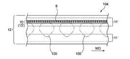
- FIG. 8 is an enlarged view of a main part of the laminated sheet manufacturing process in the manufacturing process shown in FIG. 7.
- FIG. 9 is an enlarged view of a main part of the laminated sheet cutting process in the manufacturing process shown in FIG. 7.
- FIG. 10 is a diagram showing the shape of a planned cutting portion in the laminated sheet cutting step in the manufacturing process shown in FIG. 7.
- FIG. 11 is a schematic diagram showing a process following the manufacturing process shown in FIG. 7.
- FIG. 12 is an enlarged view of a main part (corresponding to FIG. 8) showing another embodiment of the laminated sheet manufacturing process in the manufacturing process shown in FIG. 7.
- FIG. 13 is an enlarged view of a main part (corresponding to FIG. 8) showing still another embodiment of the laminated sheet manufacturing process in the manufacturing process shown in FIG. 7.
- FIG. 14 is an enlarged view of a main part (corresponding to FIG. 8) showing still another embodiment of the laminated sheet
- the pants-type absorbent article When the pants-type absorbent article is manufactured by the method described in Patent Document 1, it may be possible to soften the exterior body itself, but the fit with the wearer's body at the leg opening in the pants-type absorbent article. There is room for improvement in terms of sex. The reason for this is that the fit to the wearer's body at the leg opening is exclusively achieved by the contraction of the thread-like elastic members arranged along the leg opening, and the fit is improved by such means. Because there is a limit to. Further, when the pants-type absorbent article is manufactured by the method described in Patent Document 1, it is possible to prevent the occurrence of discomfort caused by the edge of the exterior body, for example, the edge of the leg opening coming into contact with the wearer's skin. It's not easy.
- a leg opening is generally formed by cutting a laminated sheet of an exterior body, and the cut portion remains as it is. This is because no special treatment is applied to reduce the discomfort when it comes into contact with the wearer's skin.
- the present invention relates to a pants-type absorbent article and a method for producing the same, which can eliminate the drawbacks of the above-mentioned prior art.
- the pants-type absorbent article of the present invention has a vertical direction (direction indicated by reference numeral "X” in the figure) corresponding to the front-back direction of the wearer, that is, a direction extending from the ventral side to the back side via the crotch portion, and the vertical direction. It has a lateral direction (direction indicated by reference numeral “Y” in the figure) orthogonal to the direction.
- the vertical direction is the vertical direction of the pants-type absorbent article or the direction along the vertical direction of its constituent members (for example, the absorbent body), and the horizontal direction is the pants-type absorbent article.
- the pants-type absorbent article of the present invention is arranged in the crotch portion of the wearer and includes the inseam portion (not shown) facing the excretion portion such as the wearer's penis (reference numeral "B" in the figure).
- the ventral part (the part indicated by the symbol “A” in the figure) arranged on the ventral side (anterior side) of the wearer from the inseam, and the dorsal side of the wearer (the part indicated by the symbol "A” in the figure). It is divided into three parts: the dorsal part (the part indicated by the symbol "C” in the figure) arranged on the rear side).
- the pants-type absorbent article of the present invention comprises an absorbent body (member indicated by reference numeral “2" in the figure) including an absorbent core (not shown) that absorbs and retains body fluid, and a non-skin facing surface of the absorbent body. It is provided with an exterior body (member indicated by reference numeral “10” in the figure) arranged on the side, and both side portions (reference numeral “10” in the figure) of the exterior body in each of the ventral side portion and the dorsal side portion along the vertical direction.
- Parts indicated by “10S” are joined to each other to form a pair of side seal portions (parts indicated by the reference numeral “S” in the figure), waist openings (parts indicated by the reference numeral “WH” in the figure), and a pair of leg openings (the portion shown in the figure).
- the portion indicated by the middle code “LH”) is formed.
- 1 to 3 show a pants-type diaper 1 which is an embodiment of the pants-type absorbent article of the present invention, and the diaper 1 has the above-mentioned configuration.
- the "skin facing surface” is a surface of the absorbent article or a component thereof (for example, an absorbent body) that is directed toward the wearer's skin side when the absorbent article is worn, that is, relative to the wearer's skin.
- the "non-skin facing surface” is the surface of the absorbent article or its constituents that faces the opposite side of the skin when the absorbent article is worn, that is, relative to the wearer's skin. The distant side.
- the term "when worn” as used herein means a state in which the normal proper wearing position, that is, the correct wearing position of the absorbent article is maintained.
- the ventral part A is a part of the front body F of the diaper 1
- the dorsal part C is a part of the back body R of the diaper 1.
- the inseam B straddles the vertical center line CLx in the vertical direction X, and exists from the front body F to the back body R.
- the vertical center line CLx is a virtual straight line that bisects the expanded and extended diaper 1 in the vertical direction X and extends in the horizontal direction Y as shown in FIG.
- the "expanded and extended state" as used herein means that the diaper 1 is separated by the side seal portion S to be in the expanded state, and the diaper 1 in the expanded state is extended with the elastic members of each part to have design dimensions (the influence of the elastic members is completely affected).
- the ventral portion A and the dorsal portion C are typically portions that are positioned at the same positions as the side seal portion S in the vertical direction X, respectively, and are arranged around the waist of the wearer when the diaper 1 is worn. It is a department.
- the inseam B is typically a part of both side portions 10S along the vertical direction X of the exterior body 10, and the opening ends LS and LS which are notches for forming the leg openings LH and LH are formed. Includes the area.
- the ventral portion A, the inseam B, and the dorsal portion C can be each region when the unfolded and extended diaper 1 is divided into three equal parts in the vertical direction X.
- the absorbent main body 2 has a rectangular shape in a plan view, is arranged in the central portion of the exterior body 10 in the lateral direction Y so that its longitudinal direction coincides with the vertical direction X of the diaper 1, and is arranged on the ventral side portion. It extends from A to the dorsal side C in the vertical direction X.
- the contour of the absorbent body 2 in a plan view substantially coincides with the contour of the absorber 5, more specifically, the contour of the core wrap sheet (not shown) forming the outer surface of the absorber in a plan view.
- the absorbent body 2 and the exterior body 10 are joined by an adhesive.
- the absorbent body 2 is a liquid-permeable surface sheet 3 arranged at a position relatively close to the wearer's skin, and a liquid-impermeable or impermeable surface sheet placed at a position relatively far from the wearer's skin. It is composed of a back surface sheet (not shown) having a property or water repellency (that is, leak-proof), and an absorber 5 interposed between the two sheets.
- the absorber 5 includes an absorbent core (not shown) capable of absorbing and retaining body fluid, and a core wrap sheet (not shown) that covers the outer surface of the absorbent core including the skin facing surface and the non-skin facing surface. It is composed of including. These members constituting the absorbent main body 2 are integrated by a known joining means such as an adhesive.
- the absorbent main body 2 As each of the above-mentioned members constituting the absorbent main body 2, those normally used in this kind of absorbent article can be used without particular limitation.
- various non-woven fabrics, perforated films and the like can be used as the front surface sheet 3, and a resin film or a laminate of a resin film and a non-woven fabric or the like can be used as the back surface sheet.
- the absorbent core is typically mainly composed of a water-absorbent material, and contains one or more selected from a fiber material such as wood pulp and a water-absorbent polymer as the water-absorbent material.
- the core wrap sheet has liquid permeability and is typically made of paper, non-woven fabric or the like.
- the exterior body 10 includes a ventral portion A which is a waist circumference portion of the front body F, and a dorsal side portion C and a ventral side portion A which are the waist circumference portions of the rear body R. It is arranged so as to straddle the lower crotch B sandwiched between the dorsal side C and the crotch portion B.
- both end regions of the vertical direction X constituting the ventral side portion A and the dorsal side portion C are longer in the horizontal direction Y than in the vertical direction X.
- a pair of open ends LS, LS that are a part of both side portions 10S, 10S along the vertical direction X of the exterior body 10.
- it is curved in a convex arc shape toward the center in the lateral direction Y, and has an hourglass shape as the entire exterior body 10.
- waist gathers are formed at the ends of the ventral side A and the dorsal side C in the vertical direction X, that is, at the waist end.
- the waist gather is configured to include an exterior body 10 and a plurality of elastic members 7 for forming waist gathers fixed to the exterior body 10.
- Each of the plurality of elastic members 7 extends in the horizontal direction Y and is intermittently arranged in the vertical direction X.
- the waist gather is a state in which the elastic member 7 is extended in the lateral direction Y on the double-layered portion of the second sheet 12 formed by folding back the extension portion 12E of the second sheet 12 described later, which constitutes the exterior body 10. After arranging and fixing the elastic member 7, the elastic member 7 is released from the stretched state.
- the contraction of the elastic member 7 forms a substantially continuous annular waist gather over the entire circumference of the diaper 1.
- leg gathers are formed along the opening ends LS of each of the pair of leg openings LH and LH.
- the leg gather is configured to include an exterior body 10 and an elastic member 8 for forming leg gathers fixed to the exterior body 10.
- the elastic member 8 is arranged only on the front body F of the diaper 1. Specifically, it is arranged so as to straddle the ventral side A and the inseam B in the front body F.
- the leg gather is manufactured by fixing the elastic member 8 in the stretched state between the second sheet 12 and the third sheet 13 which will be described later and then releasing the elastic member 8 from the stretched state. ing. Due to the contraction of the elastic member 8, the leg gather is formed in the region of the front body F in the opening edge portion of the leg opening LH.
- the number of elastic members 8 may be one or a plurality.
- Each leak-proof cuff 6 includes a leak-proof cuff forming sheet 60 which is the main body of the leak-proof cuff 6 and an elastic member 61 fixed to the sheet 60 in an extended state in the vertical direction X.
- the elastic member 61 is arranged at the free end of the leak-proof cuff forming sheet 60.
- the leak-proof cuff 6 configured as described above, when the diaper 1 is worn, the leak-proof cuff 6 stands up toward the wearer's skin side due to the contraction force of the elastic member 61. In this way, when the leak-proof cuff 6 stands up when the diaper 1 is worn, body fluid such as urine excreted by the wearer leaks out of the lateral Y along the surface sheet 3, so-called lateral leakage is effective. Is prevented.
- the leakage-proof cuff 6 is continuously arranged along the side portion of the absorbent body 2 along the vertical direction X over substantially the entire length of the absorbent body 2 in the vertical direction X.
- the length of the leak-proof cuff 6 (the leak-proof cuff forming sheet 60) in the vertical direction X is substantially the same as the length of the absorbent main body 2 in the vertical direction X.
- the one used as the material of the leak-proof cuff in this kind of absorbent article can be used without particular limitation, and is liquid-resistant or water-repellent and has breathability. Is preferable, and for example, a single-layer or multi-layer water-repellent non-woven fabric, a laminating material of a resin film and a non-woven fabric, or the like can be used. Unless otherwise specified, various known elastics usually used for this kind of absorbent article are used as materials for various elastic members in the diaper 1, such as the elastic member 61 and the elastic members 7 and 8 described above.
- the material can be used without particular limitation, and examples thereof include synthetic rubber such as styrene-butadiene, butadiene, isoprene, and neoprene, natural rubber, EVA, elastic polyolefin, and polyurethane.
- synthetic rubber such as styrene-butadiene, butadiene, isoprene, and neoprene, natural rubber, EVA, elastic polyolefin, and polyurethane.
- a thread-like (thread rubber, etc.) or string-like (flat rubber, etc.) having a rectangular, square, circular, or polygonal cross section, or a multifilament type thread-like member is preferably used. can.
- the exterior body 10 is arranged on the side relatively far from the wearer's skin (or absorber 5) and the first sheet 11 relatively close to the wearer's skin (or absorber 5). It is configured to include the second sheet 12. Both sheets 11 and 12 are joined to each other and integrated through various joining means.
- the first sheet 11 constitutes the outermost surface of the exterior body 10 in the ventral side portion A and the dorsal side portion C of the diaper 1.
- the first sheet 11 is not arranged in the inseam B in a range separated by a predetermined distance from the center of the vertical direction X of the diaper 1 (vertical center line CLx) to both outer sides of the vertical direction X, and the exterior body 10 is used. Only the second sheet 12 is arranged as a constituent member of. In the portion of the exterior body where only the second sheet 12 is arranged, the second sheet 12 may form the outer surface of the diaper 1.
- the second sheet 12 is one continuous sheet, whereas the first sheet 11 is configured to include a plurality of independently existing sheets, and specifically.
- the ventral first sheet 110 constituting the ventral portion A (more specifically, the region sandwiched between the pair of side seal portions S, S of the ventral portion A) and the dorsal portion C (more specifically).
- the dorsal side first sheet 111 and the dorsal side first sheet 111 constituting the area sandwiched between the pair of side seal portions S and S of the dorsal side portion C) are included.
- the ventral first sheet 110 and the dorsal first sheet 111 extend from the ventral portion A or the dorsal portion C to the inseam B, respectively.
- the extending portions 11E and 12E are folded back toward the elastic member 7 side and cover the end portion of the absorbent main body 2 in the vertical direction X.
- the extension portions 11E and 12E folded back to the elastic member 7 side are other members (second sheet 12, absorbent body 2, leak-proof cuff forming sheet 60, elastic member) facing the extension portions 11E and 12E. It is joined to 7) with an adhesive.
- the length (length along the X direction) of the extension portion 12E of the second sheet 12 is the length (in the X direction) of each of the ventral first sheet 110 and the dorsal first sheet 111. It is longer than the length along.
- the following description of the first sheet 11 applies to both the ventral first sheet 110 and the dorsal first sheet 111, unless otherwise specified.
- the exterior body 10 has a third sheet 13 in addition to the first sheet 11 and the second sheet 12.
- the third sheet 13 exists in the entire lateral direction Y of the exterior body 10 so as to straddle the ventral side portion A and the inseam portion B in the front body F.
- the third sheet 13 constitutes the innermost surface of the exterior body 10.
- the entire area of the third sheet 13 overlaps with the second sheet 12. Further, whether the entire area of the third sheet 13 overlaps with the entire area of the first sheet 11 or overlaps with a part of the first sheet 11, or a part of the third sheet overlaps with the entire area of the first sheet 11. It overlaps or overlaps a part of the first sheet 11.
- the first sheet 11 has elasticity in the lateral direction Y.
- the first sheet 11 includes an elastic sheet having elasticity in the lateral direction Y, and the ventral first sheet 110 and the dorsal first sheet 111 are the elastic sheets, respectively. ..
- the first sheet 11 may include a sheet other than the stretchable sheet having elasticity in the lateral direction Y (for example, a non-stretchable sheet) on the premise that the first sheet 11 has elasticity in the lateral direction Y.
- "having elasticity in the lateral direction” specifically means that the maximum elongation of the sheet (for example, the first sheet 11) in the lateral direction Y is preferably 50% or more. ..
- the “maximum elongation” here is the elongation rate when the measurement target (for example, the first sheet 11) is extended to a length that cannot be further extended (the length immediately before the material is broken), and is the following equation (1). ).
- Maximum elongation (%) ⁇ (length after extension-length before extension) / length before extension ⁇ ⁇ 100... (1)
- the maximum elongation can be measured by the following procedure. In the natural state of the object to be measured (contracted state of the elastic member) in the absorbent article, marks with an interval of 50 mm are marked in the Y direction, and the interval between the marks is measured and used as the “length before extension”.
- the measurement target is stretched in the expansion / contraction direction until just before the measurement target breaks the material, and the distance between the marks in the stretched state is measured and used as the “length after stretching”. Then, these measured values are substituted into the above equation (1) to calculate the maximum elongation.
- a measurement target cut out from an absorbent article may be used as a measurement sample for measurement.
- Examples of the elastic sheet constituting the first sheet 11 include (1) an elastic non-woven fabric in which an expandable fiber layer is integrated on both sides or one side of an elastic fiber layer, and (2) both sides of a net-shaped elastic sheet. Or an elastic non-woven fabric in which an stretchable fiber layer is integrated on one side, (3) an elastic non-woven fabric in which an stretchable fiber layer is integrated on both sides or one side of an elastic sheet made of an elastic film, (4).
- a stretchable nonwoven fabric or the like in which a large number of elastic filaments arranged so as to extend in one direction without intersecting each other are integrated with an stretchable fiber layer can be preferably used.
- the "extensible fiber layer” referred to here is defined as a fiber layer that can be stretched before being integrated with an elastic material, and can be stretched by machining or the like after being integrated with an elastic material. Includes a fibrous layer.
- a method of integrating the elastic fiber layer and the stretchable fiber layer for example, a method of laminating them and entwining the fibers by water flow entanglement or air through, a method of joining by heat embossing, an adhesive, ultrasonic waves or the like. Can be mentioned.
- FIG. 4 shows the first sheet 11A, which is a preferable example of the first sheet 11 (ventral first sheet 110, dorsal first sheet 111).
- the first sheet 11A corresponds to the stretchable nonwoven fabric of (4) above.
- the first sheet 11A has a structure in which filamentous elastic filaments are sandwiched between stretchable fiber layers mainly composed of non-elastic fibers and integrated. That is, the first sheet 11A is configured to include two fiber sheets 16 and 17 as the fiber layer and an elastic member 18 as the elastic filament interposed between the two sheets 16 and 17.
- the stretchable nonwoven fabric having such a structure can be produced, for example, according to the method described in JP-A-2009-61743.
- the two sheets 16 and 17 constituting the first sheet 11A are both expandable.
- the sheets 16 and 17 can be extended in the same direction as the elastic member 18 extends in the extending direction (horizontal direction Y).
- Stretchable means that (a) the constituent fibers of the sheets 16 and 17 themselves are elongated, and (b) even if the constituent fibers themselves are not elongated, the fibers bonded at the intersections are separated by machining or the like. This includes the case where the three-dimensional structure formed by a plurality of fibers is structurally changed due to the bonding between the fibers, or the constituent fibers are torn off, and the sheets 16 and 17 are elongated as a whole.
- the elastic member 18 is an elastic filament formed by stretching an elastic resin in a molten or softened state.
- Each of the plurality of elastic members 18 is continuously arranged over the entire length of the first sheet 11A (exterior body 10) in the lateral direction Y.
- the plurality of elastic members 18 are arranged so as to extend in one direction (horizontal direction Y) without intersecting each other.
- the elastic member 18 is joined to the two sheets 16 and 17 in a substantially non-extended state.
- the elastic member 18 and the fiber sheets 16 and 17 are joined by fusing to the elastic member 18 in a state where the constituent fibers (non-elastic fibers) of both sheets 16 and 17 are buried in the elastic member 18.
- an adhesive such as a hot melt adhesive. Therefore, there is no adhesive between the fiber sheets 16 and 17 (extensible fiber layer mainly composed of inelastic fibers) and the elastic member 18 bonded to the fiber sheets 16 and 17.
- the first sheet 11A can be expanded and contracted in the same direction as the extension direction (horizontal direction Y) of the elastic member 18.
- the elasticity of the first sheet 11A is exhibited due to the elasticity of the elastic member 18.
- the elastic member 18 and the fiber sheets 16 and 17 are stretched.
- the elastic member 18 contracts, and the fiber sheets 16 and 17 return to the state before stretching as the elastic member 18 contracts.
- the elastic member 18 is used as the first sheet 11A.
- the sheet 11A is stretched in the same direction as the extending direction (horizontal direction Y)
- the sheet 11A shrinks in the lateral direction Y, that is, stretches with almost no so-called width shrinkage.
- the two fiber sheets 16 and 17 constituting the first sheet 11A can be short fiber non-woven fabrics, respectively.
- the non-woven fabric include air-through non-woven fabric, heat roll non-woven fabric, spunlace non-woven fabric, spunbond non-woven fabric, melt blown non-woven fabric and the like. Both sheets 16 and 17 may be of the same type or different from each other.
- the term "same type of sheet” as used herein means sheets having the same sheet manufacturing process, type of sheet constituent fibers, fiber diameter and length of constituent fibers, sheet thickness, basis weight, etc. .. If at least one of these is different, it is a "heterogeneous sheet".
- the elastic member 18 is made of, for example, a thermoplastic elastomer, rubber, or the like as a raw material.
- a thermoplastic elastomer is used as a raw material, melt spinning using an extruder is possible as in the case of a normal thermoplastic resin, and the elastic filament thus obtained is easily heat-fused.
- Suitable for sheet 11A is a thermoplastic elastomer, rubber, or the like.
- the basis weight of the first sheet 11 (when the first sheet 11 has a laminated structure such as the above-mentioned first sheet 11A, the basis weight of the laminated structure) is not particularly limited, but is preferably 20 g / m 2 or more. It is preferably 30 g / m 2 or more, preferably 60 g / m 2 or less, and more preferably 55 g / m 2 or less.
- both the second sheet 12 and the third sheet 13 are non-stretchable sheets.
- the second sheet 12 and the third sheet 13 may be configured to include a sheet other than the non-stretchable sheet on the premise that the second sheet 12 and the third sheet 13 are non-stretchable.
- the second sheet 12 and the third sheet 13 typically consist of non-stretchable sheets.
- the maximum elongation in the lateral direction Y of the second sheet 12 and the third sheet 13 which are non-stretchable is preferably less than 50%, and may be 0%.
- non-woven fabrics, resin films and the like produced by various manufacturing methods can be used, and examples of the non-woven fabrics include spunbonded non-woven fabrics, air-through nonwoven fabrics, needle punched nonwoven fabrics and the like.
- the second sheet 12 and the third sheet 13 may have a single-layer structure or a laminated structure in which two or more sheets are laminated.
- the basis weight of the second sheet 12 and the third sheet 13 (when the second sheet 12 and the third sheet 13 have a laminated structure, the basis weight of the laminated structure) is not particularly limited, but preferably 13 g / m independently of each other. It is 2 or more, more preferably 15 g / m 2 or more, preferably 30 g / m 2 or less, and more preferably 25 g / m 2 or less.
- the exterior body 10 has a portion composed of only the second sheet 12 (that is, the inseam B) and a portion composed of only the first sheet 11 and the second sheet 12 (that is, the ventral side portion).
- the portion composed of the three sheets of the first sheet 11, the second sheet 12, and the third sheet 13 is also referred to as a “laminated portion 70”.
- the laminated portion 70 is a portion of the front body F from the ventral side portion A to the inseam portion B, and corresponds to a portion where an elastic member 8 for forming leg gathers is arranged along the leg opening LH.
- an elastic member 8 for forming leg gathers is arranged along the leg opening LH.
- at least a part of the opening edge LA along the leg opening LH is laminated. It is composed of an exterior body 10 having a portion 70.
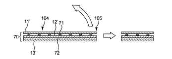
- the laminated portion 70 has the above-mentioned configuration, in the natural state of the exterior body 10 (that is, the relaxed state in which the stretched state of the first sheet 11 is released), the laminated portion 70 is as shown in FIG.
- the leg opening is curved toward the non-skin facing surface side with the open end LS as the free end.
- the reason why the laminated portion 70 warps toward the non-skin facing surface side is that the ease of contraction when the stretched state of the first sheet 11 is released and the laminated portion 70 contracts is the first sheet 11 side and the third. This is because it differs from the seat 13 side.
- the laminated portion 70 tends to shrink on the first sheet 11 side, while the laminated portion 70 tends to shrink.
- the 13th side of the 3rd sheet is hard to shrink.
- the laminated portion 70 tends to warp toward the first sheet 11 side so that the bimetal material warps due to the difference in expansion coefficient.
- the contraction force of the elastic member 8 is applied, and the laminated portion 70 is warped more greatly.
- the opening edge LA along the leg opening LH is such that the laminated portion 70 is folded back. Due to the heavy structure, the fit between the leg opening and the wearer's body is improved. Moreover, since the portion where the laminated portion 70 is warped comes into contact with the wearer's body with a certain width, the tightening force caused by the contraction of the leg opening is dispersed and acts like an air cushion for tightening. Traces are less likely to occur on the wearer's skin. This effectively suppresses the occurrence of skin troubles.
- the open end LS of the leg opening moves away from the wearer's skin, so that the open end LS comes into contact with the wearer's skin, resulting in a sense of discomfort. Is unlikely to occur.
- the first sheet 11 is joined to the second sheet 12 in the extended state.
- the third sheet 13 is joined to the second sheet 12 in a state where the first sheet 11 is extended.
- the facing regions of the first sheet 11 and the second sheet 12 are partially joined by a plurality of joining portions 71.
- the second sheet 12 and the third sheet 13 are bonded to each other by an adhesive 72 such as a hot melt adhesive on substantially the entire surface of the facing regions of the two.
- An elastic member (not shown) for forming leg gathers is arranged between the second sheet 12 and the third sheet 13 in an extended state.
- “Almost the entire surface is joined” means that the area of the facing region between the second sheet 12 and the third sheet 13 is preferably 50% or more, more preferably 90% or more, still more preferably 95% or more, still more preferably 98. % Or more are joined. By doing so, when the first sheet 11 side contracts, the third sheet 13 side becomes easier to follow and warps more.
- the warp width W (see FIG. 5) of the laminated portion 70 is preferably 1 mm or more, more preferably 3 mm or more, and more preferably 20 mm or less. It is preferably 15 mm or less, and more preferably 15 mm or less.
- the warp width W is preferably 1 mm or more and 20 mm or less, and more preferably 3 mm or more and 15 mm or less.
- the warp width W of the laminated portion 70 is measured by the following method. In the natural state (contracted state of the elastic member) of the measurement target in the diaper 1, the point where the warp width is maximized from the upper part of the warp portion is measured with a ruler.
- first sheet 11 and the second sheet 12 are intermittently partially joined in the vertical direction X and the horizontal direction Y of the diaper 1 in the laminated portion 70.
- 6 (a) and 6 (b) schematically show a state in which the first sheet 11 and the second sheet 12 are joined in a scattered manner by a plurality of joining portions 71.
- the joint portions 71 are arranged in multiple rows along the vertical direction X of the diaper 1, and the joint portions 71 are arranged in multiple rows along the horizontal direction Y. .. That is, the joint portion 71 is arranged at the intersection of the grids extending along the vertical direction X and the horizontal direction Y, respectively.
- the joint portions 71 are arranged in a houndstooth pattern.
- the pitch Xp of the joint portions 71 adjacent to each other along the vertical direction X and the pitch Yp of the joint portions 71 adjacent to each other along the horizontal direction Y are independently 1 mm or more, particularly 3 mm. It is preferably 15 mm or less, and particularly preferably 30 mm or less.
- the pitch P between the closest joint portions 71 is preferably 1.5 mm or more, particularly 4.5 mm or more, and 20 mm or less, particularly 40 mm or less. preferable.
- the total area of the joined portions 71 is preferably 0.3% or more with respect to the area of the laminated portion 70, and is 0. It is more preferably 5.5% or more, more preferably 10% or less, still more preferably 20% or less.
- the laminated portion 70 is successfully warped.
- FIGS. 6A and 6B show a circular joint portion 71, but the shape of the joint portion 71 is not limited to this, and a shape other than a circular shape, for example, a polygonal shape such as a triangle or a quadrangle, is shown. , Oval or star, or a combination thereof.
- the angle ⁇ formed by the tangent TL of the opening end LS at the laminated portion 70 and the lateral direction Y of the diaper 1 is 1 degree or more. It is preferably 10 degrees or higher, more preferably 20 degrees or higher, and even more preferably 20 degrees or higher.
- the angle ⁇ is preferably less than 90 degrees, more preferably 80 degrees or less, and even more preferably 70 degrees or less.
- the angle ⁇ is preferably 1 degree or more and 90 degrees or less, more preferably 10 degrees or more and 80 degrees or less, and further preferably 20 degrees or more and 70 degrees or less.
- the laminated portion 70 will be successfully warped with the open end LS as the free end, and the laminated portion 70 will be successfully warped. If all the positions of the open end LS located at are filled, the laminated portion 70 will be more successfully warped with the open end LS as the free end.
- FIG. 7 a suitable manufacturing method for the diaper 1 of the above-described embodiment will be described with reference to FIG. 7.
- two rows of strip-shaped first raw fabrics 11'and 11' are continuously fed out in parallel and separated by a predetermined distance from the original fabric roll (not shown) and conveyed in one direction. do.
- the strip-shaped second original fabric 12'and third original fabric 13' are continuously fed out from the original fabric roll (not shown) and conveyed in the same direction as the first original fabric 11'. ..
- the first raw fabric 11' is the material of the first sheet 11 in the diaper 1. Further, the second raw fabric 12'and the third raw fabric 13'are the materials of the second sheet 12 and the third sheet 13 in the diaper 1, respectively. Therefore, the first original fabric 11'has elasticity. On the other hand, both the second original fabric 12'and the third original fabric 13'are non-stretchable. The first raw fabric 11'has elasticity along its transport direction.
- the width of the second original fabric 12' is the widest, and the width of the first original fabric 11'and the third original fabric 13'
- the width of' is narrower than the width of the second original fabric 12'.
- the magnitude relationship is not particularly limited between the width of the first original fabric 11'and the width of the third original fabric 13'.
- the first raw fabric 11'and the second original fabric 12'in two rows are joined at the joint portion 100.
- the first raw fabric 11' is conveyed along one direction in an extended state, and is joined to the second original fabric 12'that is conveyed along the same direction.
- Each first original fabric 11' is arranged at each side edge portion in the second original fabric 12'.
- Each first raw fabric 11' is located inside the side edge of the second original fabric 12'.
- the bonding portion 100 includes an ultrasonic bonding device 101 and an anvil roll 102 arranged at a position facing the ultrasonic bonding device 101.
- the joining of the two original fabrics 11'and 12'by the joining portion 100 is preferably a partial joining.
- a preferred embodiment of the partial joining is a mode in which the first raw fabric 11'and the second original fabric 12'are intermittently partially joined in the transport direction thereof and the direction orthogonal to the transport direction thereof.
- a plurality of joints are formed by this partial joint.
- the arrangement pattern of the joint portion is, for example, as shown in FIGS. 6 (a) and 6 (b) described above.
- the Y direction shown in these figures coincides with the transport direction of the first original fabric 11'and the second original fabric 12'.
- the first raw fabric 11' has elasticity along its transport direction
- the first raw fabric 11' can be manufactured by a known method. For example, (1) a step of joining a plurality of elastic filaments to a sheet material so as to extend in one direction in a non-stretched state to obtain a composite material, and (2) a circumference of a ridge portion and a groove portion extending along the axial direction, respectively.
- the first raw fabric by a step of supplying the composite material between a pair of tooth groove rolls alternately held along the direction and meshing with each other to stretch the composite material and impart elasticity to the composite material. 11'can be manufactured.
- the first raw fabric 11'manufactured in this way may be joined to the second raw fabric 12'.
- the laminated body 103 of the first raw fabric 11'and the second original fabric 12' is formed.
- the side edge of the laminated body 103 is a side edge located on the outer side in the width direction of the second original fabric 12'.
- the third original fabric 13' is joined to the laminated body 103.
- the laminated sheet 104 of the exterior body having the laminated portion in which the three raw fabrics of the first raw fabric 11', the second raw fabric 12'and the third raw fabric 13' are laminated is manufactured.
- each side edge thereof coincides with each side edge of the second original fabric 12'.
- the manufacturing process of the laminated sheet 104 of the exterior body is also referred to as a “laminated sheet manufacturing process”.
- the bonding between the second original fabric 12'and the third original fabric 13' is, for example, substantially the entire surface of the two surfaces of the third original fabric 13', which face the second original fabric 12'. It is achieved by applying a hot melt adhesive (not shown) to the surface and bonding the two original fabrics 12'and 13'with the adhesive.
- a hot melt adhesive (not shown) to the surface and bonding the two original fabrics 12'and 13'with the adhesive. The meaning of "almost the entire surface" is as described above.
- FIG. 8 shows an example of a joining region when the second raw fabric 12'and the third original fabric 13' are bonded with an adhesive.
- An adhesive is applied to the region shown by hatching in the figure, and both original fabrics 12'and 13' are joined.
- reference numeral 8 is an elastic member for forming leg gathers.
- reference numeral 105 indicates the position of the planned cutting portion to be cut in the laminated sheet cutting step described later.
- the facing surfaces of the two raw fabrics 12'and 13' are joined to each other at least substantially the entire surface.
- an elastic member 8 for forming leg gathers is arranged between the two original fabrics 12'and 13'in an extended state.
- the position of the elastic member 8 is set along the position along the planned formation position of the leg opening LH in the laminated sheet 104 of the exterior body.
- the elastic member 8 is in an extended state between the second original fabric 12'and the third original fabric 13'while regularly swinging in the direction orthogonal to the transport direction. Place with.
- a device for swinging the elastic member 8 in a direction orthogonal to the transport direction thereof a device known in the art can be used without particular limitation.
- the laminated sheet 104 of the exterior body is manufactured by joining the first raw fabric 11', the second original fabric 12', and the third raw fabric 13'. Apart from this production, as shown in FIG. 7, the absorbent main body 2 is manufactured in advance, and an adhesive such as a hot melt adhesive is applied to the absorbent main body 2 (not shown). Further, the absorbent main body 2 is rotated 90 degrees with respect to the transport direction to join the laminated sheet 104 of the exterior body. This process is also referred to as an "absorbent main body placement process". When the absorbent main body 2 and the laminated sheet 104 are merged, the laminated sheet 104 is turned upside down so that the absorbent main body 2 is arranged on the surface side of the laminated sheet 104 where the third original fabric 13'is located. .. The absorbent main body 2 is intermittently arranged on the laminated sheet 104 along the transport direction of the laminated sheet 104.
- the bonding between the absorbent main body 2 and the laminated sheet 104 of the outer body in the absorbent main body arranging step can be performed by, for example, an adhesive as described above.
- an adhesive may be applied to the entire surface of the facing surface between the absorbent main body 2 and the laminated sheet 104, or an adhesive may be partially applied to the facing surface to partially apply the adhesive to the absorbent main body 2 and the laminated sheet 104. May be joined.
- the laminated sheet 104 of the exterior body is cut at the planned cutting portion 105 in a shape corresponding to the shape of the leg opening LH. do.
- This process is also referred to as a "laminated sheet cutting process".
- a leg opening LH is formed along the elastic member 8 at a position in the vicinity of the elastic member 8 in the laminated sheet 104 of the exterior body in which the absorbent main body 2 is arranged.
- This laminated sheet cutting step can be carried out by using the same method as the conventional method for manufacturing this kind of article such as a rotary cutter and a laser cutter.
- the laminated sheet 104 of the exterior body is cut so that at least the laminated portions 70 of the three raw fabrics 11', 12', 13'are present in the planned cutting portion 105. do.
- the first raw fabric 11'constituting the laminated sheet 104 is in an elongated state.
- the stretched state of the first raw fabric 11' is released by cutting as shown in FIG. 9, and the scheduled cutting portion 105 is freed.
- the laminated portion 70 in the laminated sheet 104 shrinks so as to warp.
- the laminated portion 70 at the opening edge of the leg opening has a curved shape (see FIG. 5).
- the warping of the laminated portion 70 occurs toward the non-skin facing surface side.
- the warp of the laminated portion 70 in the laminated portion 70 existing in the planned cutting portion 105, not only the first original fabric 11'is laminated with the second original fabric 12', but also the third original fabric 13'is the second. It becomes even more prominent when it is joined to the original fabric 12'.
- the third raw fabric 13'and the second raw fabric 12' are bonded with, for example, a hot melt adhesive 72. It is preferable to have.
- the angle ⁇ formed by the tangent TL of the planned cutting portion 105 and the transport direction MD of the laminated sheet 104 is preferably set to 1 degree or more, more preferably 10 degrees or more, and 20 degrees or more. It is more preferable to set to. Further, the angle ⁇ is preferably set to less than 90 degrees, more preferably 80 degrees or less, and even more preferably 70 degrees or less. The angle ⁇ is preferably set to 1 degree or more and less than 90 degrees, more preferably 10 degrees or more and 80 degrees or less, and even more preferably 20 degrees or more and 70 degrees or less.
- the laminated portion 70 will be successfully warped with the open end LS as the free end, and the laminated portion will be successfully warped. If all the positions of the planned cutting portion 105 located at 70 are filled, the laminated portion 70 will be more successfully warped with the open end LS as the free end.
- the laminated sheet 104 of the exterior body is folded in the width direction (direction orthogonal to the transport direction of the laminated sheet 104). Specifically, as shown in FIG. 7, both side portions 104a and 104a of the laminated sheet 104 of the exterior body along the transport direction are folded back so as to cover both ends in the longitudinal direction of the absorbent main body 2 to cover the longitudinal length of the absorbent main body 2. After fixing both ends in the direction, the laminated sheet 104 is folded in half in the width direction together with the absorbent body 2. In this way, the diaper continuum 1'is obtained.
- an elastic member (not shown) for forming waist gathers can be supplied in an extended state.
- the diaper continuous body 1' has a laminated sheet 104 of an exterior body in which the front body side and the back body side are overlapped, and an absorbent main body 2 intermittently fixed to the laminated sheet 104.
- the diaper continuous body 1'and the laminated sheet 104 of the exterior body have a planned formation portion of the side seal portion S, that is, a planned split portion 106 between the absorbent main bodies 2 and 2 in the transport direction.
- the front body side and the back body side of the laminated sheet 104 of the exterior body are in a state of directly overlapping each other without sandwiching the absorbent main body 2.
- a pair of side seal portions S, S are formed on the planned division portion 106 in the diaper continuum 1'manufactured in this manner, and after the side seal portions S, S are formed or the side seal portions S, S are formed.
- a pants-type absorbent article cutting step is performed in which the diaper continuous body 1'(specifically, the laminated sheet 104 of the exterior body) is divided along the width direction at the planned division portion 106.
- the desired individual diaper 1 is manufactured.
- this step releases the stretched state of the diaper continuum 1', and the opening edge portion of the leg opening of the diaper 1 is greatly warped toward the non-skin facing surface side.
- the apparatus and method described in Japanese Patent Application Laid-Open No. 2013-256109 can be used for the formation of the side seal portion S and the division of the diaper continuum 1'in the planned division portion 106.
- the laminated portion in the opening edge LA along the leg opening is 70, and the opening end LS of the leg opening is set as a free end on the non-skin facing surface side. It has a curved shape. According to the diaper 1 having such a shape, the fit between the leg opening and the wearer's body is improved. Moreover, the traces of tightening due to the leg openings are less likely to occur on the wearer's skin. Moreover, since the open end LS of the leg opening moves away from the wearer's skin, the discomfort caused by the open end LS coming into contact with the wearer's skin is less likely to occur.
- the obtained diaper 1 can be attached to an additional process. For example, as shown in FIG. 11, while transporting individually divided diapers 1, the diaper 1 is rotated 90 degrees with respect to the transport direction D, and is subjected to a rotation step of matching the vertical direction X of the diaper 1 with the transport direction D. Can be done.
- the diaper 1 transported in a state where the vertical direction X and the transport direction D coincide with each other by the rotation process is then subjected to the flap portions 15, which are located outside the absorbent main body 2 in the diaper 1 in the horizontal direction Y, respectively. 15 is subjected to a step of folding onto the absorbent body 2. This step is performed for the purpose of accommodating the diaper 1 in the packaging bag. As shown in FIG. 11, the flap portions 15 and 15 may be folded toward the same side of the diaper 1 or toward different sides (not shown). As described above, in the diaper 1, since the opening edge of the leg opening is in a state of being warped toward the non-skin facing surface side, the flaps 15 and 15 are warped when folded. The open edge portion tends to be the starting point of bending of the flap portions 15 and 15, which stabilizes the folded state of the flap portions 15 and 15.
- the diaper 1 with the flap portions 15 and 15 folded is conveyed while maintaining that state. Then, the diaper 1 in the transported state is subjected to a step of folding in half along a virtual folding line L extending in a direction orthogonal to the transport direction. The diaper 1 folded in this way is packed in a bag in the next step.
- FIGS. 12 to 14 Regarding the embodiments shown in FIGS. 12 to 14, only the points different from the embodiments shown in FIGS. 7 to 11 will be described, and the description of the embodiments shown in FIGS. 7 to 11 will be appropriately described for the points not particularly described. Applies. Further, in FIGS. 12 to 14, the same members as those in the embodiments shown in FIGS. 7 to 11 are designated by the same reference numerals.
- FIG. 12 shows another example of the joining region when the second raw fabric 12'and the third original fabric 13' are bonded with an adhesive.
- An adhesive is applied to the region shown by hatching in the figure, and both original fabrics 12'and 13' are joined.
- the third original fabric 13' is coated with an adhesive over the entire area, and the facing surface with the second original fabric 12'is bonded over the entire surface.
- the third original fabric 13' is coated with an adhesive over the entire area, and the surface facing the second original fabric 12'is entirely covered. It is joined.
- the elastic member 8 for forming the leg gather does not swing in the width direction of the laminated sheet 104 of the exterior body, and the conveying direction of the laminated sheet 104 It is arranged linearly along the MD.
- the arrangement position of the elastic member 8 is a region where the second original fabric 12'and the third original fabric 13' are bonded with an adhesive.
- the elastic member 8 for forming the leg gather is not used.
- the first raw fabric 11' which is a stretchable original fabric, was conveyed in parallel in two rows in the conventional embodiment, but in the present embodiment, the wide first original fabric 11'is conveyed in a single row. I am transporting it.
- the three raw fabrics of the first raw fabric 11', the second raw fabric 12'and the third raw fabric 13' are elastically laminated on the laminated portion 70. Although the member 8 is not arranged, the warp of the laminated portion 70 is sufficiently exhibited.
- the present invention has been described above based on the preferred embodiment, the present invention is not limited to the above embodiment.
- the laminated portion composed of the first sheet 11, the second sheet 12, and the third sheet 13 is provided on the front body F, but instead of or in addition to this, the laminated portion is provided.
- the portion may be provided on the back body R.
- the elastic member 8 may be arranged between the second sheet 12 and the third sheet 13 at the laminated portion.
- the laminated portion is formed by laminating the first sheet 11, the second sheet 12, and the third sheet 13 in this order on the exterior body 10, but instead of this, the second sheet is formed.
- the sheet 12, the first sheet 11, and the third sheet 13 may be laminated in this order to form a laminated portion.
- the second sheet 12 can form the outermost surface of the exterior body 10.
- the elastic member 8 can be arranged between the third sheet 13 and the first sheet 11 in an extended state along the leg opening LH.
- the third original fabric 13' was joined to the second original fabric 12', but instead, the third original fabric 13'was joined to the first original fabric 11'. It may be joined.
- the elastic member 8 is arranged in an extended state while swinging between the first raw fabric 11'and the third original fabric 13' along the position where the leg opening LH is to be formed.
- the laminated portion 70 existing in the planned cutting portion 105 of the laminated sheet 104 of the exterior body not only the third original fabric 13'is laminated with the first original fabric 11', but also the second original fabric 13'is laminated. It is preferable that the original fabric 12'is joined to the first original fabric 11'.
- the present invention further discloses the following pants-type absorbent article and a method for producing the same.
- It has a vertical direction extending from the ventral side of the wearer to the dorsal side through the crotch part and a lateral direction orthogonal to the vertical direction, and the crotch part arranged in the crotch part and the wearer's inseam rather than the crotch part.
- An absorbent body containing an absorbent core that is divided into a ventral portion arranged on the ventral side and a dorsal portion arranged on the dorsal side of the wearer rather than the inseam, and an absorbent core that absorbs and retains body fluid, and the absorption thereof.
- a pair of side seals are provided with an exterior body arranged on the non-skin facing surface side of the sex body, and both side portions of the exterior body along the vertical direction on each of the ventral side portion and the dorsal side portion are joined to each other.
- a pants-type absorbent article in which a portion, a waist opening and a pair of leg openings are formed.
- the exterior body having an open edge portion along the leg opening has a laminated portion including a first elastic sheet, a non-stretchable second sheet, and a non-stretchable third sheet, at least in part thereof. Consists of The first sheet is joined to the second sheet in the stretched state, and the third sheet is joined to the first sheet or the second sheet in the stretched state of the first sheet.
- a pants-type absorbent article in which the laminated portion of the opening edge portion is curved toward the non-skin facing surface side with the opening end of the leg opening as a free end.
- ⁇ 2> The second sheet and the third sheet are joined, and an elastic member is arranged in an extended state along the leg opening between the two sheets, or the first sheet and the third sheet are joined.
- the pants-type absorbent article according to ⁇ 1> wherein an elastic member is arranged between the two sheets in an extended state along the leg opening.
- the second sheet and the third sheet are joined,
- the pants-type absorbent article according to ⁇ 1> or ⁇ 2>, wherein the second sheet and the third sheet are joined to substantially the entire surface of the facing regions of both sheets.
- ⁇ 4> The pants type according to any one of ⁇ 1> to ⁇ 3>, wherein the first sheet and the second sheet are intermittently partially joined in the vertical direction and the horizontal direction of the pants type absorbent article.
- the angle ⁇ formed by the tangent line of the opening end of the opening edge of the leg opening and the lateral direction of the pants-type absorbent article is 1 degree or more and less than 90 degrees, said ⁇ 1> to The pants-type absorbent article according to any one of ⁇ 4>.
- An elastic member for forming waist gathers is fixed to the exterior body,
- the first sheet includes a ventral first sheet constituting the ventral portion and a dorsal first sheet constituting the dorsal portion.
- the ventral first sheet, the dorsal first sheet, and the second sheet have an extension portion extending outward from the vertical end portion of the elastic member.
- the first sheet has elasticity in the lateral direction and has elasticity.
- the first sheet includes two fiber sheets and an elastic member interposed between the two sheets.
- the pants type according to any one of ⁇ 1> to ⁇ 11>, wherein both of the two fiber sheets are expandable and can be extended in the same direction as the elastic member extends.
- the elastic member is an elastic filament formed by stretching an elastic resin in a molten or softened state, is continuously arranged over the entire length in the lateral direction of the first sheet, and extends in one direction without intersecting with each other.
- the pants-type absorbent article according to ⁇ 12> which is arranged in such a manner.
- the second sheet and the third sheet are bonded with preferably 50% or more, more preferably 90% or more, still more preferably 95% or more, still more preferably 98% or more of the area of the facing region thereof.
- the pants-type absorbent article according to any one of ⁇ 1> to ⁇ 13>. ⁇ 15> It has a vertical direction extending from the ventral side of the wearer to the dorsal side through the crotch part and a lateral direction orthogonal to the vertical direction, and the crotch part arranged in the crotch part and the wearer's inseam rather than the crotch part.
- An absorbent body containing an absorbent core that is divided into a ventral portion arranged on the ventral side and a dorsal portion arranged on the dorsal side of the wearer rather than the inseam, and an absorbent core that absorbs and retains body fluid, and the absorption thereof.
- a pair of side seals are provided with an exterior body arranged on the non-skin facing surface side of the sex body, and both side portions of the exterior body along the vertical direction on each of the ventral side portion and the dorsal side portion are joined to each other.
- a method of manufacturing a pants-type absorbent article in which a portion, a waist opening and a pair of leg openings are formed.
- It has a laminated sheet cutting step of cutting a laminated sheet of the exterior body in a region between the absorbent main bodies adjacent to each other along a transport direction in a shape corresponding to the shape of the leg opening at a planned cutting portion.
- a method for manufacturing a pants-type absorbent article which cuts a laminated sheet of an exterior body so that at least the laminated portion is present in the planned cutting portion in the laminated sheet cutting step.
- an elastic member is provided between the second and third raw fabrics or between the first and third raw fabrics along the planned formation position of the leg opening.
- the manufacturing method according to ⁇ 15> which is arranged in an extended state.
- the laminated sheet is such that at least the laminated portion in which the third original fabric is joined to the first original fabric or the second original fabric is present in the planned cutting portion of the laminated sheet of the exterior body.
- the shape of the planned cutting portion is determined by the tangent line of the planned cutting portion and the laminated sheet.
- ⁇ 19> The manufacturing method according to any one of ⁇ 15> to ⁇ 18>, wherein the third raw fabric is joined to the second raw fabric in the laminated sheet manufacturing step.
- ⁇ 20> In the laminated sheet manufacturing process, a hot melt adhesive is applied to substantially the entire surface of the two surfaces of the third raw fabric facing the second original fabric, and the adhesive is used to form the second original fabric and the third original fabric.
- the manufacturing method according to ⁇ 19> above. ⁇ 21> In any one of the above ⁇ 15> to ⁇ 20>, in the laminated sheet manufacturing process, the first raw fabric and the second raw fabric are intermittently partially joined in the transport direction thereof and the direction orthogonal to the transport direction thereof. The manufacturing method described.
- ⁇ 22> After the laminated sheet cutting step, a step of folding the laminated sheet of the exterior body in half in a direction orthogonal to the transport direction, and a step of folding the laminated sheet in half.
- a side seal portion is formed in the planned division portion of the laminated sheet of the exterior body folded in half, and the laminated sheet of the exterior body is formed in the planned division portion after the formation of the side seal portion or at the same time as the formation of the side seal portion.
- the manufacturing method according to ⁇ 22> which comprises a step of folding the pants-type absorbent article in a folded state with the flap portion in half along a virtual fold line extending in a direction orthogonal to the transport direction.
- a composite material is obtained by joining a plurality of elastic filaments to a sheet material so as to extend in one direction in a non-stretched state.
- the composite material is supplied and stretched between a pair of tooth groove rolls having ridges and grooves extending in the axial direction alternately along the circumferential direction and meshing with each other to stretch the composite material.
- the first raw fabric is manufactured, The manufacturing method according to any one of ⁇ 15> to ⁇ 23>, wherein the manufactured first raw fabric is joined to the second raw fabric.
- a pants-type absorbent article having a leg opening having a curved shape as compared with the conventional case, and a method for manufacturing the same.
Landscapes
- Health & Medical Sciences (AREA)
- Epidemiology (AREA)
- Engineering & Computer Science (AREA)
- Biomedical Technology (AREA)
- Heart & Thoracic Surgery (AREA)
- Vascular Medicine (AREA)
- Life Sciences & Earth Sciences (AREA)
- Animal Behavior & Ethology (AREA)
- General Health & Medical Sciences (AREA)
- Public Health (AREA)
- Veterinary Medicine (AREA)
- Absorbent Articles And Supports Therefor (AREA)
Abstract
パンツ型吸収性物品(1)におけるレッグ開口部(LH)に沿う開口縁部(LA)は、少なくともその一部が、伸縮性を有する第1シート(11)、非伸縮性の第2シート(12)、及び非伸縮性の第3シート(13)からなる積層部位(70)を有する外装体(10)からなる。第1シート(11)は伸長状態で第2シート(12)と接合されているとともに、第3シート(13)は第1シート(11)の伸長状態において第1シート(11)又は第2シート(12)と接合されている。開口縁部(LA)における積層部位(70)が、レッグ開口部(LH)の開口端(LS)を自由端として非肌対向面側に向けて反り返った形状をしている。
Description
本発明はパンツ型吸収性物品及びその製造方法に関する。
パンツ型吸収性物品は、一般に吸収性コアを有する吸収性本体と、該吸収性本体に接合された外装体とを備えており、ウエスト開口部及び一対のレッグ開口部を備えているパンツ型の形態を有している。パンツ型吸収性物品における外装体は、該外装体に伸縮性を付与する目的で弾性部材を備えており、該弾性部材を保持固定するために複数枚のシートの積層体から構成されている。例えば特許文献1には、外装体を三枚のシートから構成したパンツ型吸収性物品が記載されている。この吸収性物品の外装体は、第1シート部材と第2シート部材を、複数の溶着部によって間欠的に溶着する工程と、第1シート部材とは反対側の第2シート部材の面と、第3シート部材との間に弾性部材を配置し、第2シート部材と第3シート部材とを接着剤で接合する工程とによって製造される。この製造方法によって、外装体には、該外装体の厚さ方向の肌側から非肌側に向かって、第1シート部材、第2シート部材及び第3シート部材が順に積層された積層部が形成される。このような構成を有するパンツ型吸収性物品によれば、柔らかく且つ弾性部材を破断させることなく外装体の補強が可能であると、同文献には記載されている。
本発明は、着用者の腹側から股間部を介して背側に延びる縦方向と該縦方向に直交する横方向とを有し、該股間部に配される股下部と、該股下部よりも着用者の腹側に配される腹側部と、該股下部よりも着用者の背側に配される背側部とに区分され、体液を吸収保持する吸収性コアを含む吸収性本体と、該吸収性本体の非肌対向面側に配された外装体とを具備し、該腹側部及び該背側部それぞれにおける該外装体の該縦方向に沿う両側部どうしが接合されて一対のサイドシール部、ウエスト開口部及び一対のレッグ開口部が形成されている、パンツ型吸収性物品に関する。
前記レッグ開口部に沿う開口縁部は、少なくともその一部が、伸縮性を有する第1シート、非伸縮性の第2シート、及び非伸縮性の第3シートからなる積層部位を有する前記外装体からなることが好ましい。
第1シートは伸長状態で第2シートと接合されているとともに、第3シートは第1シートの伸長状態において第1シート又は第2シートと接合されていることが好ましい。
前記開口縁部における前記積層部位が、前記レッグ開口部の開口端を自由端として非肌対向面側に向けて反り返った形状をしていることが好ましい。
前記レッグ開口部に沿う開口縁部は、少なくともその一部が、伸縮性を有する第1シート、非伸縮性の第2シート、及び非伸縮性の第3シートからなる積層部位を有する前記外装体からなることが好ましい。
第1シートは伸長状態で第2シートと接合されているとともに、第3シートは第1シートの伸長状態において第1シート又は第2シートと接合されていることが好ましい。
前記開口縁部における前記積層部位が、前記レッグ開口部の開口端を自由端として非肌対向面側に向けて反り返った形状をしていることが好ましい。
また本発明は、着用者の腹側から股間部を介して背側に延びる縦方向と該縦方向に直交する横方向とを有し、該股間部に配される股下部と、該股下部よりも着用者の腹側に配される腹側部と、該股下部よりも着用者の背側に配される背側部とに区分され、体液を吸収保持する吸収性コアを含む吸収性本体と、該吸収性本体の非肌対向面側に配された外装体とを具備し、該腹側部及び該背側部それぞれにおける該外装体の該縦方向に沿う両側部どうしが接合されて一対のサイドシール部、ウエスト開口部及び一対のレッグ開口部が形成されている、パンツ型吸収性物品の製造方法に関する。
伸縮性を有する第1原反を伸長状態で一方向に沿って搬送しつつ、同方向に沿って搬送される非伸縮性の第2原反と接合し、次いで第1原反の伸長状態を維持したままで、同方向に沿って搬送される非伸縮性の第3原反を第1原反又は第2原反と接合して、これら三枚の原反が積層された積層部位を有する前記外装体の積層シートを製造する積層シート製造工程を有することが好ましい。
第1原反の伸長状態を維持したままで一方向に沿って搬送される前記外装体の原反における一面に前記吸収性本体を搬送方向に沿って間欠的に配置する吸収性本体配置工程を有することが好ましい。
搬送方向に沿って隣り合う前記吸収性本体間の領域において、前記外装体の積層シートを、切断予定部において前記レッグ開口部の形状に対応する形状で切断する積層シート切断工程を有することが好ましい。
前記積層シート切断工程において、前記切断予定部に前記積層部位が少なくとも存在するように前記外装体の積層シートを切断することが好ましい。
伸縮性を有する第1原反を伸長状態で一方向に沿って搬送しつつ、同方向に沿って搬送される非伸縮性の第2原反と接合し、次いで第1原反の伸長状態を維持したままで、同方向に沿って搬送される非伸縮性の第3原反を第1原反又は第2原反と接合して、これら三枚の原反が積層された積層部位を有する前記外装体の積層シートを製造する積層シート製造工程を有することが好ましい。
第1原反の伸長状態を維持したままで一方向に沿って搬送される前記外装体の原反における一面に前記吸収性本体を搬送方向に沿って間欠的に配置する吸収性本体配置工程を有することが好ましい。
搬送方向に沿って隣り合う前記吸収性本体間の領域において、前記外装体の積層シートを、切断予定部において前記レッグ開口部の形状に対応する形状で切断する積層シート切断工程を有することが好ましい。
前記積層シート切断工程において、前記切断予定部に前記積層部位が少なくとも存在するように前記外装体の積層シートを切断することが好ましい。
特許文献1に記載の方法によってパンツ型吸収性物品を製造した場合、外装体それ自身を柔らかくすることは可能かも知れないが、パンツ型吸収性物品におけるレッグ開口部における着用者の身体とのフィット性に関しては改良の余地がある。この理由は、レッグ開口部における着用者の身体とのフィット性は、レッグ開口部に沿って配された糸状の弾性部材の収縮によって専ら達成されているところ、このような手段によるフィット性の向上には限界があるからである。
また、特許文献1に記載の方法によってパンツ型吸収性物品を製造した場合、外装体の端縁、例えばレッグ開口部の端縁が着用者の肌に接触することに起因する違和感の発生を防ぐことは容易でない。この理由は、パンツ型おむつの製造方法においては一般に、外装体の積層シートを切断することによってレッグ開口部を形成しており、切断された部位はそのままの状態となっており、当該部位について、着用者の肌と接した場合の違和感を低減するための特段の処理を施していないからである。
また、特許文献1に記載の方法によってパンツ型吸収性物品を製造した場合、外装体の端縁、例えばレッグ開口部の端縁が着用者の肌に接触することに起因する違和感の発生を防ぐことは容易でない。この理由は、パンツ型おむつの製造方法においては一般に、外装体の積層シートを切断することによってレッグ開口部を形成しており、切断された部位はそのままの状態となっており、当該部位について、着用者の肌と接した場合の違和感を低減するための特段の処理を施していないからである。
したがって本発明は、前述した従来技術が有する欠点を解消し得るパンツ型吸収性物品及びその製造方法に関する。
以下本発明を、その好ましい実施形態に基づき図面を参照しながら説明する。なお、以下の図面の記載において、同一又は類似の部分には、同一又は類似の符号を付している。図面は基本的に模式的なものであり、各寸法の比率などは現実のものとは異なる場合がある。
本発明のパンツ型吸収性物品は、着用者の前後方向、すなわち腹側から股間部を介して背側に延びる方向に対応する縦方向(図中符号「X」で示す方向)と、該縦方向に直交する横方向(図中符号「Y」で示す方向)とを有する。
以下の説明において、特に断らない限り、縦方向は、パンツ型吸収性物品の縦方向又はその構成部材(例えば吸収性本体)における縦方向に沿う方向であり、横方向は、パンツ型吸収性物品の横方向又はその構成部材における横方向に沿う方向である。
本発明のパンツ型吸収性物品は、着用者の股間部に配され、着用者の陰茎等の排泄部に対向する排泄部対向部(図示せず)を含む股下部(図中符号「B」で示す部分)と、該股下部よりも着用者の腹側(前側)に配される腹側部(図中符号「A」で示す部分)と、該股下部よりも着用者の背側(後側)に配される背側部(図中符号「C」で示す部分)との3つに区分される。
本発明のパンツ型吸収性物品は、体液を吸収保持する吸収性コア(図示せず)を含む吸収性本体(図中符号「2」で示す部材)と、該吸収性本体の非肌対向面側に配された外装体(図中符号「10」で示す部材)とを具備し、該腹側部及び該背側部それぞれにおける該外装体の該縦方向に沿う両側部(図中符号「10S」で示す部分)どうしが接合されて一対のサイドシール部(図中符号「S」で示す部分)、ウエスト開口部(図中符号「WH」で示す部分)及び一対のレッグ開口部(図中符号「LH」で示す部分)が形成されている。
図1~図3には、本発明のパンツ型吸収性物品の一実施形態であるパンツ型おむつ1が示されており、おむつ1は前記の構成を備えている。
以下の説明において、特に断らない限り、縦方向は、パンツ型吸収性物品の縦方向又はその構成部材(例えば吸収性本体)における縦方向に沿う方向であり、横方向は、パンツ型吸収性物品の横方向又はその構成部材における横方向に沿う方向である。
本発明のパンツ型吸収性物品は、着用者の股間部に配され、着用者の陰茎等の排泄部に対向する排泄部対向部(図示せず)を含む股下部(図中符号「B」で示す部分)と、該股下部よりも着用者の腹側(前側)に配される腹側部(図中符号「A」で示す部分)と、該股下部よりも着用者の背側(後側)に配される背側部(図中符号「C」で示す部分)との3つに区分される。
本発明のパンツ型吸収性物品は、体液を吸収保持する吸収性コア(図示せず)を含む吸収性本体(図中符号「2」で示す部材)と、該吸収性本体の非肌対向面側に配された外装体(図中符号「10」で示す部材)とを具備し、該腹側部及び該背側部それぞれにおける該外装体の該縦方向に沿う両側部(図中符号「10S」で示す部分)どうしが接合されて一対のサイドシール部(図中符号「S」で示す部分)、ウエスト開口部(図中符号「WH」で示す部分)及び一対のレッグ開口部(図中符号「LH」で示す部分)が形成されている。
図1~図3には、本発明のパンツ型吸収性物品の一実施形態であるパンツ型おむつ1が示されており、おむつ1は前記の構成を備えている。
本明細書において、「肌対向面」は、吸収性物品又はその構成部材(例えば吸収性本体)における、吸収性物品の着用時に着用者の肌側に向けられる面、すなわち着用者の肌から相対的に近い側であり、「非肌対向面」は、吸収性物品又はその構成部材における、吸収性物品の着用時に肌側とは反対側に向けられる面、すなわち着用者の肌から相対的に遠い側である。なお、ここでいう「着用時」は、通常の適正な着用位置、すなわち当該吸収性物品の正しい着用位置が維持された状態を意味する。
腹側部Aは、おむつ1の前身頃Fの一部であり、背側部Cは、おむつ1の後身頃Rの一部である。股下部Bは、縦中心線CLxを縦方向Xに跨いでおり、前身頃Fから後身頃Rに存在している。縦中心線CLxは、図2に示す如き展開且つ伸長状態のおむつ1を縦方向Xに二等分して横方向Yに延びる仮想直線である。ここでいう「展開且つ伸長状態」とは、おむつ1をサイドシール部Sで切り離して展開状態とし、その展開状態のおむつ1を各部の弾性部材を伸長させて設計寸法(弾性部材の影響を一切排除した状態で平面状に拡げたときの寸法と同じ)となるまで拡げた状態をいう。
腹側部A及び背側部Cは、典型的にはそれぞれ、縦方向Xにおいてサイドシール部Sと同位置にある部分であり、おむつ1の着用時に着用者の胴周りに配される胴周り部である。股下部Bは、典型的には、外装体10の縦方向Xに沿う両側部10Sの一部であり、レッグ開口部LH,LH形成用の凹欠部である開口端LS,LSが形成された領域を含む。
本発明において、腹側部A、股下部B及び背側部Cは、展開且つ伸長状態のおむつ1を縦方向Xに三等分した場合の各領域であり得る。
腹側部A及び背側部Cは、典型的にはそれぞれ、縦方向Xにおいてサイドシール部Sと同位置にある部分であり、おむつ1の着用時に着用者の胴周りに配される胴周り部である。股下部Bは、典型的には、外装体10の縦方向Xに沿う両側部10Sの一部であり、レッグ開口部LH,LH形成用の凹欠部である開口端LS,LSが形成された領域を含む。
本発明において、腹側部A、股下部B及び背側部Cは、展開且つ伸長状態のおむつ1を縦方向Xに三等分した場合の各領域であり得る。
本実施形態では、吸収性本体2は平面視矩形形状を有し、その長手方向をおむつ1の縦方向Xに一致させて、外装体10の横方向Yの中央部に配置され、腹側部Aから背側部Cに縦方向Xに延在している。吸収性本体2の平面視における輪郭は、吸収体5の輪郭、より具体的には、吸収体の外面を形成するコアラップシート(図示せず)の平面視における輪郭と略一致する。吸収性本体2と外装体10とは接着剤によって接合されている。
吸収性本体2は、着用者の肌から相対的に近い位置に配置された液透過性の表面シート3、着用者の肌から相対的に遠い位置に配置された液不透過性若しくは液難透過性又は撥水性(要するに防漏性)の裏面シート(図示せず)、及び両シート間に介在配置された吸収体5を含んで構成されている。
吸収体5は、体液を吸収保持可能な吸収性コア(図示せず)と、該吸収性コアの肌対向面及び非肌対向面を含む外面を被覆するコアラップシート(図示せず)とを含んで構成されている。
吸収性本体2を構成するこれらの部材どうしは、接着剤等の公知の接合手段により一体とされている。
吸収性本体2は、着用者の肌から相対的に近い位置に配置された液透過性の表面シート3、着用者の肌から相対的に遠い位置に配置された液不透過性若しくは液難透過性又は撥水性(要するに防漏性)の裏面シート(図示せず)、及び両シート間に介在配置された吸収体5を含んで構成されている。
吸収体5は、体液を吸収保持可能な吸収性コア(図示せず)と、該吸収性コアの肌対向面及び非肌対向面を含む外面を被覆するコアラップシート(図示せず)とを含んで構成されている。
吸収性本体2を構成するこれらの部材どうしは、接着剤等の公知の接合手段により一体とされている。
吸収性本体2を構成する前記の各部材としては、この種の吸収性物品において通常使用されているものを特に制限なく用いることができる。例えば、表面シート3としては各種の不織布や開孔フィルム等を用いることができ、裏面シートとしては樹脂フィルムや、樹脂フィルムと不織布等とのラミネート等を用いることができる。吸収性コアは、典型的には、吸水性材料を主体とし、該吸水性材料として、木材パルプ等の繊維材料及び吸水性ポリマーから選択される1種以上を含有する。コアラップシートは液透過性を有し、典型的には、紙、不織布等からなる。
本実施形態では、外装体10は、図2に示すとおり、前身頃Fの胴周り部である腹側部A、及び後身頃Rの胴周り部である背側部C、腹側部Aと背側部Cとに挟まれた股下部Bに跨って配されている。外装体10は、図2に示す如きおむつ1の展開且つ伸長状態において、腹側部A及び背側部Cを構成する縦方向Xの両端部域が、縦方向Xよりも横方向Yの長さが長い長方形形状を有し、且つ股下部Bを構成する縦方向Xの中央域では、外装体10の縦方向Xに沿う両側部10S,10Sの一部である一対の開口端LS,LSが、横方向Yの中央に向かって凸の円弧状に湾曲しており、外装体10全体として砂時計形状を有している。
本実施形態では、腹側部A及び背側部Cそれぞれの縦方向Xの端部、すなわちウエスト端部にウエストギャザーが形成されている。前記ウエストギャザーは、外装体10と、外装体10に固定された複数のウエストギャザー形成用弾性部材7とを含んで構成されている。複数の弾性部材7は、それぞれ横方向Yに延在し、縦方向Xに間欠配置されている。前記ウエストギャザーは、外装体10を構成する後述の第2シート12の延出部12Eを折り返して形成された第2シート12の二枚重ねの部分に、弾性部材7を横方向Yに伸長させた状態で配置し、固定した後、弾性部材7を伸長状態から解放することで作製されている。弾性部材7の収縮により、おむつ1の全周にわたって実質的に連続した環状の前記ウエストギャザーが形成される。
また本実施形態では、一対のレッグ開口部LH,LHそれぞれの開口端LSに沿って、レッグギャザーが形成されている。レッグギャザーは、外装体10と、外装体10に固定されたレッグギャザー形成用弾性部材8とを含んで構成されている。弾性部材8は、おむつ1の前身頃Fにのみ配置されている。詳細には、前身頃Fにおける腹側部Aと股下部Bとを跨ぐように配置されている。レッグギャザーは、外装体10を構成する後述の第2シート12と第3シート13との間に、弾性部材8を伸長状態で固定した後、弾性部材8を伸長状態から解放することで作製されている。弾性部材8の収縮により、レッグ開口部LHの開口縁部のうち、前身頃Fの領域に前記レッグギャザーが形成される。弾性部材8は1本でも複数本でもよい。
また本実施形態では、一対のレッグ開口部LH,LHそれぞれの開口端LSに沿って、レッグギャザーが形成されている。レッグギャザーは、外装体10と、外装体10に固定されたレッグギャザー形成用弾性部材8とを含んで構成されている。弾性部材8は、おむつ1の前身頃Fにのみ配置されている。詳細には、前身頃Fにおける腹側部Aと股下部Bとを跨ぐように配置されている。レッグギャザーは、外装体10を構成する後述の第2シート12と第3シート13との間に、弾性部材8を伸長状態で固定した後、弾性部材8を伸長状態から解放することで作製されている。弾性部材8の収縮により、レッグ開口部LHの開口縁部のうち、前身頃Fの領域に前記レッグギャザーが形成される。弾性部材8は1本でも複数本でもよい。
図2及び図3に示すとおり、吸収性本体2の縦方向Xに沿う両側部には、おむつ1の着用時に着用者の肌側に起立する一対の防漏カフ6,6が配置されている。各防漏カフ6は、該防漏カフ6の主体をなす防漏カフ形成用シート60と、縦方向Xに伸長状態で該シート60に固定された弾性部材61とを含む。弾性部材61は、防漏カフ形成用シート60の自由端部に配置されている。
前述の如く構成された防漏カフ6においては、おむつ1の着用時に、該防漏カフ6が、弾性部材61の収縮力によって着用者の肌側に向かって起立する。このようにおむつ1の着用時に防漏カフ6が起立することで、着用者が排泄した尿等の体液が表面シート3を伝って横方向Yの外方へ漏れ出す、いわゆる横漏れが効果的に防止される。
本実施形態では、防漏カフ6は、図2に示すとおり、吸収性本体2の縦方向Xの略全長にわたって、吸収性本体2の縦方向Xに沿う側部に沿って連続的に配されており、防漏カフ6(防漏カフ形成用シート60)の縦方向Xの長さは、吸収性本体2の縦方向Xの長さと概ね同等である。
防漏カフ形成用シート60としては、この種の吸収性物品において防漏カフの素材として用いられているものを特に制限なく用いることができ、液抵抗性又は撥水性で且つ通気性を有するものが好ましく、例えば、単層又は多層の撥水性不織布、樹脂フィルムと不織布等とのラミネート材等を用いることができる。
弾性部材61、更には、前述の弾性部材7,8をはじめとする、おむつ1における各種の弾性部材の素材としては、特に断らない限り、この種の吸収性物品に通常用いられる各種公知の弾性材料を特に制限なく用いることができ、例えば、スチレン-ブタジエン、ブタジエン、イソプレン、ネオプレン等の合成ゴム、天然ゴム、EVA、伸縮性ポリオレフィン、ポリウレタン等が挙げられる。弾性部材の形態としては、断面が矩形、正方形、円形、多角形状等の糸状(糸ゴム等)若しくは紐状(平ゴム等)のもの、又はマルチフィラメントタイプの糸状のもの等を好ましく用いることができる。
弾性部材61、更には、前述の弾性部材7,8をはじめとする、おむつ1における各種の弾性部材の素材としては、特に断らない限り、この種の吸収性物品に通常用いられる各種公知の弾性材料を特に制限なく用いることができ、例えば、スチレン-ブタジエン、ブタジエン、イソプレン、ネオプレン等の合成ゴム、天然ゴム、EVA、伸縮性ポリオレフィン、ポリウレタン等が挙げられる。弾性部材の形態としては、断面が矩形、正方形、円形、多角形状等の糸状(糸ゴム等)若しくは紐状(平ゴム等)のもの、又はマルチフィラメントタイプの糸状のもの等を好ましく用いることができる。
外装体10は、相対的に着用者の肌(あるいは吸収体5)から遠い側に配置された第1シート11と、相対的に着用者の肌(あるいは吸収体5)から近い側に配置された第2シート12とを含んで構成されている。両シート11,12どうしは、各種の接合手段を介して互いに接合され一体化されている。第1シート11は、おむつ1の腹側部A及び背側部Cにおいて、外装体10の最外面を構成している。股下部Bにおける、おむつ1の縦方向Xの中央(縦中心線CLx)から縦方向Xの両外方に所定距離離間した範囲には、第1シート11は配置されておらず、外装体10の構成部材としては第2シート12のみが配置されている。外装体において第2シート12のみが配置されている部分では、第2シート12がおむつ1の外面を形成し得る。
図3に示すとおり、第2シート12は、1枚の連続したシートであるのに対し、第1シート11は、個々独立に存在する複数枚のシートを含んで構成されており、具体的には、腹側部A(より具体的には、腹側部Aの一対のサイドシール部S,Sに挟まれた領域)を構成する腹側第1シート110と、背側部C(より具体的には、背側部Cの一対のサイドシール部S,Sに挟まれた領域)を構成する背側第1シート111とを含んで構成されている。腹側第1シート110及び背側第1シート111は、それぞれ、腹側部A又は背側部Cから股下部Bに延出している。
腹側第1シート110及び背側第1シート111、並びに第2シート12は、それぞれ、図2及び図3に示すとおり、弾性部材7の縦方向Xの端部から外方に延出する延出部11E、12Eを有している。延出部11E、12Eは、弾性部材7側に折り返され、吸収性本体2の縦方向Xの端部を被覆している。弾性部材7側に折り返された延出部11E、12Eは、該延出部11E、12Eに対向する他の部材(第2シート12、吸収性本体2、防漏カフ形成用シート60、弾性部材7)に接着剤によって接合されている。第2シート12の延出部12Eは、その長さ(X方向に沿う長さ)が、腹側第1シート110及び背側第1シート111それぞれの延出部11Eの長さ(X方向に沿う長さ)よりも長くなっている。
なお、以下の第1シート11の説明は、特に断らない限り、腹側第1シート110及び背側第1シート111の双方に適用される。
なお、以下の第1シート11の説明は、特に断らない限り、腹側第1シート110及び背側第1シート111の双方に適用される。
外装体10は、第1シート11及び第2シート12に加えて第3シート13を有する。第3シート13は、前身頃Fにおいて腹側部Aと股下部Bとを跨ぐように外装体10の横方向Yの全域に存在している。外装体10のうち、第3シートが配されている部位においては、第3シート13が外装体10の最内面を構成している。
外装体10を平面視したとき、第3シート13は、その全域が第2シート12と重なっている。また第3シート13はその全域が、第1シート11の全域と重なっているか若しくは第1シート11の一部と重なっているか、又は第3シートはその一部が、第1シート11の全域と重なっているか若しくは第1シート11の一部と重なっている。
第1シート11は、横方向Yに伸縮性を有している。本実施形態では、第1シート11は、横方向Yに伸縮性を有する伸縮性シートを含んでおり、腹側第1シート110及び背側第1シート111は、それぞれ、該伸縮性シートである。第1シート11は、横方向Yに伸縮性を有することを前提として、横方向Yに伸縮性を有する伸縮性シート以外のシート(例えば非伸縮性シート)を含んでいてもよい。
本発明において、「横方向に伸縮性を有する」とは、具体的には、当該シート(例えば第1シート11)の、横方向Yの最大伸度が好ましくは50%以上であることを指す。
ここでいう「最大伸度」とは、測定対象(例えば第1シート11)をそれ以上伸ばせない長さ(材料破壊する直前の長さ)まで伸長したときの伸長率であり、下記式(1)によって求められる。
最大伸度(%)={(伸長後の長さ-伸長前の長さ)/伸長前の長さ}×100 …(1)
最大伸度の測定は次の手順で行うことができる。吸収性物品における測定対象の自然状態(弾性部材の収縮状態)において、Y方向に50mmの間隔の目印を付け、この目印の間隔を測定して、「伸長前の長さ」とする。次いで、測定対象をその伸縮方向に該測定対象が材料破壊する直前まで伸長させ、斯かる伸長状態での前記目印の間隔を測定して、「伸長後の長さ」とする。そして、これらの測定値を前記式(1)に代入して最大伸度を算出する。なお、測定対象を吸収性物品から切り出したものを測定サンプルとして測定に供してもよい。
最大伸度(%)={(伸長後の長さ-伸長前の長さ)/伸長前の長さ}×100 …(1)
最大伸度の測定は次の手順で行うことができる。吸収性物品における測定対象の自然状態(弾性部材の収縮状態)において、Y方向に50mmの間隔の目印を付け、この目印の間隔を測定して、「伸長前の長さ」とする。次いで、測定対象をその伸縮方向に該測定対象が材料破壊する直前まで伸長させ、斯かる伸長状態での前記目印の間隔を測定して、「伸長後の長さ」とする。そして、これらの測定値を前記式(1)に代入して最大伸度を算出する。なお、測定対象を吸収性物品から切り出したものを測定サンプルとして測定に供してもよい。
第1シート11を構成する伸縮性シートとしては、例えば(1)弾性繊維層の両面又は片面に伸長可能な繊維層が一体化されている伸縮性不織布、(2)ネット状の弾性シートの両面又は片面に伸長可能な繊維層が一体化されている伸縮性不織布、(3)弾性フィルムからなる弾性シートの両面又は片面に伸長可能な繊維層が一体化されている伸縮性不織布、(4)互いに交差せずに一方向に延びるように配列した多数の弾性フィラメントが、伸長可能な繊維層に一体化されてなる伸縮性不織布等を好ましく用いることができる。
ここでいう「伸長可能な繊維層」には、弾性を有する材料と一体化する前から伸長可能である繊維層の他に、弾性を有する材料との一体化後に機械加工等により伸長可能とされた繊維層が含まれる。
弾性繊維層と伸長可能な繊維層との一体化の方法としては、例えば、これらを積層して水流交絡又はエアスルー等により繊維を交絡させる方法、ヒートエンボス、接着剤、超音波等によって接合させる方法が挙げられる。
ここでいう「伸長可能な繊維層」には、弾性を有する材料と一体化する前から伸長可能である繊維層の他に、弾性を有する材料との一体化後に機械加工等により伸長可能とされた繊維層が含まれる。
弾性繊維層と伸長可能な繊維層との一体化の方法としては、例えば、これらを積層して水流交絡又はエアスルー等により繊維を交絡させる方法、ヒートエンボス、接着剤、超音波等によって接合させる方法が挙げられる。
図4には、第1シート11(腹側第1シート110、背側第1シート111)の好ましい一例である第1シート11Aが示されている。第1シート11Aは、前記(4)の伸縮性不織布に相当するものである。第1シート11Aは、非弾性繊維を主体とする伸長可能な繊維層どうしの間に糸状の弾性フィラメントが挟まれ、一体化された構成を有している。すなわち第1シート11Aは、該繊維層としての2枚の繊維シート16,17と、両シート16,17間に介在配置された該弾性フィラメントとしての弾性部材18とを含んで構成されている。斯かる構成を有する伸縮性不織布は、例えば、特開2009-61743号公報に記載の方法に従って製造することができる。
第1シート11Aを構成する2枚のシート16,17は、いずれも伸長可能なものである。シート16,17は、弾性部材18の延びる方向(横方向Y)と同方向に伸長可能になっている。伸長可能とは、(イ)シート16,17の構成繊維自体が伸長する場合と、(ロ)構成繊維自体は伸長しなくても、機械加工等により交点において結合していた繊維どうしが離れたり、繊維どうしの結合等により複数本の繊維で形成された立体構造が構造的に変化したり、構成繊維がちぎれたりして、シート16,17全体として伸長する場合とを包含する。
弾性部材18は、弾性樹脂が溶融又は軟化した状態で延伸されて形成された弾性フィラメントである。複数の弾性部材18は、それぞれ、第1シート11A(外装体10)の横方向Yの全長に連続して配されている。複数の弾性部材18は、互いに交差せずに一方向(横方向Y)に延びるように配列している。弾性部材18は、実質的に非伸長状態で2枚のシート16,17に接合されている。弾性部材18と繊維シート16,17との接合は、両シート16,17の構成繊維(非弾性繊維)が弾性部材18中に埋没した状態で該弾性部材18に融着することによりなされたものであり、ホットメルト接着剤等の接着剤を用いてなされたものではない。したがって、繊維シート16,17(非弾性繊維を主体とする伸長可能な繊維層)とこれに接合されている弾性部材18との間には接着剤が存在しない。
第1シート11Aは、弾性部材18の延びる方向(横方向Y)と同方向に伸縮可能である。第1シート11Aの伸縮性は、弾性部材18の弾性に起因して発現する。第1シート11を弾性部材18の延びる方向と同方向に引き伸ばすと、弾性部材18及び繊維シート16,17が伸長する。そして第1シート11Aの引き伸ばしを解除すると、弾性部材18が収縮し、その収縮に連れて繊維シート16,17が引き伸ばし前の状態に復帰する。また、第1シート11Aにおいては、その製造時に繊維シート16と繊維シート17との繊維の結合を一部壊すことで、伸びしろが設けてられているため、第1シート11Aを、弾性部材18の延びる方向(横方向Y)と同方向に引き伸ばしたときには、該シート11Aが横方向Yに縮む、いわゆる幅縮みをほとんど起こさずに伸長する。
第1シート11Aを構成する2枚の繊維シート16,17は、それぞれ、短繊維の不織布であり得る。不織布としては、エアスルー不織布、ヒートロール不織布、スパンレース不織布、スパンボンド不織布、メルトブローン不織布等が挙げられる。両シート16,17は、互いに同種でもよく、異種でもよい。ここでいう、「同種のシート」とは、シートの製造プロセス、シートの構成繊維の種類、構成繊維の繊維径や長さ、シートの厚みや坪量等がすべて同じであるシートどうしを意味する。これらのうちの少なくとも1つが異なる場合には、「異種のシート」である。また、弾性部材18(弾性フィラメント)は、例えば熱可塑性エラストマーやゴム等を原料とするものである。特に熱可塑性エラストマーを原料として用いると、通常の熱可塑性樹脂と同様に押出機を用いた溶融紡糸が可能であり、またそのようにして得られた弾性フィラメントは熱融着させやすいので、第1シート11Aに好適である。
第1シート11の坪量(第1シート11が、前述の第1シート11Aの如き積層構造である場合は該積層構造の坪量)は特に制限されないが、好ましくは20g/m2以上、より好ましくは30g/m2以上、そして、好ましくは60g/m2以下、より好ましくは55g/m2以下である。
本実施形態では、第2シート12及び第3シート13はいずれも非伸縮性シートである。第2シート12及び第3シート13は、非伸縮性であることを前提として、非伸縮性シート以外のシートを含んで構成されていてもよい。第2シート12及び第3シート13は、典型的には、非伸縮性シートからなる。
非伸縮性である第2シート12及び第3シート13の横方向Yの最大伸度は、好ましくは50%未満であり、0%でもよい。
非伸縮性である第2シート12及び第3シート13の横方向Yの最大伸度は、好ましくは50%未満であり、0%でもよい。
第2シート12及び第3シート13としては、各種製法による不織布、樹脂フィルムなどを用いることができ、不織布としては例えば、スパンボンド不織布、エアスルー不織布、ニードルパンチ不織布等が挙げられる。第2シート12及び第3シート13は単層構造でもよく、2枚以上のシートが積層された積層構造でもよい。
第2シート12及び第3シート13の坪量(第2シート12及び第3シート13が積層構造である場合は該積層構造の坪量)は特に制限されないが、好ましくはそれぞれ独立に13g/m2以上、より好ましくは15g/m2以上、そして、好ましくは30g/m2以下、より好ましくは25g/m2以下である。
第2シート12及び第3シート13の坪量(第2シート12及び第3シート13が積層構造である場合は該積層構造の坪量)は特に制限されないが、好ましくはそれぞれ独立に13g/m2以上、より好ましくは15g/m2以上、そして、好ましくは30g/m2以下、より好ましくは25g/m2以下である。
図3に示すとおり、外装体10は、第2シート12のみから構成される部位(すなわち股下部B)と、第1シート11及び第2シート12のみから構成される部位(すなわち、腹側部A及び背側部Cにおけるウエスト開口部WH近傍の部位)と、第1シート11、第2シート12及び第3シート13から構成される部位(すなわち、前身頃Fにおける腹側部Aから股下部Bにかけての部位)とを有する。以下、第1シート11、第2シート12及び第3シート13の三枚のシートから構成される部位のことを「積層部位70」ともいう。
積層部位70は、前身頃Fにおいて腹側部Aから股下部Bにかけての部位であり、レッグ開口部LHに沿ってレッグギャザーを形成するための弾性部材8が配されている部位に相当する。換言すると、図5に示すとおりレッグ開口部LHに沿う開口縁部LAは、少なくともその一部(具体的には該開口縁部LAのうち前身頃F側に位置する領域の一部)が積層部位70を有する外装体10から構成されている。
積層部位70が上述の構成を有していることによって、外装体10の自然状態(すなわち、第1シート11の伸長状態を解除した弛緩状態)においては、図5に示すとおり、積層部位70が、レッグ開口部の開口端LSを自由端として非肌対向面側に向けて反り返った形状をしている。積層部位70が非肌対向面側に向けて反り返る理由は、第1シート11の伸長状態が解除されて積層部位70が収縮するときの収縮のしやすさが、第1シート11側と第3シート13側とで相違するからである。詳細には、第1シート11は伸縮性を有するのに対して第2シート12及び第3シート13は非伸縮性であることから、積層部位70は第1シート11側が収縮しやすく、その一方で第3シート13側は収縮しにくい。その結果、バイメタル材料が膨張率の相違に起因して反り返るように、積層部位70は第1シート11側に向けて反り返りやすくなる。しかも弾性部材8が配されることで、弾性部材8の収縮力が加わり、積層部位70はより大きく反り返るようになる。
積層部位70が非肌対向面側に向けて反り返った形状をしている本実施形態のおむつ1によれば、レッグ開口部LHに沿う開口縁部LAが、積層部位70を折り返したような二重構造となることから、レッグ開口部と着用者の身体とのフィット性が向上する。しかも、積層部位70が反り返った部位は、一定の幅をもって着用者の身体と当接するので、レッグ開口部の収縮に起因する締め付け力が分散されて、エアクッションのような役割をし、締め付けの跡が着用者の肌に生じづらくなる。これによって肌トラブルの発生が効果的に抑制される。その上、積層部位70が非肌対向面側に向けて反り返ることでレッグ開口部の開口端LSが着用者の肌から遠ざかるので、該開口端LSが着用者の肌と接することに起因する違和感が生じにくい。
積層部位70においては、図5に示すとおり、第1シート11はその伸長状態で第2シート12と接合されている。これとともに第3シート13は、第1シート11が伸長している状態で第2シート12と接合している。第1シート11と第2シート12とは、両者の対向領域どうしが複数の接合部71によって部分接合されている。一方、第2シート12と第3シート13とは、ホットメルト接着剤等の接着剤72によって、両者の対向領域の略全面が接合されている。そして、第2シート12と第3シート13との間に、レッグギャザーを形成するための弾性部材(図示せず)が伸長状態で配されている。「略全面が接合」とは、第2シート12と第3シート13との対向領域の面積の好ましくは50%以上、更に好ましくは90%以上、一層好ましくは95%以上、より一層好ましくは98%以上が接合されていることをいう。こうすることで、第1シート11側が収縮した時に、第3シート13側が追従しやすくなり、より反り返るようになる。
以上の効果を一層顕著なものとする観点から、積層部位70の反り返り幅W(図5参照)は1mm以上であることが好ましく、3mm以上であることが更に好ましく、また20mm以下であることが好ましく、15mm以下であることが更に好ましい。反り返り幅Wは1mm以上20mm以下であることが好ましく、3mm以上15mm以下であることが更に好ましい。
積層部位70の反り返り幅Wは次の方法で測定される。おむつ1における測定対象の自然状態(弾性部材の収縮状態)において、反り返し部の上部から反り返り幅が最大となる点を定規にて測定する。
同様の観点から、積層部位70においては、第1シート11と第2シート12とが、おむつ1の縦方向X及び横方向Yにおいて、間欠的に部分接合されていることが好ましい。図6(a)及び(b)には、第1シート11と第2シート12とが複数の接合部71によって散点状に接合されている状態が模式的に示されている。図6(a)に示す配置パターンでは、おむつ1の縦方向Xに沿って接合部71が多列に配置されているとともに、横方向Yに沿って接合部71が多列に配置されている。つまり、接合部71は、縦方向X及び横方向Yに沿ってそれぞれ延びる格子の交点に配置されている。一方、図6(b)に示す配置パターンでは、接合部71は千鳥格子状に配置されている。
図6(a)に示す配置パターンの場合、縦方向Xに沿って隣り合う接合部71のピッチXp及び横方向Yに沿って隣り合う接合部71のピッチYpはそれぞれ独立に1mm以上、特に3mm以上であることが好ましく、また15mm以下、特に30mm以下であることが好ましい。
図6(b)に示す配置パターンの場合、最も近接する接合部71どうしのピッチPは1.5mm以上、特に4.5mm以上であることが好ましく、また20mm以下、特に40mm以下であることが好ましい。
図6(b)に示す配置パターンの場合、最も近接する接合部71どうしのピッチPは1.5mm以上、特に4.5mm以上であることが好ましく、また20mm以下、特に40mm以下であることが好ましい。
積層部位70においては、第1シート11と第2シート12とを接合するために接合部71の面積の総和は、積層部位70の面積に対して0.3%以上とすることが好ましく、0.5%以上とすることが更に好ましく、また10%以下とすることが好ましく、20%以下とすることが更に好ましい。このような割合で接合部71を形成することによって、積層部位70が首尾よく反り返るようになる。
なお図6(a)及び(b)には円形の接合部71が示されているが、接合部71の形状はこれに限られず、円形以外の形状、例えば三角形や四角形などの多角形の形状、楕円形若しくは星形、又はそれらの組み合わせを採用してもよい。
なお図6(a)及び(b)には円形の接合部71が示されているが、接合部71の形状はこれに限られず、円形以外の形状、例えば三角形や四角形などの多角形の形状、楕円形若しくは星形、又はそれらの組み合わせを採用してもよい。
更に同様の観点から、レッグ開口部の開口縁部LAのうち、図2に示すとおり、積層部位70における開口端LSの接線TLと、おむつ1の横方向Yとがなす角度θが1度以上であることが好ましく、10度以上であることが更に好ましく、20度以上であることが一層好ましい。また角度θは90度未満であることが好ましく、80度以下であることが更に好ましく、70度以下であることが一層好ましい。角度θは1度以上90度以下であることが好ましく、10度以上80度以下であることが更に好ましく、20度以上70度以下であることが一層好ましい。
前記の角度θの範囲は、積層部位70に位置する開口端LSのうちの少なくとも1箇所で満たしていれば、積層部位70が開口端LSを自由端として首尾よく反り返るようになり、積層部位70に位置する開口端LSのすべての位置で満たしていれば、積層部位70が開口端LSを自由端として一層首尾よく反り返るようになる。
次に、上述した実施形態のおむつ1の好適な製造方法について図7を参照しながら説明する。図7に示すとおり、原反ロール(図示せず)から二列の帯状の第1原反11’,11’を平行に且つ両者を所定距離だけ離間させて連続的に繰り出して一方向に搬送する。
これとともに、原反ロール(図示せず)から帯状の第2原反12’及び第3原反13’をそれぞれ連続的に繰り出して、第1原反11’の搬送方向と同方向に搬送する。
これとともに、原反ロール(図示せず)から帯状の第2原反12’及び第3原反13’をそれぞれ連続的に繰り出して、第1原反11’の搬送方向と同方向に搬送する。
第1原反11’は、おむつ1における第1シート11の材料である。また、第2原反12’及び第3原反13’はそれぞれ、おむつ1における第2シート12及び第3シート13の材料である。したがって第1原反11’は伸縮性を有する。一方、第2原反12’及び第3原反13’はいずれも非伸縮性のものである。第1原反11’は、その搬送方向に沿って伸縮性を有する。
第1原反11’、第2原反12’及び第3原反13’の幅を比較すると、第2原反12’の幅が最も広く、第1原反11’及び第3原反13’の幅は第2原反12’の幅よりも狭くなっている。第1原反11’の幅と第3原反13’の幅との間には、大小関係は特に問われない。
二列の第1原反11’と第2原反12’とは、接合部100において接合される。詳細には、第1原反11’を伸長状態で一方向に沿って搬送しつつ、同方向に沿って搬送される第2原反12’と接合する。各第1原反11’は、第2原反12’における各側縁部に配置される。各第1原反11’は、第2原反12’の側縁よりも内側に位置している。接合部100は、超音波接合装置101と、それに対向する位置に配置されたアンビルロール102とを備えている。接合部100による両原反11’、12’の接合は、好適には部分接合とする。部分接合の好適な態様としては、第1原反11’と第2原反12’とを、それらの搬送方向及びそれと直交する方向において、間欠的に部分接合する態様が挙げられる。この部分接合によって複数の接合部が形成される。接合部の配置パターンは、例えば先に説明した図6(a)及び(b)に示すとおりである。なお、図6(a)及び(b)においては、これらの図に示すY方向が、第1原反11’及び第2原反12’の搬送方向に一致する。
第1原反11’はその搬送方向に沿って伸縮性を有するものであるところ、該第1原反11’は公知の方法で製造することができる。例えば(1)複数本の弾性フィラメントを非伸長状態で一方向に延びるようにシート材に接合して複合材を得る工程と、(2)軸方向に沿ってそれぞれ延びる突条部及び溝部を周方向に沿って交互に有し且つ互いに噛み合う一対の歯溝ロール間に、前記複合材を供給して該複合材を延伸させて、該複合材に伸縮性を付与する工程とによって第1原反11’を製造することができる。このようにして製造された第1原反11’を第2原反12’と接合すればよい。
以上の操作によって、第1原反11’と第2原反12’との積層体103が形成される。積層体103における側縁は、第2原反12’の幅方向外方側に位置する側縁である。
次に、この積層体103に対して第3原反13’を接合する。詳細には、第1原反11’の伸長状態を維持したままで、積層体103の搬送方向と同方向に搬送される第3原反13’を、積層体103における第2原反12’と接合する。これによって、第1原反11’、第2原反12’及び第3原反13’の三枚の原反が積層された積層部位を有する外装体の積層シート104が製造される。積層シート104においては、その各側縁は、第2原反12’の各側縁と一致している。以下、外装体の積層シート104の製造工程のことを「積層シート製造工程」ともいう。
次に、この積層体103に対して第3原反13’を接合する。詳細には、第1原反11’の伸長状態を維持したままで、積層体103の搬送方向と同方向に搬送される第3原反13’を、積層体103における第2原反12’と接合する。これによって、第1原反11’、第2原反12’及び第3原反13’の三枚の原反が積層された積層部位を有する外装体の積層シート104が製造される。積層シート104においては、その各側縁は、第2原反12’の各側縁と一致している。以下、外装体の積層シート104の製造工程のことを「積層シート製造工程」ともいう。
積層シート製造工程において、第2原反12’と第3原反13’との接合は、例えば第3原反13’の2つの面うち、第2原反12’との対向面の略全面にホットメルト接着剤(図示せず)を施し、該接着剤によって両原反12’,13’を貼り合わせることで達成される。「略全面」の意味については先に述べたとおりである。
図8には、第2原反12’と第3原反13’とを接着剤で接合するときの接合領域の一例が示されている。同図においてハッチングで示されている領域に接着剤が施されており、両原反12’、13’が接合されている。同図中、符号8はレッグギャザーを形成するための弾性部材である。また符号105は、後述する積層シート切断工程において切断される切断予定部の位置を示している。同図から明らかなとおり、両原反12’、13’は、弾性部材8が存在する領域においては両原反12’、13’の対向面が少なくとも略全面で接合されている。
第3原反13’を第2原反12’と接合するに際しては、両原反12’,13’の間に、レッグギャザーを形成するための弾性部材8を伸長状態で配置する。弾性部材8の配置位置は、外装体の積層シート104におけるレッグ開口部LHの形成予定位置に沿う位置とする。この目的のために、弾性部材8は、図7に示すとおり、搬送方向を直交する方向に規則的に揺動させながら第2原反12’と第3原反13’との間に伸長状態で配置する。弾性部材8を、その搬送方向と直交する方向に揺動させるための装置は当該技術分野において公知のものを特に制限なく用いることができる。
第1原反11’、第2原反12’及び第3原反13’が接合されることで外装体の積層シート104が製造される。この製造とは別に、図7に示すとおり、吸収性本体2を予め製造しておき、該吸収性本体2にホットメルト接着剤等の接着剤を塗工(図示せず)する。更に、吸収性本体2を搬送方向に対して90度回転させて、外装体の積層シート104と合流させる。この工程を「吸収性本体配置工程」ともいう。吸収性本体2と積層シート104との合流に際しては積層シート104を表裏反転させて、該積層シート104における第3原反13’が位置する面側に吸収性本体2が配置されるようにする。吸収性本体2は、積層シート104の搬送方向に沿って該積層シート104上に間欠的に配置する。
吸収性本体配置工程における吸収性本体2と外装体の積層シート104との接合は、上述のとおり例えば接着剤によって行うことができる。この場合、吸収性本体2と積層シート104との対向面の全面に接着剤を施してもよく、あるいは該対向面に接着剤を部分的に施して吸収性本体2と積層シート104とを部分的に接合してもよい。
次に、図7に示すとおり、搬送方向に沿って隣り合う吸収性本体2間の領域において、外装体の積層シート104を、切断予定部105においてレッグ開口部LHの形状に対応する形状で切断する。この工程を「積層シート切断工程」ともいう。積層シート切断工程においては、吸収性本体2が配置された外装体の積層シート104における弾性部材8の近傍の位置において、該弾性部材8に沿ってレッグ開口部LHを形成する。この積層シート切断工程は、ロータリーカッター、レーザーカッター等の従来からこの種の物品の製造方法における手法と同様の手法を用いて実施することができる。
積層シート切断工程においては、図9に示すとおり、切断予定部105に、三枚の原反11’,12’,13’の積層部位70が少なくとも存在するように外装体の積層シート104を切断する。このとき、外装体の積層シート104は、これを構成する第1原反11’が伸長状態になっている。この状態下に該積層シート104を、積層部位70を含む切断予定部105において切断すると、図9に示すとおり、切断によって第1原反11’の伸長状態が解かれ、切断予定部105を自由端として積層シート104における積層部位70が反り返るように収縮する。その結果、最終的に得られるおむつ1においては、レッグ開口部の開口縁部における積層部位70が反り返った形状になる(図5参照)。本実施形態においては、第1原反11’がおむつ1の外面をなすことから、積層部位70の反り返りは非肌対向面側に向けて生じる。
積層部位70の反り返りは、切断予定部105に存在する積層部位70において、第1原反11’が第2原反12’と積層されているだけでなく、第3原反13’が第2原反12’と接合されていると一層顕著なものとなる。この目的のために、図9に示すとおり、切断予定部105に存在する積層部位70においては、第3原反13’と第2原反12’とが例えばホットメルト接着剤72で接着されていることが好ましい。
積層部位70の反り返りを一層顕著なものとする観点から、外装体の積層シート104における切断予定部105のうち積層部位70が存在する領域においては、図10に示すとおり、切断予定部105の形状を、該切断予定部105の接線TLと、積層シート104の搬送方向MDとがなす角度θを、1度以上に設定することが好ましく、10度以上に設定することが更に好ましく、20度以上に設定することが一層好ましい。また角度θを90度未満に設定することが好ましく、80度以下に設定することが更に好ましく、70度以下に設定することが一層好ましい。角度θは1度以上90度未満に設定することが好ましく、10度以上80度以下に設定することが更に好ましく、20度以上70度以下に設定することが一層好ましい。
前記の角度θの範囲は、積層部位70に位置する切断予定部105のうちの少なくとも1箇所で満たしていれば、積層部位70が開口端LSを自由端として首尾よく反り返るようになり、積層部位70に位置する切断予定部105のすべての位置で満たしていれば、積層部位70が開口端LSを自由端として一層首尾よく反り返るようになる。
次いで、外装体の積層シート104をその幅方向(積層シート104の搬送方向と直交する方向)に折り畳む。具体的には、図7に示すとおり、外装体の積層シート104の搬送方向に沿う両側部104a,104aを、吸収性本体2の長手方向両端部を覆うように折り返して吸収性本体2の長手方向両端部を固定した後、積層シート104を吸収性本体2とともにその幅方向に二つ折りする工程を行う。こうして、おむつ連続体1’が得られる。104aを折り返す際に、ウエストギャザー形成用の弾性部材(図示せず)を伸長状態で供給することができる。
おむつ連続体1’は、前身頃側と後身頃側とを重ねた状態の外装体の積層シート104と、該積層シート104に間欠に固定された吸収性本体2とを有している。おむつ連続体1’及び外装体の積層シート104は、搬送方向における吸収性本体2,2どうしの間に、サイドシール部Sの形成予定部位、すなわち分断予定部106を有している。分断予定部106においては、外装体の積層シート104における前身頃側と後身頃側とが、吸収性本体2を間に挟むことなく、直接重なった状態となっている。
次いで、こうして製造されたおむつ連続体1’における分断予定部106に一対のサイドシール部S,Sを形成するとともに、サイドシール部S,Sの形成後、又はサイドシール部S,Sの形成と同時に、該分断予定部106においておむつ連続体1’(具体的には外装体の積層シート104)をその幅方向に沿って分断するパンツ型吸収性物品切断工程を行う。この工程によって、目的とする個々のおむつ1が製造される。また、この工程によっておむつ連続体1’の伸長状態が解放され、おむつ1のレッグ開口部における開口縁部が非肌対向面側に向けて大きく反り返る。
サイドシール部Sの形成及び分断予定部106におけるおむつ連続体1’の分断には、例えば特開2013-256109号公報に記載の装置及び方法を用いることができる。
サイドシール部Sの形成及び分断予定部106におけるおむつ連続体1’の分断には、例えば特開2013-256109号公報に記載の装置及び方法を用いることができる。
このようにして製造されたおむつ1においては、図5に示すとおり、レッグ開口部に沿う開口縁部LAにおける積層部位が70、レッグ開口部の開口端LSを自由端として非肌対向面側に向けて反り返った形状をしている。このような形状を有するおむつ1によれば、レッグ開口部と着用者の身体とのフィット性が向上する。しかもレッグ開口部による締め付けの跡が着用者の肌に生じづらくなる。その上、レッグ開口部の開口端LSが着用者の肌から遠ざかるので、該開口端LSが着用者の肌と接することに起因する違和感が生じにくくなる。
得られたおむつ1を付加的な工程に付すこともできる。例えば図11に示すとおり、個々に分断されたおむつ1を搬送させながら、搬送方向Dに対して90度回転させて、おむつ1の縦方向Xと搬送方向Dとを一致させる回転工程に付すことができる。
回転工程によって、縦方向Xと搬送方向Dとが一致した状態で搬送されるおむつ1は、次いで、おむつ1における吸収性本体2よりも横方向Yの外方にそれぞれ位置する各フラップ部15,15を、吸収性本体2の上に折り畳む工程に付される。本工程は、おむつ1を包装袋内に収容する目的で行われる。各フラップ部15,15の折り畳みは、図11に示すとおり、おむつ1の同じ側に向けて行ってもよく、あるいは異なる側に向けて行ってもよい(図示せず)。
先に述べたとおり、おむつ1においては、レッグ開口部における開口縁部が非肌対向面側に向けて反り返った状態になっていることから、各フラップ部15,15を折り畳みむときに、反り返った開口縁部が各フラップ部15,15の折り曲げの起点になりやすく、そのことに起因して各フラップ部15,15の折り畳み状態が安定する。
先に述べたとおり、おむつ1においては、レッグ開口部における開口縁部が非肌対向面側に向けて反り返った状態になっていることから、各フラップ部15,15を折り畳みむときに、反り返った開口縁部が各フラップ部15,15の折り曲げの起点になりやすく、そのことに起因して各フラップ部15,15の折り畳み状態が安定する。
各フラップ部15,15が折り畳まれた状態のおむつ1は、その状態を維持したままで搬送される。そして、搬送状態にあるおむつ1は、搬送方向と直交する方向に延びる仮想折り線Lに沿って二つ折りに折り畳む工程に付される。このようにして折り畳まれたおむつ1は、次工程において袋詰めされる。
次に、本製造方法の別の実施形態について、図12ないし図14を参照しながら説明する。図12ないし図14に示す実施形態については、図7ないし図11に示す実施形態と異なる点についてのみ説明し、特に説明しない点については、図7ないし図11に示す実施形態についての説明が適宜適用される。また、図12ないし図14において、図7ないし図11に示す実施形態と同じ部材には同じ符号が付してある。
図12には、第2原反12’と第3原反13’とを接着剤で接合するときの接合領域の別の例が示されている。同図においてハッチングで示されている領域に接着剤が施されており、両原反12’、13’が接合されている。同図から明らかなとおり、第3原反13’には、その全域に接着剤が塗布されて第2原反12’との対向面が全面で接合されている。
図13に示す実施形態においても、図12に示す実施形態と同様に、第3原反13’には、その全域に接着剤が塗布されて第2原反12’との対向面が全面で接合されている。ただし本実施形態では図12に示す実施形態と異なり、レッグギャザーを形成するための弾性部材8が、外装体の積層シート104の幅方向に揺動しておらず、該積層シート104の搬送方向MDに沿って直線状に配されている。弾性部材8の配置位置は、第2原反12’と第3原反13’とが接着剤で接合されている領域である。
図14に示す実施形態においては、レッグギャザーを形成するための弾性部材8が用いられていない。また、伸縮性を有する原反である第1原反11’は、これまでの実施形態では二列で平行に搬送されていたが、本実施形態では幅広の第1原反11’を一列で搬送させている。本実施形態においては、これまでの実施形態と異なり、第1原反11’、第2原反12’及び第3原反13’の三枚の原反が積層されてなる積層部位70に弾性部材8が配置されていないが、該積層部位70の反り返りは十分に発現する。
以上、本発明をその好ましい実施形態に基づき説明したが、本発明は前記実施形態に制限されない。例えば前記実施形態における外装体10では、第1シート11、第2シート12及び第3シート13からなる積層部位が前身頃Fに設けられていたが、これに代えて又はこれに加えて該積層部位を後身頃Rに設けてもよい。積層部位を後身頃Rに設ける場合には、該積層部位における第2シート12と第3シート13との間に弾性部材8を配置してもよい。
また、前記実施形態においては、外装体10に積層部位が、第1シート11、第2シート12及び第3シート13をこの順で積層して形成されていたが、これに代えて、第2シート12、第1シート11及び第3シート13をこの順で積層して積層部位を構成してもよい。この場合には、第2シート12が外装体10の最外面をなすことができる。また第3シート13と第1シート11との間に、レッグ開口部LHに沿って弾性部材8を伸長状態で配置することができる。
詳細には、図7に示す製造工程においては、第3原反13’が第2原反12’に接合されたが、これに代えて第3原反13’を第1原反11’に接合してもよい。この場合には、レッグ開口部LHの形成予定位置に沿って、第1原反11’と第3原反13’との間に弾性部材8を揺動させながら伸長状態で配置する。また、この場合には、外装体の積層シート104の切断予定部105に存在する積層部位70において、第3原反13’が第1原反11’と積層されているだけでなく、第2原反12’が第1原反11’と接合されていることが好ましい。
上述した実施形態に関し、本発明は更に以下のパンツ型吸収性物品及びその製造方法を開示する。
<1>
着用者の腹側から股間部を介して背側に延びる縦方向と該縦方向に直交する横方向とを有し、該股間部に配される股下部と、該股下部よりも着用者の腹側に配される腹側部と、該股下部よりも着用者の背側に配される背側部とに区分され、体液を吸収保持する吸収性コアを含む吸収性本体と、該吸収性本体の非肌対向面側に配された外装体とを具備し、該腹側部及び該背側部それぞれにおける該外装体の該縦方向に沿う両側部どうしが接合されて一対のサイドシール部、ウエスト開口部及び一対のレッグ開口部が形成されている、パンツ型吸収性物品であって、
前記レッグ開口部に沿う開口縁部は、少なくともその一部が、伸縮性を有する第1シート、非伸縮性の第2シート、及び非伸縮性の第3シートからなる積層部位を有する前記外装体からなり、
第1シートは伸長状態で第2シートと接合されているとともに、第3シートは第1シートの伸長状態において第1シート又は第2シートと接合されており、
前記開口縁部における前記積層部位が、前記レッグ開口部の開口端を自由端として非肌対向面側に向けて反り返った形状をしている、パンツ型吸収性物品。
<1>
着用者の腹側から股間部を介して背側に延びる縦方向と該縦方向に直交する横方向とを有し、該股間部に配される股下部と、該股下部よりも着用者の腹側に配される腹側部と、該股下部よりも着用者の背側に配される背側部とに区分され、体液を吸収保持する吸収性コアを含む吸収性本体と、該吸収性本体の非肌対向面側に配された外装体とを具備し、該腹側部及び該背側部それぞれにおける該外装体の該縦方向に沿う両側部どうしが接合されて一対のサイドシール部、ウエスト開口部及び一対のレッグ開口部が形成されている、パンツ型吸収性物品であって、
前記レッグ開口部に沿う開口縁部は、少なくともその一部が、伸縮性を有する第1シート、非伸縮性の第2シート、及び非伸縮性の第3シートからなる積層部位を有する前記外装体からなり、
第1シートは伸長状態で第2シートと接合されているとともに、第3シートは第1シートの伸長状態において第1シート又は第2シートと接合されており、
前記開口縁部における前記積層部位が、前記レッグ開口部の開口端を自由端として非肌対向面側に向けて反り返った形状をしている、パンツ型吸収性物品。
<2>
第2シートと第3シートとが接合されており、両シート間に、前記レッグ開口部に沿って弾性部材が伸長状態で配置されているか、又は
第1シートと第3シートとが接合されており、両シート間に、前記レッグ開口部に沿って弾性部材が伸長状態で配置されている、前記<1>に記載のパンツ型吸収性物品。
<3>
第2シートと第3シートとが接合されており、
第2シートと第3シートとは、両シートの対向領域の略全面が接合されている、前記<1>又は<2>に記載のパンツ型吸収性物品。
<4>
第1シートと第2シートとが、前記パンツ型吸収性物品の縦方向及び横方向において、間欠的に部分接合されている、前記<1>ないし<3>のいずれか一に記載のパンツ型吸収性物品。
<5>
前記レッグ開口部の前記開口縁部のうち前記積層部位における開口端の接線と、前記パンツ型吸収性物品の横方向とがなす角度θが1度以上90度未満である、前記<1>ないし<4>のいずれか一に記載のパンツ型吸収性物品。
<6>
前記レッグ開口部の開口端に沿ってレッグギャザーが形成されている、前記<1>ないし<5>のいずれか一に記載のパンツ型吸収性物品。
第2シートと第3シートとが接合されており、両シート間に、前記レッグ開口部に沿って弾性部材が伸長状態で配置されているか、又は
第1シートと第3シートとが接合されており、両シート間に、前記レッグ開口部に沿って弾性部材が伸長状態で配置されている、前記<1>に記載のパンツ型吸収性物品。
<3>
第2シートと第3シートとが接合されており、
第2シートと第3シートとは、両シートの対向領域の略全面が接合されている、前記<1>又は<2>に記載のパンツ型吸収性物品。
<4>
第1シートと第2シートとが、前記パンツ型吸収性物品の縦方向及び横方向において、間欠的に部分接合されている、前記<1>ないし<3>のいずれか一に記載のパンツ型吸収性物品。
<5>
前記レッグ開口部の前記開口縁部のうち前記積層部位における開口端の接線と、前記パンツ型吸収性物品の横方向とがなす角度θが1度以上90度未満である、前記<1>ないし<4>のいずれか一に記載のパンツ型吸収性物品。
<6>
前記レッグ開口部の開口端に沿ってレッグギャザーが形成されている、前記<1>ないし<5>のいずれか一に記載のパンツ型吸収性物品。
<7>
前記レッグギャザーは、前記外装体と、該外装体に固定されたレッグギャザー形成用弾性部材とを含んで構成されている、前記<6>に記載のパンツ型吸収性物品。
<8>
ウエストギャザー形成用弾性部材が前記外装体に固定されており、
第1シートは、前記腹側部を構成する腹側第1シートと、前記背側部を構成する背側第1シートとを含み、
腹側第1シート及び背側第1シート、並びに第2シートは、前記弾性部材の縦方向の端部から外方に延出する延出部を有しており、
前記延出部は、前記弾性部材側に折り返され、前記吸収性本体の縦方向の端部を被覆している、前記<1>ないし<7>のいずれか一に記載のパンツ型吸収性物品。
<9>
第2シートの前記延出部は、その長さが、腹側第1シート及び背側第1シートそれぞれの前記延出部の長さよりも長くなっている、前記<8>に記載のパンツ型吸収性物品。
<10>
第1シートは横方向に伸縮性を有しており、
腹側第1シート及び背側第1シートはそれぞれ伸縮性シートである、前記<8>又は<9>に記載のパンツ型吸収性物品。
<11>
前記外装体のうち、第3シートが配されている部位においては、第3シートが前記外装体の最内面を構成している、前記<1>ないし<10>のいずれか一に記載のパンツ型吸収性物品。
前記レッグギャザーは、前記外装体と、該外装体に固定されたレッグギャザー形成用弾性部材とを含んで構成されている、前記<6>に記載のパンツ型吸収性物品。
<8>
ウエストギャザー形成用弾性部材が前記外装体に固定されており、
第1シートは、前記腹側部を構成する腹側第1シートと、前記背側部を構成する背側第1シートとを含み、
腹側第1シート及び背側第1シート、並びに第2シートは、前記弾性部材の縦方向の端部から外方に延出する延出部を有しており、
前記延出部は、前記弾性部材側に折り返され、前記吸収性本体の縦方向の端部を被覆している、前記<1>ないし<7>のいずれか一に記載のパンツ型吸収性物品。
<9>
第2シートの前記延出部は、その長さが、腹側第1シート及び背側第1シートそれぞれの前記延出部の長さよりも長くなっている、前記<8>に記載のパンツ型吸収性物品。
<10>
第1シートは横方向に伸縮性を有しており、
腹側第1シート及び背側第1シートはそれぞれ伸縮性シートである、前記<8>又は<9>に記載のパンツ型吸収性物品。
<11>
前記外装体のうち、第3シートが配されている部位においては、第3シートが前記外装体の最内面を構成している、前記<1>ないし<10>のいずれか一に記載のパンツ型吸収性物品。
<12>
第1シートは、2枚の繊維シートと、両シート間に介在配置された弾性部材とを含んでおり、
2枚の前記繊維シートはいずれも伸長可能なものであり、前記弾性部材の延びる方向と同方向に伸長可能になっている、前記<1>ないし<11>のいずれか一に記載のパンツ型吸収性物品。
<13>
前記弾性部材は、弾性樹脂が溶融又は軟化した状態で延伸されて形成された弾性フィラメントであり、第1シートの横方向の全長に連続して配されおり、互いに交差せずに一方向に延びるように配列している、前記<12>に記載のパンツ型吸収性物品。
<14>
第2シートと第3シートとは、それらの対向領域の面積の好ましくは50%以上、更に好ましくは90%以上、一層好ましくは95%以上、より一層好ましくは98%以上が接合されている、前記<1>ないし<13>のいずれか一に記載のパンツ型吸収性物品。
<15>
着用者の腹側から股間部を介して背側に延びる縦方向と該縦方向に直交する横方向とを有し、該股間部に配される股下部と、該股下部よりも着用者の腹側に配される腹側部と、該股下部よりも着用者の背側に配される背側部とに区分され、体液を吸収保持する吸収性コアを含む吸収性本体と、該吸収性本体の非肌対向面側に配された外装体とを具備し、該腹側部及び該背側部それぞれにおける該外装体の該縦方向に沿う両側部どうしが接合されて一対のサイドシール部、ウエスト開口部及び一対のレッグ開口部が形成されている、パンツ型吸収性物品の製造方法であって、
伸縮性を有する第1原反を伸長状態で一方向に沿って搬送しつつ、同方向に沿って搬送される非伸縮性の第2原反と接合し、次いで第1原反の伸長状態を維持したままで、同方向に沿って搬送される非伸縮性の第3原反を第1原反又は第2原反と接合して、これら三枚の原反が積層された積層部位を有する前記外装体の積層シートを製造する積層シート製造工程と、
第1原反の伸長状態を維持したままで一方向に沿って搬送される前記外装体の積層シートにおける一面に前記吸収性本体を搬送方向に沿って間欠的に配置する吸収性本体配置工程と、
搬送方向に沿って隣り合う前記吸収性本体間の領域において、前記外装体の積層シートを、切断予定部において前記レッグ開口部の形状に対応する形状で切断する積層シート切断工程とを有し、
前記積層シート切断工程において、前記切断予定部に前記積層部位が少なくとも存在するように前記外装体の積層シートを切断する、パンツ型吸収性物品の製造方法。
<16>
前記積層シート製造工程において、前記レッグ開口部の形成予定位置に沿って、第2原反と第3原反との間、又は第1原反と第3原反との間に、弾性部材を伸長状態で配置する、前記<15>に記載の製造方法。
第1シートは、2枚の繊維シートと、両シート間に介在配置された弾性部材とを含んでおり、
2枚の前記繊維シートはいずれも伸長可能なものであり、前記弾性部材の延びる方向と同方向に伸長可能になっている、前記<1>ないし<11>のいずれか一に記載のパンツ型吸収性物品。
<13>
前記弾性部材は、弾性樹脂が溶融又は軟化した状態で延伸されて形成された弾性フィラメントであり、第1シートの横方向の全長に連続して配されおり、互いに交差せずに一方向に延びるように配列している、前記<12>に記載のパンツ型吸収性物品。
<14>
第2シートと第3シートとは、それらの対向領域の面積の好ましくは50%以上、更に好ましくは90%以上、一層好ましくは95%以上、より一層好ましくは98%以上が接合されている、前記<1>ないし<13>のいずれか一に記載のパンツ型吸収性物品。
<15>
着用者の腹側から股間部を介して背側に延びる縦方向と該縦方向に直交する横方向とを有し、該股間部に配される股下部と、該股下部よりも着用者の腹側に配される腹側部と、該股下部よりも着用者の背側に配される背側部とに区分され、体液を吸収保持する吸収性コアを含む吸収性本体と、該吸収性本体の非肌対向面側に配された外装体とを具備し、該腹側部及び該背側部それぞれにおける該外装体の該縦方向に沿う両側部どうしが接合されて一対のサイドシール部、ウエスト開口部及び一対のレッグ開口部が形成されている、パンツ型吸収性物品の製造方法であって、
伸縮性を有する第1原反を伸長状態で一方向に沿って搬送しつつ、同方向に沿って搬送される非伸縮性の第2原反と接合し、次いで第1原反の伸長状態を維持したままで、同方向に沿って搬送される非伸縮性の第3原反を第1原反又は第2原反と接合して、これら三枚の原反が積層された積層部位を有する前記外装体の積層シートを製造する積層シート製造工程と、
第1原反の伸長状態を維持したままで一方向に沿って搬送される前記外装体の積層シートにおける一面に前記吸収性本体を搬送方向に沿って間欠的に配置する吸収性本体配置工程と、
搬送方向に沿って隣り合う前記吸収性本体間の領域において、前記外装体の積層シートを、切断予定部において前記レッグ開口部の形状に対応する形状で切断する積層シート切断工程とを有し、
前記積層シート切断工程において、前記切断予定部に前記積層部位が少なくとも存在するように前記外装体の積層シートを切断する、パンツ型吸収性物品の製造方法。
<16>
前記積層シート製造工程において、前記レッグ開口部の形成予定位置に沿って、第2原反と第3原反との間、又は第1原反と第3原反との間に、弾性部材を伸長状態で配置する、前記<15>に記載の製造方法。
<17>
前記積層シート切断工程において、前記外装体の積層シートにおける前記切断予定部に、第3原反が第1原反又は第2原反と接合された前記積層部位が少なくとも存在するように該積層シートを切断する、前記<15>又は<16>に記載の製造方法。
<18>
前記積層シート切断工程において、前記外装体の積層シートにおける前記切断予定部のうち前記積層部位が存在する領域においては、該切断予定部の形状を、該切断予定部の接線と、前記積層シートの搬送方向とがなす角度θが1度以上90度未満となるようにする、前記<15>ないし<17>のいずれか一に記載の製造方法。
<19>
前記積層シート製造工程において、第3原反を第2原反と接合する、前記<15>ないし<18>のいずれか一に記載の製造方法。
<20>
前記積層シート製造工程において、第3原反の2つの面うち、第2原反との対向面の略全面にホットメルト接着剤を施し、該接着剤によって第2原反と第3原反とを貼り合わせる、前記<19>に記載の製造方法。
<21>
前記積層シート製造工程において、第1原反と第2原反とを、それらの搬送方向及びそれと直交する方向において、間欠的に部分接合する、前記<15>ないし<20>のいずれか一に記載の製造方法。
前記積層シート切断工程において、前記外装体の積層シートにおける前記切断予定部に、第3原反が第1原反又は第2原反と接合された前記積層部位が少なくとも存在するように該積層シートを切断する、前記<15>又は<16>に記載の製造方法。
<18>
前記積層シート切断工程において、前記外装体の積層シートにおける前記切断予定部のうち前記積層部位が存在する領域においては、該切断予定部の形状を、該切断予定部の接線と、前記積層シートの搬送方向とがなす角度θが1度以上90度未満となるようにする、前記<15>ないし<17>のいずれか一に記載の製造方法。
<19>
前記積層シート製造工程において、第3原反を第2原反と接合する、前記<15>ないし<18>のいずれか一に記載の製造方法。
<20>
前記積層シート製造工程において、第3原反の2つの面うち、第2原反との対向面の略全面にホットメルト接着剤を施し、該接着剤によって第2原反と第3原反とを貼り合わせる、前記<19>に記載の製造方法。
<21>
前記積層シート製造工程において、第1原反と第2原反とを、それらの搬送方向及びそれと直交する方向において、間欠的に部分接合する、前記<15>ないし<20>のいずれか一に記載の製造方法。
<22>
前記積層シート切断工程後に、前記外装体の積層シートを搬送方向と直交する方向に二つ折りする工程と、
二つ折りした外装体の積層シートにおける分断予定部にサイドシール部を形成するとともに、該サイドシール部の形成後に又は該サイドシール部の形成と同時に、該分断予定部において該外装体の積層シートを切断し、個々のパンツ型吸収性物品を得るパンツ型吸収性物品切断工程とを有する前記<15>ないし<21>のいずれか一に記載の製造方法。
<23>
前記パンツ型吸収性物品切断工程によって得られた前記パンツ型吸収性物品を搬送方向に対して90度回転させて、該パンツ型吸収性物品の縦方向と搬送方向とを一致させる回転工程と、
前記パンツ型吸収性物品における吸収性本体よりも横方向外方にそれぞれ位置する各フラップ部を、該吸収性本体上に折り畳む工程と、
前記フラップ部が折り畳まれた状態の前記パンツ型吸収性物品を、搬送方向と直交する方向に延びる仮想折り線に沿って二つ折りに折り畳む工程とを有する、前記<22>に記載の製造方法。
<24>
複数本の弾性フィラメントを非伸長状態で一方向に延びるようにシート材に接合して複合材を得、
軸方向に沿ってそれぞれ延びる突条部及び溝部を周方向に沿って交互に有し且つ互いに噛み合う一対の歯溝ロール間に、前記複合材を供給して該複合材を延伸させて、該複合材に伸縮性を付与することで第1原反を製造し、
製造された第1原反を第2原反と接合する、前記<15>ないし<23>のいずれか一に記載の製造方法。
前記積層シート切断工程後に、前記外装体の積層シートを搬送方向と直交する方向に二つ折りする工程と、
二つ折りした外装体の積層シートにおける分断予定部にサイドシール部を形成するとともに、該サイドシール部の形成後に又は該サイドシール部の形成と同時に、該分断予定部において該外装体の積層シートを切断し、個々のパンツ型吸収性物品を得るパンツ型吸収性物品切断工程とを有する前記<15>ないし<21>のいずれか一に記載の製造方法。
<23>
前記パンツ型吸収性物品切断工程によって得られた前記パンツ型吸収性物品を搬送方向に対して90度回転させて、該パンツ型吸収性物品の縦方向と搬送方向とを一致させる回転工程と、
前記パンツ型吸収性物品における吸収性本体よりも横方向外方にそれぞれ位置する各フラップ部を、該吸収性本体上に折り畳む工程と、
前記フラップ部が折り畳まれた状態の前記パンツ型吸収性物品を、搬送方向と直交する方向に延びる仮想折り線に沿って二つ折りに折り畳む工程とを有する、前記<22>に記載の製造方法。
<24>
複数本の弾性フィラメントを非伸長状態で一方向に延びるようにシート材に接合して複合材を得、
軸方向に沿ってそれぞれ延びる突条部及び溝部を周方向に沿って交互に有し且つ互いに噛み合う一対の歯溝ロール間に、前記複合材を供給して該複合材を延伸させて、該複合材に伸縮性を付与することで第1原反を製造し、
製造された第1原反を第2原反と接合する、前記<15>ないし<23>のいずれか一に記載の製造方法。
本発明によれば、レッグ開口部が従来よりも反り返った形状を有するパンツ型吸収性物品とその製造方法が提供される。
Claims (24)
- 着用者の腹側から股間部を介して背側に延びる縦方向と該縦方向に直交する横方向とを有し、該股間部に配される股下部と、該股下部よりも着用者の腹側に配される腹側部と、該股下部よりも着用者の背側に配される背側部とに区分され、体液を吸収保持する吸収性コアを含む吸収性本体と、該吸収性本体の非肌対向面側に配された外装体とを具備し、該腹側部及び該背側部それぞれにおける該外装体の該縦方向に沿う両側部どうしが接合されて一対のサイドシール部、ウエスト開口部及び一対のレッグ開口部が形成されている、パンツ型吸収性物品であって、
前記レッグ開口部に沿う開口縁部は、少なくともその一部が、伸縮性を有する第1シート、非伸縮性の第2シート、及び非伸縮性の第3シートからなる積層部位を有する前記外装体からなり、
第1シートは伸長状態で第2シートと接合されているとともに、第3シートは第1シートの伸長状態において第1シート又は第2シートと接合されており、
前記開口縁部における前記積層部位が、前記レッグ開口部の開口端を自由端として非肌対向面側に向けて反り返った形状をしている、パンツ型吸収性物品。 - 第2シートと第3シートとが接合されており、両シート間に、前記レッグ開口部に沿って弾性部材が伸長状態で配置されているか、又は
第1シートと第3シートとが接合されており、両シート間に、前記レッグ開口部に沿って弾性部材が伸長状態で配置されている、請求項1に記載のパンツ型吸収性物品。 - 第2シートと第3シートとが接合されており、
第2シートと第3シートとは、両シートの対向領域の略全面が接合されている、請求項1又は2に記載のパンツ型吸収性物品。 - 第1シートと第2シートとが、前記パンツ型吸収性物品の縦方向及び横方向において、間欠的に部分接合されている、請求項1ないし3のいずれか一項に記載のパンツ型吸収性物品。
- 前記レッグ開口部の前記開口縁部のうち前記積層部位における開口端の接線と、前記パンツ型吸収性物品の横方向とがなす角度θが1度以上90度未満である、請求項1ないし4のいずれか一項に記載のパンツ型吸収性物品。
- 前記レッグ開口部の開口端に沿ってレッグギャザーが形成されている、請求項1ないし5のいずれか一項に記載のパンツ型吸収性物品。
- 前記レッグギャザーは、前記外装体と、該外装体に固定されたレッグギャザー形成用弾性部材とを含んで構成されている、請求項6に記載のパンツ型吸収性物品。
- ウエストギャザー形成用弾性部材が前記外装体に固定されており、
第1シートは、前記腹側部を構成する腹側第1シートと、前記背側部を構成する背側第1シートとを含み、
腹側第1シート及び背側第1シート、並びに第2シートは、前記弾性部材の縦方向の端部から外方に延出する延出部を有しており、
前記延出部は、前記弾性部材側に折り返され、前記吸収性本体の縦方向の端部を被覆している、請求項1ないし7のいずれか一項に記載のパンツ型吸収性物品。 - 第2シートの前記延出部は、その長さが、腹側第1シート及び背側第1シートそれぞれの前記延出部の長さよりも長くなっている、請求項8に記載のパンツ型吸収性物品。
- 第1シートは横方向に伸縮性を有しており、
腹側第1シート及び背側第1シートはそれぞれ伸縮性シートである、請求項8又は9に記載のパンツ型吸収性物品。 - 前記外装体のうち、第3シートが配されている部位においては、第3シートが前記外装体の最内面を構成している、請求項1ないし10のいずれか一項に記載のパンツ型吸収性物品。
- 第1シートは、2枚の繊維シートと、両シート間に介在配置された弾性部材とを含んでおり、
2枚の前記繊維シートはいずれも伸長可能なものであり、前記弾性部材の延びる方向と同方向に伸長可能になっている、請求項1ないし11のいずれか一項に記載のパンツ型吸収性物品。 - 前記弾性部材は、弾性樹脂が溶融又は軟化した状態で延伸されて形成された弾性フィラメントであり、第1シートの横方向の全長に連続して配されおり、互いに交差せずに一方向に延びるように配列している、請求項12に記載のパンツ型吸収性物品。
- 第2シートと第3シートとは、それらの対向領域の面積の50%以上が接合されている、請求項1ないし13のいずれか一項に記載のパンツ型吸収性物品。
- 着用者の腹側から股間部を介して背側に延びる縦方向と該縦方向に直交する横方向とを有し、該股間部に配される股下部と、該股下部よりも着用者の腹側に配される腹側部と、該股下部よりも着用者の背側に配される背側部とに区分され、体液を吸収保持する吸収性コアを含む吸収性本体と、該吸収性本体の非肌対向面側に配された外装体とを具備し、該腹側部及び該背側部それぞれにおける該外装体の該縦方向に沿う両側部どうしが接合されて一対のサイドシール部、ウエスト開口部及び一対のレッグ開口部が形成されている、パンツ型吸収性物品の製造方法であって、
伸縮性を有する第1原反を伸長状態で一方向に沿って搬送しつつ、同方向に沿って搬送される非伸縮性の第2原反と接合し、次いで第1原反の伸長状態を維持したままで、同方向に沿って搬送される非伸縮性の第3原反を第1原反又は第2原反と接合して、これら三枚の原反が積層された積層部位を有する前記外装体の積層シートを製造する積層シート製造工程と、
第1原反の伸長状態を維持したままで一方向に沿って搬送される前記外装体の積層シートにおける一面に前記吸収性本体を搬送方向に沿って間欠的に配置する吸収性本体配置工程と、
搬送方向に沿って隣り合う前記吸収性本体間の領域において、前記外装体の積層シートを、切断予定部において前記レッグ開口部の形状に対応する形状で切断する積層シート切断工程とを有し、
前記積層シート切断工程において、前記切断予定部に前記積層部位が少なくとも存在するように前記外装体の積層シートを切断する、パンツ型吸収性物品の製造方法。 - 前記積層シート製造工程において、前記レッグ開口部の形成予定位置に沿って、第2原反と第3原反との間、又は第1原反と第3原反との間に、弾性部材を伸長状態で配置する、請求項15に記載の製造方法。
- 前記積層シート切断工程において、前記外装体の積層シートにおける前記切断予定部に、第3原反が第1原反又は第2原反と接合された前記積層部位が少なくとも存在するように該積層シートを切断する、請求項15又は16に記載の製造方法。
- 前記積層シート切断工程において、前記外装体の積層シートにおける前記切断予定部のうち前記積層部位が存在する領域においては、該切断予定部の形状を、該切断予定部の接線と、前記積層シートの搬送方向とがなす角度θが1度以上90度未満となるようにする、請求項15ないし17のいずれか一項に記載の製造方法。
- 前記積層シート製造工程において、第3原反を第2原反と接合する、請求項15ないし18のいずれか一項に記載の製造方法。
- 前記積層シート製造工程において、第3原反の2つの面うち、第2原反との対向面の略全面にホットメルト接着剤を施し、該接着剤によって第2原反と第3原反とを貼り合わせる、請求項19に記載の製造方法。
- 前記積層シート製造工程において、第1原反と第2原反とを、それらの搬送方向及びそれと直交する方向において、間欠的に部分接合する、請求項15ないし20のいずれか一項に記載の製造方法。
- 前記積層シート切断工程後に、前記外装体の積層シートを搬送方向と直交する方向に二つ折りする工程と、
二つ折りした外装体の積層シートにおける分断予定部にサイドシール部を形成するとともに、該サイドシール部の形成後、又は該サイドシール部の形成と同時に、該分断予定部において該外装体の積層シートを切断し、個々のパンツ型吸収性物品を得るパンツ型吸収性物品切断工程とを有する請求項15ないし21のいずれか一項に記載の製造方法。 - 前記パンツ型吸収性物品切断工程によって得られた前記パンツ型吸収性物品を搬送方向に対して90度回転させて、該パンツ型吸収性物品の縦方向と搬送方向とを一致させる回転工程と、
前記パンツ型吸収性物品における吸収性本体よりも横方向外方にそれぞれ位置する各フラップ部を、該吸収性本体上に折り畳む工程と、
前記フラップ部が折り畳まれた状態の前記パンツ型吸収性物品を、搬送方向と直交する方向に延びる仮想折り線に沿って二つ折りに折り畳む工程とを有する、請求項22に記載の製造方法。 - 複数本の弾性フィラメントを非伸長状態で一方向に延びるようにシート材に接合して複合材を得、
軸方向に沿ってそれぞれ延びる突条部及び溝部を周方向に沿って交互に有し且つ互いに噛み合う一対の歯溝ロール間に、前記複合材を供給して該複合材を延伸させて、該複合材に伸縮性を付与することで第1原反を製造し、
製造された第1原反を第2原反と接合する、請求項15ないし23のいずれか一項に記載の製造方法。
Priority Applications (1)
| Application Number | Priority Date | Filing Date | Title |
|---|---|---|---|
| CN202180064514.1A CN116249506B (zh) | 2020-12-07 | 2021-11-30 | 短裤型吸收性物品及其制造方法 |
Applications Claiming Priority (2)
| Application Number | Priority Date | Filing Date | Title |
|---|---|---|---|
| JP2020202994A JP7075469B1 (ja) | 2020-12-07 | 2020-12-07 | パンツ型吸収性物品及びその製造方法 |
| JP2020-202994 | 2020-12-07 |
Publications (1)
| Publication Number | Publication Date |
|---|---|
| WO2022124145A1 true WO2022124145A1 (ja) | 2022-06-16 |
Family
ID=81746634
Family Applications (1)
| Application Number | Title | Priority Date | Filing Date |
|---|---|---|---|
| PCT/JP2021/043915 Ceased WO2022124145A1 (ja) | 2020-12-07 | 2021-11-30 | パンツ型吸収性物品及びその製造方法 |
Country Status (3)
| Country | Link |
|---|---|
| JP (1) | JP7075469B1 (ja) |
| CN (1) | CN116249506B (ja) |
| WO (1) | WO2022124145A1 (ja) |
Citations (5)
| Publication number | Priority date | Publication date | Assignee | Title |
|---|---|---|---|---|
| WO2008081662A1 (ja) * | 2006-12-28 | 2008-07-10 | Kao Corporation | 伸縮シート及びその製造方法 |
| JP2008228760A (ja) * | 2007-03-16 | 2008-10-02 | Kao Corp | パンツ型吸収性物品の製造方法 |
| WO2013172343A1 (ja) * | 2012-05-16 | 2013-11-21 | 花王株式会社 | シート融着体の製造方法 |
| US20130324962A1 (en) * | 2012-05-18 | 2013-12-05 | Paul Hartmann Ag | Incontinence article in pant form |
| JP2019187959A (ja) * | 2018-04-27 | 2019-10-31 | ユニ・チャーム株式会社 | パンツ型吸収性物品、及び、パンツ型吸収性物品の製造方法 |
Family Cites Families (3)
| Publication number | Priority date | Publication date | Assignee | Title |
|---|---|---|---|---|
| JP5447091B2 (ja) * | 2010-03-30 | 2014-03-19 | 王子ホールディングス株式会社 | 吸収性物品及びその製造方法 |
| JP6088298B2 (ja) * | 2013-03-08 | 2017-03-01 | ユニ・チャーム株式会社 | 使い捨て着用物品およびその製造方法 |
| JP6531686B2 (ja) * | 2016-03-17 | 2019-06-19 | 王子ホールディングス株式会社 | 使い捨ておむつ |
-
2020
- 2020-12-07 JP JP2020202994A patent/JP7075469B1/ja active Active
-
2021
- 2021-11-30 WO PCT/JP2021/043915 patent/WO2022124145A1/ja not_active Ceased
- 2021-11-30 CN CN202180064514.1A patent/CN116249506B/zh active Active
Patent Citations (5)
| Publication number | Priority date | Publication date | Assignee | Title |
|---|---|---|---|---|
| WO2008081662A1 (ja) * | 2006-12-28 | 2008-07-10 | Kao Corporation | 伸縮シート及びその製造方法 |
| JP2008228760A (ja) * | 2007-03-16 | 2008-10-02 | Kao Corp | パンツ型吸収性物品の製造方法 |
| WO2013172343A1 (ja) * | 2012-05-16 | 2013-11-21 | 花王株式会社 | シート融着体の製造方法 |
| US20130324962A1 (en) * | 2012-05-18 | 2013-12-05 | Paul Hartmann Ag | Incontinence article in pant form |
| JP2019187959A (ja) * | 2018-04-27 | 2019-10-31 | ユニ・チャーム株式会社 | パンツ型吸収性物品、及び、パンツ型吸収性物品の製造方法 |
Also Published As
| Publication number | Publication date |
|---|---|
| JP2022090542A (ja) | 2022-06-17 |
| CN116249506A (zh) | 2023-06-09 |
| CN116249506B (zh) | 2025-02-14 |
| JP7075469B1 (ja) | 2022-05-25 |
Similar Documents
| Publication | Publication Date | Title |
|---|---|---|
| JP4971109B2 (ja) | 使い捨ておむつ | |
| JP6442331B2 (ja) | 吸収性物品 | |
| JP5102119B2 (ja) | 吸収性物品 | |
| TWI450709B (zh) | Absorbent items | |
| JP5000551B2 (ja) | 吸収性物品及び吸収性本体保持カバー | |
| JP4871237B2 (ja) | パンツ型吸収性物品 | |
| JP6382481B1 (ja) | 使い捨ておむつ | |
| JP2008253290A (ja) | パンツ型使い捨ておむつ及びその製造方法 | |
| WO2012105332A1 (ja) | 使い捨てのパンツ型おむつおよびその製造方法 | |
| JP4863858B2 (ja) | パンツ型吸収性物品 | |
| WO2015025760A1 (ja) | 使い捨ておむつの製造方法および使い捨ておむつ | |
| JP3517852B2 (ja) | パンツ型使いすておむつ及びその製造方法 | |
| JP4791412B2 (ja) | 使い捨て着用物品の製造方法 | |
| JP6941518B2 (ja) | 吸収性物品 | |
| JP2008049013A (ja) | 吸収性物品 | |
| JP4757182B2 (ja) | 吸収性物品 | |
| JP7075469B1 (ja) | パンツ型吸収性物品及びその製造方法 | |
| JP6636848B2 (ja) | 吸収性物品 | |
| JP5540380B2 (ja) | パンツ型使い捨ておむつ | |
| JP4990607B2 (ja) | 伸縮シートの製造方法、伸縮シートおよび吸収性物品 | |
| JP5192905B2 (ja) | 吸収性物品及び吸収性本体保持カバー | |
| JP4749256B2 (ja) | 複合シートの製造方法 | |
| JP2021112270A (ja) | パンツタイプ使い捨ておむつ | |
| JP6120205B2 (ja) | パンツタイプ使い捨ておむつ | |
| CN115835843B (zh) | 平角短裤型一次性尿布及其制造方法 |
Legal Events
| Date | Code | Title | Description |
|---|---|---|---|
| 121 | Ep: the epo has been informed by wipo that ep was designated in this application |
Ref document number: 21903249 Country of ref document: EP Kind code of ref document: A1 |
|
| NENP | Non-entry into the national phase |
Ref country code: DE |
|
| 122 | Ep: pct application non-entry in european phase |
Ref document number: 21903249 Country of ref document: EP Kind code of ref document: A1 |
|
| WWG | Wipo information: grant in national office |
Ref document number: 202180064514.1 Country of ref document: CN |