WO2022123787A1 - 空調システムの状態の学習装置および推論装置 - Google Patents
空調システムの状態の学習装置および推論装置 Download PDFInfo
- Publication number
- WO2022123787A1 WO2022123787A1 PCT/JP2020/046363 JP2020046363W WO2022123787A1 WO 2022123787 A1 WO2022123787 A1 WO 2022123787A1 JP 2020046363 W JP2020046363 W JP 2020046363W WO 2022123787 A1 WO2022123787 A1 WO 2022123787A1
- Authority
- WO
- WIPO (PCT)
- Prior art keywords
- heat exchanger
- unit
- conditioning system
- air conditioning
- compressor
- Prior art date
Links
- 238000004378 air conditioning Methods 0.000 title claims abstract description 65
- 239000003507 refrigerant Substances 0.000 claims abstract description 35
- 230000002159 abnormal effect Effects 0.000 claims description 5
- 238000007664 blowing Methods 0.000 claims description 4
- 230000005856 abnormality Effects 0.000 description 27
- 238000001514 detection method Methods 0.000 description 17
- 238000010586 diagram Methods 0.000 description 14
- 238000012545 processing Methods 0.000 description 13
- 238000013528 artificial neural network Methods 0.000 description 10
- 210000002569 neuron Anatomy 0.000 description 10
- 238000000034 method Methods 0.000 description 7
- 238000001816 cooling Methods 0.000 description 5
- 238000010438 heat treatment Methods 0.000 description 5
- 238000012546 transfer Methods 0.000 description 5
- 238000009833 condensation Methods 0.000 description 3
- 230000005494 condensation Effects 0.000 description 3
- 238000001704 evaporation Methods 0.000 description 3
- 230000008020 evaporation Effects 0.000 description 3
- 239000007788 liquid Substances 0.000 description 3
- 238000010257 thawing Methods 0.000 description 3
- 238000013473 artificial intelligence Methods 0.000 description 2
- 230000007423 decrease Effects 0.000 description 2
- 230000007547 defect Effects 0.000 description 2
- 230000006870 function Effects 0.000 description 2
- 230000002787 reinforcement Effects 0.000 description 2
- 238000013459 approach Methods 0.000 description 1
- 238000013135 deep learning Methods 0.000 description 1
- 238000002474 experimental method Methods 0.000 description 1
- 238000000605 extraction Methods 0.000 description 1
- 230000002068 genetic effect Effects 0.000 description 1
- 238000010801 machine learning Methods 0.000 description 1
- 238000005259 measurement Methods 0.000 description 1
- 238000012986 modification Methods 0.000 description 1
- 230000004048 modification Effects 0.000 description 1
- 238000003062 neural network model Methods 0.000 description 1
- 230000003287 optical effect Effects 0.000 description 1
- 239000004065 semiconductor Substances 0.000 description 1
- 238000004088 simulation Methods 0.000 description 1
- 238000012706 support-vector machine Methods 0.000 description 1
Images


Classifications
-
- F—MECHANICAL ENGINEERING; LIGHTING; HEATING; WEAPONS; BLASTING
- F24—HEATING; RANGES; VENTILATING
- F24F—AIR-CONDITIONING; AIR-HUMIDIFICATION; VENTILATION; USE OF AIR CURRENTS FOR SCREENING
- F24F11/00—Control or safety arrangements
- F24F11/30—Control or safety arrangements for purposes related to the operation of the system, e.g. for safety or monitoring
- F24F11/32—Responding to malfunctions or emergencies
- F24F11/38—Failure diagnosis
-
- F—MECHANICAL ENGINEERING; LIGHTING; HEATING; WEAPONS; BLASTING
- F24—HEATING; RANGES; VENTILATING
- F24F—AIR-CONDITIONING; AIR-HUMIDIFICATION; VENTILATION; USE OF AIR CURRENTS FOR SCREENING
- F24F11/00—Control or safety arrangements
- F24F11/30—Control or safety arrangements for purposes related to the operation of the system, e.g. for safety or monitoring
- F24F11/32—Responding to malfunctions or emergencies
-
- F—MECHANICAL ENGINEERING; LIGHTING; HEATING; WEAPONS; BLASTING
- F24—HEATING; RANGES; VENTILATING
- F24F—AIR-CONDITIONING; AIR-HUMIDIFICATION; VENTILATION; USE OF AIR CURRENTS FOR SCREENING
- F24F11/00—Control or safety arrangements
- F24F11/30—Control or safety arrangements for purposes related to the operation of the system, e.g. for safety or monitoring
- F24F11/49—Control or safety arrangements for purposes related to the operation of the system, e.g. for safety or monitoring ensuring correct operation, e.g. by trial operation or configuration checks
-
- F—MECHANICAL ENGINEERING; LIGHTING; HEATING; WEAPONS; BLASTING
- F24—HEATING; RANGES; VENTILATING
- F24F—AIR-CONDITIONING; AIR-HUMIDIFICATION; VENTILATION; USE OF AIR CURRENTS FOR SCREENING
- F24F11/00—Control or safety arrangements
- F24F11/50—Control or safety arrangements characterised by user interfaces or communication
- F24F11/54—Control or safety arrangements characterised by user interfaces or communication using one central controller connected to several sub-controllers
-
- F—MECHANICAL ENGINEERING; LIGHTING; HEATING; WEAPONS; BLASTING
- F24—HEATING; RANGES; VENTILATING
- F24F—AIR-CONDITIONING; AIR-HUMIDIFICATION; VENTILATION; USE OF AIR CURRENTS FOR SCREENING
- F24F11/00—Control or safety arrangements
- F24F11/62—Control or safety arrangements characterised by the type of control or by internal processing, e.g. using fuzzy logic, adaptive control or estimation of values
- F24F11/63—Electronic processing
- F24F11/64—Electronic processing using pre-stored data
-
- F—MECHANICAL ENGINEERING; LIGHTING; HEATING; WEAPONS; BLASTING
- F25—REFRIGERATION OR COOLING; COMBINED HEATING AND REFRIGERATION SYSTEMS; HEAT PUMP SYSTEMS; MANUFACTURE OR STORAGE OF ICE; LIQUEFACTION SOLIDIFICATION OF GASES
- F25B—REFRIGERATION MACHINES, PLANTS OR SYSTEMS; COMBINED HEATING AND REFRIGERATION SYSTEMS; HEAT PUMP SYSTEMS
- F25B13/00—Compression machines, plants or systems, with reversible cycle
-
- F—MECHANICAL ENGINEERING; LIGHTING; HEATING; WEAPONS; BLASTING
- F25—REFRIGERATION OR COOLING; COMBINED HEATING AND REFRIGERATION SYSTEMS; HEAT PUMP SYSTEMS; MANUFACTURE OR STORAGE OF ICE; LIQUEFACTION SOLIDIFICATION OF GASES
- F25B—REFRIGERATION MACHINES, PLANTS OR SYSTEMS; COMBINED HEATING AND REFRIGERATION SYSTEMS; HEAT PUMP SYSTEMS
- F25B49/00—Arrangement or mounting of control or safety devices
- F25B49/02—Arrangement or mounting of control or safety devices for compression type machines, plants or systems
-
- F—MECHANICAL ENGINEERING; LIGHTING; HEATING; WEAPONS; BLASTING
- F24—HEATING; RANGES; VENTILATING
- F24F—AIR-CONDITIONING; AIR-HUMIDIFICATION; VENTILATION; USE OF AIR CURRENTS FOR SCREENING
- F24F2110/00—Control inputs relating to air properties
- F24F2110/10—Temperature
-
- F—MECHANICAL ENGINEERING; LIGHTING; HEATING; WEAPONS; BLASTING
- F24—HEATING; RANGES; VENTILATING
- F24F—AIR-CONDITIONING; AIR-HUMIDIFICATION; VENTILATION; USE OF AIR CURRENTS FOR SCREENING
- F24F2110/00—Control inputs relating to air properties
- F24F2110/10—Temperature
- F24F2110/12—Temperature of the outside air
-
- F—MECHANICAL ENGINEERING; LIGHTING; HEATING; WEAPONS; BLASTING
- F24—HEATING; RANGES; VENTILATING
- F24F—AIR-CONDITIONING; AIR-HUMIDIFICATION; VENTILATION; USE OF AIR CURRENTS FOR SCREENING
- F24F2140/00—Control inputs relating to system states
- F24F2140/20—Heat-exchange fluid temperature
-
- F—MECHANICAL ENGINEERING; LIGHTING; HEATING; WEAPONS; BLASTING
- F25—REFRIGERATION OR COOLING; COMBINED HEATING AND REFRIGERATION SYSTEMS; HEAT PUMP SYSTEMS; MANUFACTURE OR STORAGE OF ICE; LIQUEFACTION SOLIDIFICATION OF GASES
- F25B—REFRIGERATION MACHINES, PLANTS OR SYSTEMS; COMBINED HEATING AND REFRIGERATION SYSTEMS; HEAT PUMP SYSTEMS
- F25B2313/00—Compression machines, plants or systems with reversible cycle not otherwise provided for
- F25B2313/023—Compression machines, plants or systems with reversible cycle not otherwise provided for using multiple indoor units
- F25B2313/0233—Compression machines, plants or systems with reversible cycle not otherwise provided for using multiple indoor units in parallel arrangements
-
- F—MECHANICAL ENGINEERING; LIGHTING; HEATING; WEAPONS; BLASTING
- F25—REFRIGERATION OR COOLING; COMBINED HEATING AND REFRIGERATION SYSTEMS; HEAT PUMP SYSTEMS; MANUFACTURE OR STORAGE OF ICE; LIQUEFACTION SOLIDIFICATION OF GASES
- F25B—REFRIGERATION MACHINES, PLANTS OR SYSTEMS; COMBINED HEATING AND REFRIGERATION SYSTEMS; HEAT PUMP SYSTEMS
- F25B2700/00—Sensing or detecting of parameters; Sensors therefor
- F25B2700/19—Pressures
- F25B2700/193—Pressures of the compressor
- F25B2700/1931—Discharge pressures
-
- F—MECHANICAL ENGINEERING; LIGHTING; HEATING; WEAPONS; BLASTING
- F25—REFRIGERATION OR COOLING; COMBINED HEATING AND REFRIGERATION SYSTEMS; HEAT PUMP SYSTEMS; MANUFACTURE OR STORAGE OF ICE; LIQUEFACTION SOLIDIFICATION OF GASES
- F25B—REFRIGERATION MACHINES, PLANTS OR SYSTEMS; COMBINED HEATING AND REFRIGERATION SYSTEMS; HEAT PUMP SYSTEMS
- F25B2700/00—Sensing or detecting of parameters; Sensors therefor
- F25B2700/19—Pressures
- F25B2700/193—Pressures of the compressor
- F25B2700/1933—Suction pressures
-
- F—MECHANICAL ENGINEERING; LIGHTING; HEATING; WEAPONS; BLASTING
- F25—REFRIGERATION OR COOLING; COMBINED HEATING AND REFRIGERATION SYSTEMS; HEAT PUMP SYSTEMS; MANUFACTURE OR STORAGE OF ICE; LIQUEFACTION SOLIDIFICATION OF GASES
- F25B—REFRIGERATION MACHINES, PLANTS OR SYSTEMS; COMBINED HEATING AND REFRIGERATION SYSTEMS; HEAT PUMP SYSTEMS
- F25B2700/00—Sensing or detecting of parameters; Sensors therefor
- F25B2700/21—Temperatures
- F25B2700/2115—Temperatures of a compressor or the drive means therefor
- F25B2700/21151—Temperatures of a compressor or the drive means therefor at the suction side of the compressor
-
- F—MECHANICAL ENGINEERING; LIGHTING; HEATING; WEAPONS; BLASTING
- F25—REFRIGERATION OR COOLING; COMBINED HEATING AND REFRIGERATION SYSTEMS; HEAT PUMP SYSTEMS; MANUFACTURE OR STORAGE OF ICE; LIQUEFACTION SOLIDIFICATION OF GASES
- F25B—REFRIGERATION MACHINES, PLANTS OR SYSTEMS; COMBINED HEATING AND REFRIGERATION SYSTEMS; HEAT PUMP SYSTEMS
- F25B2700/00—Sensing or detecting of parameters; Sensors therefor
- F25B2700/21—Temperatures
- F25B2700/2115—Temperatures of a compressor or the drive means therefor
- F25B2700/21152—Temperatures of a compressor or the drive means therefor at the discharge side of the compressor
Definitions
- This disclosure relates to a learning device and an inference device for the state of an air conditioning system.
- Patent Document 1 discloses a failure sign detection device that accurately estimates the internal state of a compressor by analyzing a q-axis current that is not easily affected by electrical noise. ing. According to the failure sign detection device, the accuracy of detecting an abnormality in the compressor can be improved.
- Patent Document 1 discloses that, as a result of FFT (Fast Fourier Transform) analysis, an abnormality of the compressor is detected when the intensity of the operating frequency component of the compressor exceeds the threshold value.
- FFT Fast Fourier Transform
- the present disclosure has been made to solve the above-mentioned problems, and the purpose thereof is to improve the estimation accuracy of the state of the air conditioning system.
- the learning device learns the state of the air conditioning system in which the refrigerant circulates.
- the air conditioning system includes an outdoor unit and at least one indoor unit.
- the outdoor unit includes a compressor, a first heat exchanger, and a blower for blowing air to the first heat exchanger.
- Each of the at least one indoor unit includes an expansion valve and a second heat exchanger.
- the refrigerant circulates in the order of the compressor, the first heat exchanger, the expansion valve, and the second heat exchanger, or circulates in the order of the compressor, the second heat exchanger, the expansion valve, and the first heat exchanger. ..
- the learning device includes a first data acquisition unit and a model generation unit. The first data acquisition unit acquires the operation data of the air conditioning system.
- the model generation unit uses the operation data to set a specific model as a trained model.
- the operating data includes at least one of the temperature of the air passing through the second heat exchanger, the temperature and pressure of the refrigerant, and the temperature outside the space where each of the at least one indoor unit is located, and specific parameters.
- the specific model estimates a specific parameter from operation data other than the specific parameter. Specific parameters include at least one of the operating frequency of the compressor, the opening degree of the expansion valve, and the amount of air blown per unit time of the blower.
- the inference device infers the state of the air conditioning system in which the refrigerant circulates by using the learned specific model.
- the air conditioning system includes an outdoor unit and at least one indoor unit.
- the outdoor unit includes a compressor, a first heat exchanger, and a blower for blowing air to the first heat exchanger.
- Each of the at least one indoor unit includes an expansion valve and a second heat exchanger.
- the refrigerant circulates in the order of the compressor, the first heat exchanger, the expansion valve, and the second heat exchanger, or in the circulation direction of the compressor, the second heat exchanger, the expansion valve, and the first heat exchanger. It circulates in order.
- the inference device includes a data acquisition unit and an inference unit.
- the data acquisition unit acquires the operation data of the air conditioning system.
- the inference unit estimates a specific parameter from the operation data using a specific model.
- the operating data includes at least one of the temperature of the air exchanging heat with the second heat exchanger, the temperature and pressure of the refrigerant, and the temperature outside the space where each of the at least one indoor unit is located.
- Specific parameters include at least one of the operating frequency of the compressor, the opening degree of the expansion valve, and the amount of air blown per unit time of the blower.
- the operating data exchanges heat with the second heat exchanger, the temperature of the air, the temperature and pressure of the refrigerant, and the outside of the space where each of at least one indoor unit is arranged.
- the accuracy of estimating the state of the air conditioning system can be improved.
- FIG. 1 is a block diagram showing an example of a configuration of an abnormality detection system 1 including a learning device 100 and an inference device 200 according to an embodiment, and an air conditioning system 40 whose state is monitored by the abnormality detection system 1. As shown in FIG. 1, the abnormality detection system 1 is connected to the air conditioning system 40 via the network 900.
- the abnormality detection system 1 includes a learning device 100, an inference device 200, and a determination device 300.
- the air conditioning system 40 includes a plurality of indoor units 20, an outdoor unit 10, and a control device 30. Each of the plurality of indoor units 20 is arranged in the indoor space and is connected to the outdoor unit 10. The outdoor unit 10 is arranged in a space (outdoor space) outside the indoor space. The number of indoor units 20 included in the air conditioning system 40 may be 1.
- the outdoor unit 10 includes a compressor, an outdoor heat exchanger (first heat exchanger), and an outdoor fan (blower).
- Each of the plurality of indoor units 20 includes an expansion valve and an indoor heat exchanger (second heat exchanger).
- Refrigerant is supplied to each of the plurality of indoor units 20 from the compressor included in the outdoor unit 10. The refrigerant circulates between each of the plurality of indoor units 20 and the outdoor unit 10.
- the control device 30 includes a thermostat and controls the air conditioning system 40 in an integrated manner.
- the control device 30 is connected to the abnormality detection system 1 via the network 900.
- Network 900 includes internet and cloud systems.
- FIG. 2 is a functional block diagram showing the configuration of the air conditioning system 40 of FIG.
- the outdoor unit 10 includes a compressor 11, an outdoor heat exchanger 12 (first heat exchanger), a four-way valve 13, an outdoor fan 14 (blower), and a temperature sensor 51. 52 and pressure sensors 61 and 62 are included.
- Each of the plurality of indoor units 20 includes an expansion valve 21, an indoor heat exchanger 22 (second heat exchanger), an indoor fan 23, and temperature sensors 53 and 54.
- the temperature sensor 50 is arranged in the outdoor space.
- the expansion valve 21 includes, for example, LEV (Linear Expansion Valve).
- each of the temperature sensors 50 to 54 includes a thermistor.
- the operation mode of the air conditioning system 40 includes a heating mode, a cooling mode, and a defrosting mode.
- the four-way valve 13 connects the discharge port of the compressor 11 and the indoor heat exchanger 22, and also connects the outdoor heat exchanger 12 and the suction port of the compressor 11.
- the refrigerant circulates in the order of the compressor 11, the four-way valve 13, the indoor heat exchanger 22, the expansion valve 21, and the outdoor heat exchanger 12.
- the four-way valve 13 connects the discharge port of the compressor 11 and the outdoor heat exchanger 12, and also connects the indoor heat exchanger 22 and the suction port of the compressor 11.
- the refrigerant circulates in the order of the compressor 11, the four-way valve 13, the outdoor heat exchanger 12, the expansion valve 21, and the indoor heat exchanger 22.
- the temperature sensor 50 measures the temperature of the outdoor space (outside air temperature) and outputs the outside air temperature to the control device 30.
- the temperature sensor 51 measures the temperature (discharge temperature) of the refrigerant discharged from the compressor 11 and outputs the discharge temperature to the control device 30.
- the temperature sensor 52 measures the temperature (evaporation temperature or condensation temperature) of the refrigerant passing through the outdoor heat exchanger 12 and outputs the temperature to the control device 30.
- the temperature sensor 53 measures the temperature (condensation temperature or evaporation temperature) of the refrigerant passing through the indoor heat exchanger 22 and outputs the temperature to the control device 30.
- the temperature sensor 54 measures the temperature (suction temperature or blowout temperature) of the air passing through the indoor heat exchanger 22 and outputs the temperature to the control device 30.
- the pressure sensor 61 measures the pressure (high pressure) of the refrigerant discharged from the compressor 11 and outputs the high pressure to the control device 30.
- the pressure sensor 62 measures the pressure (low pressure) of the refrigerant sucked into the compressor 11 and outputs the low pressure to the control device 30.
- the control device 30 controls the operating frequency of the compressor 11 to control the amount of refrigerant discharged by the compressor 11 per unit time.
- the control device 30 controls the opening degree of the expansion valve 21.
- the control device 30 controls the four-way valve 13 to switch the circulation direction of the refrigerant.
- the control device 30 controls the rotation speeds of the outdoor fan 14 and the indoor fan 23 to control the amount of air blown per unit time of the fan.
- the control device 30 transmits the operation data reflecting the state of the air conditioning system to the abnormality detection system in association with the measurement time.
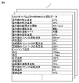
- FIG. 3 is a diagram showing an example of operation data reflecting the state of the air conditioning system 40.
- the operation data includes, for example, the outside air temperature, the discharge temperature, the evaporation temperature, the condensation temperature, the suction temperature, the blowout temperature, the high pressure, the low pressure, the operating frequency of the compressor 11, and the opening degree of the expansion valve 21.
- Operation mode operation state (operation, stop, or standby), rotation speed of each of the outdoor fan 14, the indoor fan 23, the temperature of the indoor space (set temperature) set by the user, the current value of the inverter of the compressor 11.
- the environment in which the air conditioning system 40 is operating has characteristics peculiar to the environment (for example, the length of the refrigerant pipe, the type of the indoor unit 20, the number of the indoor units 20, and the height difference between the indoor unit 20 and the outdoor unit 10). Can exist. Therefore, the determination criteria (for example, the threshold value) for detecting the abnormality of the air conditioning system 40 may differ depending on the environment in which the air conditioning system 40 operates. Therefore, if a common criterion is used regardless of the environment in which the air conditioning system 40 is operating, the accuracy of estimating the state of the air conditioning system 40 may decrease.
- the abnormality detection system 1 a learned model is generated in which the relationship between the operation data of the air conditioning system 40 and the specific parameters of the air conditioning system 40 is learned.
- the trained model it becomes possible to detect an abnormality in the air conditioning system 40 according to a determination standard suitable for the environment in which the air conditioning system 40 operates. As a result, the accuracy of estimating the state of the air conditioning system can be improved.
- FIG. 4 is a block diagram showing the configuration of the learning device 100 of FIG.
- the learning device 100 includes a data acquisition unit 110 (first data acquisition unit) and a model generation unit 120.
- the trained model storage unit 140 provided outside the learning device 100 includes an operating frequency estimation model M1 (specific model), an opening degree estimation model M2 (specific model), and a rotation speed estimation model M3 (specific model). Is saved.
- the trained model storage unit 140 may be formed inside the learning device 100. Further, at least one of the operating frequency estimation model M1, the opening degree estimation model M2, and the rotation speed estimation model M3 may be stored in the learned model storage unit 140.
- the operating frequency estimation model M1 is a regression model that receives parameters other than the operating frequency of the compressor 11 among the parameters included in the operating data of the air conditioning system 40 and outputs the operating frequency (specific parameter) of the compressor 11. ..
- the opening degree estimation model M2 is a regression model that receives parameters other than the opening degree of the expansion valve 21 among the parameters included in the operation data of the air conditioning system 40 and outputs the opening degree (specific parameter) of the expansion valve 21.
- the rotation speed estimation model M3 is a regression model that receives parameters other than the rotation speed of the outdoor fan 14 among the parameters included in the operation data of the air conditioning system 40 and outputs the rotation speed (specific parameter) of the outdoor fan 14.
- Each of the operating frequency estimation model M1, the opening degree estimation model M2, and the rotation speed estimation model M3 includes, for example, a neural network.
- the operating frequency of the compressor 11, the opening degree of the expansion valve 21, and the rotation speed of the outdoor fan 14 are basic operation amounts in VRF (Variable Refrigerant Flow) control.
- the data acquisition unit 110 acquires a plurality of operation data from the air conditioning system 40.
- the model generation unit 120 uses learning data created by using each of the plurality of operation data to determine the operation data, the operation frequency of the compressor 11, the opening degree of the expansion valve 21, and the rotation speed of the outdoor fan 14. Learn the relationship with each.
- the model generation unit 120 uses the learning data to use each of the operating frequency estimation model M1, the opening degree estimation model M2, and the rotation speed estimation model M3 as trained models.
- the acquisition period and acquisition interval of the operation data are arbitrary. Further, a general AI (Artificial Intelligence) technique can be applied to clustering and weighting of parameters included in operation data.
- AI Artificial Intelligence
- the learning algorithm used by the model generation unit 120 may be a known algorithm such as supervised learning, unsupervised learning, or reinforcement learning. In the following, a case where a neural network is applied will be described.
- the model generation unit 120 learns the relationship between the operation data, the operation frequency of the compressor 11, the opening degree of the expansion valve 21, and the rotation speed of the outdoor fan 14 by supervised learning according to, for example, a neural network model. do.
- supervised learning is to learn the features included in the learning data by giving the learning data, which is a set of input data (driving data) and correct answer data (label), to the learning device 100, and from the input. A method for inferring results.
- the correct answer data, the operating frequency of the compressor 11, the opening degree of the expansion valve 21, and the rotation speed of the outdoor fan 14 when the air conditioning system 40 is in a normal state for example, an accidental failure period
- the neural network of the regression model is composed of an input layer consisting of a plurality of neurons, an intermediate layer (hidden layer) consisting of a plurality of neurons, and an output layer consisting of one neuron.
- the intermediate layer may be one layer or two or more layers.
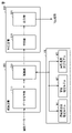
- FIG. 5 is a diagram showing an example of a neural network.
- the neural network Nw1 includes an input layer X10, an intermediate layer Y10, and an output layer Z10.
- the input layer X10 includes neurons X11, X12, X13.
- the intermediate layer Y10 contains neurons Y11 and Y12.
- the output layer Z10 contains neurons Z11.
- the input layer X10 and the intermediate layer Y10 are fully connected to each other.
- the intermediate layer Y10 and the output layer Z10 are fully coupled to each other.
- the values are multiplied by the weights w11 to w16 and input to the neurons Y11 and Y12 of the intermediate layer Y10.
- the outputs from the neurons Y11 and Y12 are multiplied by the weights w21 and w22 and output from the neuron Z11 in the output layer Z10.
- the output result from the output layer Z10 changes depending on the values of the weights w11 to w16, w21, and w22.
- Each neural network of the operation frequency estimation model M1, the opening degree estimation model M2, and the rotation speed estimation model M3 is supervised learning according to the learning data created by using the operation data acquired by the data acquisition unit 110. Learn the relationship between driving data and specific parameters corresponding to the model. That is, the weight and bias of the neural network of the model are for the error between the result and the correct data so that the result output from the output layer by inputting the operation data to the input layer approaches a specific parameter of the correct data. Updated by backpropagation.
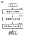
- FIG. 6 is a flowchart showing a learning process of the learning device 100 of FIG. In the following, the step is simply referred to as S.
- the data acquisition unit 110 acquires operation data.
- the model generation unit 120 uses supervised learning according to the learning data acquired by the data acquisition unit 110 to obtain the operation data, the operation frequency of the compressor 11, the opening degree of the expansion valve 21, and the rotation of the outdoor fan 14. The relationship with each of the speeds is learned, and each of the operating frequency estimation model M1, the opening degree estimation model M2, and the rotation speed estimation model M3 is used as a trained model.
- the model generation unit 120 stores the trained operating frequency estimation model M1, the trained opening degree estimation model M2, and the trained rotation speed estimation model M3 in the trained model storage unit 140, and performs learning processing. To finish.
- FIG. 7 is a diagram showing the correct answer data D1, D2, D3, D4, D5, D6, D7, D8 of the specific parameter together and the time chart RC1 of the specific parameter estimated by the trained model.
- the specific parameter is the operating frequency of the compressor 11
- Each of the points D1 to D8 represents the operating frequency of the compressor 11 when the air conditioning system 40 is in a normal state.
- the time chart RC1 is time series data of the operating frequency of the compressor 11 estimated by the trained operating frequency estimation model M1.
- the region SR1 represents a region where the operating frequency of the compressor 11 is normal.
- the normal region SR1 is set as a region in which the deviation rate from the time chart RC1 (estimated value of the trained model) is within the reference value (for example, 5%). For example, if the deviation rate is 5% or less and the operating frequency of the compressor 11 estimated by the trained operating frequency estimation model M1 is 100 Hz at a certain time, the normal region SR1 of the compressor 11 at that time is , 95 Hz or more and 105 Hz. When the operating frequency of the compressor 11 at that time is included in the range of 95 Hz or more and 105 Hz, it is determined that the state of the air conditioning system 40 is normal.
- the operating frequency of the compressor 11 at that time is not included in the range of 95 Hz or more and 105 Hz, it is determined that the state of the air conditioning system 40 is abnormal.
- the deviation rate from the estimated value of the trained model can be set by the user, and can be appropriately determined by an actual machine experiment or a simulation.
- the refrigerant shortage (during cooling) is the cause of the abnormality.
- the actual opening degree of the expansion valve 21 is smaller than the normal region, it is presumed that the causes of the abnormality are insufficient refrigerant (during heating), poor heat transfer of the outdoor unit 10, and poor heat transfer of the indoor unit 20.
- the causes of the abnormality are insufficient refrigerant (during heating), poor heat transfer of the outdoor unit 10, and the expansion valve 21. It is presumed that the opening does not open.
- the causes of the abnormality are insufficient refrigerant (during cooling) and defects that the opening degree of the expansion valve 21 does not close.
- FIG. 8 is a block diagram showing the configurations of the inference device 200 and the determination device 300 of FIG.
- the inference device 200 includes a data acquisition unit 210 (second data acquisition unit) and an inference unit 220.
- the determination device 300 includes a determination unit 310 and an output unit 320.
- the data acquisition unit 210 acquires operation data from the air conditioning system 40.
- the inference unit 220 estimates the operating frequency of the compressor 11, the opening degree of the expansion valve 21, and the rotation speed of the outdoor fan 14, respectively, using the trained models M1 to M3 stored in the trained model storage unit 140. do.
- the operating frequency of the compressor 11, the opening degree of the expansion valve 21, and the rotation speed of the outdoor fan 14 are estimated using the trained model learned in the model generation unit 120 of FIG.
- the configuration may be such that the operating frequency of the compressor 11, the opening degree of the expansion valve 21, and the rotation speed of the outdoor fan 14 are estimated using a trained model learned in another environment.
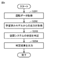
- FIG. 9 is a flowchart showing the inference processing of the inference device 200 of FIG. 8 and the determination processing of the determination device 300.
- the data acquisition unit 210 acquires the operation data of the air conditioning system 40.
- the inference unit 220 inputs operation data into the trained models M1 to M3 stored in the trained model storage unit 140, and inputs the operation frequency of the compressor 11, the opening degree of the expansion valve 21, and the outdoor fan 14. Get each.
- the determination unit 310 has the operating frequency of the compressor 11 output from the learned operating frequency estimation model M1, the opening degree of the expansion valve 21 output from the learned opening degree estimation model M2, and the learned operation frequency.
- the output unit 320 transmits the result of the determination made by the determination unit 310 in S203 to an external device (for example, a user's terminal device or a control device 30). If the determination result is abnormal, the output unit 320 may transmit the cause of the abnormality estimated together with the determination result to an external device.
- FIG. 10 is a diagram showing a time chart RC2 of a specific parameter estimated by the trained model, a normal region SR2 of the parameter, and a time chart AC of an actual specific parameter.
- the specific parameter is the operating frequency of the compressor 11
- the actual operating frequency of the compressor 11 is not included in the normal region SR2. After time t1, it is transmitted from the abnormality detection system 1 to an external device that an abnormality has occurred in the air conditioning system 40.
- FIG. 11 is a block diagram showing a hardware configuration of the abnormality detection system 1 of FIG.
- the abnormality detection system 1 includes a processing circuit 91, a memory 92 (storage unit), and an input / output unit 93.
- the processing circuit 91 includes a CPU (Central Processing Unit) that executes a program stored in the memory 92.
- the processing circuit 91 may include a GPU (Graphics Processing Unit).
- the function of the anomaly detection system 1 is realized by software, firmware, or a combination of software and firmware.
- the software or firmware is described as a program and stored in the memory 92.
- the processing circuit 91 reads out and executes the program stored in the memory 92.
- the CPU is also called a central processing unit, a processing unit, an arithmetic unit, a microprocessor, a microcomputer, a processor, or a DSP (Digital Signal Processor).
- DSP Digital Signal Processor
- the memory 92 includes a non-volatile or volatile semiconductor memory (for example, RAM (Random Access Memory), ROM (Read Only Memory), flash memory, EPROM (Erasable Programmable Read Only Memory), or EPROM (Electrically Erasable Programmable Read Only Memory). )), And includes magnetic discs, flexible discs, optical discs, compact discs, mini discs, or DVDs (Digital Versatile Discs).
- the memory 92 stores, for example, a trained model, an anomaly detection program, and a machine learning program.
- the input / output unit 93 receives an operation from the user and outputs the processing result to the user.
- the input / output unit 93 includes, for example, a mouse, a keyboard, a touch panel, a display, and a speaker.
- the learning algorithm is not limited to supervised learning.
- the learning algorithm it is also possible to apply reinforcement learning, unsupervised learning, semi-supervised learning, etc. in addition to supervised learning.
- model generation unit 120 As a learning algorithm used in the model generation unit 120, deep learning that learns the extraction of the feature amount itself can also be used, and other known methods such as neural networks, genetic programming, and functions can be used. Machine learning may be performed according to logical programming, support vector machines, and the like.
- the learning device 100 and the inference device 200 are connected to the air conditioning system 40 via the network 900 as a device separate from the air conditioning system 40, but the learning device 100 and the inference device 200 have been described. May be built into the air conditioning system 40. Further, the learning device 100 and the inference device 200 may exist on the cloud server.
- the learning device and the inference device according to the embodiment, it is possible to improve the estimation accuracy of the state of the air conditioning system.
- 1 Abnormality detection system 10 outdoor unit, 11 compressor, 12 outdoor heat exchanger, 13 four-way valve, 14 outdoor fan, 20 indoor unit, 21 expansion valve, 22 indoor heat exchanger, 23 indoor fan, 30 control device, 40 Air conditioning system, 50-54 temperature sensor, 61, 62 pressure sensor, 91 processing circuit, 92 memory, 93 input / output unit, 100 learning device, 110, 210 data acquisition unit, 120 model generation unit, 140 trained model storage unit, 200 inference device, 220 inference unit, 300 judgment device, 310 judgment unit, 320 output unit, 900 network, M1 operating frequency estimation model, M2 opening estimation model, M3 rotation speed estimation model, Nw1 neural network.
Landscapes
- Engineering & Computer Science (AREA)
- Mechanical Engineering (AREA)
- General Engineering & Computer Science (AREA)
- Chemical & Material Sciences (AREA)
- Combustion & Propulsion (AREA)
- Signal Processing (AREA)
- Physics & Mathematics (AREA)
- Fuzzy Systems (AREA)
- Mathematical Physics (AREA)
- Health & Medical Sciences (AREA)
- Biomedical Technology (AREA)
- Thermal Sciences (AREA)
- Human Computer Interaction (AREA)
- Air Conditioning Control Device (AREA)
Abstract
学習装置(100)は、冷媒が循環する空調システムの状態を学習する。空調システムは、室外機と、少なくとも1つの室内機とを含む。学習装置(100)は、第1データ取得部(110)と、モデル生成部(120)とを備える。第1データ取得部(110)は、空調システムの運転データを取得する。モデル生成部(120)は、運転データを用いて、特定モデル(M1~M3)を学習済みモデルとする。運転データは、第2熱交換器を通過する空気の温度、冷媒の温度および圧力、ならびに少なくとも1つの室内機の各々が配置された空間外の温度の少なくとも1つと、特定パラメータとを含む。特定モデル(M1~M3)は、特定パラメータ以外の運転データから、特定パラメータを推定する。特定パラメータは、圧縮機の運転周波数、膨張弁の開度、および送風装置の単位時間当たりの送風量の少なくとも1つを含む。
Description
本開示は、空調システムの状態の学習装置および推論装置に関する。
従来、空調システムの異常を検知する装置が知られている。たとえば、特開2017-221023号公報(特許文献1)には、電気ノイズの影響を受けにくいq軸電流を分析することにより、圧縮機の内部状態を正確に推定する故障徴候検出装置が開示されている。当該故障徴候検出装置によれば、圧縮機の異常の検出精度を向上させることができる。
特許文献1には、FFT(Fast Fourier Transform)解析の結果、圧縮機の運転周波数成分の強度が閾値を超えた場合に圧縮機の異常が検出されることが開示されている。しかし、当該閾値は、空調システムが運転している環境毎に異なり得るため、空調システムが運転している環境によらずに共通の閾値が用いられる場合、空調システムの状態の推定精度が低下し得る。
本開示は、上述のような課題を解決するためになされたものであり、その目的は、空調システムの状態の推定精度を向上させることである。
本開示の一局面に係る学習装置は、冷媒が循環する空調システムの状態を学習する。空調システムは、室外機と、少なくとも1つの室内機とを含む。室外機は、圧縮機と、第1熱交換器と、第1熱交換器に送風する送風装置とを含む。少なくとも1つの室内機の各々は、膨張弁と、第2熱交換器とを含む。冷媒は、圧縮機、第1熱交換器、膨張弁、および第2熱交換器の順に循環するか、または圧縮機、第2熱交換器、膨張弁、および第1熱交換器の順に循環する。学習装置は、第1データ取得部と、モデル生成部とを備える。第1データ取得部は、空調システムの運転データを取得する。モデル生成部は、運転データを用いて、特定モデルを学習済みモデルとする。運転データは、第2熱交換器を通過する空気の温度、冷媒の温度および圧力、ならびに少なくとも1つの室内機の各々が配置された空間外の温度の少なくとも1つと、特定パラメータとを含む。特定モデルは、特定パラメータ以外の運転データから、特定パラメータを推定する。特定パラメータは、圧縮機の運転周波数、膨張弁の開度、および送風装置の単位時間当たりの送風量の少なくとも1つを含む。
本開示の他の局面に係る推論装置は、学習済みの特定モデルを用いて、冷媒が循環する空調システムの状態を推論する。空調システムは、室外機と、少なくとも1つの室内機とを含む。室外機は、圧縮機と、第1熱交換器と、第1熱交換器に送風する送風装置とを含む。少なくとも1つの室内機の各々は、膨張弁と、第2熱交換器とを含む。冷媒は、圧縮機、第1熱交換器、膨張弁、および第2熱交換器の順に循環するか、または圧縮機、第2熱交換器、膨張弁、および第1熱交換器の循環方向の順に循環する。推論装置は、データ取得部と、推論部とを備える。データ取得部は、空調システムの運転データを取得する。推論部は、特定モデルを用いて運転データから特定パラメータを推定する。運転データは、第2熱交換器と熱交換をする空気の温度、冷媒の温度および圧力、ならびに少なくとも1つの室内機の各々が配置された空間外の温度の少なくとも1つを含む。特定パラメータは、圧縮機の運転周波数、膨張弁の開度、および送風装置の単位時間当たりの送風量の少なくとも1つを含む。
本開示に係る学習装置および推論装置によれば、運転データが第2熱交換器と熱交換をする空気の温度、冷媒の温度および圧力、ならびに少なくとも1つの室内機の各々が配置された空間外の温度の少なくとも1つを含むことにより、空調システムの状態の推定精度を向上させることができる。
以下、本開示の実施の形態について、図面を参照しながら詳細に説明する。なお、図中同一または相当部分には同一符号を付してその説明は原則として繰り返さない。
図1は、実施の形態に係る学習装置100および推論装置200を備える異常検知システム1、および異常検知システム1によって状態が監視される空調システム40の構成の一例を示すブロック図である。図1に示されるように、異常検知システム1は、ネットワーク900を介して空調システム40に接続されている。
異常検知システム1は、学習装置100と、推論装置200と、判定装置300とを備える。空調システム40は、複数の室内機20と、室外機10と、制御装置30とを備える。複数の室内機20の各々は、室内空間に配置され、室外機10と接続されている。室外機10は、室内空間の外部の空間(室外空間)に配置されている。なお、空調システム40に含まれる室内機20の数は、1であってもよい。
室外機10は、圧縮機と、室外熱交換器(第1熱交換器)と、室外ファン(送風装置)とを含む。複数の室内機20の各々は、膨張弁と、室内熱交換器(第2熱交換器)とを含む。室外機10に含まれる圧縮機から複数の室内機20の各々に冷媒が供給される。当該冷媒は、複数の室内機20の各々と室外機10との間を循環する。
制御装置30は、サーモスタットを含み、空調システム40を統合的に制御する。制御装置30は、ネットワーク900を介して異常検知システム1に接続されている。ネットワーク900は、インターネットおよびクラウドシステムを含む。
図2は、図1の空調システム40の構成を示す機能ブロック図である。図2に示されるように、室外機10は、圧縮機11と、室外熱交換器12(第1熱交換器)と、四方弁13と、室外ファン14(送風装置)と、温度センサ51,52と、圧力センサ61,62とを含む。複数の室内機20の各々は、膨張弁21と、室内熱交換器22(第2熱交換器)と、室内ファン23と、温度センサ53,54とを含む。温度センサ50は、室外空間に配置されている。なお、膨張弁21は、たとえばLEV(Linear Expansion Valve)を含む。また、温度センサ50~54の各々は、サーミスタを含む。
空調システム40の運転モードには、暖房モード、冷房モード、および除霜モードが含まれる。暖房モードにおいて四方弁13は、圧縮機11の吐出口と室内熱交換器22とを接続するとともに、室外熱交換器12と圧縮機11の吸入口とを接続する。暖房モードにおいて冷媒は、圧縮機11、四方弁13、室内熱交換器22、膨張弁21、および室外熱交換器12の順に循環する。冷房モードおよび除霜モードにおいて四方弁13は、圧縮機11の吐出口と室外熱交換器12とを接続するとともに、室内熱交換器22と圧縮機11の吸入口とを接続する。冷房モードおよび除霜モードにおいて冷媒は、圧縮機11、四方弁13、室外熱交換器12、膨張弁21、および室内熱交換器22の順に循環する。
温度センサ50は、室外空間の温度(外気温度)を測定して、外気温度を制御装置30に出力する。温度センサ51は、圧縮機11から吐出される冷媒の温度(吐出温度)を測定し、吐出温度を制御装置30に出力する。温度センサ52は、室外熱交換器12を通過する冷媒の温度(蒸発温度または凝縮温度)を測定し、当該温度を制御装置30に出力する。温度センサ53は、室内熱交換器22を通過する冷媒の温度(凝縮温度または蒸発温度)を測定し、当該温度を制御装置30に出力する。温度センサ54は、室内熱交換器22を通過する空気の温度(吸込温度または吹出温度)を測定し、当該温度を制御装置30に出力する。圧力センサ61は、圧縮機11から吐出される冷媒の圧力(高圧)を測定し、高圧を制御装置30に出力する。圧力センサ62は、圧縮機11に吸入される冷媒の圧力(低圧)を測定し、低圧を制御装置30に出力する。
制御装置30は、圧縮機11の運転周波数を制御して、圧縮機11が単位時間当たりに吐出する冷媒量を制御する。制御装置30は、膨張弁21の開度を制御する。制御装置30は、四方弁13を制御して、冷媒の循環方向を切り替える。制御装置30は、室外ファン14および室内ファン23の各々の回転速度を制御して、当該ファンの単位時間当たりの送風量を制御する。制御装置30は、空調システムの状態を反映する運転データを測定時刻と関連付けて異常検知システムに送信する。
図3は、空調システム40の状態を反映する運転データの一例を示す図である。図3に示されるように、運転データには、たとえば、外気温度、吐出温度、蒸発温度、凝縮温度、吸込温度、吹出温度、高圧、低圧、圧縮機11の運転周波数、膨張弁21の開度、運転モード、運転状態(運転、停止、または待機)、室外ファン14,室内ファン23の各々の回転速度、ユーザによって設定された室内空間の温度(設定温度)、圧縮機11のインバータの電流値、当該インバータの電圧値、室外機10に含まれるヒートシンクの温度、および室外機10と室内機20とを接続する液管(液体の冷媒が流れる配管)の温度(液管温度)が含まれる。
空調システム40が運転している環境には、当該環境に特有の特性(たとえば、冷媒配管長、室内機20の種類、室内機20の数、および室内機20と室外機10との高低差)が存在し得る。そのため、空調システム40の異常を検知するための判定基準(たとえば閾値)は、空調システム40が運転する環境毎に異なり得る。したがって、空調システム40が運転している環境によらずに共通の判定基準が用いられる場合、空調システム40の状態の推定精度が低下し得る。
そこで、異常検知システム1においては、空調システム40の運転データと空調システム40の特定パラメータとの関係を学習した学習済みモデルを生成する。当該学習済みモデルを用いることにより、空調システム40が運転する環境に適合した判定基準によって空調システム40の異常を検知することが可能になる。その結果、空調システムの状態の推定精度を向上させることができる。
図4は、図1の学習装置100の構成を示すブロック図である。図4に示されるように、学習装置100は、データ取得部110(第1データ取得部)と、モデル生成部120とを備える。学習装置100の外部に設けられた学習済みモデル記憶部140には、運転周波数推定モデルM1(特定モデル)と、開度推定モデルM2(特定モデル)と、回転速度推定モデルM3(特定モデル)とが保存されている。なお、学習済みモデル記憶部140は、学習装置100の内部に形成されてもよい。また、学習済みモデル記憶部140には、運転周波数推定モデルM1、開度推定モデルM2、および回転速度推定モデルM3のうち少なくとも1つが保存されていればよい。
運転周波数推定モデルM1は、空調システム40の運転データに含まれるパラメータのうち、圧縮機11の運転周波数以外のパラメータを受けて、圧縮機11の運転周波数(特定パラメータ)を出力する回帰モデルである。開度推定モデルM2は、空調システム40の運転データに含まれるパラメータのうち、膨張弁21の開度以外のパラメータを受けて膨張弁21の開度(特定パラメータ)を出力する回帰モデルである。回転速度推定モデルM3は、空調システム40の運転データに含まれるパラメータのうち、室外ファン14の回転速度以外のパラメータを受けて室外ファン14の回転速度(特定パラメータ)を出力する回帰モデルである。運転周波数推定モデルM1、開度推定モデルM2、および回転速度推定モデルM3の各々は、たとえばニューラルネットワークを含む。なお、圧縮機11の運転周波数、膨張弁21の開度、および室外ファン14の回転速度は、VRF(Variable Refrigerant Flow)制御における基本的な操作量である。
データ取得部110は、空調システム40から複数の運転データを取得する。モデル生成部120は、複数の運転データの各々を用いて作成される学習データを用いて、運転データと、圧縮機11の運転周波数、膨張弁21の開度、および室外ファン14の回転速度の各々との関係を学習する。モデル生成部120は、当該学習データを用いて運転周波数推定モデルM1、開度推定モデルM2、および回転速度推定モデルM3の各々を学習済みモデルとする。なお、運転データの取得期間および取得間隔は任意である。また、運転データに含まれるパラメータのクラスタリングおよび重み付けには一般的なAI(Artificial Intelligence)技術が適用可能である。
モデル生成部120が用いる学習アルゴリズムは、教師あり学習、教師なし学習、または強化学習等の公知のアルゴリズムであってもよい。以下では、ニューラルネットワークを適用する場合について説明する。
モデル生成部120は、たとえば、ニューラルネットワークモデルに従って、教師あり学習により、運転データと、圧縮機11の運転周波数、膨張弁21の開度、および室外ファン14の回転速度の各々との関係を学習する。ここで、教師あり学習とは、入力データ(運転データ)と正解データ(ラベル)の組である学習データを学習装置100に与えることで、それらの学習データに含まれる特徴を学習し、入力から結果を推論する手法をいう。正解データとしては、空調システム40が正常な状態である場合(たとえば偶発故障期間)における圧縮機11の運転周波数、膨張弁21の開度、および室外ファン14の回転速度を用いることができる。
回帰モデルのニューラルネットワークは、複数のニューロンからなる入力層、複数のニューロンからなる中間層(隠れ層)、および1つのニューロンからなる出力層で構成される。中間層は、1層、または2層以上でもよい。
図5は、ニューラルネットワークの一例を示す図である。図5に示されるように、ニューラルネットワークNw1は、入力層X10と、中間層Y10と、出力層Z10とを含む。入力層X10は、ニューロンX11,X12,X13を含む。中間層Y10は、ニューロンY11,Y12を含む。出力層Z10は、ニューロンZ11を含む。入力層X10と中間層Y10とは、互いに全結合している。中間層Y10と出力層Z10とは互いに全結合している。
複数の入力が入力層X10のニューロンX11~X13にそれぞれに入力されると、その値に重みw11~w16が乗じられて中間層Y10のニューロンY11,Y12に入力される。ニューロンY11,Y12からの出力に重みw21,w22が乗じられて出力層Z10のニューロンZ11から出力される。出力層Z10からの出力結果は、重みw11~w16,w21,w22の値によって変わる。
運転周波数推定モデルM1、開度推定モデルM2、および回転速度推定モデルM3の各々のニューラルネットワークは、データ取得部110によって取得される運転データを用いて作成される学習データに従って、教師あり学習により、運転データと当該モデルに対応する特定パラメータとの関係を学習する。すなわち、当該モデルのニューラルネットワークの重みおよびバイアスは、入力層に運転データを入力して出力層から出力された結果が、正解データの特定パラメータに近づくように、当該結果と正解データとの誤差に対するバックプロパゲーションによって更新される。
図6は、図4の学習装置100の学習処理を示すフローチャートである。以下ではステップを単にSと記載する。図6に示されるように、S101において、データ取得部110は、運転データを取得する。
S102において、モデル生成部120は、データ取得部110によって取得された学習データに従って、教師あり学習により、運転データと、圧縮機11の運転周波数、膨張弁21の開度、および室外ファン14の回転速度の各々との関係を学習し、運転周波数推定モデルM1、開度推定モデルM2、および回転速度推定モデルM3の各々を学習済みモデルとする。
S103において、モデル生成部120は、学習済みの運転周波数推定モデルM1、学習済みの開度推定モデルM2、および学習済みの回転速度推定モデルM3を学習済みモデル記憶部140に保存して、学習処理を終了する。
図7は、特定パラメータの正解データD1,D2,D3,D4,D5,D6,D7、D8と、学習済みモデルによって推定される特定パラメータのタイムチャートRC1とを併せて示す図である。図7においては、特定パラメータが圧縮機11の運転周波数である場合について説明する。点D1~D8の各々は、空調システム40が正常な状態である場合の圧縮機11の運転周波数を表す。タイムチャートRC1は、学習済みの運転周波数推定モデルM1によって推定された圧縮機11の運転周波数の時系列データである。領域SR1は、圧縮機11の運転周波数が正常である領域を表す。正常領域SR1は、タイムチャートRC1(学習済みモデルの推定値)からの乖離率が基準値(たとえば5%)以内の領域として設定される。たとえば、乖離率が5%以下であり、学習済みの運転周波数推定モデルM1によって推定された圧縮機11の運転周波数が或る時刻において100Hzである場合、当該時刻における圧縮機11の正常領域SR1は、95Hz以上105Hzの範囲である。当該時刻における圧縮機11の運転周波数が95Hz以上105Hzの範囲に含まれる場合、空調システム40の状態が正常であると判定される。当該時刻における圧縮機11の運転周波数が95Hz以上105Hzの範囲に含まれない場合、空調システム40の状態が異常であると判定される。膨張弁21の開度および室外ファン14の回転速度についても同様である。なお、学習済みモデルの推定値からの乖離率は、ユーザが設定することが可能であり、実機実験あるいはシミュレーションによって適宜決定することが可能である。
圧縮機11の実際の運転周波数が、推定された圧縮機11の運転周波数の正常領域より高い場合、異常原因として、冷媒不足、室外機10の伝熱不良、および膨張弁21の開度が閉じないという不良が推定される。また、圧縮機11の実際の運転周波数が正常領域SR1よりも低い場合、異常原因として、冷媒不足、室内機20の伝熱不良、膨張弁21の開度が開かないという不良が推定される。
膨張弁21の実際の開度が、推定された膨張弁21の開度の正常領域より大きい場合、異常原因として、冷媒不足(冷房時)が推定される。膨張弁21の実際の開度が正常領域より小さい場合、異常原因として、冷媒不足(暖房時)、室外機10の伝熱不良、および室内機20の伝熱不良が推定される。
室外ファン14の実際の回転速度が、推定された室外ファン14の回転速度の正常領域より速い場合、異常原因として、冷媒不足(暖房時)、室外機10の伝熱不良、および膨張弁21の開度が開かないという不良が推定される。室外ファン14の実際の回転速度が正常領域より遅い場合、異常原因として、冷媒不足(冷房時)、および膨張弁21の開度が閉じないという不良が推定される。
図8は、図1の推論装置200および判定装置300の構成を示すブロック図である。推論装置200は、データ取得部210(第2データ取得部)と、推論部220とを含む。判定装置300は、判定部310と、出力部320とを含む。
データ取得部210は、空調システム40から運転データを取得する。推論部220は、学習済みモデル記憶部140に記憶されている学習済みモデルM1~M3を利用して圧縮機11の運転周波数、膨張弁21の開度、および室外ファン14の回転速度をそれぞれ推定する。なお、実施の形態では、図4のモデル生成部120において学習された学習済みモデルを用いて圧縮機11の運転周波数、膨張弁21の開度、および室外ファン14の回転速度を推定する構成を説明したが、他の環境で学習された学習済みモデルを用いて圧縮機11の運転周波数、膨張弁21の開度、および室外ファン14の回転速度が推定される構成としてもよい。
図9は、図8の推論装置200の推論処理および判定装置300の判定処理を併せて示すフローチャートである。図9に示されように、S201において、データ取得部210は、空調システム40の運転データを取得する。S202において、推論部220は、学習済みモデル記憶部140に記憶された学習済みモデルM1~M3に運転データを入力し、圧縮機11の運転周波数、膨張弁21の開度、および室外ファン14をそれぞれ取得する。S203において、判定部310は、学習済みの運転周波数推定モデルM1から出力された圧縮機11の運転周波数、学習済みの開度推定モデルM2から出力された膨張弁21の開度、および学習済みの回転速度推定モデルM3から出力された室外ファン14の回転速度を用いて、空調システム40の状態が正常か異常かを判定する。判定部310は、たとえば、圧縮機11の運転周波数、膨張弁21の開度、および室外ファン14の回転速度のいずれか一つが正常範囲に含まれていない場合に空調システム40の状態が異常であると判定する。S204において、出力部320は、S203において判定部310によって行われた判定の結果を、外部の装置(たとえば、ユーザの端末装置、または制御装置30)に送信する。出力部320は、判定の結果が異常である場合、判定結果とともに推定される異常原因を外部の装置に送信してもよい。
図10は、学習済みモデルによって推定される特定パラメータのタイムチャートRC2、当該パラメータの正常領域SR2、および実際の特定パラメータのタイムチャートACを併せて示す図である。図10においては、特定パラメータが圧縮機11の運転周波数である場合について説明する。図10に示されるように、時刻t1以降において、圧縮機11の実際の運転周波数が正常領域SR2に含まれていない。時刻t1以降において、空調システム40に異常が発生していることが異常検知システム1から外部の装置に送信される。
図11は、図1の異常検知システム1のハードウェア構成を示すブロック図である。図11に示されるように、異常検知システム1は、処理回路91と、メモリ92(記憶部)と、入出力部93とを含む。処理回路91は、メモリ92に格納されるプログラムを実行するCPU(Central Processing Unit)を含む。処理回路91は、GPU(Graphics Processing Unit)を含んでもよい。異常検知システム1の機能は、ソフトウェア、ファームウェア、またはソフトウェアとファームウェアとの組み合わせにより実現される。ソフトウェアあるいはファームウェアはプログラムとして記述され、メモリ92に格納される。処理回路91は、メモリ92に記憶されたプログラムを読み出して実行する。なお、CPUは、中央処理装置、処理装置、演算装置、マイクロプロセッサ、マイクロコンピュータ、プロセッサ、あるいはDSP(Digital Signal Processor)とも呼ばれる。
メモリ92には、不揮発性または揮発性の半導体メモリ(たとえばRAM(Random Access Memory)、ROM(Read Only Memory)、フラッシュメモリ、EPROM(Erasable Programmable Read Only Memory)、あるいはEEPROM(Electrically Erasable Programmable Read Only Memory))、および磁気ディスク、フレキシブルディスク、光ディスク、コンパクトディスク、ミニディスク、あるいはDVD(Digital Versatile Disc)が含まれる。メモリ92には、たとえば、学習済みモデル、異常検知プログラム、および機械学習プログラムが保存される。
入出力部93は、ユーザからの操作を受けるとともに、処理結果をユーザに出力する。入出力部93は、たとえば、マウス、キーボード、タッチパネル、ディスプレイ、およびスピーカを含む。
なお、実施の形態では、モデル生成部120が用いる学習アルゴリズムに教師あり学習を適用した場合について説明したが、学習アルゴリズムは教師あり学習に限られるものではない。学習アルゴリズムについては、教師あり学習以外にも、強化学習、教師なし学習、または半教師あり学習等を適用することも可能である。
また、モデル生成部120に用いられる学習アルゴリズムとしては、特徴量そのものの抽出を学習する、深層学習(Deep Learning)を用いることもでき、他の公知の方法、たとえばニューラルネットワーク、遺伝的プログラミング、機能論理プログラミング、もしくはサポートベクターマシンなどに従って機械学習が実行されてもよい。
なお、実施の形態においては、学習装置100および推論装置200が、ネットワーク900を介して空調システム40に接続される、空調システム40とは別個の装置として説明したが、学習装置100および推論装置200は空調システム40に内蔵されていてもよい。また、学習装置100および推論装置200は、クラウドサーバ上に存在していてもよい。
以上、実施の形態に係る学習装置および推論装置によれば、空調システムの状態の推定精度を向上させることができる。
今回開示された実施の形態はすべての点で例示であって制限的なものではないと考えられるべきである。本開示の範囲は上記した説明ではなくて請求の範囲によって示され、請求の範囲と均等の意味および範囲内でのすべての変更が含まれることが意図される。
1 異常検知システム、10 室外機、11 圧縮機、12 室外熱交換器、13 四方弁、14 室外ファン、20 室内機、21 膨張弁、22 室内熱交換器、23 室内ファン、30 制御装置、40 空調システム、50~54 温度センサ、61,62 圧力センサ、91 処理回路、92 メモリ、93 入出力部、100 学習装置、110,210 データ取得部、120 モデル生成部、140 学習済みモデル記憶部、200 推論装置、220 推論部、300 判定装置、310 判定部、320 出力部、900 ネットワーク、M1 運転周波数推定モデル、M2 開度推定モデル、M3 回転速度推定モデル、Nw1 ニューラルネットワーク。
Claims (6)
- 冷媒が循環する空調システムの状態を学習する学習装置であって、
前記空調システムは、室外機と、少なくとも1つの室内機とを含み、
前記室外機は、圧縮機と、第1熱交換器と、前記第1熱交換器に送風する送風装置とを含み、
前記少なくとも1つの室内機の各々は、膨張弁と、第2熱交換器とを含み、
前記冷媒は、前記圧縮機、前記第1熱交換器、前記膨張弁、および前記第2熱交換器の順に循環するか、または前記圧縮機、前記第2熱交換器、前記膨張弁、および前記第1熱交換器の順に循環し、
前記学習装置は、
前記空調システムの運転データを取得する第1データ取得部と、
前記運転データを用いて、特定モデルを学習済みモデルとするモデル生成部とを備え、
前記運転データは、前記第2熱交換器を通過する空気の温度、前記冷媒の温度および圧力、ならびに前記少なくとも1つの室内機の各々が配置された空間外の温度の少なくとも1つと、特定パラメータとを含み、
前記特定モデルは、前記特定パラメータ以外の前記運転データから、前記特定パラメータを推定し、
前記特定パラメータは、前記圧縮機の運転周波数、前記膨張弁の開度、および前記送風装置の単位時間当たりの送風量の少なくとも1つを含む、学習装置。 - 前記空調システムが正常な状態である場合の前記運転データを正解データとして、前記モデル生成部は、前記特定モデルに対して教師あり学習を行う、請求項1に記載の学習装置。
- 前記運転データを取得する第2データ取得部と、
請求項1または2に記載の学習装置によって生成された学習済みの前記特定モデルを用いる推論部とを備え、
前記推論部は、学習済みの前記特定モデルを用いて前記第2データ取得部によって取得された前記運転データから前記特定パラメータを推定する、推論装置。 - 学習済みの特定モデルを用いて、冷媒が循環する空調システムの状態を推論する推論装置であって、
前記空調システムは、室外機と、少なくとも1つの室内機とを含み、
前記室外機は、圧縮機と、第1熱交換器と、前記第1熱交換器に送風する送風装置とを含み、
前記少なくとも1つの室内機の各々は、膨張弁と、第2熱交換器とを含み、
前記冷媒は、前記圧縮機、前記第1熱交換器、前記膨張弁、および前記第2熱交換器の順に循環するか、または前記圧縮機、前記第2熱交換器、前記膨張弁、および前記第1熱交換器の順に循環し、
前記推論装置は、
前記空調システムの運転データを取得するデータ取得部と、
前記特定モデルを用いて前記運転データから特定パラメータを推定する推論部とを備え、
前記運転データは、前記第2熱交換器と熱交換をする空気の温度、前記冷媒の温度および圧力、ならびに前記少なくとも1つの室内機の各々が配置された空間外の温度の少なくとも1つを含み、
前記特定パラメータは、前記圧縮機の運転周波数、前記膨張弁の開度、および前記送風装置の単位時間当たりの送風量の少なくとも1つを含む、推論装置。 - 前記特定モデルの各々は、教師あり学習によって生成される、請求項4に記載の推論装置。
- 前記推論部によって推定された前記特定パラメータと、前記特定パラメータに対応する実際の運転データとを用いて、前記空調システムが正常か異常かの判定を行い、前記判定の結果を出力する判定部をさらに備える、請求項4または5に記載の推論装置。
Priority Applications (4)
| Application Number | Priority Date | Filing Date | Title |
|---|---|---|---|
| US18/245,015 US20230358431A1 (en) | 2020-12-11 | 2020-12-11 | Learning device and inference device for state of air conditioning system |
| EP20965168.6A EP4261470A4 (en) | 2020-12-11 | 2020-12-11 | LEARNING DEVICE AND INFERENCE DEVICE FOR THE STATE OF AN AIR CONDITIONING SYSTEM |
| JP2022568024A JPWO2022123787A1 (ja) | 2020-12-11 | 2020-12-11 | |
| PCT/JP2020/046363 WO2022123787A1 (ja) | 2020-12-11 | 2020-12-11 | 空調システムの状態の学習装置および推論装置 |
Applications Claiming Priority (1)
| Application Number | Priority Date | Filing Date | Title |
|---|---|---|---|
| PCT/JP2020/046363 WO2022123787A1 (ja) | 2020-12-11 | 2020-12-11 | 空調システムの状態の学習装置および推論装置 |
Publications (1)
| Publication Number | Publication Date |
|---|---|
| WO2022123787A1 true WO2022123787A1 (ja) | 2022-06-16 |
Family
ID=81974289
Family Applications (1)
| Application Number | Title | Priority Date | Filing Date |
|---|---|---|---|
| PCT/JP2020/046363 WO2022123787A1 (ja) | 2020-12-11 | 2020-12-11 | 空調システムの状態の学習装置および推論装置 |
Country Status (4)
| Country | Link |
|---|---|
| US (1) | US20230358431A1 (ja) |
| EP (1) | EP4261470A4 (ja) |
| JP (1) | JPWO2022123787A1 (ja) |
| WO (1) | WO2022123787A1 (ja) |
Citations (4)
| Publication number | Priority date | Publication date | Assignee | Title |
|---|---|---|---|---|
| JPH0719567A (ja) * | 1993-07-02 | 1995-01-20 | Toshiba Corp | 空気調和機 |
| JP2006343063A (ja) * | 2005-06-10 | 2006-12-21 | Daikin Ind Ltd | 設備機器の異常予知システム、設備機器の異常予知装置および設備機器の異常予知方法 |
| JP2014214970A (ja) * | 2013-04-25 | 2014-11-17 | 三菱電機株式会社 | 空気調和装置及び空気調和装置監視システム |
| JP2017221023A (ja) | 2016-06-07 | 2017-12-14 | 三菱電機株式会社 | 空調機の故障徴候検出装置 |
Family Cites Families (2)
| Publication number | Priority date | Publication date | Assignee | Title |
|---|---|---|---|---|
| JP6932264B2 (ja) * | 2018-08-15 | 2021-09-08 | 三菱電機株式会社 | 空調装置、制御装置、空調方法及びプログラム |
| JP2020153574A (ja) * | 2019-03-19 | 2020-09-24 | ダイキン工業株式会社 | 情報処理装置、空気調和装置、情報処理方法、空気調和方法、及びプログラム |
-
2020
- 2020-12-11 US US18/245,015 patent/US20230358431A1/en active Pending
- 2020-12-11 EP EP20965168.6A patent/EP4261470A4/en active Pending
- 2020-12-11 JP JP2022568024A patent/JPWO2022123787A1/ja active Pending
- 2020-12-11 WO PCT/JP2020/046363 patent/WO2022123787A1/ja unknown
Patent Citations (4)
| Publication number | Priority date | Publication date | Assignee | Title |
|---|---|---|---|---|
| JPH0719567A (ja) * | 1993-07-02 | 1995-01-20 | Toshiba Corp | 空気調和機 |
| JP2006343063A (ja) * | 2005-06-10 | 2006-12-21 | Daikin Ind Ltd | 設備機器の異常予知システム、設備機器の異常予知装置および設備機器の異常予知方法 |
| JP2014214970A (ja) * | 2013-04-25 | 2014-11-17 | 三菱電機株式会社 | 空気調和装置及び空気調和装置監視システム |
| JP2017221023A (ja) | 2016-06-07 | 2017-12-14 | 三菱電機株式会社 | 空調機の故障徴候検出装置 |
Non-Patent Citations (1)
| Title |
|---|
| See also references of EP4261470A4 |
Also Published As
| Publication number | Publication date |
|---|---|
| EP4261470A1 (en) | 2023-10-18 |
| US20230358431A1 (en) | 2023-11-09 |
| JPWO2022123787A1 (ja) | 2022-06-16 |
| EP4261470A4 (en) | 2024-04-03 |
Similar Documents
| Publication | Publication Date | Title |
|---|---|---|
| Eom et al. | Refrigerant charge fault detection method of air source heat pump system using convolutional neural network for energy saving | |
| Karami et al. | Fault detection and diagnosis for nonlinear systems: A new adaptive Gaussian mixture modeling approach | |
| Shi et al. | Refrigerant charge fault diagnosis in the VRF system using Bayesian artificial neural network combined with ReliefF filter | |
| KR100368703B1 (ko) | 팽창밸브모니터링시스템 | |
| JP5820375B2 (ja) | データセンタ冷却ユニットを効率的に調整する方法及び装置 | |
| JP6004228B2 (ja) | 空気調和機 | |
| Ranade et al. | A computationally efficient method for fault diagnosis of fan-coil unit terminals in building Heating Ventilation and Air Conditioning systems | |
| JPH1183246A (ja) | 冷媒充てん量を監視する方法 | |
| Gao et al. | Fault detection and diagnosis method for cooling dehumidifier based on LS-SVM NARX model | |
| CN110657552A (zh) | 故障检测方法、换热系统及计算机可读存储介质 | |
| JP2020153574A (ja) | 情報処理装置、空気調和装置、情報処理方法、空気調和方法、及びプログラム | |
| Du et al. | Deep learning GAN-based data generation and fault diagnosis in the data center HVAC system | |
| WO2021192279A1 (ja) | 空調制御の学習装置および推論装置 | |
| JP7367472B2 (ja) | 推定方法、推定装置及びプログラム | |
| WO2022123787A1 (ja) | 空調システムの状態の学習装置および推論装置 | |
| JP2005301582A (ja) | プロセス管理装置 | |
| KR20210063970A (ko) | 공기 조화기 및 그 제어 방법 | |
| Chen et al. | Similarity learning-based fault detection and diagnosis in building HVAC systems with limited labeled data | |
| CN114761732B (zh) | 模型共享系统、模型管理装置以及空调装置的控制装置 | |
| JP7006859B2 (ja) | 空調制御装置、空調システム、空調制御方法、空調制御プログラム | |
| WO2023223557A1 (ja) | 空調システムの異常を検知するシステムおよび方法 | |
| CN112128922A (zh) | 多联机空调系统的温控方法及装置 | |
| WO2021229768A1 (ja) | 空調機器のメンテナンスの学習装置および推論装置 | |
| WO2022101989A1 (ja) | 空気調和装置、および空気調和装置の学習装置 | |
| JP7093031B2 (ja) | 情報処理装置、情報処理方法、及びプログラム |
Legal Events
| Date | Code | Title | Description |
|---|---|---|---|
| 121 | Ep: the epo has been informed by wipo that ep was designated in this application |
Ref document number: 20965168 Country of ref document: EP Kind code of ref document: A1 |
|
| ENP | Entry into the national phase |
Ref document number: 2022568024 Country of ref document: JP Kind code of ref document: A |
|
| NENP | Non-entry into the national phase |
Ref country code: DE |
|
| ENP | Entry into the national phase |
Ref document number: 2020965168 Country of ref document: EP Effective date: 20230711 |