WO2022123728A1 - 情報処理装置、情報処理システム、情報処理端末、情報処理方法及びプログラム - Google Patents
情報処理装置、情報処理システム、情報処理端末、情報処理方法及びプログラム Download PDFInfo
- Publication number
- WO2022123728A1 WO2022123728A1 PCT/JP2020/046058 JP2020046058W WO2022123728A1 WO 2022123728 A1 WO2022123728 A1 WO 2022123728A1 JP 2020046058 W JP2020046058 W JP 2020046058W WO 2022123728 A1 WO2022123728 A1 WO 2022123728A1
- Authority
- WO
- WIPO (PCT)
- Prior art keywords
- user
- unit
- information
- information processing
- registration
- Prior art date
Links
- 230000010365 information processing Effects 0.000 title claims abstract description 142
- 238000003672 processing method Methods 0.000 title claims description 6
- 230000004044 response Effects 0.000 claims abstract description 53
- 230000004913 activation Effects 0.000 claims abstract description 36
- 238000012795 verification Methods 0.000 claims description 15
- 238000010438 heat treatment Methods 0.000 description 81
- 238000004891 communication Methods 0.000 description 70
- 239000000443 aerosol Substances 0.000 description 36
- 230000006870 function Effects 0.000 description 26
- 239000000463 material Substances 0.000 description 21
- 238000012545 processing Methods 0.000 description 21
- 238000000034 method Methods 0.000 description 19
- 239000007788 liquid Substances 0.000 description 18
- 239000000796 flavoring agent Substances 0.000 description 13
- 235000019634 flavors Nutrition 0.000 description 13
- 238000010586 diagram Methods 0.000 description 12
- 230000004048 modification Effects 0.000 description 8
- 238000012986 modification Methods 0.000 description 8
- 230000008569 process Effects 0.000 description 7
- 230000006698 induction Effects 0.000 description 6
- 239000004973 liquid crystal related substance Substances 0.000 description 6
- 230000009471 action Effects 0.000 description 5
- 230000007704 transition Effects 0.000 description 5
- 241000208125 Nicotiana Species 0.000 description 4
- 235000002637 Nicotiana tabacum Nutrition 0.000 description 4
- 239000000470 constituent Substances 0.000 description 4
- 238000001514 detection method Methods 0.000 description 4
- 239000000047 product Substances 0.000 description 4
- 230000000391 smoking effect Effects 0.000 description 4
- 239000000126 substance Substances 0.000 description 4
- DNIAPMSPPWPWGF-UHFFFAOYSA-N Propylene glycol Chemical compound CC(O)CO DNIAPMSPPWPWGF-UHFFFAOYSA-N 0.000 description 3
- 230000003213 activating effect Effects 0.000 description 3
- 230000008859 change Effects 0.000 description 3
- 239000012530 fluid Substances 0.000 description 3
- 210000000214 mouth Anatomy 0.000 description 3
- PEDCQBHIVMGVHV-UHFFFAOYSA-N Glycerine Chemical compound OCC(O)CO PEDCQBHIVMGVHV-UHFFFAOYSA-N 0.000 description 2
- 238000000889 atomisation Methods 0.000 description 2
- 230000033228 biological regulation Effects 0.000 description 2
- 230000005540 biological transmission Effects 0.000 description 2
- 239000003990 capacitor Substances 0.000 description 2
- 238000010411 cooking Methods 0.000 description 2
- 230000000694 effects Effects 0.000 description 2
- 239000011810 insulating material Substances 0.000 description 2
- 239000007787 solid Substances 0.000 description 2
- HBBGRARXTFLTSG-UHFFFAOYSA-N Lithium ion Chemical compound [Li+] HBBGRARXTFLTSG-UHFFFAOYSA-N 0.000 description 1
- 239000000919 ceramic Substances 0.000 description 1
- 238000006243 chemical reaction Methods 0.000 description 1
- 230000002301 combined effect Effects 0.000 description 1
- 230000006866 deterioration Effects 0.000 description 1
- 239000003814 drug Substances 0.000 description 1
- 229940079593 drug Drugs 0.000 description 1
- 239000002657 fibrous material Substances 0.000 description 1
- 239000003365 glass fiber Substances 0.000 description 1
- 235000011187 glycerol Nutrition 0.000 description 1
- 230000020169 heat generation Effects 0.000 description 1
- 238000009413 insulation Methods 0.000 description 1
- 229910001416 lithium ion Inorganic materials 0.000 description 1
- 230000007246 mechanism Effects 0.000 description 1
- 239000006199 nebulizer Substances 0.000 description 1
- 239000011148 porous material Substances 0.000 description 1
- 239000000758 substrate Substances 0.000 description 1
- 150000005846 sugar alcohols Polymers 0.000 description 1
- 239000013589 supplement Substances 0.000 description 1
- 238000012546 transfer Methods 0.000 description 1
- 238000011144 upstream manufacturing Methods 0.000 description 1
- XLYOFNOQVPJJNP-UHFFFAOYSA-N water Substances O XLYOFNOQVPJJNP-UHFFFAOYSA-N 0.000 description 1
Images

Classifications
-
- A—HUMAN NECESSITIES
- A24—TOBACCO; CIGARS; CIGARETTES; SIMULATED SMOKING DEVICES; SMOKERS' REQUISITES
- A24F—SMOKERS' REQUISITES; MATCH BOXES; SIMULATED SMOKING DEVICES
- A24F40/00—Electrically operated smoking devices; Component parts thereof; Manufacture thereof; Maintenance or testing thereof; Charging means specially adapted therefor
- A24F40/50—Control or monitoring
- A24F40/53—Monitoring, e.g. fault detection
-
- A—HUMAN NECESSITIES
- A24—TOBACCO; CIGARS; CIGARETTES; SIMULATED SMOKING DEVICES; SMOKERS' REQUISITES
- A24F—SMOKERS' REQUISITES; MATCH BOXES; SIMULATED SMOKING DEVICES
- A24F40/00—Electrically operated smoking devices; Component parts thereof; Manufacture thereof; Maintenance or testing thereof; Charging means specially adapted therefor
- A24F40/65—Devices with integrated communication means, e.g. wireless communication means
-
- G—PHYSICS
- G06—COMPUTING; CALCULATING OR COUNTING
- G06Q—INFORMATION AND COMMUNICATION TECHNOLOGY [ICT] SPECIALLY ADAPTED FOR ADMINISTRATIVE, COMMERCIAL, FINANCIAL, MANAGERIAL OR SUPERVISORY PURPOSES; SYSTEMS OR METHODS SPECIALLY ADAPTED FOR ADMINISTRATIVE, COMMERCIAL, FINANCIAL, MANAGERIAL OR SUPERVISORY PURPOSES, NOT OTHERWISE PROVIDED FOR
- G06Q30/00—Commerce
- G06Q30/06—Buying, selling or leasing transactions
- G06Q30/0601—Electronic shopping [e-shopping]
- G06Q30/0621—Item configuration or customization
Definitions
- the present invention relates to an information processing apparatus, an information processing system, an information processing terminal, an information processing method and a program.
- Patent Document 1 discloses that a digital broadcast receiving device having an electronic guide function provides guide information required by a user who uses an electronic guide.
- Patent Document 2 discloses that in a cooking device using a liquid crystal display, a liquid crystal display device of the cooking device is provided in which information that can be initialized is displayed on the liquid crystal display unit and the user can make initial settings. ..
- Patent Document 1 the initial setting guide information stored in the product itself is provided to the user. Therefore, in Patent Document 1, it is necessary that the initial setting guide information is stored in the product in advance.
- Patent Document 2 the initial configurable information stored in the liquid crystal display device is displayed based on the user's selection. Therefore, even in Patent Document 2, it is necessary that the information that can be initialized is stored in the liquid crystal display device in advance.
- an object of the present invention is to provide a technique capable of presenting setting information to a user for a device in which setting information is not stored.
- the information processing apparatus has a storage unit for storing information for setting a plurality of types of suction tools, and a user terminal connected to the suction tool in response to activation of the suction tool.
- An acquisition unit that acquires identification information, a specific unit that specifies information for settings corresponding to the identification information acquired by the acquisition unit, and an output that outputs information for settings specified by the specific unit to the user terminal. It has a department.
- the information processing method is to acquire identification information of the suction tool from a user terminal connected to the suction tool in response to activation of the suction tool, and to acquire a plurality of types of suction stored in a storage unit. Based on the information for setting the tool, the information for the setting corresponding to the acquired identification information is specified, and the information for the specified setting is output to the user terminal.
- the program includes an acquisition unit that acquires identification information of the suction tool from a user terminal connected to the suction tool in response to activation of the suction tool, and a plurality of storage units stored in the storage unit. Based on the information for setting the type of suction tool, the specific unit that specifies the information for the setting corresponding to the acquired identification information and the output unit that outputs the information for the specified setting to the user terminal. And realize.
- the "part” and “device” do not simply mean physical means, but also include the case where the functions of the "part” and “device” are realized by software. Further, even if the functions of one "part” or “device” are realized by two or more physical means or devices, the functions of two or more "parts” or “devices” can be realized by one physical means or device. It may be realized by the device.
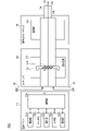
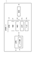
- FIG. 1 is a block diagram schematically showing a configuration example of an information processing system according to the first embodiment of the present invention.
- FIG. 2 is a schematic diagram schematically showing a first configuration example of the suction device according to the first embodiment of the present invention.
- FIG. 3 is a schematic diagram schematically showing a second configuration example of the suction device according to the first embodiment of the present invention.
- FIG. 4 is a block diagram schematically showing a configuration example of an information processing server according to the first embodiment of the present invention.
- FIG. 5 is a flowchart showing a processing example by the information processing server according to the first embodiment of the present invention.
- FIG. 6 is a block diagram schematically showing a configuration example of an information processing server according to a second embodiment of the present invention.
- FIG. 1 is a block diagram schematically showing a configuration example of an information processing system according to the first embodiment of the present invention.
- FIG. 2 is a schematic diagram schematically showing a first configuration example of the suction device according to the first embodiment of the
- FIG. 7 is a block diagram schematically showing a configuration example of a user terminal according to a second embodiment of the present invention.
- FIG. 8 is a flowchart showing a processing example by the information processing server according to the second embodiment of the present invention.
- FIG. 9 is a flowchart showing a processing example by the user terminal according to the second embodiment of the present invention.
- FIG. 1 is a schematic configuration diagram of an information processing system according to the first embodiment of the present invention.
- the information processing system 10 is exemplified by n units (n is an arbitrary integer value of 1 or more) of suction devices 1a to 1n and n units of suction devices 1a to 1n, respectively. It includes n user terminals (n is an arbitrary integer value of 1 or more) to be connected, and an information processing server 3 configured to be able to communicate with the user terminals 2a to 2n via a network N. It is composed.
- n suction devices are described without distinction, the reference numerals are partially omitted and the term "suction device 1" is simply referred to.
- n user terminals when the n user terminals are described without distinction, the reference numerals are partially omitted and the term “user terminals 2” is simply referred to.
- Those having the same alphabetic code attached to the end of each of the suction device 1 and the user terminal 2 are assumed to be possessed by the same user.
- the suction device 1a and the user terminal 2a are possessed by the same user.
- the information processing system 10 is a so-called client / server system.
- the information processing system 10 is realized by the n user terminals 2 which are clients and the information processing server 3 communicating with each other via the network N.
- the network N is realized by, for example, a network such as the Internet or a mobile phone network, a LAN (Local Area Network), or a network combining these.
- the suction device 1 is an electronic device that produces a substance that is sucked by the user.
- the suction device 1 corresponds to a suction tool or a flavor suction tool.
- a configuration example of the suction device that can be the suction device 1 will be described later.
- the user terminal 2 is a portable electronic device having a communication function.
- the user terminal 2 is a smartphone, a tablet terminal, or the like.
- the information processing server 3 is a computer having an information processing function.
- the information processing server 3 is realized by, for example, one or a plurality (at least one) of server devices. A configuration example of the information processing server 3 will be described later.
- the information processing server 3 is an example of an information processing device.
- the suction device 1 and the user terminal 2 are related to each other, and data can be transmitted and received by both parties by executing short-range wireless communication such as Bluetooth (registered trademark) or BLE (Bluetooth Low Energy) communication. It becomes.
- the transmission and reception of data between the suction device 1 and the user terminal 2 is not limited to BLE communication, and for example, Wi-Fi (registered trademark), LPWAN (Low Power Wide Area Network), NFC (Near Field Communication), etc. It may be executed by any communication.
- the transmission / reception of data between the suction device 1 and the user terminal 2 is not necessarily limited to wireless communication, and may be wired communication such as USB (Universal Serial Bus), Mini USB, Micro USB, and Lightning.
- the suction device is a device that produces a substance that is sucked by the user.
- the substance produced by the suction device will be described as being an aerosol.
- the substance produced by the suction device may be a gas.
- FIG. 2 is a schematic diagram schematically showing a first configuration example of a suction device.
- the suction device 100A includes a power supply unit 110, a cartridge 120, and a flavoring cartridge 130.
- the power supply unit 110 includes a power supply unit 111A, a sensor unit 112A, a notification unit 113A, a storage unit 114A, a communication unit 115A, and a control unit 116A.
- the cartridge 120 includes a heating unit 121A, a liquid guiding unit 122, and a liquid storage unit 123.
- the flavoring cartridge 130 includes a flavor source 131 and a mouthpiece 124.
- An air flow path 180 is formed in the cartridge 120 and the flavoring cartridge 130.
- the power supply unit 111A stores electric power. Then, the power supply unit 111A supplies electric power to each component of the suction device 100A based on the control by the control unit 116A.
- the power supply unit 111A may be composed of, for example, a rechargeable battery such as a lithium ion secondary battery.
- the sensor unit 112A acquires various information about the suction device 100A.
- the sensor unit 112A is composed of a pressure sensor such as a microphone capacitor, a flow rate sensor, a temperature sensor, or the like, and acquires a value associated with suction by the user.
- the sensor unit 112A is configured by an input device such as a button or a switch that receives input of information from the user.
- the notification unit 113A notifies the user of the information.
- the notification unit 113A is composed of, for example, a light emitting device that emits light, a display device that displays an image, a sound output device that outputs sound, a vibrating vibration device, and the like.
- the storage unit 114A stores various information for the operation of the suction device 100A.
- the storage unit 114A is composed of a non-volatile storage medium such as a flash memory.
- the storage unit 114A may store the registration code. Further, the storage unit 114A may store the device ID. The registration code and device ID will be described later.
- the communication unit 115A is a communication interface capable of performing communication conforming to any wired or wireless communication standard.
- a communication standard for example, Wi-Fi (registered trademark), Bluetooth (registered trademark), or the like can be adopted.
- the control unit 116A functions as an arithmetic processing device and a control device, and controls the overall operation in the suction device 100A according to various programs.
- the control unit 116A is realized by, for example, an electronic circuit such as a CPU (Central Processing Unit) and a microprocessor.
- the liquid storage unit 123 stores the aerosol source.
- the atomization of the aerosol source produces an aerosol.
- Aerosol sources are, for example, polyhydric alcohols such as glycerin and propylene glycol, and liquids such as water. Aerosol sources may contain tobacco-derived or non-tobacco-derived flavor components.
- the suction device 100A is a medical inhaler such as a nebulizer
- the aerosol source may include a drug.
- the liquid guiding unit 122 guides and holds the aerosol source, which is the liquid stored in the liquid storage unit 123, from the liquid storage unit 123.
- the liquid guiding portion 122 is a wick formed by twisting a fiber material such as glass fiber or a porous material such as a porous ceramic. In that case, the aerosol source stored in the liquid storage unit 123 is induced by the capillary effect of the wick.
- the heating unit 121A heats the aerosol source to atomize the aerosol source and generate an aerosol.
- the heating unit 121A is configured as a coil and is wound around the liquid induction unit 122.
- the heating unit 121A generates heat, the aerosol source held in the liquid induction unit 122 is heated and atomized to generate an aerosol.
- the heating unit 121A generates heat when power is supplied from the power supply unit 111A.
- power may be supplied when the sensor unit 112A detects that the user has started suction and / or that predetermined information has been input. Then, when it is detected by the sensor unit 112A that the user has finished the suction and / or that the predetermined information has been input, the power supply may be stopped.
- the flavor source 131 is a component for imparting a flavor component to the aerosol.
- the flavor source 131 may contain a tobacco-derived or non-tobacco-derived flavor component.
- the air flow path 180 is a flow path of air sucked by the user.
- the air flow path 180 has a tubular structure having an air inflow hole 181 which is an inlet of air into the air flow path 180 and an air outflow hole 182 which is an outlet of air from the air flow path 180 at both ends.
- the liquid guiding portion 122 is arranged on the upstream side (the side close to the air inflow hole 181), and the flavor source 131 is arranged on the downstream side (the side close to the air outflow hole 182).
- the air flowing in from the air inflow hole 181 due to the suction by the user is mixed with the aerosol generated by the heating unit 121A, and is transported to the air outflow hole 182 through the flavor source 131 as shown by the arrow 190.
- the flavor component contained in the flavor source 131 is imparted to the aerosol.
- the mouthpiece 124 is a member that can be held by the user during suction.
- An air outflow hole 182 is arranged in the mouthpiece 124. The user can take in the mixed fluid of aerosol and air into the oral cavity by holding and sucking the mouthpiece 124.
- suction device 100A has been described above.
- the configuration of the suction device 100A is not limited to the above, and various configurations exemplified below can be adopted.
- the suction device 100A does not have to include the flavoring cartridge 130.
- the cartridge 120 is provided with the mouthpiece 124.
- the suction device 100A may include a plurality of types of aerosol sources.
- a plurality of types of aerosols generated from a plurality of types of aerosol sources may be mixed in the air flow path 180 to cause a chemical reaction, whereby another type of aerosol may be produced.
- the means for atomizing the aerosol source is not limited to heating by the heating unit 121A.
- the means for atomizing the aerosol source may be oscillating atomization or induction heating.
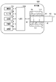
- FIG. 3 is a schematic diagram schematically showing a second configuration example of the suction device.
- the suction device 100B includes a power supply unit 111B, a sensor unit 112B, a notification unit 113B, a storage unit 114B, a communication unit 115B, a control unit 116B, a heating unit 121B, a holding unit 140, and a holding unit 140. Includes insulation 144.
- Each of the power supply unit 111B, the sensor unit 112B, the notification unit 113B, the storage unit 114B, the communication unit 115B, and the control unit 116B is substantially the same as the corresponding components included in the suction device 100A according to the first configuration example. Is.
- the power supply unit 111A and the power supply unit 111B are described as the power supply unit 111 when the two are described without distinction.
- the sensor unit 112A and the sensor unit 112B are the sensor unit 112
- the notification unit 113A and the notification unit 113B are the notification unit 113
- the storage unit 114A and the storage unit 114B are the storage unit 114
- the communication unit 115A and the communication unit 115B are.
- the communication unit 115, the control unit 116A and the control unit 116B are described as the control unit 116
- the heating unit 121A and the heating unit 121B are described as the heating unit 121.
- the holding portion 140 has an internal space 141, and holds the stick-type base material 150 while accommodating a part of the stick-type base material 150 in the internal space 141.
- the holding portion 140 has an opening 142 that communicates the internal space 141 to the outside, and holds the stick-type base material 150 inserted into the internal space 141 from the opening 142.
- the holding portion 140 is a tubular body having an opening 142 and a bottom portion 143 as a bottom surface, and defines a columnar internal space 141.
- the holding portion 140 also has a function of defining a flow path of air supplied to the stick-type base material 150.
- An air inflow hole which is an inlet for air to such a flow path, is arranged, for example, at the bottom 143.
- the air outflow hole which is an outlet for air from such a flow path, is an opening 142.
- the stick-type base material 150 includes a base material portion 151 and a mouthpiece portion 152.
- the base material portion 151 contains an aerosol source.
- the aerosol source is not limited to a liquid, but may be a solid.
- the heating unit 121B has the same configuration as the heating unit 121A according to the first configuration example. However, in the example shown in FIG. 3, the heating unit 121B is formed in a film shape and is arranged so as to cover the outer periphery of the holding unit 140. Then, when the heating unit 121B generates heat, the base material portion 151 of the stick-type base material 150 is heated from the outer periphery to generate an aerosol.
- the heat insulating portion 144 prevents heat transfer from the heating portion 121B to other components.
- the heat insulating portion 144 is made of a vacuum heat insulating material, an airgel heat insulating material, or the like.
- suction device 100B has been described above.
- the configuration of the suction device 100B is not limited to the above, and various configurations exemplified below can be adopted.
- the heating portion 121B may be configured in a blade shape and may be arranged so as to project from the bottom portion 143 of the holding portion 140 to the internal space 141. In that case, the blade-shaped heating portion 121B is inserted into the base material portion 151 of the stick-type base material 150, and the base material portion 151 of the stick-type base material 150 is heated from the inside. As another example, the heating portion 121B may be arranged so as to cover the bottom portion 143 of the holding portion 140. Further, the heating unit 121B is a combination of two or more of a first heating unit that covers the outer periphery of the holding unit 140, a blade-shaped second heating unit, and a third heating unit that covers the bottom portion 143 of the holding unit 140. It may be configured as.
- the holding portion 140 may include an opening / closing mechanism such as a hinge that opens / closes a part of the outer shell forming the internal space 141. Then, the holding portion 140 may sandwich the stick-type base material 150 inserted in the internal space 141 by opening and closing the outer shell.
- the heating unit 121B may be provided at the holding portion of the holding unit 140 and may be heated while pressing the stick-type base material 150.
- the means for atomizing the aerosol source is not limited to heating by the heating unit 121B.
- the means for atomizing the aerosol source may be induction heating.
- the suction device 100B may further include a heating unit 121A, a liquid induction unit 122, a liquid storage unit 123, and an air flow path 180 according to the first configuration example, and the air flow path 180 air outflow hole 182. May also serve as an air inflow hole to the internal space 141.
- the mixed fluid of the aerosol and air generated by the heating unit 121A flows into the internal space 141, is further mixed with the aerosol generated by the heating unit 121B, and reaches the user's oral cavity.
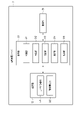
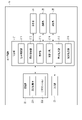
- FIG. 4 is a block diagram schematically showing a configuration example of an information processing server according to the first embodiment of the present invention.
- the information processing server 3 includes a control unit 31, a storage unit 32, and a communication unit 33. The parts are connected to each other via a bus line.
- the control unit 31 controls the operation of the entire information processing server 3 according to the program stored in the storage unit 32.
- the control unit 31 is composed of an electronic circuit such as a processor.
- the processor is a CPU or the like.
- the control unit 31 realizes each unit described later by executing the program stored in the storage unit 32, and executes various operations.
- the storage unit 32 is composed of a main storage device and an auxiliary storage device.
- the main storage consists of volatile memory that provides a working area for the processor.
- the main storage device is composed of a RAM (Random Access Memory) or the like.
- the auxiliary storage device is composed of a non-volatile memory that stores various information and programs for the operation of the information processing server 3.
- the auxiliary storage device is composed of an HDD (Hard Disk Drive), an SSD (Solid State Drive), or the like.
- the storage unit 32 stores in the control unit 31 a program for realizing each unit described later.
- the storage unit 32 stores the user information DB 321 and the setting information DB 322.
- the user information DB 321 is a database that stores user information that is information unique to the user who owns the user terminal 2.
- the user information DB 321 includes a user information record composed of at least one of a registration code, a user ID, a device ID, user data, and a registration flag.
- the user ID is an identifier uniquely assigned to the user.
- the user ID is an example of user identification information.
- the user ID is used for user registration by the information processing server 3.
- the user ID is input by the user from an input unit (not shown) of the user terminal 2 and is set at the time of user registration.
- the user ID is transmitted from the user terminal 2 to the information processing server 3 at the time of user registration, and is stored in the user information DB 321.
- the registration code is information used for registering the suction device 1 in the information processing server 3.
- the registration code is composed of, for example, a combination of a predetermined number of alphanumerical characters, and is provided for each suction device 1.
- the registration code is transmitted from the suction device 1 to the information processing server 3 via the user terminal 2 and stored in the user information DB 321.
- the device ID is the device ID of the suction device 1 associated with the user terminal 2.
- the device ID of the suction device 1 is identification information for identifying each suction device 1.
- the device ID is, for example, a serial number.
- the device ID is an example of the identification information of the suction device 1.
- the device ID is transmitted from the user terminal 2 to the information processing server 3 and stored in the user information DB 321.
- User data is data that identifies the user.
- the user data is used for user registration by the information processing server 3.
- the user data includes at least one of information indicating a user name, a user's gender, age, identity verification information, and the like.
- the identity verification information is, for example, an image of a public identification card such as a driver's license or my number card, or an electronic certificate for identity verification read from a my number card or the like.
- the identity verification information may be, for example, any information that can confirm the age of the user.
- User data is input from an input unit (not shown) of the user terminal 2 at the time of user registration or subsequent update of user registration by the user.
- the user data is transmitted from the user terminal 2 to the information processing server 3 and stored in the user information DB 321.
- the registration flag is information indicating that the user registration is completed in the information processing server 3. Adding the registration flag is to make the user available to various services provided by the information processing server 3.
- User registration is, for example, account registration for authenticating a user.
- the user information may be updated as appropriate.
- the user information may include information other than the above.
- the setting information DB 322 is a database that records information for setting a plurality of types of suction devices 1.
- the information for setting the suction device 1 is also hereinafter referred to as "setting information".
- the setting information is information that differs depending on the type of the suction device 1.
- the setting information is guide information indicating a procedure for setting the suction device 1 performed by the user when the suction device 1 is used for the first time.
- the setting information DB 322 stores the setting information in association with the type information of the suction device 1.
- the type information is information such as the model number and version information of the suction device 1.
- the type information of the suction device 1 may be a part of the device ID of the suction device 1, or may be information associated with the registration code of the suction device 1 or the device ID by a database (not shown).
- the data of the setting information DB 322 may be stored in the storage unit 32 in advance, or may be downloaded from a server (not shown) to the information processing server 3 via the network N.
- the setting information DB 322 may be updated as appropriate.
- the communication unit 33 is composed of one or more communication interfaces capable of performing communication conforming to any wireless communication standard.
- the communication unit 33 includes one or more communication interfaces capable of communicating between the information processing server 3 and the user terminal 2 via the network N as described above.
- the hardware configuration of the information processing server 3 is not limited to the above configuration.
- the information processing server 3 makes it possible to omit or change the above-mentioned components and add new components as appropriate.
- control unit 31 realizes an acquisition unit 311, a specific unit 312, a determination unit 313, an execution unit 314, and an output unit 315. It should be noted that each unit realized by the control unit 31 can also be said to be each function. The fact that each part is realized in the control unit 31 can also mean that each part is realized in the processor.
- the acquisition unit 311 acquires the registration code from the user terminal 2 connected to the suction device 1 in response to the activation of the suction device 1, for example, via the communication unit 33. Further, the acquisition unit 311 may acquire the device ID of the suction device 1 from the user terminal 2 connected to the suction device 1 in response to the activation of the suction device 1 via the communication unit 33. Further, the acquisition unit 311 acquires information used for user registration from the user terminal 2 via the communication unit 33. The information used for user registration is also hereinafter referred to as "user registration information".
- the user registration information includes a user ID. At the time of user registration or update of user registration, the user registration information includes user data in addition to the user ID. If the user has completed the user registration in the past and does not update the user registration, the user registration information may not include the user data.
- the user registration is to register the user registration information of the user who uses the suction device 1 in the information processing server 3.
- the user registration may be the registration of the suction device 1, that is, the registration of the suction device 1 (so-called device registration). Further, the user registration may be to register a user who uses the suction device 1.
- the user registration may be completed when either the registration of the suction device 1 (so-called device registration) or the user registration is completed. Further, the user registration may be completed when both the registration of the suction device 1 (so-called device registration) and the user registration are completed.
- the user registration information includes at least one of a registration code, a device ID, and a user ID.
- the user registration information may include only one of a registration code, a device ID, and a user ID.
- the user registration information may include a plurality of information among the registration code, the device ID, and the user ID.
- the identification unit 312 specifies the setting information corresponding to the registration code or device ID acquired by the acquisition unit 311.
- the determination unit 313 determines whether or not the user registration of the user is completed based on the user registration information acquired by the acquisition unit 311. The determination unit 313 determines whether or not the registration of the suction device 1 (so-called device registration) has been completed based on the registration code or the device ID in the user registration information acquired by the acquisition unit 311. Further, the determination unit 313 may determine whether or not the user registration is completed based on the user ID included in the user registration information acquired by the acquisition unit 311. The determination unit 313 may determine whether or not both the registration of the suction device 1 (so-called device registration) and the registration of the user have been completed.
- the execution unit 314 executes the user registration of the user based on the user registration information acquired by the acquisition unit 311 in response to the determination by the determination unit 313 that the user registration of the user has not been completed.
- the output unit 315 outputs the setting information specified by the specific unit 312 to the user terminal 2 via the communication unit 33.
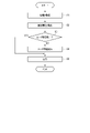
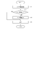
- FIG. 5 is a flowchart showing a processing example by the information processing server according to the first embodiment of the present invention.
- the processing procedure described below is only an example, and each processing may be changed as much as possible. Further, with respect to the processing procedure described below, steps can be omitted, replaced, and added as appropriate according to the embodiment.
- the user A, the suction device 1a, and the user terminal 2a will be described below as an example.
- User A is a user who possesses the suction device 1a and the user terminal 2a.
- the acquisition unit 311 acquires the registration code or device ID of the suction device 1a from the user terminal 2a connected to the suction device 1a in response to the activation of the suction device 1a (step S1).
- step S1 for example, the acquisition unit 311 acquires the user registration information of the user A from the user terminal 2a together with the registration code or the device ID of the suction device 1a via the communication unit 33.
- the suction device 1a transmits the registration code or device ID of the suction device 1a to the user terminal 2a in response to the activation such as the initial activation.
- the user terminal 2a becomes able to communicate with the suction device 1a in response to the activation of the suction device 1a, and receives the registration code or device ID of the suction device 1a transmitted from the suction device 1a.
- the user terminal 2a responds to the reception of the registration code or device ID of the suction device 1a from the suction device 1a, and the user registration information of the user A together with the registration code or device ID of the suction device 1a via the network N. Is transmitted to the information processing server 3.
- the user registration information is information input by the user A from an input unit (not shown) of the user terminal 2a.
- the user registration information includes a user ID.
- the user registration information may include user data in addition to the user ID.
- the acquisition unit 311 may acquire both the registration code of the suction device 1a and the device ID.
- the acquisition unit 311 adds the acquired registration code or device ID to the user information DB 321 one by one in association with the user ID that already exists in the user information DB 321.
- the acquisition unit 311 adds the user data associated with the user ID to the user information DB 321 so as to update the user data.
- the user registration may be updated.
- the registration flag is added in association with the user ID of the user A in the user information DB 321.
- the acquisition unit 311 adds a user information record associated with the acquired registration code or device ID and the user ID and user data included in the acquired user registration information to the user information DB 321. Since the user registration of the user A has not been completed, the registration flag is not added in association with the user ID of the user A in the user information DB 321.
- the identification unit 312 specifies the setting information corresponding to the registration code or device ID acquired by the acquisition unit 311 (step S2).
- step S2 for example, the specific unit 312 acquires the registration code or device ID of the suction device 1a acquired by the acquisition unit 311 from the user information DB 321.
- the specific unit 312 acquires the type information of the suction device 1a based on a part of the registration code or the device ID of the suction device 1a or a database (not shown).
- the specifying unit 312 specifies the setting information associated with the type information of the suction device 1a based on the setting information DB 322.
- the determination unit 313 determines whether or not the user registration of the user A is completed based on the user registration information (step S3).
- the determination unit 313 acquires the user ID acquired by the acquisition unit 311 from the user information DB 321.
- the determination unit 313 determines whether or not the user registration is completed based on the registration flag associated with the user ID.
- the determination unit 313 may collate the user ID with a database (not shown) that manages the information of the registered user to determine whether or not the user registration is completed.
- "completion" of user registration includes a state in which user registration has already been performed, that is, a state in which user registration has been completed.
- step S3 determines that the user registration of the user A has been completed (step S3: YES)
- step S5 determines that the user registration of the user A has not been completed
- step S3 determines that the user registration of the user A has not been completed
- the execution unit 314 executes the user registration of the user A based on the user registration information in response to the determination by the determination unit 313 that the user registration of the user A has not been completed (step S4).
- step S4 for example, the execution unit 314 acquires the user data included in the user registration information acquired by the acquisition unit 311 from the user information DB 321.
- the execution unit 314 executes the user registration of the user A based on the user data.
- the execution unit 314 adds a registration flag in the user information DB 321 in association with the user ID of the user A.
- the execution of user registration by the execution unit 314 corresponds to the state in which the user has already been registered. According to this example, the information processing server 3 can execute user registration without newly acquiring user registration information from user A.
- the execution unit 314 executes the user registration of the user A based on the identity verification information of the user A.
- the execution unit 314 executes the user registration of the user A.
- the execution unit 314 does not execute the user registration of the user A.
- the information processing server 3 can confirm the age of the user A when executing the user registration. Therefore, the information processing server 3 can encourage the use of the suction device 1a in accordance with the age regulation.
- the output unit 315 outputs the setting information specified by the specific unit 312 to the user terminal 2a (step S5).
- step S5 for example, the output unit 315 outputs the setting information about the suction device 1a specified by the specific unit 312 to the user terminal 2a via the communication unit 33.
- "outputting" by the output unit 315 includes “transmitting" data.
- the output unit 315 outputs the setting information to the user terminal 2a according to the user registration state of the user A based on the user registration information.
- the user registration status is a user registration status.
- the output unit 315 outputs the setting information of the suction device 1a to the user terminal 2a in response to the determination by the determination unit 313 that the user registration of the user A is completed.
- the fact that the determination unit 313 determines that the user registration of the user A has been completed corresponds to the user-registered state of the user A.
- the output unit 315 outputs the setting information of the suction device 1a to the user terminal 2a in response to the user registration of the user A being executed by the execution unit 314.
- the fact that the user registration of the user A is executed by the execution unit 314 corresponds to the user-registered state of the user A.
- the information processing server 3 can present the setting information only to the user who has completed the user registration. Therefore, the information processing server 3 can suppress the use of a user whose user registration has not been completed.
- steps S3 to S4 may be omitted. That is, in step S1, the acquisition unit 311 acquires the registration code or device ID of the suction device 1a from the user terminal 2a via the communication unit 33, but does not have to acquire the user registration information. The information processing server 3 does not determine the completion of user registration and execute user registration.
- the output unit 315 may output the setting information specified by the specific unit 312 to the user terminal 2a in response to the acquisition of the identification information of the suction device 1a by the acquisition unit 311.
- the information processing server 3 indicates to the user terminal 2 that the user registration cannot be completed when the user registration is not completed for a predetermined reason in the user registration execution in step S4. May be output.
- the output unit 315 outputs the error information
- the output unit 315 does not output the setting information.
- the predetermined reason is, for example, that the user data does not include the identity verification information. Further, the predetermined reason is that, for example, the age of the user of the identity verification information included in the user data has not reached the predetermined age. Further, for example, the acquired registration code or device ID is already used for user registration of another user.
- the predetermined reason is not limited to these examples, and may be any reason as long as the user registration cannot be executed.
- the error signal may include information about a given reason.
- the user terminal 2a can acquire the setting information corresponding to the suction device 1a used by the user A from the outside. Therefore, even if the setting information is not stored in advance in the suction device 1a or the user terminal 2a, the information processing server 3 can present the setting information to the user A. In addition, the memory resources of the suction device 1a or the user terminal 2a can be saved. Further, the information processing server 3 can present the setting information corresponding to the suction device 1a necessary for the user A at a necessary timing without requiring the user A to search for the setting information.
- the information processing device may be realized by one device as described by taking the information processing server 3 as an example, or may be realized by a plurality of devices having distributed functions.
- the second embodiment will be described with reference to the drawings.
- the setting information is displayed on the user terminal based on the identification information of the suction device.
- the user terminal is an example of an information processing terminal.
- the same reference numerals are given to the same configurations as those of the first embodiment, and the description thereof will be omitted.
- the second embodiment mainly the parts different from the first embodiment will be described.
- FIG. 6 is a block diagram schematically showing a configuration example of an information processing server according to a second embodiment of the present invention.
- the storage unit 32 stores in the control unit 31 a program for realizing each unit described later.
- the storage unit 32 stores the user information DB 321. Unlike the first embodiment, the storage unit 32 does not store the setting information DB 322.
- the hardware configuration of the information processing server 3 is not limited to the above configuration.
- the information processing server 3 makes it possible to omit or change the above-mentioned components and add new components as appropriate.
- control unit 31 realizes an acquisition unit 311, a determination unit 313, an execution unit 314, and an output unit 315. Unlike the first embodiment, the control unit 31 does not have the specific unit 312. It should be noted that each unit realized by the control unit 31 can also be said to be each function. The fact that each part is realized in the control unit 31 can also mean that each part is realized in the processor.
- the acquisition unit 311 acquires the user registration information of the user from the user terminal 2 via the communication unit 33.
- the determination unit 313 determines whether or not the user registration of the user is completed based on the user registration information acquired by the acquisition unit 311. The determination unit 313 determines whether or not the registration of the suction device 1 (so-called device registration) has been completed based on the registration code or the device ID in the user registration information acquired by the acquisition unit 311. Further, the determination unit 313 may determine whether or not the user registration is completed based on the user ID included in the user registration information acquired by the acquisition unit 311. The determination unit 313 may determine whether or not both the registration of the suction device 1 (so-called device registration) and the registration of the user have been completed.
- the execution unit 314 executes the user registration of the user based on the user registration information in response to the determination by the determination unit 313 that the user registration of the user has not been completed.
- the output unit 315 outputs a notification to the user terminal 2 via the communication unit 33.
- the notification is a notification regarding the completion of user registration of the user.
- the notification indicates that the user has already registered as a user. Registered as a user corresponds to the fact that the user registration of the user has been completed or that the user registration of the user has been executed.
- FIG. 7 is a block diagram schematically showing a configuration example of a user terminal according to a second embodiment of the present invention.
- the user terminal 2a includes a control unit 21, a storage unit 22, an input unit 23, a display unit 24, a communication unit 25, and a detection unit 26.
- the parts are connected to each other via a bus line.
- the control unit 21 controls the operation of the entire user terminal 2a according to the program stored in the storage unit 22.
- the control unit 21 is composed of an electronic circuit such as a processor.
- the processor is a CPU or the like.
- the storage unit 22 is composed of a main storage device and an auxiliary storage device, similarly to the storage unit 32 described above.
- the storage unit 22 stores in the control unit 21 a program for realizing each unit described later.
- the storage unit 22 stores the setting information DB 221 and the application 222.
- the setting information DB 221 is a database that stores the setting information of the suction device 1 like the setting information DB 322 described above.
- the data of the setting information DB 221 may be downloaded from the information processing server 3 via the network N, or may be downloaded from a server (not shown) via the network N to the user terminal 2a.
- the setting information DB 322 may be updated as appropriate.
- the data of the setting information DB 322 may be downloaded in association with the download of the application 222.
- the application 222 is an application program that provides various functions to the user terminal 2a.
- the application 222 may be downloaded from the information processing server 3 via the network N, or may be downloaded from a server (not shown) via the network N to the user terminal 2a.
- Application 222 may be updated as appropriate.
- the application 222 provides a function of displaying the setting information stored in the setting information DB 221 on the display unit 24.
- the application 222 displays the setting information of a plurality of types of suction devices 1 on the display unit 24.
- the application 222 provides a function for enabling the display of the setting information stored in the setting information DB 221.
- the input unit 23 accepts instructions or captures data based on the operation by the user.
- the input unit 23 is composed of a keyboard, a touch pad, a camera, or the like.
- the display unit 24 displays various screens.
- the display unit 24 is composed of a liquid crystal display or the like.
- the communication unit 25 is composed of one or more communication interfaces capable of performing communication conforming to any wired or wireless communication standard.
- the communication unit 25 includes one or more communication interfaces capable of communicating between the user terminal 2a and the suction device 1a as described above.
- the communication unit 25 includes one or more communication interfaces capable of communicating between the user terminal 2a and the information processing server 3 via the network N as described above.
- the detection unit 26 is composed of sensors that detect various types of information.
- the detection unit 26 includes a sensor that detects the position information of the user terminal 2a.
- the position information is information indicating latitude and longitude.
- the sensor that detects the position information is a GPS sensor.
- the hardware configuration of the user terminal 2a is not limited to the above configuration.
- the user terminal 2a makes it possible to omit or change the above-mentioned components and add new components as appropriate.
- a configuration example of the user terminal 2a has been described, but since the configuration of the user terminal 2 other than the user terminal 2a is the same as the configuration of the user terminal 2a, the description thereof will be omitted.
- control unit 21 realizes a first acquisition unit 211, a second acquisition unit 212, a specific unit 213, an activation unit 214, a first output unit 215, and a second output unit 216. It should be noted that each unit realized by the control unit 21 can also be said to be each function. The fact that each part is realized in the control unit 21 can also mean that each part is realized in the processor.
- the first acquisition unit 211 acquires the registration code or device ID of the suction device 1 from the suction device 1 in response to the activation of the suction device 1 via the communication unit 25.
- the first acquisition unit 211 may acquire both the registration code and the device ID of the suction device 1 from the suction device 1.
- the second acquisition unit 212 acquires the notification from the information processing server 3 via the communication unit 25.
- the identification unit 213 specifies the setting information corresponding to the registration code or the device ID in response to the acquisition of the notification by the second acquisition unit 212.
- the activation unit 214 enables the display of the setting information specified by the specific unit 213 based on the notification acquired by the second acquisition unit 212.
- the first output unit 215 outputs the user registration information to the information processing server 3 via the communication unit 25 in response to the acquisition of the registration code or the device ID by the first acquisition unit 211.
- the second output unit 216 outputs the setting information specified by the specific unit 213 to the display unit 24.
- the display unit 24 displays the setting information specified by the specific unit 213.
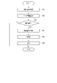
- FIG. 8 is a flowchart showing a processing example by the information processing server according to the second embodiment of the present invention.
- the processing procedure described below is only an example, and each processing may be changed as much as possible. Further, with respect to the processing procedure described below, steps can be omitted, replaced, and added as appropriate according to the embodiment.
- the user A, the suction device 1a, and the user terminal 2a will be described below as an example.
- User A is a user who possesses the suction device 1a and the user terminal 2a.
- the acquisition unit 311 acquires the user registration information of the user A (step S11).
- step S11 for example, the acquisition unit 311 acquires the user registration information of the user A from the user terminal 2a via the communication unit 33.
- the user registration information of the user A is transmitted from the user terminal 2a connected to the suction device 1a to the information processing server 3 in response to the activation of the suction device 1a.
- the user registration information includes a user ID.
- the user registration information includes user data in addition to the user ID.
- the acquisition unit 311 adds the acquired user registration information to the user information DB 321 as in the first embodiment.
- the determination unit 313 determines whether or not the user registration of the user A is completed based on the user registration information (step S12). In step S12, for example, the determination unit 313 determines whether or not the user registration of the user A has been completed, as in the first embodiment.
- step S12 determines that the user registration of the user A has been completed (step S12: YES)
- step S12 determines that the user registration of the user A has been completed (step S12: YES)
- step S12 determines that the user registration of the user A has not been completed (step S12: NO)
- step S12 determines that the user registration of the user A has not been completed (step S12: NO)
- the execution unit 314 executes the user registration of the user A in response to the determination by the determination unit 313 that the user registration of the user A has not been completed (step S13).
- step S13 for example, the execution unit 314 executes the user registration of the user A as in the first embodiment.
- the information processing server 3 can execute user registration without newly acquiring user registration information from user A.
- the execution unit 314 executes the user registration of the user A based on the identity verification information of the user A.
- the information processing server 3 can confirm the age of the user when executing the user registration. Therefore, the information processing server 3 can encourage the use of the suction device 1a in accordance with the age regulation.
- the output unit 315 outputs a notification to the user terminal 2a (step S14).
- step S14 for example, the output unit 315 outputs a notification regarding the completion of user registration of the user A to the user terminal 2a via the communication unit 33.
- the output unit 315 sends a notification to the user terminal 2a indicating that the user registration of the user A is completed in response to the determination by the determination unit 313 that the user registration of the user A is completed.
- the output unit 315 outputs a notification indicating that the user registration of the user A has been executed to the user terminal 2a in response to the execution of the user registration of the user A by the execution unit 314. Note that "outputting" to the user terminal 2a includes “transmitting" data to the user terminal 2a.
- the information processing server 3 outputs an error signal indicating that the user registration cannot be performed to the user terminal 2 when the user registration is not completed for a predetermined reason in the user registration execution. You may.
- the error signal may include information about a given reason.
- FIG. 9 is a flowchart showing a processing example by the user terminal according to the second embodiment of the present invention.
- the processing procedure described below is only an example, and each processing may be changed as much as possible. Further, with respect to the processing procedure described below, steps can be omitted, replaced, and added as appropriate according to the embodiment.
- the user A, the suction device 1a, and the user terminal 2a will be described below as an example.
- User A is a user who possesses the suction device 1a and the user terminal 2a.
- the first acquisition unit 211 acquires the registration code or device ID of the suction device 1a from the suction device 1a in response to the activation of the suction device 1a via the communication unit 25 (step S21).
- step S21 for example, the first acquisition unit 211 receives the registration code or device ID of the suction device 1a from the suction device 1a in response to the initial activation of the suction device 1a via the communication unit 25.
- the user terminal 2a becomes communicable with the suction device 1a in response to the activation of the suction device 1a, and receives the registration code or device ID of the suction device 1a transmitted from the suction device 1a.
- the first acquisition unit 211 stores the acquired registration code or device ID of the suction device 1a in the storage unit 22.
- the acquired registration code or device ID is stored in the storage unit 22 one by one.
- the first acquisition unit 211 may acquire both the registration code of the suction device 1a and the device ID from the suction device 1a in response to the activation of the suction device 1a.
- the first output unit 215 outputs the user registration information to the information processing server 3 via the communication unit 25 in response to the acquisition of the registration code or the device ID by the first acquisition unit 211 (step S22). .. In step S22, for example, the first output unit 215 outputs the user registration information input by the user A via the input unit 23 to the information processing server 3.
- the user registration information includes a user ID.
- the user registration information includes user data in addition to the user ID.
- the user registration information input via the input unit 23 is stored in the storage unit 22 one by one.
- the user registration information may be updated as appropriate by the input of the user A.
- the first output unit 215 acquires the user registration information from the storage unit 22 in response to the acquisition of the registration code or the device ID by the first acquisition unit 211.
- the first output unit 215 outputs the acquired user registration information to the information processing server 3.
- the second acquisition unit 212 acquires a notification regarding the completion of user registration of user A from the information processing server 3 via the communication unit 25 (step S23).
- step S23 for example, the second acquisition unit 212 acquires a notification regarding the completion of user registration of the user A based on the user registration information output by the first output unit 215. Since the notification regarding the completion of user registration of user A is a response to the user registration information output by the first output unit 215, it is a notification based on the user registration information.
- the second acquisition unit 212 acquires a notification from the information processing server 3 indicating that the user registration of the user A is completed.
- the second acquisition unit 212 acquires a notification from the information processing server 3 indicating that the user registration of the user A has been executed.
- step S23: YES When the second acquisition unit 212 acquires the notification (step S23: YES), the process transitions from step S23 to step S24. If the second acquisition unit 212 does not acquire the notification (step S23: NO), the process ends.
- the identification unit 213 specifies the setting information corresponding to the registration code or the device ID in response to the acquisition of the notification by the second acquisition unit 212 (step S24).
- the specific unit 213 acquires the registration code or device ID of the suction device 1a from the storage unit 22.
- the identification unit 312 specifies the type information of the suction device 1a based on the registration code or the device ID of the suction device 1a.
- the type information may be a part of the registration code or device ID of the suction device 1a, and is associated with the registration code or device ID of the suction device 1a by a database (not shown) stored in the storage unit 22. May be.
- the specifying unit 213 specifies the setting information associated with the type information of the suction device 1a based on the setting information DB 221.
- the activation unit 214 enables the display of the setting information specified by the specific unit 213 based on the notification acquired by the second acquisition unit 212 (step S25).
- step S25 for example, the activation unit 214 enables the display of only the setting information specified by the specific unit 213 among the setting information stored in the setting information DB 221.
- the activation unit 214 maintains the invalidity of the display of the setting information other than the setting information specified by the specific unit 213 among the setting information stored in the setting information DB 221.
- the second output unit 216 outputs the setting information specified by the specific unit 213 to the display unit 24 in response to the activation of the display of the setting information specified by the specific unit 213 by the activation unit 214 (step). S26).
- step S26 for example, the second output unit 216 outputs the setting information of the suction device 1a to the display unit 24.
- the display unit 24 displays the setting information of the suction device 1a.
- the display of the setting information of the suction device 1a is realized by, for example, the display function of the application 222.
- the user terminal 2a can acquire the setting information of the suction device 1a used by the user A from the outside. Therefore, even if the setting information is not stored in advance in the suction device 1a, the user terminal 2a can present the setting information to the user A. Moreover, the memory resource of the suction device 1a can be saved. Further, according to this example, the user terminal 2a can enable the display of the setting information only for the user who has completed the user registration. Therefore, the user terminal 2a can suppress the use of a user whose user registration has not been completed.
- step S25 may be omitted in the above processing by the user terminal 2a.
- the display of the setting information stored in the setting information DB 221 is valid regardless of whether or not the notification is acquired by the second acquisition unit 212.
- the second output unit 216 outputs the setting information specified by the specific unit 213 to the display unit 24 based on the notification acquired by the second acquisition unit 212.
- the user terminal 2 may acquire an error signal indicating that the user registration cannot be performed from the information processing server 3 when the user registration is not completed for a predetermined reason in the user registration execution. ..
- the error signal may include information about a given reason.
- the user terminal 2 acquires the error signal, the display of the setting information is not enabled and the setting information is not output to the display unit 24.
- the user terminal 2 may display a predetermined reason included in the acquired error signal on the display unit 24.
- the user terminal 2a can acquire the setting information of the suction device 1a used by the user A from the outside. Therefore, even if the setting information is not stored in advance in the suction device 1a, the user terminal 2a can present the setting information to the user A. Moreover, the memory resource of the suction device 1a can be saved. Further, according to this example, the user terminal 2a can present the setting information only to the user who has completed the user registration. Therefore, the user terminal 2a can suppress the use of a user whose user registration has not been completed. Further, the user terminal 2a can present the setting information corresponding to the suction device 1a necessary for the user A at a necessary timing without requiring the user A to search for the setting information.
- the information processing device may be realized by one device as described by taking the information processing server 3 as an example, or may be realized by a plurality of devices having distributed functions.
- the information processing terminal according to the second embodiment may be realized by one device as described by taking the user terminal 2 as an example, or may be realized by a plurality of devices having distributed functions.
- the program may be transferred in a state stored in the device, or may be transferred in a state not stored in the device. In the latter case, the program may be transferred via the network or may be transferred as recorded on a recording medium.
- the recording medium is a non-temporary tangible medium.
- the recording medium is a computer-readable medium.
- the recording medium may be any medium as long as it can store a program such as a CD-ROM or a memory card and can be read by a computer, and its form is not limited.
- the information processing server 3 outputs the setting information of the suction device 1 to the user terminal 2 of the user who has completed the user registration.
- the first modification is an embodiment in which the information processing server 3 outputs a control signal for enabling the suction device 1 of the user whose user registration has been completed, in addition to outputting the setting information. In the first modification, some or all the functions of the suction device 1 are restricted or invalidated until the user registration is completed.
- the user terminal 2 that has acquired the setting information may output a control signal for enabling the suction device 1 of the user whose user registration has been completed, instead of the information processing server 3.
- the determination unit 313 determines whether or not the user registration of the user is completed based on the user registration information acquired by the acquisition unit 311.
- the output unit 315 can output a control signal for controlling the suction device 1 via the communication unit 33 and the user terminal 2.
- the control signal for controlling the suction device 1 is, for example, a signal for enabling the operation of a part or all of the heating unit 121 of the suction device 1.
- control signal may be, for example, a signal for controlling the notification unit 113 of the suction device 1.
- the control signal is, for example, a signal for changing the color or pattern of light emission.
- the control signal is, for example, a signal for causing the color of the light emitting device to emit light in a predetermined color or a predetermined pattern when the user registration is completed.
- the control signal is, for example, a signal for causing the display device to display predetermined information.
- the control signal is, for example, a signal for displaying information indicating that the user registration is completed on the display device when the user registration is completed.
- the control signal is, for example, a signal for outputting a predetermined sound.
- the control signal is, for example, a signal for causing the sound output device to output a predetermined sound indicating that the user registration is completed when the user registration is completed.
- the control signal is a signal for changing the vibration pattern. The control signal is not limited to these examples.
- the control signal is, for example, a signal for causing the vibration device to output a predetermined vibration indicating that the user registration is completed when the user registration is completed.
- the output unit 315 outputs a notification regarding the completion of user registration to the user terminal 2a, and also outputs a control signal for controlling the suction device 1 via the user terminal 2. For example, when the determination unit 313 determines that the user registration has been completed, the output unit 315 outputs a control signal for controlling the suction device 1. Further, the output unit 315 outputs a control signal for controlling the suction device 1, for example, when the user registration is executed by the execution unit 314. The output unit 315 outputs, for example, a control signal for enabling the operation of a part or all of the heating unit 121 of the suction device 1.
- control unit 21 acquires a control signal for controlling the suction device 1 from the information processing server 3, the control unit 21 outputs a control signal to the suction device 1 via the communication unit 25.
- the control unit 21 outputs, for example, a control signal for enabling the operation of a part or all of the heating unit 121 of the suction device 1 to the suction device 1.
- the display unit 24 may display information indicating the content of control of the suction device 1 based on the control signal. For example, the display unit 24 has acquired a control signal for activating the operation of a part or all of the heating unit 121 of the suction device 1, and the display unit 24 has acquired a part or all of the heating unit 121 of the suction device 1. Information indicating that the operation has been activated may be displayed.
- the control unit 116 controls the operation of a part or all of the heating unit 121 based on the acquisition of the control signal for activating the operation of a part or all of the heating unit 121 of the suction device 1. For example, when all the functions of the heating unit 121 of the suction device 1 are disabled, the control unit 116 has acquired a control signal for enabling the operation of a part or all of the heating unit 121. Based on this, the operation of a part or all of the heating unit 121 is enabled.
- Enabling the operation of a part of the heating unit 121 is, for example, enabling the heating unit 121 to operate according to a part of the plurality of heating profiles when a plurality of heating profiles are stored in the storage unit 114. ..
- the control unit 116 makes the heating unit 121 operable according to some heating profiles based on the acquisition of a control signal indicating that the heating unit 121 can be operated according to some heating profiles.
- the heating profile is information that defines the operation of generating the aerosol (that is, the operation of heating the base material) performed by the suction device 1.
- the suction device 1 produces an aerosol by heating the substrate according to the heating profile.
- the heating profile is, for example, information indicating time-series changes in parameters related to the operation of generating an aerosol performed by the suction device 1.
- An example of the parameter is the temperature of the heating unit 121.
- the control unit 116 controls the temperature of the heating unit 121 so that the temperature similar to the target temperature is realized in the heating unit 121 with the temperature defined in the heating profile as the target temperature.
- the temperature control of the heating unit 121 can be realized by, for example, a known feedback control. Specifically, the control unit 116 supplies the electric power from the power supply unit 111 to the heating unit 121 in the form of a pulse by pulse width modulation (PWM) or pulse frequency modulation (PFM). In that case, the control unit 116 can control the temperature of the heating unit 121 by adjusting the duty ratio of the power pulse.
- PWM pulse width modulation
- PFM pulse frequency modulation
- the control unit 116 may control the electric power supplied to the heating unit 121, for example, the duty ratio described above, based on the difference between the temperature of the heating unit 121 and the target temperature.
- the feedback control may be, for example, PID control (Proportional-Integral-Differential Controller).
- the temperature of the heating unit 121 can be quantified, for example, by measuring or estimating the electric resistance value of the heat generating resistor constituting the heating unit 121. This is because the electric resistance value of the heat generation resistor changes according to the temperature.
- the electric resistance value of the heat-generating resistor can be estimated, for example, by measuring the amount of voltage drop in the heat-generating resistor.
- the amount of voltage drop in the heat-generating resistor can be measured by a voltage sensor that measures the potential difference applied to the heat-generating resistor.
- the temperature of the heating unit 121 can be measured by a temperature sensor installed near the heating unit 121.
- control unit 116 changes the color and pattern of the light emitted from the light emitting device based on the acquisition of the control signal for changing the color and pattern of the light emitted by the light emitting device which is the notification unit 113 of the suction device 1. ..
- the control unit 116 causes the light emitting device to emit light in a predetermined color or a predetermined pattern, for example, based on the acquisition of a control signal for emitting light in a predetermined color or a predetermined pattern indicating that the user registration is completed. ..
- control unit 116 causes the display device to display the predetermined information based on the acquisition of the control signal for displaying the predetermined information on the display device which is the notification unit 113 of the suction device 1.
- the control unit 116 causes the display device to display the information indicating that the user registration is completed, for example, based on the acquisition of the control signal for displaying the predetermined information indicating that the user registration is completed.
- control unit 116 causes the sound output device to output a predetermined sound based on the acquisition of a control signal for causing the sound output device, which is the notification unit 113 of the suction device 1, to output a predetermined sound.
- the control unit 116 causes the sound output device to output a sound indicating that the user registration is completed, for example, based on the acquisition of a control signal for outputting a predetermined sound indicating that the user registration is completed.
- control unit 116 changes the vibration pattern of the vibration device based on the acquisition of the control signal for changing the vibration pattern of the vibration device which is the notification unit 113 of the suction device 1.
- the control unit 116 vibrates the vibrating device with a predetermined vibration, for example, based on the acquisition of a control signal for vibrating with a predetermined vibration indicating that the user registration is completed.
- the suction device 1 can enable a part or all of the functions of the suction device 1 based on the control signal acquired from the information processing server 3 or the user terminal 2. For example, when the user registration is completed, the information processing server 3 or the user terminal 2 transmits a control signal for activating a part or all of the functions of the suction device 1 to the suction device 1, so that the user registration is performed. Upon completion, it becomes possible to activate some or all of the functions of the suction device 1.
- the second modification is an embodiment in which the user terminal 2 displays a notification prompting the user registration when the user terminal 2 receives the smoking information regarding the suction device 1 from the suction device 1 of the user who has not completed the user registration.
- the same reference numerals are given to the same configurations as those of the first embodiment, the second embodiment and the first modification, and the description thereof will be omitted.
- the second modification mainly the parts different from the first embodiment, the second embodiment, and the first embodiment will be described.
- the control unit 116 acquires various information about the suction device 1, the control unit 116 outputs the acquired various information to the user terminal 2 via the communication unit 115.
- the control unit 116 outputs, for example, a value associated with suction by the user acquired by a pressure sensor such as a microphone capacitor, a flow sensor or a sensor unit 112 such as a temperature sensor to the user terminal 2.
- the value associated with suction by the user is, for example, information on suction by the user, such as puff information indicating that the user has sucked, the number of puffs per smoking session, the puff time per smoking session, and the suction amount of one suction. If so, any information may be used.
- control unit 116 may output information indicating that the predetermined action has been executed to the user terminal 2 based on the user performing the predetermined action on the suction device 1.
- the predetermined action is, for example, that the user presses a button on the suction device 1 to initiate heating.
- the control unit 116 may output information about the heating unit 121 of the suction device 1 to the user terminal 2.
- the control unit 116 has, for example, information indicating that the preheating of the heating unit 121 has started, information indicating that the preheating of the heating unit 121 has been completed, and information indicating the elapsed time from the start of heating of the heating unit 121.
- Information indicating that the heating of the heating unit 121 has been completed may be output to the user terminal 2.
- control unit 116 acquires information on charging from the power supply unit 111 of the suction device 1
- the control unit 116 outputs the acquired information on charging to the user terminal 2 via the communication unit 115.
- the information regarding charging is, for example, the charging capacity of the power supply unit 111 and the deterioration information of the power supply unit 111.
- the suction device 1 may output information indicating that the power supply unit 111 is charged to the communication unit 115 when the power supply unit 111 is charged from an external power source.
- the control unit 116 acquires predetermined error information generated in the suction device 1 and failure information of each part of the suction device 1, the user terminal obtains the acquired error information and failure information via the communication unit 115. Output to 2.
- the predetermined error information may be, for example, a primary or permanent error generated in the power supply unit 111, the sensor unit 112, the control unit 116, or the heating unit 121.
- the failure information may be, for example, information to be acquired when the power supply unit 111, the sensor unit 112, the control unit 116, and the heating unit 121 become inoperable and need to be replaced.
- the permanent error information may be included in the failure information.
- control unit 21 acquires various information about the suction device 1 from the suction device 1, the control unit 21 inquires of the information processing server 3 whether or not the user registration is completed via the communication unit 115.
- the control unit 21 outputs at least one of the registration code, the device ID, and the user ID to the information processing server 3 via the communication unit 115, and inquires whether or not the user registration is completed.
- the control unit 21 may inquire of the information processing server 3 whether or not the registration of the suction device 1 (so-called device registration) has been completed via the communication unit 115. Further, the control unit 21 may inquire of the information processing server 3 whether or not the user registration is completed via the communication unit 115.
- control unit 21 When the control unit 21 has never acquired the information indicating that the user registration has been completed from the information processing server 3 in the past, the user registration is completed for the information processing server 3 via the communication unit 115. You may inquire whether or not you are doing so. If the control unit 21 has acquired information indicating that the user registration has been completed from the information processing server 3 in the past, the control unit 21 does not have to inquire whether or not the user registration has been completed.
- the control unit 21 may inquire of the information processing server 3 whether or not the user registration is completed via the communication unit 115.
- the predetermined information may be a part of information about the suction device 1 acquired from the suction device 1.
- the predetermined information is, for example, a value associated with suction by the user acquired by the sensor unit 112. Further, the predetermined information may be, for example, information indicating that the user has executed a predetermined action on the suction device 1. Further, the predetermined information may be information about the heating unit 121 of the suction device 1. Further, the predetermined information may be information regarding charging of the power supply unit 111 of the suction device 1. Further, the predetermined information may be predetermined error information generated in the suction device 1 or failure information of each part of the suction device 1.
- the trigger for inquiring whether the user registration is completed by the control unit 21 is when the predetermined information is acquired, and the inquiry is made by making the predetermined information a part of various information about the suction device 1. It is possible to adjust the frequency.
- the predetermined information is a value associated with suction by the user or information indicating that the user has executed a predetermined action on the suction device 1
- the control unit 21 registers the user each time the user uses the suction device 1. It is possible to inquire whether or not it has been completed, and it is possible to increase the frequency of inquiries.
- the predetermined information is information indicating that the power supply unit 111 is charged from an external power source
- the control unit 21 determines whether or not the user registration is completed each time the power supply unit 111 is charged by the external power source. It is possible to inquire about whether or not, and it is possible to reduce the frequency of inquiries.
- the control unit 21 When the control unit 21 acquires information indicating that the user registration has not been completed from the information processing server 3 as a result of the inquiry, the control unit 21 outputs information prompting the user to register the user. For example, when the control unit 21 acquires information indicating that the user registration has not been completed from the information processing server 3, the control unit 21 displays information prompting the user registration on the display unit 24. For example, in addition to the information prompting the user registration, the control unit 21 may display information on the function of the suction device 1 that becomes effective when the user registration is completed and the method for performing the user registration. The information on the method of user registration is, for example, information for registering identity verification information. Further, for example, in addition to the information prompting the user registration, the control unit 21 may display information indicating that the setting information of the suction device 1 can be displayed when the user registration is completed.
- the control unit 21 may display on the display unit 24 information indicating that only one of the registration of the suction device 1 (so-called device registration) or the registration of the user has not been completed. Further, the control unit 21 may display on the display unit 24 information indicating that both the registration of the suction device 1 (so-called device registration) and the registration of the user have not been completed.
- the acquisition unit 311 acquires an inquiry as to whether or not the user registration is completed from the user terminal 2 via the communication unit 33.
- the determination unit 313 determines whether or not the user registration of the user is completed based on the registration code, the device ID, and the user ID included in the inquiry. The determination unit 313 determines whether or not the registration of the suction device 1 (so-called device registration) has been completed based on the registration code or the device ID in the user registration information acquired by the acquisition unit 311. Further, the determination unit 313 may determine whether or not the user registration is completed based on the user ID included in the user registration information acquired by the acquisition unit 311. The determination unit 313 may determine whether or not both the registration of the suction device 1 (so-called device registration) and the registration of the user have been completed.
- the output unit 315 outputs information indicating that the user registration has not been completed to the user terminal 2.
- the information indicating that the user registration has not been completed may include information indicating that only one of the registration of the suction device 1 (so-called device registration) or the user registration has not been completed. Further, the information indicating that the user registration has not been completed may include information indicating that both the registration of the suction device 1 (so-called device registration) and the user registration have not been completed.
- the registration is completed in order to display a notification prompting the user registration. It is possible to prompt user registration when no suction device 1 is used, or when a user who has not completed registration is using the suction device 1. Further, in addition to prompting the user registration, the user terminal 2 presents the function of the suction device 1 that is activated when the user registration is completed, and thus presents the merit of the user registration to the user. It becomes possible.
- the present invention is not limited to the above embodiment, and can be variously modified at the implementation stage without departing from the gist thereof.
- each embodiment may be carried out in combination as appropriate, in which case the combined effect can be obtained.
- the above-described embodiment includes various inventions, and various inventions can be extracted by a combination selected from a plurality of disclosed constituent requirements. For example, even if some constituent elements are deleted from all the constituent elements shown in the embodiment, if the problem can be solved and the effect is obtained, the configuration in which the constituent elements are deleted can be extracted as an invention.
- 2nd acquisition unit 213 ... specific unit, 214 ... activation unit, 215 ... first output unit, 216 ... second output unit, 221 ... setting information DB, 222 ... Application, 311 ... Acquisition unit, 312 ... Specific unit, 313 ... Judgment unit, 314 ... Execution unit, 315 ... Output unit, 321 ... User information DB, 322 ... Setting information DB, N ... Network.
Landscapes
- Business, Economics & Management (AREA)
- Finance (AREA)
- Engineering & Computer Science (AREA)
- Accounting & Taxation (AREA)
- Economics (AREA)
- Development Economics (AREA)
- Computer Networks & Wireless Communication (AREA)
- Marketing (AREA)
- Strategic Management (AREA)
- Physics & Mathematics (AREA)
- General Business, Economics & Management (AREA)
- General Physics & Mathematics (AREA)
- Theoretical Computer Science (AREA)
- Information Transfer Between Computers (AREA)
- Stored Programmes (AREA)
Abstract
情報処理装置は、複数の種類の吸引具の設定のための情報を記憶する記憶部と、吸引具の起動に応答して吸引具と接続するユーザ端末から吸引具の識別情報を取得する取得部と、取得部により取得された識別情報に対応する設定のための情報を特定する特定部と、特定部により特定された設定のための情報をユーザ端末に出力する出力部とを備える。
Description
本発明は、情報処理装置、情報処理システム、情報処理端末、情報処理方法及びプログラムに関する。
近年、製品を初めて使用するユーザに対して、当該製品の初期設定ガイドを提供する技術が開発されている。
例えば、特許文献1には、電子ガイド機能を備えたデジタル放送受信装置において、電子ガイドを利用するユーザが必要とするガイド情報を提供することが開示されている。
例えば、特許文献1には、電子ガイド機能を備えたデジタル放送受信装置において、電子ガイドを利用するユーザが必要とするガイド情報を提供することが開示されている。
また、特許文献2には、液晶表示を利用した調理器において、初期設定可能情報を液晶表示部に表示し、ユーザが初期設定のできる調理器の液晶表示装置を提供することが開示されている。
ここで、特許文献1では、製品自体に格納された初期設定ガイド情報をユーザに提供している。そのため、特許文献1では、初期設定ガイド情報が予め製品に記憶されている必要がある。
また、特許文献2では、液晶表示装置に記憶された初期設定可能情報をユーザの選択に基づいて表示している。そのため、特許文献2でも、初期設定可能情報が予め液晶表示装置に記憶されている必要がある。
そこで、本発明は、設定情報が記憶されていない装置について、ユーザに設定情報を提示することができる技術を提供することを目的とする。
本発明の一態様に係る情報処理装置は、複数の種類の吸引具の設定のための情報を記憶する記憶部と、吸引具の起動に応答して吸引具と接続するユーザ端末から吸引具の識別情報を取得する取得部と、取得部により取得された識別情報に対応する設定のための情報を特定する特定部と、特定部により特定された設定のための情報をユーザ端末に出力する出力部とを備える。
本発明の一態様に係る情報処理方法は、吸引具の起動に応答して吸引具と接続するユーザ端末から吸引具の識別情報を取得することと、記憶部に記憶された複数の種類の吸引具の設定のための情報に基づき、取得された識別情報に対応する設定のための情報を特定することと、特定された設定のための情報を前記ユーザ端末に出力することと、を備える。
本発明の一態様に係るプログラムは、コンピュータに、吸引具の起動に応答して前記吸引具と接続するユーザ端末から吸引具の識別情報を取得する取得部と、記憶部に記憶された複数の種類の吸引具の設定のための情報に基づき、取得された識別情報に対応する設定のための情報を特定する特定部と、特定された設定のための情報を前記ユーザ端末に出力する出力部と、を実現させる。
なお、本発明において、「部」、「装置」とは、単に物理的手段を意味するものではなく、その「部」、「装置」が有する機能をソフトウェアによって実現する場合も含む。また、1つの「部」、「装置」が有する機能が2つ以上の物理的手段や装置により実現されても、2つ以上の「部」、「装置」の機能が1つの物理的手段や装置により実現されてもよい。
本発明によれば、設定情報が記憶されていない装置について、ユーザに設定情報を提示することができる技術を提供することができる。
[第1の実施形態]
以下、添付図面を参照しながら本発明の第1の実施形態について説明する。各図面において同一の構成要素に対しては可能な限り同一の符号を付し、重複する説明は省略する。
以下、添付図面を参照しながら本発明の第1の実施形態について説明する。各図面において同一の構成要素に対しては可能な限り同一の符号を付し、重複する説明は省略する。
<<情報処理システムの構成例>>
図1は、本発明の第1の本実施形態に係る情報処理システムの概略構成図である。
図1に示すように、情報処理システム10は、例示的に、n台(nは、1以上の任意の整数値)の吸引装置1a~1nと、n台の吸引装置1a~1nのそれぞれと接続するn台(nは、1以上の任意の整数値)のユーザ端末2a~2nと、ユーザ端末2a~2nとネットワークNを介して通信可能に構成される情報処理サーバ3と、を備えて構成される。以下の説明において、n台の吸引装置を区別することなく説明する場合には、符号を一部省略して、単に「吸引装置1」と呼ぶ。同様に、n台のユーザ端末を区別することなく説明する場合には、符号を一部省略して、単に「ユーザ端末2」と呼ぶ。吸引装置1及びユーザ端末2のそれぞれの末尾に付されるアルファベットの符号が同じものは、同一のユーザによって所持されているものとする。例えば、吸引装置1a及びユーザ端末2aは、同一のユーザによって所持されている。
情報処理システム10は、いわゆるクライアント・サーバシステムである。情報処理システム10は、クライアントであるn台のユーザ端末2と、情報処理サーバ3とがネットワークNを介して相互に通信を行うことにより実現される。なお、ネットワークNは、例えば、インターネット、携帯電話網といったネットワーク、LAN(Local Area Network)、あるいはこれらを組み合わせたネットワークにより実現される。
吸引装置1は、ユーザにより吸引される物質を生成する電子デバイスである。吸引装置1は、吸引具又は香味吸引具に相当する。吸引装置1となり得る吸引装置の構成例については後述する。
ユーザ端末2は、通信機能を有する携帯型の電子デバイスである。例えば、ユーザ端末2は、スマートフォン又はタブレット端末などである。
情報処理サーバ3は、情報処理機能を有するコンピュータである。情報処理サーバ3は、例えば、1つ又は複数(少なくとも一つ)のサーバ装置により実現される。情報処理サーバ3の構成例については後述する。情報処理サーバ3は、情報処理装置の一例である。
吸引装置1とユーザ端末2とは、互いに関連付けられており、例えば、Bluetooth(登録商標)やBLE(Bluetooth Low Energy)通信等の近距離無線通信を実行することで双方でのデータの送受信が可能となる。なお、吸引装置1とユーザ端末2の間のデータの送受信は、BLE通信に限られず、例えば、Wi-Fi(登録商標)やLPWAN(Low Power Wide Area Network)、NFC(Near Field Communication)など、どのような通信で実行されてもよい。また、吸引装置1とユーザ端末2の間のデータの送受信は、必ずしも無線通信に限られず、USB(Universal Serial Bus)やMini USB、Micro USB、Lightningなどの有線通信であってもよい。
<<吸引装置の構成例>>
吸引装置は、ユーザにより吸引される物質を生成する装置である。以下では、吸引装置により生成される物質が、エアロゾルであるものとして説明する。他に、吸引装置により生成される物質は、気体であってもよい。
吸引装置は、ユーザにより吸引される物質を生成する装置である。以下では、吸引装置により生成される物質が、エアロゾルであるものとして説明する。他に、吸引装置により生成される物質は、気体であってもよい。
(1)第1の構成例
図2は、吸引装置の第1の構成例を模式的に示す模式図である。図2に示すように、本構成例に係る吸引装置100Aは、電源ユニット110、カートリッジ120、及び香味付与カートリッジ130を含む。電源ユニット110は、電源部111A、センサ部112A、通知部113A、記憶部114A、通信部115A、及び制御部116Aを含む。カートリッジ120は、加熱部121A、液誘導部122、及び液貯蔵部123を含む。香味付与カートリッジ130は、香味源131、及びマウスピース124を含む。カートリッジ120及び香味付与カートリッジ130には、空気流路180が形成される。
図2は、吸引装置の第1の構成例を模式的に示す模式図である。図2に示すように、本構成例に係る吸引装置100Aは、電源ユニット110、カートリッジ120、及び香味付与カートリッジ130を含む。電源ユニット110は、電源部111A、センサ部112A、通知部113A、記憶部114A、通信部115A、及び制御部116Aを含む。カートリッジ120は、加熱部121A、液誘導部122、及び液貯蔵部123を含む。香味付与カートリッジ130は、香味源131、及びマウスピース124を含む。カートリッジ120及び香味付与カートリッジ130には、空気流路180が形成される。
電源部111Aは、電力を蓄積する。そして、電源部111Aは、制御部116Aによる制御に基づいて、吸引装置100Aの各構成要素に電力を供給する。電源部111Aは、例えば、リチウムイオン二次電池等の充電式バッテリにより構成され得る。
センサ部112Aは、吸引装置100Aに関する各種情報を取得する。一例として、センサ部112Aは、マイクロホンコンデンサ等の圧力センサ、流量センサ又は温度センサ等により構成され、ユーザによる吸引に伴う値を取得する。他の一例として、センサ部112Aは、ボタン又はスイッチ等の、ユーザからの情報の入力を受け付ける入力装置により構成される。
通知部113Aは、情報をユーザに通知する。通知部113Aは、例えば、発光する発光装置、画像を表示する表示装置、音を出力する音出力装置、又は振動する振動装置等により構成される。
記憶部114Aは、吸引装置100Aの動作のための各種情報を記憶する。記憶部114Aは、例えば、フラッシュメモリ等の不揮発性の記憶媒体により構成される。記憶部114Aは、登録用コードを記憶していてもよい。また、記憶部114Aは、機器IDを記憶していてもよい。登録用コード、機器IDについては、後述する。
通信部115Aは、有線又は無線の任意の通信規格に準拠した通信を行うことが可能な通信インタフェースである。かかる通信規格としては、例えば、Wi-Fi(登録商標)、又はBluetooth(登録商標)等が採用され得る。
制御部116Aは、演算処理装置及び制御装置として機能し、各種プログラムに従って吸引装置100A内の動作全般を制御する。制御部116Aは、例えばCPU(Central Processing Unit)、及びマイクロプロセッサ等の電子回路によって実現される。
液貯蔵部123は、エアロゾル源を貯蔵する。エアロゾル源が霧化されることで、エアロゾルが生成される。エアロゾル源は、例えば、グリセリン及びプロピレングリコール等の多価アルコール、並びに水等の液体である。エアロゾル源は、たばこ由来又は非たばこ由来の香味成分を含んでいてもよい。吸引装置100Aがネブライザ等の医療用吸入器である場合、エアロゾル源は、薬剤を含んでもよい。
液誘導部122は、液貯蔵部123に貯蔵された液体であるエアロゾル源を、液貯蔵部123から誘導し、保持する。液誘導部122は、例えば、ガラス繊維等の繊維素材又は多孔質状のセラミック等の多孔質状素材を撚って形成されるウィックである。その場合、液貯蔵部123に貯蔵されたエアロゾル源は、ウィックの毛細管効果により誘導される。
加熱部121Aは、エアロゾル源を加熱することで、エアロゾル源を霧化してエアロゾルを生成する。図2に示した例では、加熱部121Aは、コイルとして構成され、液誘導部122に巻き付けられる。加熱部121Aが発熱すると、液誘導部122に保持されたエアロゾル源が加熱されて霧化され、エアロゾルが生成される。加熱部121Aは、電源部111Aから給電されると発熱する。一例として、ユーザが吸引を開始したこと、及び/又は所定の情報が入力されたことが、センサ部112Aにより検出された場合に、給電されてもよい。そして、ユーザが吸引を終了したこと、及び/又は所定の情報が入力されたことが、センサ部112Aにより検出された場合に、給電が停止されてもよい。
香味源131は、エアロゾルに香味成分を付与するための構成要素である。香味源131は、たばこ由来又は非たばこ由来の香味成分を含んでいてもよい。
空気流路180は、ユーザに吸引される空気の流路である。空気流路180は、空気流路180内への空気の入り口である空気流入孔181と、空気流路180からの空気の出口である空気流出孔182と、を両端とする管状構造を有する。空気流路180の途中には、上流側(空気流入孔181に近い側)に液誘導部122が配置され、下流側(空気流出孔182に近い側)に香味源131が配置される。ユーザによる吸引に伴い空気流入孔181から流入した空気は、加熱部121Aにより生成されたエアロゾルと混合され、矢印190に示すように、香味源131を通過して空気流出孔182へ輸送される。エアロゾルと空気との混合流体が香味源131を通過する際には、香味源131に含まれる香味成分がエアロゾルに付与される。
マウスピース124は、吸引の際にユーザに咥えられる部材である。マウスピース124には、空気流出孔182が配置される。ユーザは、マウスピース124を咥えて吸引することで、エアロゾルと空気との混合流体を口腔内へ取り込むことができる。
以上、吸引装置100Aの構成例を説明した。もちろん吸引装置100Aの構成は上記に限定されず、以下に例示する多様な構成をとり得る。
一例として、吸引装置100Aは、香味付与カートリッジ130を含んでいなくてもよい。その場合、カートリッジ120にマウスピース124が設けられる。
他の一例として、吸引装置100Aは、複数種類のエアロゾル源を含んでいてもよい。複数種類のエアロゾル源から生成された複数種類のエアロゾルが空気流路180内で混合され化学反応を起こすことで、さらに他の種類のエアロゾルが生成されてもよい。
また、エアロゾル源を霧化する手段は、加熱部121Aによる加熱に限定されない。例えば、エアロゾル源を霧化する手段は、振動霧化、又は誘導加熱であってもよい。
(2)第2の構成例
図3は、吸引装置の第2の構成例を模式的に示す模式図である。図3に示すように、本構成例に係る吸引装置100Bは、電源部111B、センサ部112B、通知部113B、記憶部114B、通信部115B、制御部116B、加熱部121B、保持部140、及び断熱部144を含む。
図3は、吸引装置の第2の構成例を模式的に示す模式図である。図3に示すように、本構成例に係る吸引装置100Bは、電源部111B、センサ部112B、通知部113B、記憶部114B、通信部115B、制御部116B、加熱部121B、保持部140、及び断熱部144を含む。
電源部111B、センサ部112B、通知部113B、記憶部114B、通信部115B、及び制御部116Bの各々は、第1の構成例に係る吸引装置100Aに含まれる対応する構成要素と実質的に同一である。
なお、電源部111A及び電源部111Bは、両者を区別せずに説明する場合には、電源部111と記載する。同様に、センサ部112A及びセンサ部112Bはセンサ部112と、通知部113A及び通知部113Bは通知部113と、記憶部114A及び記憶部114Bは記憶部114と、通信部115A及び通信部115Bは通信部115と、制御部116A及び制御部116Bは制御部116と、加熱部121A及び加熱部121Bは加熱部121と記載する。
保持部140は、内部空間141を有し、内部空間141にスティック型基材150の一部を収容しながらスティック型基材150を保持する。保持部140は、内部空間141を外部に連通する開口142を有し、開口142から内部空間141に挿入されたスティック型基材150を保持する。例えば、保持部140は、開口142及び底部143を底面とする筒状体であり、柱状の内部空間141を画定する。保持部140は、スティック型基材150へ供給される空気の流路を画定する機能も有する。かかる流路への空気の入り口である空気流入孔は、例えば底部143に配置される。他方、かかる流路からの空気の出口である空気流出孔は、開口142である。
スティック型基材150は、基材部151、及び吸口部152を含む。基材部151は、エアロゾル源を含む。なお、本構成例において、エアロゾル源は液体に限られるものではなく、固体であってもよい。スティック型基材150が保持部140に保持された状態において、基材部151の少なくとも一部は内部空間141に収容され、吸口部152の少なくとも一部は開口142から突出する。そして、開口142から突出した吸口部152をユーザが咥えて吸引すると、図示しない空気流入孔から内部空間141に空気が流入し、基材部151から発生するエアロゾルと共にユーザの口内に到達する。
加熱部121Bは、第1の構成例に係る加熱部121Aと同様の構成を有する。ただし、図3に示した例では、加熱部121Bは、フィルム状に構成され、保持部140の外周を覆うように配置される。そして、加熱部121Bが発熱すると、スティック型基材150の基材部151が外周から加熱され、エアロゾルが生成される。
断熱部144は、加熱部121Bから他の構成要素への伝熱を防止する。例えば、断熱部144は、真空断熱材、又はエアロゲル断熱材等により構成される。
以上、吸引装置100Bの構成例を説明した。もちろん吸引装置100Bの構成は上記に限定されず、以下に例示する多様な構成をとり得る。
一例として、加熱部121Bは、ブレード状に構成され、保持部140の底部143から内部空間141に突出するように配置されてもよい。その場合、ブレード状の加熱部121Bは、スティック型基材150の基材部151に挿入され、スティック型基材150の基材部151を内部から加熱する。他の一例として、加熱部121Bは、保持部140の底部143を覆うように配置されてもよい。また、加熱部121Bは、保持部140の外周を覆う第1の加熱部、ブレード状の第2の加熱部、及び保持部140の底部143を覆う第3の加熱部のうち、2以上の組み合わせとして構成されてもよい。
他の一例として、保持部140は、内部空間141を形成する外殻の一部を開閉する、ヒンジ等の開閉機構を含んでいてもよい。そして、保持部140は、外殻を開閉することで、内部空間141に挿入されたスティック型基材150を挟持してもよい。その場合、加熱部121Bは、保持部140における当該挟持箇所に設けられ、スティック型基材150を押圧しながら加熱してもよい。
また、エアロゾル源を霧化する手段は、加熱部121Bによる加熱に限定されない。例えば、エアロゾル源を霧化する手段は、誘導加熱であってもよい。
また、吸引装置100Bは、第1の構成例に係る加熱部121A、液誘導部122、液貯蔵部123、及び空気流路180をさらに含んでいてもよく、空気流路180の空気流出孔182が内部空間141への空気流入孔を兼ねていてもよい。この場合、加熱部121Aにより生成されたエアロゾルと空気との混合流体は、内部空間141に流入して加熱部121Bにより生成されたエアロゾルとさらに混合され、ユーザの口腔内に到達する。
<<情報処理サーバの構成例>>
図4は、本発明の第1の実施形態に係る情報処理サーバの構成例を概略的に示すブロック図である。
情報処理サーバ3は、制御部31、記憶部32及び通信部33を備える。各部は、バスラインを介して相互に接続されている。
図4は、本発明の第1の実施形態に係る情報処理サーバの構成例を概略的に示すブロック図である。
情報処理サーバ3は、制御部31、記憶部32及び通信部33を備える。各部は、バスラインを介して相互に接続されている。
制御部31は、記憶部32に記憶されたプログラムに従って情報処理サーバ3全体の動作を制御する。例えば、制御部31は、プロセッサなどの電子回路で構成される。例えば、プロセッサは、CPUなどである。制御部31は、記憶部32に記憶されたプログラムを実行することで後述する各部を実現し、種々の動作を実行する。
記憶部32は、主記憶装置及び補助記憶装置で構成される。例えば、主記憶装置は、プロセッサに対して作業領域を提供する揮発性メモリで構成される。例えば、主記憶装置は、RAM(Random Access Memory)などで構成される。例えば、補助記憶装置は、情報処理サーバ3の動作のための各種情報及びプログラムなどを記憶する不揮発性メモリで構成される。例えば、補助記憶装置は、HDD(Hard Disk Drive)又はSSD(Solid State Drive)などで構成される。記憶部32は、制御部31に後述する各部を実現させるプログラムを記憶する。記憶部32は、ユーザ情報DB321及び設定情報DB322を記憶する。
ユーザ情報DB321は、ユーザ端末2を所持するユーザに固有な情報であるユーザ情報を記憶するデータベースである。例えば、ユーザ情報DB321は、登録用コード、ユーザID、機器ID、ユーザデータ、登録フラグの少なくとも1つで構成されるユーザ情報レコードを含む。ユーザIDは、ユーザに一意に割り当てられた識別子である。ユーザIDは、ユーザの識別情報の一例である。ユーザIDは、情報処理サーバ3によるユーザ登録に使用される。ユーザIDは、ユーザ端末2の図示しない入力部からユーザにより入力され、ユーザ登録時に設定される。ユーザIDは、ユーザ登録時にユーザ端末2から情報処理サーバ3へ送信され、ユーザ情報DB321に格納される。
登録用コードは、吸引装置1を情報処理サーバ3に登録するために用いられる情報である。登録用コードは、例えば、所定数の英数字の組み合わせにより構成されており、吸引装置1ごとに設けられる。登録用コードは、吸引装置1からユーザ端末2を介して情報処理サーバ3に送信され、ユーザ情報DB321に格納される。
機器IDは、ユーザ端末2と関連付けられた吸引装置1の機器IDである。吸引装置1の機器IDは、個々の吸引装置1を識別する識別情報である。機器IDは、例えば、シリアルナンバーである。機器IDは、吸引装置1の識別情報の一例である。機器IDは、ユーザ端末2から情報処理サーバ3へ送信され、ユーザ情報DB321に格納される。
ユーザデータは、ユーザを特定するデータである。ユーザデータは、情報処理サーバ3によるユーザ登録に使用される。例えば、ユーザデータは、ユーザ名、ユーザの性別、年齢及び本人確認情報等を示す情報のうちの少なくとも何れか1つを含む。本人確認情報は、例えば、運転免許証やマイナンバーカード等の公的な身分証明書の画像、又はマイナンバーカード等から読み取った本人確認のための電子証明書である。本人確認情報は、例えば、ユーザの年齢が確認できるものであればよい。ユーザデータは、ユーザ端末2の図示しない入力部からユーザによりユーザ登録時またはその後のユーザ登録の更新時などに入力される。ユーザデータは、ユーザ端末2から情報処理サーバ3へ送信され、ユーザ情報DB321に格納される。
登録フラグは、情報処理サーバ3においてユーザ登録が完了していることを示す情報である。登録フラグを付加することは、ユーザが情報処理サーバ3により提供される各種サービスを利用できる状態にすることである。ユーザ登録は、例えば、ユーザを認証するためアカウント登録である。
ユーザ情報は、適宜更新されてもよい。ユーザ情報は、上記以外の情報を含んでもよい。
ユーザ情報は、適宜更新されてもよい。ユーザ情報は、上記以外の情報を含んでもよい。
設定情報DB322は、複数の種類の吸引装置1の設定のための情報を記録するデータベースである。吸引装置1の設定のための情報は、以下、「設定情報」とも称する。設定情報は、吸引装置1の種類によって異なる情報である。例えば、設定情報は、吸引装置1の初回使用時にユーザが行う、吸引装置1の設定の手順を示すガイド情報である。設定情報DB322は、設定情報を吸引装置1の種類情報に関連付けて記憶する。例えば、種類情報は、吸引装置1の型番、バージョン情報等の情報である。吸引装置1の種類情報は、吸引装置1の機器IDの一部であってもよく、図示しないデータベースにより、吸引装置1の登録用コード又は機器IDと関連付けられた情報であってもよい。設定情報DB322のデータは、予め記憶部32に格納されているものでもよいし、ネットワークNを介して図示しないサーバから情報処理サーバ3へダウンロードされるものでもよい。設定情報DB322は、適宜更新されてもよい。
通信部33は、無線の任意の通信規格に準拠した通信を行うことが可能な1以上の通信インタフェースで構成される。通信部33は、上述のようにネットワークNを介して情報処理サーバ3とユーザ端末2との間で通信を行うことが可能な1以上の通信インタフェースを含む。
なお、情報処理サーバ3のハードウェア構成は、上述の構成に限定されるものではない。情報処理サーバ3は、適宜、上述の構成要素の省略及び変更並びに新たな構成要素の追加を可能とする。
上述の制御部31に実現される各部について説明する。
制御部31は、取得部311、特定部312、判断部313、実行部314及び出力部315を実現する。なお、制御部31に実現される各部は、各機能ということもできる。制御部31に各部が実現されることは、プロセッサに各部が実現されるということもできる。
制御部31は、取得部311、特定部312、判断部313、実行部314及び出力部315を実現する。なお、制御部31に実現される各部は、各機能ということもできる。制御部31に各部が実現されることは、プロセッサに各部が実現されるということもできる。
取得部311は、例えば、通信部33を介して、吸引装置1の起動に応答して吸引装置1と接続するユーザ端末2から登録用コードを取得する。また、取得部311は、通信部33を介して、吸引装置1の起動に応答して吸引装置1と接続するユーザ端末2から吸引装置1の機器IDを取得してもよい。さらに、取得部311は、通信部33を介して、ユーザ端末2からユーザ登録に使用される情報を取得する。ユーザ登録に使用される情報は、以下、「ユーザ登録情報」とも称する。ユーザ登録情報は、ユーザIDを含む。ユーザ登録時またはユーザ登録の更新時などでは、ユーザ登録情報は、ユーザIDに加えて、ユーザデータを含む。ユーザが過去にユーザ登録を完了させ、ユーザ登録を更新しない場合は、ユーザ登録情報は、ユーザデータを含まないこともある。
なお、ユーザ登録は、吸引装置1を使用するユーザのユーザ登録情報を、情報処理サーバ3に登録することである。ユーザ登録は、吸引装置1を登録すること、すなわち吸引装置1の登録(いわゆるデバイス登録)であってもよい。また、ユーザ登録は、吸引装置1を使用するユーザを登録することであってもよい。ユーザ登録の完了は、吸引装置1の登録(いわゆるデバイス登録)、又は、ユーザの登録のいずれかが完了した場合であってもよい。また、ユーザ登録の完了は、吸引装置1の登録(いわゆるデバイス登録)及びユーザの登録の両方が完了した場合であってもよい。
ユーザ登録情報は、登録用コード、機器ID、ユーザIDの少なくとも1つを含む。ユーザ登録情報は、登録用コード、機器ID及びユーザIDのいずれか1つだけを含んでいてもよい。ユーザ登録情報は、登録用コード、機器ID、ユーザIDのうちの複数の情報を含んでいてもよい。
特定部312は、取得部311により取得された登録用コード又は機器IDに対応する設定情報を特定する。
判断部313は、取得部311により取得されたユーザ登録情報に基づき、ユーザのユーザ登録が完了しているか否かを判断する。判断部313は、取得部311により取得されたユーザ登録情報に登録用コード又は機器IDに基づいて、吸引装置1の登録(いわゆるデバイス登録)が完了しているか否かを判断する。また、判断部313は、取得部311により取得されたユーザ登録情報に含まれるユーザIDに基づいて、ユーザの登録が完了しているか否かを判断してもよい。なお、判断部313は、吸引装置1の登録(いわゆるデバイス登録)及びユーザの登録の両方が完了しているか否かを判断してもよい。
実行部314は、判断部313によりユーザのユーザ登録が完了していないと判断されたことに応答して、取得部311により取得されたユーザ登録情報に基づきユーザのユーザ登録を実行する。
出力部315は、通信部33を介して、特定部312により特定された設定情報をユーザ端末2に出力する。
<<情報処理サーバによる処理例>>
図5は、本発明の第1の実施形態に係る情報処理サーバによる処理例を示すフローチャートである。
なお、以下で説明する処理手順は一例に過ぎず、各処理は可能な限り変更されてよい。また、以下で説明する処理手順について、実施形態に応じて、適宜、ステップの省略、置換、及び追加が可能である。
説明の簡略化のため、以下では、ユーザA、吸引装置1a、ユーザ端末2aを例に説明する。ユーザAは、吸引装置1a及びユーザ端末2aを所持するユーザである。
図5は、本発明の第1の実施形態に係る情報処理サーバによる処理例を示すフローチャートである。
なお、以下で説明する処理手順は一例に過ぎず、各処理は可能な限り変更されてよい。また、以下で説明する処理手順について、実施形態に応じて、適宜、ステップの省略、置換、及び追加が可能である。
説明の簡略化のため、以下では、ユーザA、吸引装置1a、ユーザ端末2aを例に説明する。ユーザAは、吸引装置1a及びユーザ端末2aを所持するユーザである。
取得部311は、吸引装置1aの起動に応答して、吸引装置1aと接続するユーザ端末2aから吸引装置1aの登録用コード又は機器IDを取得する(ステップS1)。ステップS1では、例えば、取得部311は、通信部33を介して、ユーザ端末2aから吸引装置1aの登録用コード又は機器IDと共にユーザAのユーザ登録情報を取得する。この例では、吸引装置1aは、初回起動などの起動に応答して、吸引装置1aの登録用コード又は機器IDをユーザ端末2aに送信する。ユーザ端末2aは、吸引装置1aの起動に応答して吸引装置1aと通信可能となり、吸引装置1aから送信される吸引装置1aの登録用コード又は機器IDを受信する。ユーザ端末2aは、吸引装置1aからの吸引装置1aの登録用コード又は機器IDの受信に応答して、ネットワークNを介して、吸引装置1aの登録用コード又は機器IDと共にユーザAのユーザ登録情報を情報処理サーバ3に送信する。ユーザ登録情報は、ユーザ端末2aの図示しない入力部からユーザAにより入力された情報である。ユーザ登録情報は、ユーザIDを含む。ユーザ登録時またはユーザ登録の更新時などでは、ユーザ登録情報は、ユーザIDに加えて、ユーザデータを含んでいてもよい。なお、取得部311は、吸引装置1aの登録用コードと機器IDの両方を取得してもよい。
取得部311によって取得されたユーザAのユーザIDがユーザ情報DB321にすでに存在する場合について説明する。ユーザAのユーザ登録がすでに完了していれば、ユーザAのユーザIDは、ユーザ情報DB321にすでに存在する。取得部311は、ユーザ情報DB321にすでに存在するユーザIDに関連付けて、取得した登録用コード又は機器IDをユーザ情報DB321へ逐一追加する。なお、ユーザ登録情報がユーザデータを含む場合、取得部311は、ユーザIDに関連付けられたユーザデータを更新するようにユーザ情報DB321に追加する。これにより、ユーザ登録が更新され得る。通常、ユーザAのユーザ登録は完了しているので、ユーザ情報DB321では、登録フラグは、ユーザAのユーザIDに関連付けて付加されている。
取得部311によって取得されたユーザAのユーザIDがユーザ情報DB321に存在しない場合について説明する。取得部311は、取得した登録用コード又は機器ID並びに取得したユーザ登録情報に含まれるユーザID及びユーザデータを関連付けたユーザ情報レコードをユーザ情報DB321へ追加する。ユーザAのユーザ登録は完了していないので、ユーザ情報DB321では、登録フラグは、ユーザAのユーザIDに関連付けて付加されていない。
特定部312は、取得部311により取得された登録用コード又は機器IDに対応する設定情報を特定する(ステップS2)。ステップS2では、例えば、特定部312は、取得部311により取得された吸引装置1aの登録用コード又は機器IDをユーザ情報DB321から取得する。特定部312は、吸引装置1aの登録用コード又は機器IDの一部または図示しないデータベースに基づいて、吸引装置1aの種類情報を取得する。特定部312は、設定情報DB322に基づいて、吸引装置1aの種類情報に関連付けられた設定情報を特定する。
判断部313は、ユーザ登録情報に基づき、ユーザAのユーザ登録が完了しているか否かを判断する(ステップS3)。ステップS3では、例えば、判断部313は、取得部311により取得されたユーザIDをユーザ情報DB321から取得する。判断部313は、ユーザIDに関連付けられた登録フラグに基づき、ユーザ登録が完了しているか否かを判断する。判断部313は、ユーザIDを登録済みのユーザの情報を管理する図示しないデータベースと照合して、ユーザ登録が完了しているか否かを判断してもよい。なお、本実施形態において、ユーザ登録の「完了」は、すでにユーザ登録がされている状態、つまり、ユーザ登録済みの状態を含む。
判断部313がユーザAのユーザ登録が完了していると判断した場合(ステップS3:YES)、処理は、ステップS3からステップS5へ遷移する。判断部313がユーザAのユーザ登録が完了していないと判断した場合(ステップS3:NO)、処理は、ステップS3からステップS4へ遷移する。
実行部314は、判断部313によりユーザAのユーザ登録が完了していないと判断されたことに応答して、ユーザ登録情報に基づきユーザAのユーザ登録を実行する(ステップS4)。ステップS4では、例えば、実行部314は、取得部311により取得したユーザ登録情報に含まれるユーザデータをユーザ情報DB321から取得する。実行部314は、ユーザデータに基づきユーザAのユーザ登録を実行する。実行部314は、ユーザ情報DB321において、ユーザAのユーザIDに関連付けて登録フラグを付加する。実行部314によりユーザ登録が実行されたことは、ユーザ登録済みの状態に対応する。この例によれば、情報処理サーバ3は、ユーザ登録情報をユーザAから新たに取得することなく、ユーザ登録を実行できる。
ユーザデータがユーザAの本人確認情報を含む例では、実行部314は、ユーザAの本人確認情報に基づきユーザAのユーザ登録を実行する。ユーザAが所定の年齢に達している場合、実行部314は、ユーザAのユーザ登録を実行する。他方、ユーザAが所定の年齢に達していない場合、実行部314は、ユーザAのユーザ登録を実行しない。この例によれば、情報処理サーバ3は、ユーザ登録の実行に際し、ユーザAの年齢確認を行うことできる。そのため、情報処理サーバ3は、年齢規制に従った吸引装置1aの使用を促すことができる。
出力部315は、特定部312により特定された設定情報をユーザ端末2aに出力する(ステップS5)。ステップS5では、例えば、出力部315は、通信部33を介して、特定部312により特定された、吸引装置1aについての設定情報をユーザ端末2aに出力する。なお、本実施形態において、出力部315により「出力」するとは、データを「送信」することを含む。
例えば、出力部315は、ユーザ登録情報に基づくユーザAのユーザ登録状態に応じて、設定情報をユーザ端末2aに出力する。ユーザ登録状態は、ユーザ登録済みの状態である。出力部315は、判断部313によりユーザAのユーザ登録が完了していると判断されたことに応答して、吸引装置1aの設定情報をユーザ端末2aに出力する。判断部313によりユーザAのユーザ登録が完了していると判断されたことは、ユーザAのユーザ登録済みの状態に対応する。あるいは、出力部315は、実行部314によりユーザAのユーザ登録が実行されたことに応答して、吸引装置1aの設定情報をユーザ端末2aに出力する。実行部314によりユーザAのユーザ登録が実行されたことは、ユーザAのユーザ登録済みの状態に対応する。この例によれば、情報処理サーバ3は、ユーザ登録が完了したユーザに対してのみ設定情報を提示することができる。そのため、情報処理サーバ3は、ユーザ登録が完了していないユーザの使用を抑制することができる。
なお、上記の情報処理サーバ3による処理においては、ステップS3からステップS4を省略してもよい。すなわち、ステップS1では、取得部311は、通信部33を介して、ユーザ端末2aから吸引装置1aの登録用コード又は機器IDを取得するが、ユーザ登録情報を取得しなくてよい。情報処理サーバ3は、ユーザ登録完了についての判断及びユーザ登録の実行を行わない。出力部315は、取得部311による吸引装置1aの識別情報の取得に応答して、特定部312により特定された設定情報をユーザ端末2aに出力してもよい。
また、図5には図示しないが、情報処理サーバ3は、ステップS4のユーザ登録実行において所定の理由によりユーザ登録が完了しない場合、ユーザ端末2に対して、ユーザ登録ができない旨を示すエラー信号を出力してもよい。出力部315は、エラー情報を出力する場合、設定情報を出力しない。所定の理由は、例えば、ユーザデータに本人確認情報が含まれていないことである。また、所定の理由は、例えば、ユーザデータに含まれる本人確認情報のユーザの年齢が所定の年齢に達していないことである。また、例えば、取得した登録用コード又は機器IDが、他のユーザのユーザ登録にすでに用いられていることである。なお、所定の理由は、これらの例に限定されず、ユーザ登録実行ができない理由であれば、どのような理由であってもよい。エラー信号は、所定の理由に関する情報を含んでいてもよい。
この例によれば、ユーザ端末2aは、ユーザAが使用する吸引装置1aに対応する設定情報を外部から取得することができる。そのため、吸引装置1a又はユーザ端末2aに設定情報が予め記憶されていない場合でも、情報処理サーバ3は、ユーザAに設定情報を提示することができる。また、吸引装置1a又はユーザ端末2aのメモリ資源を節約することができる。また、情報処理サーバ3は、ユーザAによる設定情報の検索を要することなく、ユーザAにとって必要な吸引装置1aに対応する設定情報を必要なタイミングに提示することができる。
第1の実施形態に係る情報処理装置は、情報処理サーバ3を例に説明したように1つの装置で実現されてもいいし、機能を分散させた複数の装置で実現されてもよい。
[第2の実施形態]
以下、図面を参照しながら第2の実施形態について説明する。
第2の実施形態は、第1の実施形態と同様に、吸引装置の識別情報に基づき、ユーザ端末に設定情報を表示させるものである。第2の実施形態では、ユーザ端末は、情報処理端末の一例である。
第1の実施形態と同様の構成については同一の符号を付し、その説明を省略する。第2の実施形態では、主として、第1の実施形態と異なる部分について説明する。
以下、図面を参照しながら第2の実施形態について説明する。
第2の実施形態は、第1の実施形態と同様に、吸引装置の識別情報に基づき、ユーザ端末に設定情報を表示させるものである。第2の実施形態では、ユーザ端末は、情報処理端末の一例である。
第1の実施形態と同様の構成については同一の符号を付し、その説明を省略する。第2の実施形態では、主として、第1の実施形態と異なる部分について説明する。
<<情報処理サーバの構成例>>
図6は、本発明の第2の実施形態に係る情報処理サーバの構成例を概略的に示すブロック図である。
記憶部32は、制御部31に後述する各部を実現させるプログラムを記憶する。記憶部32は、ユーザ情報DB321を記憶する。記憶部32は、第1の実施形態と異なり、設定情報DB322を記憶していない。
なお、情報処理サーバ3のハードウェア構成は、上述の構成に限定されるものではない。情報処理サーバ3は、適宜、上述の構成要素の省略及び変更並びに新たな構成要素の追加を可能とする。
図6は、本発明の第2の実施形態に係る情報処理サーバの構成例を概略的に示すブロック図である。
記憶部32は、制御部31に後述する各部を実現させるプログラムを記憶する。記憶部32は、ユーザ情報DB321を記憶する。記憶部32は、第1の実施形態と異なり、設定情報DB322を記憶していない。
なお、情報処理サーバ3のハードウェア構成は、上述の構成に限定されるものではない。情報処理サーバ3は、適宜、上述の構成要素の省略及び変更並びに新たな構成要素の追加を可能とする。
制御部31に実現される各部について説明する。
制御部31は、取得部311、判断部313、実行部314及び出力部315を実現する。制御部31は、第1の実施形態と異なり、特定部312を有しない。なお、制御部31に実現される各部は、各機能ということもできる。制御部31に各部が実現されることは、プロセッサに各部が実現されるということもできる。
制御部31は、取得部311、判断部313、実行部314及び出力部315を実現する。制御部31は、第1の実施形態と異なり、特定部312を有しない。なお、制御部31に実現される各部は、各機能ということもできる。制御部31に各部が実現されることは、プロセッサに各部が実現されるということもできる。
取得部311は、通信部33を介して、ユーザ端末2からユーザのユーザ登録情報を取得する。
判断部313は、取得部311により取得されたユーザ登録情報に基づき、ユーザのユーザ登録が完了しているか否かを判断する。判断部313は、取得部311により取得されたユーザ登録情報に登録用コード又は機器IDに基づいて、吸引装置1の登録(いわゆるデバイス登録)が完了しているか否かを判断する。また、判断部313は、取得部311により取得されたユーザ登録情報に含まれるユーザIDに基づいて、ユーザの登録が完了しているか否かを判断してもよい。なお、判断部313は、吸引装置1の登録(いわゆるデバイス登録)及びユーザの登録の両方が完了しているか否かを判断してもよい。
実行部314は、判断部313によりユーザのユーザ登録が完了していないと判断されたことに応答して、ユーザ登録情報に基づきユーザのユーザ登録を実行する。
出力部315は、通信部33を介して、ユーザ端末2に通知を出力する。通知は、ユーザのユーザ登録完了に関する通知である。通知は、ユーザのユーザ登録済みを示す。ユーザ登録済みは、ユーザのユーザ登録が完了していること、または、ユーザのユーザ登録が実行されたことに対応する。
<<ユーザ端末の構成例>>
図7は、本発明の第2の実施形態に係るユーザ端末の構成例を概略的に示すブロック図である。
ユーザ端末2aは、制御部21、記憶部22、入力部23、表示部24、通信部25及び検出部26を備える。各部は、バスラインを介して相互に接続されている。
図7は、本発明の第2の実施形態に係るユーザ端末の構成例を概略的に示すブロック図である。
ユーザ端末2aは、制御部21、記憶部22、入力部23、表示部24、通信部25及び検出部26を備える。各部は、バスラインを介して相互に接続されている。
制御部21は、記憶部22で記憶されているプログラムに従ってユーザ端末2a全体の動作を制御する。例えば、制御部21は、プロセッサなどの電子回路で構成される。例えば、プロセッサは、CPUなどである。
記憶部22は、上述の記憶部32と同様に、主記憶装置及び補助記憶装置で構成される。記憶部22は、制御部21に後述する各部を実現させるプログラムを記憶する。記憶部22は、設定情報DB221及びアプリケーション222を記憶する。
設定情報DB221は、上述の設定情報DB322と同様に、吸引装置1の設定情報を記憶するデータベースである。設定情報DB221のデータは、ネットワークNを介して情報処理サーバ3からダウンロードされるものでもよいし、ネットワークNを介して図示しないサーバからユーザ端末2aへダウンロードされるものでもよい。設定情報DB322は、適宜更新されてもよい。設定情報DB322のデータは、アプリケーション222のダウンロードに付随してダウンロードされてもよい。
アプリケーション222は、各種の機能をユーザ端末2aに提供するアプリケーションプログラムである。アプリケーション222は、ネットワークNを介して情報処理サーバ3からダウンロードされるものでもよいし、ネットワークNを介して図示しないサーバからユーザ端末2aへダウンロードされるものでもよい。アプリケーション222は、適宜更新されてもよい。例えば、アプリケーション222は、設定情報DB221に記憶された設定情報を表示部24に表示する機能を提供する。例えば、アプリケーション222は、複数の種類の吸引装置1の設定情報を表示部24に表示する。例えば、アプリケーション222は、設定情報DB221に記憶された設定情報の表示を有効にする機能を提供する。
入力部23は、ユーザによる操作に基づいて指示の受け付けまたはデータの取り込みを行う。例えば、入力部23は、キーボード、タッチパッド又はカメラなどで構成される。
表示部24は、種々の画面を表示する。例えば、表示部24は、液晶ディスプレイなどで構成される。
通信部25は、有線又は無線の任意の通信規格に準拠した通信を行うことが可能な1以上の通信インタフェースで構成される。通信部25は、上述のようにユーザ端末2aと吸引装置1aとの間で通信を行うことが可能な1以上の通信インタフェースを含む。通信部25は、上述のようにネットワークNを介してユーザ端末2aと情報処理サーバ3との間で通信を行うことが可能な1以上の通信インタフェースを含む。
検出部26は、各種情報を検出するセンサで構成される。検出部26は、ユーザ端末2aの位置情報を検出するセンサを含む。例えば、位置情報は、緯度及び経度を示す情報である。例えば、位置情報を検出するセンサは、GPSセンサである。
なお、ユーザ端末2aのハードウェア構成は、上述の構成に限定されるものではない。ユーザ端末2aは、適宜、上述の構成要素の省略及び変更並びに新たな構成要素の追加を可能とする。ここでは、ユーザ端末2aの構成例について説明したが、ユーザ端末2a以外のユーザ端末2の構成はユーザ端末2aの構成と同様であるので、その説明を省略する。
上述の制御部21に実現される各部について説明する。
制御部21は、第1の取得部211、第2の取得部212、特定部213、有効化部214、第1の出力部215及び第2の出力部216を実現する。なお、制御部21に実現される各部は、各機能ということもできる。制御部21に各部が実現されることは、プロセッサに各部が実現されるということもできる。
制御部21は、第1の取得部211、第2の取得部212、特定部213、有効化部214、第1の出力部215及び第2の出力部216を実現する。なお、制御部21に実現される各部は、各機能ということもできる。制御部21に各部が実現されることは、プロセッサに各部が実現されるということもできる。
第1の取得部211は、通信部25を介して、吸引装置1の起動に応答して吸引装置1から吸引装置1の登録用コード又は機器IDを取得する。なお、第1の取得部211は、吸引装置1から吸引装置1の登録用コード及び機器IDの両方を取得してもよい。
第2の取得部212は、通信部25を介して、情報処理サーバ3から通知を取得する。
特定部213は、第2の取得部212による通知の取得に応答して、登録用コード又は機器IDに対応する設定情報を特定する。
有効化部214は、第2の取得部212により取得された通知に基づき、特定部213により特定された設定情報の表示を有効にする。
第1の出力部215は、第1の取得部211による登録用コード又は機器IDの取得に応答して、通信部25を介して、ユーザ登録情報を情報処理サーバ3に出力する。
第2の出力部216は、特定部213により特定された設定情報を表示部24に出力する。これにより、表示部24は、特定部213により特定された設定情報を表示する。
<<情報処理サーバによる処理例>>
図8は、本発明の第2の実施形態に係る情報処理サーバによる処理例を示すフローチャートである。
なお、以下で説明する処理手順は一例に過ぎず、各処理は可能な限り変更されてよい。また、以下で説明する処理手順について、実施形態に応じて、適宜、ステップの省略、置換、及び追加が可能である。
説明の簡略化のため、以下では、ユーザA、吸引装置1a、ユーザ端末2aを例に説明する。ユーザAは、吸引装置1a及びユーザ端末2aを所持するユーザである。
図8は、本発明の第2の実施形態に係る情報処理サーバによる処理例を示すフローチャートである。
なお、以下で説明する処理手順は一例に過ぎず、各処理は可能な限り変更されてよい。また、以下で説明する処理手順について、実施形態に応じて、適宜、ステップの省略、置換、及び追加が可能である。
説明の簡略化のため、以下では、ユーザA、吸引装置1a、ユーザ端末2aを例に説明する。ユーザAは、吸引装置1a及びユーザ端末2aを所持するユーザである。
取得部311は、ユーザAのユーザ登録情報を取得する(ステップS11)。ステップS11では、例えば、取得部311は、通信部33を介してユーザ端末2aからユーザAのユーザ登録情報を取得する。ユーザAのユーザ登録情報は、吸引装置1aの起動に応答して、吸引装置1aと接続するユーザ端末2aから情報処理サーバ3に送信される。ユーザ登録情報は、ユーザIDを含む。ユーザ登録時またはユーザ登録の更新時などでは、ユーザ登録情報は、ユーザIDに加えて、ユーザデータを含む。取得部311は、第1の実施形態と同様に、取得したユーザ登録情報をユーザ情報DB321へ追加する。
判断部313は、ユーザ登録情報に基づき、ユーザAのユーザ登録が完了しているか否かを判断する(ステップS12)。ステップS12では、例えば、判断部313は、第1の実施形態と同様に、ユーザAのユーザ登録が完了しているか否かを判断する。
判断部313が、ユーザAのユーザ登録が完了していると判断した場合(ステップS12:YES)、処理は、ステップS12からステップS14へ遷移する。判断部313がユーザAのユーザ登録が完了していないと判断した場合(ステップS12:NO)、処理は、ステップS12からステップS13へ遷移する。
実行部314は、判断部313によりユーザAのユーザ登録が完了していないと判断されたことに応答して、ユーザAのユーザ登録を実行する(ステップS13)。ステップS13では、例えば、実行部314は、第1の実施形態と同様に、ユーザAのユーザ登録を実行する。この例によれば、情報処理サーバ3は、ユーザ登録情報をユーザAから新たに取得することなく、ユーザ登録を実行できる。
ユーザデータがユーザAの本人確認情報を含む例では、実行部314は、ユーザAの本人確認情報に基づきユーザAのユーザ登録を実行する。この例によれば、情報処理サーバ3は、ユーザ登録の実行に際し、ユーザの年齢確認を行うことできる。そのため、情報処理サーバ3は、年齢規制に従った吸引装置1aの使用を促すことができる。
出力部315は、ユーザ端末2aに通知を出力する(ステップS14)。ステップS14では、例えば、出力部315は、通信部33を介して、ユーザAのユーザ登録完了に関する通知をユーザ端末2aに出力する。例えば、出力部315は、判断部313によりユーザAのユーザ登録が完了していると判断されたことに応答して、ユーザAのユーザ登録が完了していることを示す通知をユーザ端末2aに出力する。あるいは、出力部315は、実行部314によりユーザAのユーザ登録が実行されたことに応答して、ユーザAのユーザ登録が実行されたことを示す通知をユーザ端末2aに出力する。なお、ユーザ端末2aに「出力」するとは、ユーザ端末2aにデータを「送信」することを含む。
なお、図8には図示しないが、情報処理サーバ3は、ユーザ登録実行において所定の理由によりユーザ登録が完了しない場合、ユーザ端末2に対して、ユーザ登録ができない旨を示すエラー信号を出力してもよい。エラー信号は、所定の理由に関する情報を含んでいてもよい。
<<ユーザ端末による処理例>>
図9は、本発明の第2の実施形態に係るユーザ端末による処理例を示すフローチャートである。
なお、以下で説明する処理手順は一例に過ぎず、各処理は可能な限り変更されてよい。また、以下で説明する処理手順について、実施形態に応じて、適宜、ステップの省略、置換、及び追加が可能である。
説明の簡略化のため、以下では、ユーザA、吸引装置1a、ユーザ端末2aを例に説明する。ユーザAは、吸引装置1a及びユーザ端末2aを所持するユーザである。
図9は、本発明の第2の実施形態に係るユーザ端末による処理例を示すフローチャートである。
なお、以下で説明する処理手順は一例に過ぎず、各処理は可能な限り変更されてよい。また、以下で説明する処理手順について、実施形態に応じて、適宜、ステップの省略、置換、及び追加が可能である。
説明の簡略化のため、以下では、ユーザA、吸引装置1a、ユーザ端末2aを例に説明する。ユーザAは、吸引装置1a及びユーザ端末2aを所持するユーザである。
第1の取得部211は、通信部25を介して、吸引装置1aの起動に応答して吸引装置1aから吸引装置1aの登録用コード又は機器IDを取得する(ステップS21)。ステップS21では、例えば、第1の取得部211は、通信部25を介して、吸引装置1aの初回起動に応答して吸引装置1aから吸引装置1aの登録用コード又は機器IDを受信する。この例では、ユーザ端末2aは、吸引装置1aの起動に応答して吸引装置1aと通信可能となり、吸引装置1aから送信される吸引装置1aの登録用コード又は機器IDを受信する。第1の取得部211は、取得した吸引装置1aの登録用コード又は機器IDを記憶部22に保存する。取得された登録用コード又は機器IDは、記憶部22へ逐一記憶される。なお、第1の取得部211は、吸引装置1aの起動に応答して吸引装置1aから吸引装置1aの登録用コードと機器IDの両方を取得してもよい。
第1の出力部215は、第1の取得部211による登録用コード又は機器IDの取得に応答して、通信部25を介して、ユーザ登録情報を情報処理サーバ3に出力する(ステップS22)。ステップS22では、例えば、第1の出力部215は、入力部23を介してユーザAにより入力されたユーザ登録情報を情報処理サーバ3に出力する。ユーザ登録情報は、ユーザIDを含む。ユーザ登録時またはユーザ登録の更新時などでは、ユーザ登録情報は、ユーザIDに加えて、ユーザデータを含む。入力部23を介して入力されたユーザ登録情報は、記憶部22へ逐一記憶される。ユーザ登録情報は、ユーザAの入力により適宜更新されてもよい。例えば、第1の出力部215は、第1の取得部211による登録用コード又は機器IDの取得に応答して、記憶部22からユーザ登録情報を取得する。第1の出力部215は、取得したユーザ登録情報を情報処理サーバ3に出力する。
第2の取得部212は、通信部25を介して、情報処理サーバ3からユーザAのユーザ登録完了に関する通知を取得する(ステップS23)。ステップS23では、例えば、第2の取得部212は、第1の出力部215により出力されたユーザ登録情報に基づくユーザAのユーザ登録完了に関する通知を取得する。ユーザAのユーザ登録完了に関する通知は、第1の出力部215により出力されたユーザ登録情報に対する応答であるので、ユーザ登録情報に基づく通知である。例えば、第2の取得部212は、ユーザAのユーザ登録が完了していることを示す通知を情報処理サーバ3から取得する。あるいは、第2の取得部212は、ユーザAのユーザ登録が実行されたことを示す通知を情報処理サーバ3から取得する。
第2の取得部212が通知を取得した場合(ステップS23:YES)、処理は、ステップS23からステップS24へ遷移する。第2の取得部212が通知を取得しなかった場合(ステップS23:NO)、処理は終了する。
特定部213は、第2の取得部212による通知の取得に応答して、登録用コード又は機器IDに対応する設定情報を特定する(ステップS24)。ステップS24では、例えば、特定部213は、吸引装置1aの登録用コード又は機器IDを記憶部22から取得する。特定部312は、吸引装置1aの登録用コード又は機器IDに基づいて、吸引装置1aの種類情報を特定する。種類情報は、吸引装置1aの登録用コード又は機器IDの一部であってもよく、記憶部22に記憶された図示しないデータベースにより、吸引装置1aの登録用コード又は機器IDと関連付けられたものであってもよい。特定部213は、設定情報DB221に基づいて、吸引装置1aの種類情報に関連付けられた設定情報を特定する。
有効化部214は、第2の取得部212により取得された通知に基づき、特定部213により特定された設定情報の表示を有効にする(ステップS25)。ステップS25では、例えば、有効化部214は、設定情報DB221に記憶された設定情報のうち、特定部213により特定された設定情報のみの表示を有効にする。他方、有効化部214は、設定情報DB221に記憶された設定情報のうち、特定部213により特定された設定情報以外の設定情報の表示の無効を維持する。
第2の出力部216は、有効化部214による特定部213により特定された設定情報の表示の有効化に応答して、特定部213により特定された設定情報を表示部24に出力する(ステップS26)。ステップS26では、例えば、第2の出力部216は、吸引装置1aの設定情報を表示部24に出力する。これにより、表示部24は、吸引装置1aの設定情報を表示する。吸引装置1aの設定情報の表示は、例えば、アプリケーション222の表示機能により実現される。
この例によれば、ユーザ端末2aは、ユーザAが使用する吸引装置1aの設定情報を外部から取得することができる。そのため、吸引装置1aに設定情報が予め記憶されていない場合でも、ユーザ端末2aは、ユーザAに設定情報を提示することができる。また、吸引装置1aのメモリ資源を節約することができる。また、この例によれば、ユーザ端末2aは、ユーザ登録が完了したユーザに対してのみ設定情報の表示を有効にことができる。そのため、ユーザ端末2aは、ユーザ登録が完了していないユーザの使用を抑制することができる。
なお、上記のユーザ端末2aによる処理においては、ステップS25を省略してもよい。この例では、設定情報DB221に記憶された設定情報の表示は、第2の取得部212による通知の取得の有無にかかわらず有効である。ステップS26では、第2の出力部216は、第2の取得部212により取得された通知に基づき、特定部213により特定された設定情報を表示部24に出力する。
また、図9には図示しないが、ユーザ端末2は、ユーザ登録実行において所定の理由によりユーザ登録が完了しない場合、情報処理サーバ3からユーザ登録ができない旨を示すエラー信号を取得してもよい。エラー信号は、所定の理由に関する情報を含んでいてもよい。ユーザ端末2は、エラー信号を取得した場合、設定情報の表示を有効せず、設定情報を表示部24に出力しない。ユーザ端末2は、取得したエラー信号に含まれる所定の理由を表示部24に表示してもよい。
この例によれば、ユーザ端末2aは、ユーザAが使用する吸引装置1aの設定情報を外部から取得することができる。そのため、吸引装置1aに設定情報が予め記憶されていない場合でも、ユーザ端末2aは、ユーザAに設定情報を提示することができる。また、吸引装置1aのメモリ資源を節約することができる。また、この例によれば、ユーザ端末2aは、ユーザ登録が完了したユーザに対してのみ設定情報を提示することができる。そのため、ユーザ端末2aは、ユーザ登録が完了していないユーザの使用を抑制することができる。また、ユーザ端末2aは、ユーザAによる設定情報の検索を要することなく、ユーザAにとって必要な吸引装置1aに対応する設定情報を必要なタイミングに提示することができる。
第2の実施形態に係る情報処理装置は、情報処理サーバ3を例に説明したように1つの装置で実現されてもいいし、機能を分散させた複数の装置で実現されてもよい。
第2の実施形態に係る情報処理端末は、ユーザ端末2を例に説明したように1つの装置で実現されてもいいし、機能を分散させた複数の装置で実現されてもよい。
第2の実施形態に係る情報処理端末は、ユーザ端末2を例に説明したように1つの装置で実現されてもいいし、機能を分散させた複数の装置で実現されてもよい。
プログラムは、装置に記憶された状態で譲渡されてよいし、装置に記憶されていない状態で譲渡されてもよい。後者の場合は、プログラムは、ネットワークを介して譲渡されてよいし、記録媒体に記録された状態で譲渡されてもよい。記録媒体は、非一時的な有形の媒体である。記録媒体は、コンピュータ可読媒体である。記録媒体は、CD-ROM、メモリカード等のプログラムを記憶可能かつコンピュータで読取可能な媒体であればよく、その形態は問わない。
≪≪補足≫≫
[変形例1]
上記実施形態において、情報処理サーバ3は、ユーザ登録が完了したユーザのユーザ端末2に対して、吸引装置1の設定情報を出力している。変形例1は、情報処理サーバ3が、設定情報の出力に加えて、ユーザ登録の完了したユーザの吸引装置1を有効にするための制御信号を出力する場合の実施例である。変形例1では、ユーザ登録が完了するまで、吸引装置1の一部又は全部の機能は、制限又は無効化されている。
[変形例1]
上記実施形態において、情報処理サーバ3は、ユーザ登録が完了したユーザのユーザ端末2に対して、吸引装置1の設定情報を出力している。変形例1は、情報処理サーバ3が、設定情報の出力に加えて、ユーザ登録の完了したユーザの吸引装置1を有効にするための制御信号を出力する場合の実施例である。変形例1では、ユーザ登録が完了するまで、吸引装置1の一部又は全部の機能は、制限又は無効化されている。
なお、情報処理サーバ3ではなく、設定情報を取得したユーザ端末2が、ユーザ登録の完了したユーザの吸引装置1を有効にするための制御信号を出力してもよい。
第1の実施形態及び第2の実施形態と同様の構成については同一の符号を付し、その説明を省略する。変形例1では、主として、第1の実施形態及び第2の実施形態と異なる部分について説明する。
<<情報処理サーバの構成例>>
判断部313は、取得部311により取得されたユーザ登録情報に基づき、ユーザのユーザ登録が完了しているか否かを判断する。
判断部313は、取得部311により取得されたユーザ登録情報に基づき、ユーザのユーザ登録が完了しているか否かを判断する。
出力部315は、通信部33を介して、ユーザ端末2を介して、吸引装置1を制御するための制御信号を出力することが可能である。吸引装置1を制御するための制御信号は、例えば、吸引装置1の加熱部121の一部又は全部の動作を有効化するための信号である。
また、制御信号は、例えば、吸引装置1の通知部113を制御するための信号であってもよい。通知部113が発光装置の場合、制御信号は、例えば、発光の色やパターンを変化させるための信号である。制御信号は、例えば、ユーザ登録が完了した場合に、発光装置の色を所定の色や所定のパターンで発光させるための信号である。また、通知部113が画像を表示する表示装置の場合、制御信号は、例えば、表示装置に所定の情報を表示させるための信号である。制御信号は、例えば、ユーザ登録が完了した場合に、表示装置にユーザ登録が完了したことを示す情報を表示させるための信号である。また、通知部113が音を出力する音出力装置の場合、制御信号は、例えば、所定の音を出力させるための信号である。制御信号は、例えば、ユーザ登録が完了した場合に、音出力装置にユーザ登録が完了したことを示す所定の音を出力させるための信号である。また、通知部113が振動する振動装置の場合、制御信号は、振動のパターンを変化させるための信号である。なお、制御信号はこれらの例に限定されない。制御信号は、例えば、ユーザ登録が完了した場合に、振動装置にユーザ登録が完了したことを示す所定の振動を出力させるための信号である。
出力部315は、ユーザ端末2aにユーザ登録完了に関する通知をユーザ端末2aに出力することに加えて、ユーザ端末2を介して、吸引装置1を制御するための制御信号を出力する。出力部315は、例えば、判断部313によってユーザ登録が完了していると判断された場合、吸引装置1を制御するための制御信号を出力する。また、出力部315は、例えば、実行部314によってユーザ登録が実行された場合、吸引装置1を制御するための制御信号を出力する。出力部315は、例えば、吸引装置1の加熱部121の一部又は全部の動作を有効化するための制御信号を出力する。
<<ユーザ端末の構成例>>
制御部21は、情報処理サーバ3から吸引装置1を制御するための制御信号を取得した場合、通信部25を介して、吸引装置1に対して制御信号を出力する。制御部21は、例えば、吸引装置1に対して、吸引装置1の加熱部121の一部又は全部の動作を有効化するための制御信号を出力する。
制御部21は、情報処理サーバ3から吸引装置1を制御するための制御信号を取得した場合、通信部25を介して、吸引装置1に対して制御信号を出力する。制御部21は、例えば、吸引装置1に対して、吸引装置1の加熱部121の一部又は全部の動作を有効化するための制御信号を出力する。
表示部24は、情報処理サーバ3から吸引装置1を制御するための制御信号を取得した場合、制御信号に基づいて吸引装置1が制御される内容を示す情報を表示してもよい。例えば、表示部24は、吸引装置1の加熱部121の一部又は全部の動作を有効化するための制御信号を取得したことに基づいて、吸引装置1の加熱部121の一部又は全部の動作が有効化されたこと示す情報を表示してもよい。
<吸引装置の構成例>>
吸引装置1の制御部116は、ユーザ端末2から吸引装置1を制御するための制御信号を取得した場合、制御信号に基づいて吸引装置1の各機能を制御する。
吸引装置1の制御部116は、ユーザ端末2から吸引装置1を制御するための制御信号を取得した場合、制御信号に基づいて吸引装置1の各機能を制御する。
制御部116は、吸引装置1の加熱部121の一部又は全部の動作を有効化するための制御信号を取得したことに基づいて、加熱部121の一部又は全部の動作を制御する。制御部116は、例えば、吸引装置1の加熱部121の全部の機能が無効化されている場合において、加熱部121の一部又は全部の動作を有効化するための制御信号を取得したことに基づいて、加熱部121の一部又は全部の動作を有効化する。
加熱部121の一部の動作の有効化は、例えば、記憶部114に複数の加熱プロファイルが記憶されている場合に、複数の加熱プロファイルの一部に従って加熱部121を動作可能にすることである。制御部116は、加熱部121を一部の加熱プロファイルに従って動作可能とすることを示す制御信号を取得したことに基づいて、一部の加熱プロファイルに従って加熱部121を動作可能とする。
加熱プロファイルは、吸引装置1が行うエアロゾルを生成する動作(即ち、基材を加熱する動作)を規定する情報である。吸引装置1は、加熱プロファイルに従って基材を加熱することで、エアロゾルを生成する。
加熱プロファイルは、例えば、吸引装置1が行うエアロゾルを生成する動作に関するパラメータの時系列変化を示す情報である。パラメータの一例は、加熱部121の温度である。制御部116は、加熱プロファイルにおいて定義された温度を目標温度として、目標温度と同様の温度が加熱部121において実現されるよう、加熱部121の温度を制御する。加熱部121の温度制御は、例えば公知のフィードバック制御によって実現できる。具体的には、制御部116は、電源部111からの電力を、パルス幅変調(PWM)又はパルス周波数変調(PFM)によるパルスの形態で、加熱部121に供給させる。その場合、制御部116は、電力パルスのデューティ比を調整することによって、加熱部121の温度制御を行うことができる。
フィードバック制御では、制御部116は、加熱部121の温度と目標温度との差分等に基づいて、加熱部121へ供給する電力、例えば上述したデューティ比を制御すればよい。フィードバック制御は、例えばPID制御(Proportional-Integral-Differential Controller)であってよい。加熱部121の温度は、例えば、加熱部121を構成する発熱抵抗体の電気抵抗値を測定又は推定することによって定量できる。これは、発熱抵抗体の電気抵抗値が、温度に応じて変化するためである。発熱抵抗体の電気抵抗値は、例えば、発熱抵抗体での電圧降下量を測定することによって推定できる。発熱抵抗体での電圧降下量は、発熱抵抗体に印加される電位差を測定する電圧センサによって測定できる。他の例では、加熱部121の温度は、加熱部121付近に設置された温度センサによって測定されることができる。
また、制御部116は、吸引装置1の通知部113である発光装置の発光の色やパターンを変化させるための制御信号を取得したことに基づいて、発光装置の発光の色やパターンを変化させる。制御部116は、例えば、ユーザ登録が完了したことを示す所定の色や所定のパターンで発光させるための制御信号を取得したことに基づいて、発光装置を所定の色や所定のパターンで発光させる。
また、制御部116は、吸引装置1の通知部113である表示装置に所定の情報を表示させるための制御信号を取得したことに基づいて、表示装置に所定の情報を表示させる。制御部116は、例えば、ユーザ登録が完了したことを示す所定の情報を表示させるための制御信号を取得したことに基づいて、表示装置にユーザ登録が完了したことを示す情報を表示させる。
また、制御部116は、吸引装置1の通知部113である音出力装置に所定の音を出力させるための制御信号を取得したことに基づいて、音出力装置に所定の音を出力させる。制御部116は、例えば、ユーザ登録が完了したことを示す所定の音を出力させるための制御信号を取得したことに基づいて、音出力装置にユーザ登録が完了したことを示す音を出力させる。
また、制御部116は、吸引装置1の通知部113である振動装置の振動のパターンを変化させるための制御信号を取得したことに基づいて、振動装置の振動パターンを変化させる。制御部116は、例えば、ユーザ登録が完了したことを示す所定の振動で振動させるための制御信号を取得したことに基づいて、振動装置を所定の振動で振動させる。
この例によれば、吸引装置1は、情報処理サーバ3又はユーザ端末2から取得する制御信号に基づいて、吸引装置1の機能の一部又は全部を有効化することができる。情報処理サーバ3又はユーザ端末2は、例えば、ユーザ登録が完了した場合に、吸引装置1の機能の一部又は全部を有効化するための制御信号を吸引装置1に送信するため、ユーザ登録の完了によって吸引装置1の機能の一部又は全部を有効化することが可能となる。
[変形例2]
変形例2は、ユーザ端末2がユーザ登録を完了していないユーザの吸引装置1から吸引装置1に関する喫煙情報を受信した場合に、ユーザ登録を促す通知を表示する場合の実施例である。第1の実施形態、第2の実施形態及び変形例1と同様の構成については同一の符号を付し、その説明を省略する。変形例2では、主として、第1の実施形態、第2の実施形態及び変形例1と異なる部分について説明する。
変形例2は、ユーザ端末2がユーザ登録を完了していないユーザの吸引装置1から吸引装置1に関する喫煙情報を受信した場合に、ユーザ登録を促す通知を表示する場合の実施例である。第1の実施形態、第2の実施形態及び変形例1と同様の構成については同一の符号を付し、その説明を省略する。変形例2では、主として、第1の実施形態、第2の実施形態及び変形例1と異なる部分について説明する。
<吸引装置の構成例>>
制御部116は、吸引装置1に関する各種情報を取得した場合に、通信部115を介して、取得した各種情報をユーザ端末2に出力する。制御部116は、例えば、マイクロホンコンデンサ等の圧力センサ、流量センサ又は温度センサ等のセンサ部112が取得したユーザによる吸引に伴う値を、ユーザ端末2に出力する。ユーザによる吸引に伴う値は、例えば、ユーザが吸引したこと示すパフ情報や、1喫煙セッション当たりのパフ回数、1喫煙セッションあたりのパフ時間、1回の吸引の吸引量など、ユーザによる吸引に関する情報であれば、どのような情報であってもよい。また、制御部116は、ユーザが吸引装置1に対する所定のアクションを実行したことに基づいて、当該所定のアクションが実行されたことを示す情報を、ユーザ端末2に出力してもよい。所定のアクションは、例えば、ユーザが加熱を開始するために吸引装置1のボタンを押下したことである。また、制御部116は、吸引装置1の加熱部121に関する情報を、ユーザ端末2に出力してもよい。制御部116は、例えば、加熱部121の予備加熱が開始されたことを示す情報や、加熱部121の予備加熱が完了したことを示す情報、加熱部121の加熱開始からの経過時間を示す情報、加熱部121の加熱が終了したことを示す情報などを、ユーザ端末2に出力してもよい。
制御部116は、吸引装置1に関する各種情報を取得した場合に、通信部115を介して、取得した各種情報をユーザ端末2に出力する。制御部116は、例えば、マイクロホンコンデンサ等の圧力センサ、流量センサ又は温度センサ等のセンサ部112が取得したユーザによる吸引に伴う値を、ユーザ端末2に出力する。ユーザによる吸引に伴う値は、例えば、ユーザが吸引したこと示すパフ情報や、1喫煙セッション当たりのパフ回数、1喫煙セッションあたりのパフ時間、1回の吸引の吸引量など、ユーザによる吸引に関する情報であれば、どのような情報であってもよい。また、制御部116は、ユーザが吸引装置1に対する所定のアクションを実行したことに基づいて、当該所定のアクションが実行されたことを示す情報を、ユーザ端末2に出力してもよい。所定のアクションは、例えば、ユーザが加熱を開始するために吸引装置1のボタンを押下したことである。また、制御部116は、吸引装置1の加熱部121に関する情報を、ユーザ端末2に出力してもよい。制御部116は、例えば、加熱部121の予備加熱が開始されたことを示す情報や、加熱部121の予備加熱が完了したことを示す情報、加熱部121の加熱開始からの経過時間を示す情報、加熱部121の加熱が終了したことを示す情報などを、ユーザ端末2に出力してもよい。
また、制御部116は、吸引装置1の電源部111から充電に関する情報を取得した場合に、通信部115を介して、取得した充電に関する情報をユーザ端末2に出力する。充電に関する情報は、例えば、電源部111の充電容量や、電源部111の劣化情報である。また、吸引装置1は、電源部111が外部電源から充電されている場合に、充電されていることを示す情報を、通信部115に出力してもよい。
また、制御部116は、吸引装置1に生じた所定のエラー情報や、吸引装置1の各部の故障情報を取得した場合に、通信部115を介して、取得したエラー情報や故障情報をユーザ端末2に出力する。所定のエラー情報は、例えば、電源部111やセンサ部112、制御部116、加熱部121に生じた一次的又は恒久的なエラーであってもよい。また、故障情報は、例えば、電源部111やセンサ部112、制御部116、加熱部121が動作不可となり交換が必要な場合に取得させる情報であってもよい。なお、恒久的なエラー情報は、故障情報に含まれていてもよい。
<<ユーザ端末の構成例>>
制御部21は、吸引装置1から吸引装置1に関する各種情報を取得した場合に、情報処理サーバ3に対して、通信部115を介して、ユーザ登録が完了しているか否かを問い合わせる。制御部21は、情報処理サーバ3に対して、通信部115を介して、登録用コード、機器ID及びユーザIDの少なくとも1つを出力して、ユーザ登録が完了しているか否かを問い合わせる。制御部21は、情報処理サーバ3に対して、通信部115を介して、吸引装置1の登録(いわゆるデバイス登録)が完了しているか否かを問い合わせてもよい。また、制御部21は、情報処理サーバ3に対して、通信部115を介して、ユーザの登録が完了しているか否かを問い合わせてもよい。
制御部21は、吸引装置1から吸引装置1に関する各種情報を取得した場合に、情報処理サーバ3に対して、通信部115を介して、ユーザ登録が完了しているか否かを問い合わせる。制御部21は、情報処理サーバ3に対して、通信部115を介して、登録用コード、機器ID及びユーザIDの少なくとも1つを出力して、ユーザ登録が完了しているか否かを問い合わせる。制御部21は、情報処理サーバ3に対して、通信部115を介して、吸引装置1の登録(いわゆるデバイス登録)が完了しているか否かを問い合わせてもよい。また、制御部21は、情報処理サーバ3に対して、通信部115を介して、ユーザの登録が完了しているか否かを問い合わせてもよい。
制御部21は、過去に一度も情報処理サーバ3からユーザ登録が完了したことを示す情報を取得していない場合に、情報処理サーバ3に対して、通信部115を介して、ユーザ登録が完了しているか否かを問い合わせてもよい。制御部21は、過去に情報処理サーバ3からユーザ登録が完了していることを示す情報を取得したことがある場合、ユーザ登録が完了しているか否かを問い合わせなくてもよい。
制御部21は、吸引装置1から所定の情報を取得した場合に、情報処理サーバ3に対して、通信部115を介して、ユーザ登録が完了しているか否かを問い合わせてもよい。所定の情報は、吸引装置1から取得する吸引装置1に関する各種情報のうちの一部の情報であってもよい。所定の情報は、例えば、センサ部112が取得したユーザによる吸引に伴う値である。また、所定の情報は、例えば、ユーザが吸引装置1に対する所定のアクションを実行したことを示す情報であってもよい。また、所定の情報は、吸引装置1の加熱部121に関する情報であってもよい。また、所定の情報は、吸引装置1の電源部111の充電に関する情報であってもよい。また、所定の情報は、吸引装置1に生じた所定のエラー情報や、吸引装置1の各部の故障情報であってもよい。
制御部21が、ユーザ登録が完了しているか否かを問い合わせるトリガは、所定の情報を取得した場合であるところ、所定の情報を吸引装置1に関する各種情報の一部とすることにより、問い合わせの頻度を調整することが可能となる。所定の情報がユーザによる吸引に伴う値や、ユーザが吸引装置1に対する所定のアクションを実行したことを示す情報の場合、制御部21は、ユーザが吸引装置1を使用するごとに、ユーザ登録が完了しているか否かを問い合わせることが可能となり、問い合わせの頻度を多くすることが可能となる。また、所定の情報が、電源部111が外部電源から充電されていることを示す情報の場合、制御部21は、電源部111を外部電源によって充電するごとに、ユーザ登録が完了しているか否かを問い合わせることが可能となり、問い合わせの頻度を少なくすることが可能となる。
制御部21は、問い合わせの結果、情報処理サーバ3からユーザ登録が完了していないことを示す情報を取得した場合、ユーザに対してユーザ登録を促す情報を出力する。制御部21は、例えば、情報処理サーバ3からユーザ登録が完了していないことを示す情報を取得した場合、表示部24にユーザ登録を促す情報を表示する。制御部21は、例えば、ユーザ登録を促す情報に加えて、ユーザ登録が完了した場合に有効となる吸引装置1の機能や、ユーザ登録を行う方法に関する情報を表示してもよい。ユーザ登録を行う方法に関する情報は、例えば、本人確認情報を登録するための情報である。また、制御部21は、例えば、ユーザ登録を促す情報に加えて、ユーザ登録が完了した場合には吸引装置1の設定情報を表示可能となる旨を示す情報を表示してもよい。
制御部21は、吸引装置1の登録(いわゆるデバイス登録)、又は、ユーザの登録の一方のみが完了していないことを示す情報を、表示部24に表示してよい。また、制御部21は、吸引装置1の登録(いわゆるデバイス登録)、及び、ユーザの登録の両方が完了していないことを示す情報を、表示部24に表示してよい。
<<情報処理サーバの構成例>>
取得部311は、通信部33を介して、ユーザ端末2からユーザ登録が完了しているか否かの問い合わせを取得する。
取得部311は、通信部33を介して、ユーザ端末2からユーザ登録が完了しているか否かの問い合わせを取得する。
判断部313は、問い合わせに含まれる登録用コード、機器ID、ユーザIDに基づいて、ユーザのユーザ登録が完了しているか否かを判断する。判断部313は、取得部311により取得されたユーザ登録情報に登録用コード又は機器IDに基づいて、吸引装置1の登録(いわゆるデバイス登録)が完了しているか否かを判断する。また、判断部313は、取得部311により取得されたユーザ登録情報に含まれるユーザIDに基づいて、ユーザの登録が完了しているか否かを判断してもよい。なお、判断部313は、吸引装置1の登録(いわゆるデバイス登録)及びユーザの登録の両方が完了しているか否かを判断してもよい。
出力部315は、判断部313によってユーザ登録が完了していないと判断された場合、ユーザ端末2に対して、ユーザ登録が完了していないことを示す情報を出力する。ユーザ登録が完了していないことを示す情報は、吸引装置1の登録(いわゆるデバイス登録)、又は、ユーザの登録の一方のみが完了していないことを示す情報を含んでいてもよい。また、ユーザ登録が完了していないことを示す情報は、吸引装置1の登録(いわゆるデバイス登録)及びユーザの登録の双方が完了していないことを示す情報を含んでいてもよい。
この例によれば、ユーザ端末2がユーザ登録を完了していないユーザの吸引装置1から吸引装置1に関する喫煙情報を受信した場合に、ユーザ登録を促す通知を表示するため、登録が完了していない吸引装置1が使用されている場合、又は、登録が完了していないユーザが吸引装置1を使用している場合に、ユーザ登録を促すことが可能となる。また、ユーザ端末2は、ユーザ登録を促すことに加えて、ユーザ登録を完了させた場合に有効化される吸引装置1の機能などを提示するため、ユーザに対してユーザ登録のメリットを提示することが可能となる。
なお、本発明は、上記実施形態に限定されるものではなく、実施段階ではその要旨を逸脱しない範囲で種々に変形することが可能である。また、各実施形態は適宜組み合わせて実施してもよく、その場合組み合わせた効果が得られる。更に、上記実施形態には種々の発明が含まれており、開示される複数の構成要件から選択された組み合わせにより種々の発明が抽出され得る。例えば、実施形態に示される全構成要件からいくつかの構成要件が削除されても、課題が解決でき、効果が得られる場合には、この構成要件が削除された構成が発明として抽出され得る。
1a~1n…吸引装置、2a~2n…ユーザ端末、3…情報処理サーバ、10…情報処理システム、21…制御部、22…記憶部、23…入力部、24…表示部、25…通信部、26…検出部、31…制御部、32…記憶部、33…通信部、100A…吸引装置、100B…吸引装置、110…電源ユニット、111A…電源部、111B…電源部、112A…センサ部、112B…センサ部、113A…通知部、113B…通知部、114A…記憶部、114B…記憶部、115A…通信部、115B…通信部、116A…制御部、116B…制御部、120…カートリッジ、121A…加熱部、121B…加熱部、122…液誘導部、123…液貯蔵部、124…マウスピース、130…香味付与カートリッジ、131…香味源、140…保持部、141…内部空間、142…開口、143…底部、144…断熱部、150…スティック型基材、151…基材部、152…吸口部、180…空気流路、181…空気流入孔、182…空気流出孔、190…矢印、211…第1の取得部、212…第2の取得部、213…特定部、214…有効化部、215…第1の出力部、216…第2の出力部、221…設定情報DB、222…アプリケーション、311…取得部、312…特定部、313…判断部、314…実行部、315…出力部、321…ユーザ情報DB、322…設定情報DB、N…ネットワーク。
Claims (12)
- 複数の種類の吸引具の設定のための情報を記憶する記憶部と、
吸引具の起動に応答して前記吸引具と接続するユーザ端末から前記吸引具の識別情報を取得する取得部と、
前記取得部により取得された識別情報に対応する設定のための情報を特定する特定部と、
前記特定部により特定された設定のための情報を前記ユーザ端末に出力する出力部と、
を備える情報処理装置。 - 前記取得部は、前記識別情報と共にユーザのユーザ登録に使用される情報を取得し、
前記出力部は、前記ユーザ登録に使用される情報に基づく前記ユーザのユーザ登録状態に応じて、前記特定部により特定された設定のための情報を前記ユーザ端末に出力する、
請求項1に記載の情報処理装置。 - 前記ユーザ登録に使用される情報に基づき、前記ユーザのユーザ登録が完了しているか否かを判断する判断部と、
前記判断部により前記ユーザのユーザ登録が完了していないと判断されたことに応答して、前記ユーザ登録に使用される情報に基づき前記ユーザのユーザ登録を実行する実行部をさらに備え、
前記出力部は、前記判断部により前記ユーザのユーザ登録が完了していると判断されたことに応答して、又は前記実行部により前記ユーザのユーザ登録が実行されたことに応答して、前記特定部により特定された設定のための情報を前記ユーザ端末に出力する、
請求項2に記載の情報処理装置。 - 前記ユーザ登録に使用される情報は、前記ユーザの本人確認情報を含み、
前記実行部は、前記ユーザの本人確認情報に基づき前記ユーザのユーザ登録を実行する、
請求項3に記載の情報処理装置。 - 吸引具の起動に応答して前記吸引具と接続するユーザ端末から前記吸引具の識別情報を取得することと、
記憶部に記憶された複数の種類の吸引具の設定のための情報に基づき、取得された識別情報に対応する設定のための情報を特定することと、
特定された設定のための情報を前記ユーザ端末に出力することと、
を備える情報処理方法。 - コンピュータに、
吸引具の起動に応答して前記吸引具と接続するユーザ端末から前記吸引具の識別情報を取得する取得部と、
記憶部に記憶された複数の種類の吸引具の設定のための情報に基づき、取得された識別情報に対応する設定のための情報を特定する特定部と、
特定された設定のための情報を前記ユーザ端末に出力する出力部と、
を実現させるプログラム。 - 情報処理装置と情報処理端末とを備える情報処理システムにおいて、
前記情報処理装置は、
前記情報処理端末から、ユーザのユーザ登録に使用される情報を取得する取得部と、
前記ユーザ登録に使用される情報に基づき、前記ユーザのユーザ登録が完了しているか否かを判断する判断部と、
前記判断部により前記ユーザのユーザ登録が完了していないと判断されたことに応答して、前記ユーザ登録に使用される情報に基づき前記ユーザのユーザ登録を実行する実行部と、
前記判断部により前記ユーザのユーザ登録が完了していると判断されたことに応答して、又は前記実行部により前記ユーザのユーザ登録が実行されたことに応答して、前記情報処理端末に前記ユーザのユーザ登録完了に関する通知を出力する出力部と、
を備え、
前記情報処理端末は、
複数の種類の吸引具の設定のための情報を記憶する記憶部と、
吸引具の起動に応答して前記吸引具から前記吸引具の識別情報を取得する第1の取得部と、
前記第1の取得部による前記識別情報の取得に応答して前記ユーザ登録に使用される情報を前記情報処理装置に出力する出力部と、
前記情報処理装置から前記通知を取得する第2の取得部と、
前記第2の取得部による前記通知の取得に応答して前記識別情報に対応する設定のための情報を特定する特定部と、
前記特定部により特定された設定のための情報を表示部に出力する出力部と、
を備える、
情報処理システム。 - 前記第2の取得部により取得された前記通知に基づき、前記特定部により特定された設定のための情報の表示を有効にする有効化部をさらに備え、
前記出力部は、前記有効化部による前記特定部により特定された設定のための情報の表示の有効化に応答して、前記特定部により特定された設定のための情報を前記表示部に出力する、
請求項7に記載の情報処理システム。 - 前記ユーザ登録に使用される情報は、前記ユーザの本人確認情報を含み、
前記実行部は、前記ユーザの本人確認情報に基づき前記ユーザのユーザ登録を実行する、
請求項7又は8に記載の情報処理システム。 - 情報処理装置と情報処理端末とを備える情報処理システムにおける情報処理方法であって、
前記情報処理装置が、
前記情報処理端末から、ユーザのユーザ登録に使用される情報を取得することと、
前記ユーザ登録に使用される情報に基づき、前記ユーザのユーザ登録が完了しているか否かを判断することと、
前記ユーザのユーザ登録が完了していないと判断されたことに応答して、前記ユーザ登録に使用される情報に基づき前記ユーザのユーザ登録を実行することと、
前記ユーザのユーザ登録が完了していると判断されたことに応答して、又は前記ユーザのユーザ登録が実行されたことに応答して、前記情報処理端末に前記ユーザのユーザ登録完了に関する通知を出力することと、
を備え、
前記情報処理端末が、
吸引具の起動に応答して前記吸引具から前記吸引具の識別情報を取得することと、
前記識別情報の取得に応答して前記ユーザ登録に使用される情報を前記情報処理装置に出力することと、
前記情報処理装置から前記通知を取得することと、
記憶部に記憶された複数の種類の吸引具の設定のための情報に基づき、前記通知の取得に応答して前記識別情報に対応する設定のための情報を特定することと、
特定された設定のための情報を表示部に出力することと、
を備える、
情報処理方法。 - コンピュータに、
吸引具の起動に応答して前記吸引具から前記吸引具の識別情報を取得する第1の取得部と、
前記識別情報の取得に応答してユーザのユーザ登録に使用される情報を情報処理装置に出力する出力部と、
前記情報処理装置から、前記ユーザ登録に使用される情報に基づく前記ユーザのユーザ登録完了に関する通知を取得する第2の取得部と、
記憶部に記憶された複数の種類の吸引具の設定のための情報に基づき、前記第2の取得部による前記通知の取得に応答して前記識別情報に対応する設定のための情報を特定する特定部と、
前記特定部により特定された設定のための情報を表示部に出力する出力部と、
を実現させるプログラム。 - 前記コンピュータに、
前記第2の取得部により取得された前記通知に基づき、前記特定部により特定された設定のための情報の出力を有効にする有効化部をさらに実現させ、
前記出力部は、前記有効化部による前記特定部により特定された設定のための情報の表示の有効化に応答して、前記特定部により特定された設定のための情報を前記表示部に出力する、
請求項11に記載のプログラム。
Priority Applications (3)
| Application Number | Priority Date | Filing Date | Title |
|---|---|---|---|
| PCT/JP2020/046058 WO2022123728A1 (ja) | 2020-12-10 | 2020-12-10 | 情報処理装置、情報処理システム、情報処理端末、情報処理方法及びプログラム |
| EP20965110.8A EP4260738A4 (en) | 2020-12-10 | 2020-12-10 | INFORMATION PROCESSING DEVICE, INFORMATION PROCESSING SYSTEM, INFORMATION PROCESSING TERMINAL, INFORMATION PROCESSING METHOD, AND PROGRAM |
| JP2022567972A JPWO2022123728A1 (ja) | 2020-12-10 | 2020-12-10 |
Applications Claiming Priority (1)
| Application Number | Priority Date | Filing Date | Title |
|---|---|---|---|
| PCT/JP2020/046058 WO2022123728A1 (ja) | 2020-12-10 | 2020-12-10 | 情報処理装置、情報処理システム、情報処理端末、情報処理方法及びプログラム |
Publications (1)
| Publication Number | Publication Date |
|---|---|
| WO2022123728A1 true WO2022123728A1 (ja) | 2022-06-16 |
Family
ID=81973418
Family Applications (1)
| Application Number | Title | Priority Date | Filing Date |
|---|---|---|---|
| PCT/JP2020/046058 WO2022123728A1 (ja) | 2020-12-10 | 2020-12-10 | 情報処理装置、情報処理システム、情報処理端末、情報処理方法及びプログラム |
Country Status (3)
| Country | Link |
|---|---|
| EP (1) | EP4260738A4 (ja) |
| JP (1) | JPWO2022123728A1 (ja) |
| WO (1) | WO2022123728A1 (ja) |
Citations (7)
| Publication number | Priority date | Publication date | Assignee | Title |
|---|---|---|---|---|
| JP2004222936A (ja) | 2003-01-22 | 2004-08-12 | Zojirushi Corp | 調理器の液晶表示装置 |
| JP2008288659A (ja) | 2007-05-15 | 2008-11-27 | Panasonic Corp | 操作ガイド表示装置 |
| CN109222246A (zh) * | 2018-09-30 | 2019-01-18 | 湖北中烟工业有限责任公司 | 一种智能交互式电加热气雾生成系统及其操作方法 |
| US20200000143A1 (en) * | 2018-06-27 | 2020-01-02 | Juul Labs, Inc. | Connected vaporizer device systems |
| JP2020503054A (ja) * | 2016-12-27 | 2020-01-30 | ゴーファイア、インコーポレーテッド | ユーザの濃縮物用法を管理するためのシステムおよび方法 |
| US20200065462A1 (en) * | 2018-08-27 | 2020-02-27 | Shenzhen Ivps Technology Co., Ltd | Method for setting password for electronic cigarette, system, storage medium, and electronic cigarette |
| US20200146361A1 (en) * | 2018-11-09 | 2020-05-14 | Pax Labs, Inc. | Vaporizing related data protocols |
Family Cites Families (2)
| Publication number | Priority date | Publication date | Assignee | Title |
|---|---|---|---|---|
| JP7011667B2 (ja) * | 2017-12-26 | 2022-01-26 | 日本たばこ産業株式会社 | エアロゾル吸引器の銘柄指定システム |
| US20200077706A1 (en) * | 2018-09-08 | 2020-03-12 | Loop Laboratories, LLC | Intelligent inhalant dispensing system and apparatus |
-
2020
- 2020-12-10 JP JP2022567972A patent/JPWO2022123728A1/ja active Pending
- 2020-12-10 EP EP20965110.8A patent/EP4260738A4/en active Pending
- 2020-12-10 WO PCT/JP2020/046058 patent/WO2022123728A1/ja unknown
Patent Citations (7)
| Publication number | Priority date | Publication date | Assignee | Title |
|---|---|---|---|---|
| JP2004222936A (ja) | 2003-01-22 | 2004-08-12 | Zojirushi Corp | 調理器の液晶表示装置 |
| JP2008288659A (ja) | 2007-05-15 | 2008-11-27 | Panasonic Corp | 操作ガイド表示装置 |
| JP2020503054A (ja) * | 2016-12-27 | 2020-01-30 | ゴーファイア、インコーポレーテッド | ユーザの濃縮物用法を管理するためのシステムおよび方法 |
| US20200000143A1 (en) * | 2018-06-27 | 2020-01-02 | Juul Labs, Inc. | Connected vaporizer device systems |
| US20200065462A1 (en) * | 2018-08-27 | 2020-02-27 | Shenzhen Ivps Technology Co., Ltd | Method for setting password for electronic cigarette, system, storage medium, and electronic cigarette |
| CN109222246A (zh) * | 2018-09-30 | 2019-01-18 | 湖北中烟工业有限责任公司 | 一种智能交互式电加热气雾生成系统及其操作方法 |
| US20200146361A1 (en) * | 2018-11-09 | 2020-05-14 | Pax Labs, Inc. | Vaporizing related data protocols |
Non-Patent Citations (1)
| Title |
|---|
| See also references of EP4260738A4 |
Also Published As
| Publication number | Publication date |
|---|---|
| EP4260738A1 (en) | 2023-10-18 |
| JPWO2022123728A1 (ja) | 2022-06-16 |
| EP4260738A4 (en) | 2024-04-17 |
Similar Documents
| Publication | Publication Date | Title |
|---|---|---|
| US20190000145A1 (en) | Vaporizer Device | |
| WO2021199159A1 (ja) | 制御装置、制御方法、及びプログラム | |
| WO2021260894A1 (ja) | 吸引装置、制御方法、及びプログラム | |
| WO2022059129A1 (ja) | 吸引装置、制御方法、及びプログラム | |
| WO2022123728A1 (ja) | 情報処理装置、情報処理システム、情報処理端末、情報処理方法及びプログラム | |
| WO2022059130A1 (ja) | システム、端末装置、制御方法、及びプログラム | |
| WO2021171486A1 (ja) | 端末装置、吸引装置、情報処理方法、及びプログラム | |
| WO2021260897A1 (ja) | 吸引装置、制御方法、及びプログラム | |
| WO2021234801A1 (ja) | 吸引装置、情報処理装置、及び制御方法 | |
| WO2022130545A1 (ja) | 制御方法、吸引装置、端末装置、及びプログラム | |
| WO2023181177A1 (ja) | システム及び情報処理方法 | |
| JP7355845B2 (ja) | 制御装置、制御方法、及びプログラム | |
| WO2022059128A1 (ja) | 吸引装置、システム、及びプログラム | |
| WO2021130902A1 (ja) | 制御装置、制御方法、及びプログラム | |
| WO2022059127A1 (ja) | 販売システム、吸引装置、情報処理装置、販売方法、及びプログラム | |
| EP4212044A1 (en) | Inhalation device, terminal device, and program | |
| WO2022101953A1 (ja) | 吸引装置、情報送信方法、及びプログラム | |
| EP4212043A1 (en) | Inhalation device, terminal device, and program | |
| EP4212041A1 (en) | Inhalation device, terminal device, and program | |
| WO2022130546A1 (ja) | 吸引装置、端末装置、及びプログラム | |
| WO2022249443A1 (ja) | 情報処理方法、情報処理端末、及び情報処理システム | |
| WO2023181180A1 (ja) | 情報処理装置、情報処理方法、及びプログラム | |
| WO2021199406A1 (ja) | 情報処理装置、情報処理方法および情報処理プログラム | |
| WO2022249445A1 (ja) | 情報処理方法、情報処理端末、及び情報処理システム | |
| WO2022219673A1 (ja) | 制御装置、制御方法、及びプログラム |
Legal Events
| Date | Code | Title | Description |
|---|---|---|---|
| 121 | Ep: the epo has been informed by wipo that ep was designated in this application |
Ref document number: 20965110 Country of ref document: EP Kind code of ref document: A1 |
|
| ENP | Entry into the national phase |
Ref document number: 2022567972 Country of ref document: JP Kind code of ref document: A |
|
| NENP | Non-entry into the national phase |
Ref country code: DE |
|
| ENP | Entry into the national phase |
Ref document number: 2020965110 Country of ref document: EP Effective date: 20230710 |