WO2021199159A1 - 制御装置、制御方法、及びプログラム - Google Patents
制御装置、制御方法、及びプログラム Download PDFInfo
- Publication number
- WO2021199159A1 WO2021199159A1 PCT/JP2020/014555 JP2020014555W WO2021199159A1 WO 2021199159 A1 WO2021199159 A1 WO 2021199159A1 JP 2020014555 W JP2020014555 W JP 2020014555W WO 2021199159 A1 WO2021199159 A1 WO 2021199159A1
- Authority
- WO
- WIPO (PCT)
- Prior art keywords
- suction device
- suction
- state
- information indicating
- unit
- Prior art date
Links
- 238000000034 method Methods 0.000 title claims description 22
- 238000010438 heat treatment Methods 0.000 claims description 62
- 239000000463 material Substances 0.000 claims description 58
- 239000000796 flavoring agent Substances 0.000 claims description 31
- 235000019634 flavors Nutrition 0.000 claims description 31
- 239000000126 substance Substances 0.000 claims description 26
- 230000001186 cumulative effect Effects 0.000 claims description 4
- 239000004615 ingredient Substances 0.000 claims 1
- 230000007246 mechanism Effects 0.000 abstract description 4
- 239000000443 aerosol Substances 0.000 description 75
- 238000004891 communication Methods 0.000 description 31
- 239000007788 liquid Substances 0.000 description 23
- 230000006870 function Effects 0.000 description 19
- 230000005540 biological transmission Effects 0.000 description 16
- 238000012545 processing Methods 0.000 description 13
- 230000008569 process Effects 0.000 description 12
- 230000007704 transition Effects 0.000 description 12
- 238000010586 diagram Methods 0.000 description 9
- 230000006698 induction Effects 0.000 description 8
- 238000001514 detection method Methods 0.000 description 5
- 241000208125 Nicotiana Species 0.000 description 4
- 235000002637 Nicotiana tabacum Nutrition 0.000 description 4
- DNIAPMSPPWPWGF-UHFFFAOYSA-N Propylene glycol Chemical compound CC(O)CO DNIAPMSPPWPWGF-UHFFFAOYSA-N 0.000 description 3
- 230000001133 acceleration Effects 0.000 description 3
- 230000008859 change Effects 0.000 description 3
- 239000012530 fluid Substances 0.000 description 3
- 230000004048 modification Effects 0.000 description 3
- 238000012986 modification Methods 0.000 description 3
- 210000000214 mouth Anatomy 0.000 description 3
- 238000003825 pressing Methods 0.000 description 3
- PEDCQBHIVMGVHV-UHFFFAOYSA-N Glycerine Chemical compound OCC(O)CO PEDCQBHIVMGVHV-UHFFFAOYSA-N 0.000 description 2
- 230000009471 action Effects 0.000 description 2
- 238000000889 atomisation Methods 0.000 description 2
- 238000005516 engineering process Methods 0.000 description 2
- 239000011810 insulating material Substances 0.000 description 2
- 238000009413 insulation Methods 0.000 description 2
- 230000010354 integration Effects 0.000 description 2
- 239000013589 supplement Substances 0.000 description 2
- 238000010897 surface acoustic wave method Methods 0.000 description 2
- HBBGRARXTFLTSG-UHFFFAOYSA-N Lithium ion Chemical compound [Li+] HBBGRARXTFLTSG-UHFFFAOYSA-N 0.000 description 1
- 230000003213 activating effect Effects 0.000 description 1
- 238000004364 calculation method Methods 0.000 description 1
- 239000003990 capacitor Substances 0.000 description 1
- 239000000919 ceramic Substances 0.000 description 1
- 238000006243 chemical reaction Methods 0.000 description 1
- 238000004590 computer program Methods 0.000 description 1
- 239000003814 drug Substances 0.000 description 1
- 229940079593 drug Drugs 0.000 description 1
- 230000000694 effects Effects 0.000 description 1
- 239000003571 electronic cigarette Substances 0.000 description 1
- 239000002657 fibrous material Substances 0.000 description 1
- 239000003365 glass fiber Substances 0.000 description 1
- 235000011187 glycerol Nutrition 0.000 description 1
- 230000010365 information processing Effects 0.000 description 1
- 238000003780 insertion Methods 0.000 description 1
- 230000037431 insertion Effects 0.000 description 1
- 229910001416 lithium ion Inorganic materials 0.000 description 1
- 239000006199 nebulizer Substances 0.000 description 1
- 230000003287 optical effect Effects 0.000 description 1
- 239000011148 porous material Substances 0.000 description 1
- 230000000750 progressive effect Effects 0.000 description 1
- 239000007787 solid Substances 0.000 description 1
- 239000000758 substrate Substances 0.000 description 1
- 150000005846 sugar alcohols Polymers 0.000 description 1
- 238000012546 transfer Methods 0.000 description 1
- 230000001960 triggered effect Effects 0.000 description 1
- 238000011144 upstream manufacturing Methods 0.000 description 1
- XLYOFNOQVPJJNP-UHFFFAOYSA-N water Substances O XLYOFNOQVPJJNP-UHFFFAOYSA-N 0.000 description 1
Images


Classifications
-
- A—HUMAN NECESSITIES
- A24—TOBACCO; CIGARS; CIGARETTES; SIMULATED SMOKING DEVICES; SMOKERS' REQUISITES
- A24F—SMOKERS' REQUISITES; MATCH BOXES; SIMULATED SMOKING DEVICES
- A24F40/00—Electrically operated smoking devices; Component parts thereof; Manufacture thereof; Maintenance or testing thereof; Charging means specially adapted therefor
- A24F40/65—Devices with integrated communication means, e.g. wireless communication means
-
- A—HUMAN NECESSITIES
- A24—TOBACCO; CIGARS; CIGARETTES; SIMULATED SMOKING DEVICES; SMOKERS' REQUISITES
- A24F—SMOKERS' REQUISITES; MATCH BOXES; SIMULATED SMOKING DEVICES
- A24F40/00—Electrically operated smoking devices; Component parts thereof; Manufacture thereof; Maintenance or testing thereof; Charging means specially adapted therefor
- A24F40/50—Control or monitoring
- A24F40/53—Monitoring, e.g. fault detection
Definitions
- the present invention relates to a control device, a control method, and a program.
- the suction device uses a base material containing an aerosol source for producing an aerosol, a flavor source for imparting a flavor component to the produced aerosol, and the like to generate an aerosol to which the flavor component is added.
- the user can taste the flavor by sucking the aerosol to which the flavor component is added, which is generated by the suction device.
- Patent Document 1 discloses a technique in which a suction device transmits information when it is detected that a user has performed a suction operation using the suction device.
- Patent Document 1 has a problem that information is not transmitted unless a suction operation is performed. Therefore, for example, when the suction device is left unused for a long period of time, it is difficult to collect information on the suction device.
- an object of the present invention is to provide a mechanism capable of collecting information on a suction device even when the suction device is not used. To do.
- a period in which the predetermined operation is not detected by the sensor unit that is a control device that controls the suction device and can detect the predetermined operation related to the suction device is predetermined.
- a control device including a control unit that controls the suction device so as to transmit information indicating the state of the suction device to another device when the threshold value of the above is exceeded is provided.
- the predetermined operation may include an operation performed by the user with respect to the suction device.
- the predetermined operation includes an operation of charging the suction device, an operation of sucking using the suction device, an operation of generating a substance sucked by the user in the suction device, and an operation by the user provided in the suction device. It may include at least one of an operation of operating the receiving operation unit and an operation of changing the position or posture of the suction device.
- the predetermined operation may include an operation performed by the suction device.
- the predetermined operation includes an operation in which the suction device generates a substance to be sucked, a heating operation by a heating unit provided in the suction device, an operation in which the suction device detects the speed of the own device, and the position of the suction device in the own device. It may include at least one of the actions of detecting.
- the suction device generates a substance to be sucked by the user by consuming the contents accumulated in the first base material, and the information indicating the state of the suction device is the state of the first base material. May include information indicating.
- the information indicating the state of the first base material is information indicating the remaining amount of the contents accumulated in the first base material, after the substance is finally produced using the first base material.
- the suction device adds a component added to the second base material to a substance produced by consuming the contents accumulated in the first base material, so that the flavor is sucked by the user.
- the information indicating the state of the suction device that produces the substance to which the component is added may include information indicating the state of the second base material.
- the information indicating the state of the suction device may include information on suction performed in the past using the suction device.
- the information regarding the suction performed in the past using the suction device is the information indicating the cumulative number of suctions performed using the suction device, and the elapsed time since the last suction performed using the suction device. It may contain at least one of the information indicating the time when the suction using the suction device was last performed or the information indicating the time when the suction using the suction device was last performed.
- the information indicating the state of the suction device may include at least one of information indicating the remaining amount of electric power stored in the suction device and information indicating the position of the suction device.
- the control unit may set the predetermined threshold value for each predetermined operation.
- control method executed by a control device that controls the suction device, and is performed by a sensor unit that can detect a predetermined operation related to the suction device.
- a control method is provided that comprises controlling the suction device to transmit information indicating the state of the suction device to another device when the period during which the predetermined operation is not detected exceeds a predetermined threshold value.
- the computer that controls the suction device has a predetermined period during which the predetermined operation is not detected by the sensor unit that can detect the predetermined operation related to the suction device.
- a program is provided for functioning as a control unit that controls the suction device so as to transmit information indicating the state of the suction device to another device when the threshold value of the above is exceeded.
- a mechanism capable of collecting information on the suction device even when the suction device is not used is provided.
- elements having substantially the same functional configuration may be distinguished by adding different alphabets after the same reference numerals.
- a plurality of elements having substantially the same functional configuration are distinguished as necessary, such as suction devices 100A and 100B.
- suction devices 100A and 100B are distinguished as necessary, such as suction devices 100A and 100B.
- suction device 100 is simply referred to as the suction device 100.
- the suction device is a device that produces a substance that is sucked by the user.
- the substance produced by the suction device will be described as being an aerosol.
- the substance produced by the suction device may be a gas.
- FIG. 1 is a schematic diagram schematically showing a first configuration example of a suction device.
- the suction device 100A includes a power supply unit 110, a cartridge 120, and a flavoring cartridge 130.
- the power supply unit 110 includes a power supply unit 111A, a sensor unit 112A, a notification unit 113A, a storage unit 114A, a communication unit 115A, and a control unit 116A.
- the cartridge 120 includes a heating unit 121A, a liquid guiding unit 122, and a liquid storage unit 123.
- the flavoring cartridge 130 includes a flavor source 131 and a mouthpiece 124.
- An air flow path 180 is formed in the cartridge 120 and the flavoring cartridge 130.
- the power supply unit 111A stores electric power. Then, the power supply unit 111A supplies electric power to each component of the suction device 100A based on the control by the control unit 116A.
- the power supply unit 111A may be composed of, for example, a rechargeable battery such as a lithium ion secondary battery.
- the sensor unit 112A acquires various information related to the suction device 100A.
- the sensor unit 112A is composed of a pressure sensor such as a microphone capacitor, a flow rate sensor, a temperature sensor, or the like, and acquires a value associated with suction by the user.
- the sensor unit 112A is composed of an input device such as a button or a switch that receives input of information from the user.
- the notification unit 113A notifies the user of the information.
- the notification unit 113A is composed of, for example, a light emitting device that emits light, a display device that displays an image, a sound output device that outputs sound, a vibrating vibration device, and the like.
- the storage unit 114A stores various information for the operation of the suction device 100A.
- the storage unit 114A is composed of a non-volatile storage medium such as a flash memory.
- the communication unit 115A is a communication interface capable of performing communication conforming to any wired or wireless communication standard.
- a communication standard for example, Wi-Fi (registered trademark), Bluetooth (registered trademark), or the like can be adopted.
- the control unit 116A functions as an arithmetic processing unit and a control device, and controls the overall operation in the suction device 100A according to various programs.
- the control unit 116A is realized by, for example, an electronic circuit such as a CPU (Central Processing Unit) and a microprocessor.
- the liquid storage unit 123 stores the aerosol source.
- the atomization of the aerosol source produces an aerosol.
- Aerosol sources are, for example, polyhydric alcohols such as glycerin and propylene glycol, and liquids such as water. Aerosol sources may contain flavor components derived from tobacco or non-tobacco. If the suction device 100A is a medical inhaler such as a nebulizer, the aerosol source may include a drug.
- the liquid induction unit 122 guides and holds the aerosol source, which is the liquid stored in the liquid storage unit 123, from the liquid storage unit 123.
- the liquid induction unit 122 is a wick formed by twisting a fiber material such as glass fiber or a porous material such as a porous ceramic. In that case, the aerosol source stored in the liquid storage unit 123 is induced by the wick's capillary effect.
- the heating unit 121A heats the aerosol source to atomize the aerosol source and generate an aerosol.
- the heating unit 121A is configured as a coil and is wound around the liquid induction unit 122.
- the heating unit 121A generates heat, the aerosol source held in the liquid induction unit 122 is heated and atomized to generate an aerosol.
- the heating unit 121A generates heat when power is supplied from the power supply unit 111A.
- power may be supplied when the user has started suction and / or the input of predetermined information is acquired by the sensor unit 112A. Then, when the user has finished the suction and / or the input of predetermined information is acquired by the sensor unit 112A, the power supply may be stopped.
- the flavor source 131 is a component for imparting a flavor component to the aerosol.
- the flavor source 131 may contain flavor components derived from tobacco or non-tobacco.
- the air flow path 180 is a flow path of air sucked by the user.
- the air flow path 180 has a tubular structure having an air inflow hole 181 which is an inlet of air into the air flow path 180 and an air outflow hole 182 which is an outlet of air from the air flow path 180 at both ends.
- the liquid guiding portion 122 is arranged on the upstream side (the side close to the air inflow hole 181), and the flavor source 131 is arranged on the downstream side (the side close to the air outflow hole 182).
- the air flowing in from the air inflow hole 181 due to the suction by the user is mixed with the aerosol generated by the heating unit 121A, and is transported to the air outflow hole 182 through the flavor source 131 as shown by the arrow 190.
- the flavor component contained in the flavor source 131 is imparted to the aerosol.
- the mouthpiece 124 is a member that can be held by the user during suction.
- An air outflow hole 182 is arranged in the mouthpiece 124. The user can take in the mixed fluid of aerosol and air into the oral cavity by holding the mouthpiece 124 and sucking it.
- suction device 100A has been described above.
- the configuration of the suction device 100A is not limited to the above, and various configurations exemplified below can be adopted.
- the suction device 100A does not have to include the flavoring cartridge 130.
- the cartridge 120 is provided with the mouthpiece 124.
- the suction device 100A may include a plurality of types of aerosol sources.
- another type of aerosol may be produced by mixing a plurality of types of aerosols generated from the plurality of types of aerosol sources in the air flow path 180 and causing a chemical reaction.
- the means for atomizing the aerosol source is not limited to heating by the heating unit 121A.
- the means for atomizing the aerosol source may be oscillating atomization or induction heating.
- the means for atomizing the aerosol source may be a means for atomizing a liquid by generating SAW (Surface Acoustic Wave) using a piezoelectric element substrate having a comb-shaped electrode pair.
- SAW Surface Acoustic Wave
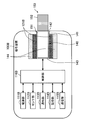
- FIG. 2 is a schematic diagram schematically showing a second configuration example of the suction device.
- the suction device 100B according to this configuration example includes a power supply unit 111B, a sensor unit 112B, a notification unit 113B, a storage unit 114B, a communication unit 115B, a control unit 116B, a heating unit 121B, a holding unit 140, and a holding unit 140. Includes insulation 144.
- Each of the power supply unit 111B, the sensor unit 112B, the notification unit 113B, the storage unit 114B, the communication unit 115B, and the control unit 116B is substantially the same as the corresponding components included in the suction device 100A according to the first configuration example. Is.
- the holding portion 140 has an internal space 141, and holds the stick-type base material 150 while accommodating a part of the stick-type base material 150 in the internal space 141.
- the holding portion 140 has an opening 142 that communicates the internal space 141 to the outside, and holds the stick-type base material 150 inserted into the internal space 141 from the opening 142.
- the holding portion 140 is a tubular body having an opening 142 and a bottom portion 143 as a bottom surface, and defines a columnar internal space 141.
- the holding portion 140 also has a function of defining a flow path of air supplied to the stick-type base material 150.
- the air inflow hole which is the inlet of air to such a flow path, is arranged at, for example, the bottom 143.
- the air outflow hole which is an outlet for air from such a flow path, is an opening 142.
- the stick-type base material 150 includes a base material portion 151 and a mouthpiece portion 152.
- the base material portion 151 contains an aerosol source.
- the aerosol source is not limited to a liquid, but may be a solid.
- the heating unit 121B has the same configuration as the heating unit 121A according to the first configuration example. However, in the example shown in FIG. 2, the heating portion 121B is formed in a film shape and is arranged so as to cover the outer periphery of the holding portion 140. Then, when the heating unit 121B generates heat, the base material portion 151 of the stick-type base material 150 is heated from the outer periphery to generate an aerosol.
- the heat insulating portion 144 prevents heat transfer from the heating portion 121B to other components.
- the heat insulating portion 144 is made of a vacuum heat insulating material, an airgel heat insulating material, or the like.
- suction device 100B has been described above.
- the configuration of the suction device 100B is not limited to the above, and various configurations exemplified below can be adopted.
- the heating portion 121B may be configured in a blade shape and may be arranged so as to project from the bottom portion 143 of the holding portion 140 into the internal space 141. In that case, the blade-shaped heating portion 121B is inserted into the base material portion 151 of the stick-type base material 150, and the base material portion 151 of the stick-type base material 150 is heated from the inside. As another example, the heating portion 121B may be arranged so as to cover the bottom portion 143 of the holding portion 140. Further, the heating portion 121B is a combination of two or more of a first heating portion that covers the outer periphery of the holding portion 140, a blade-shaped second heating portion, and a third heating portion that covers the bottom portion 143 of the holding portion 140. May be configured as.
- the holding portion 140 may include an opening / closing mechanism such as a hinge that opens / closes a part of the outer shell forming the internal space 141. Then, the holding portion 140 may sandwich the stick-type base material 150 inserted in the internal space 141 by opening and closing the outer shell.
- the heating unit 121B may be provided at the sandwiching portion of the holding unit 140 and may be heated while pressing the stick-type base material 150.
- the means for atomizing the aerosol source is not limited to heating by the heating unit 121B.
- the means for atomizing the aerosol source may be induction heating.
- the suction device 100B may further include a heating unit 121A, a liquid induction unit 122, a liquid storage unit 123, and an air flow path 180 according to the first configuration example, and the air outflow hole 182 of the air flow path 180. May also serve as an air inflow hole to the internal space 141.
- the mixed fluid of the aerosol and air generated by the heating unit 121A flows into the internal space 141, is further mixed with the aerosol generated by the heating unit 121B, and reaches the user's oral cavity.
- FIG. 3 is a block diagram showing an example of the configuration of the system 1 according to the embodiment of the present invention. As shown in FIG. 3, the system 1 includes a suction device 100 and a terminal device 200.
- the suction device 100 and the terminal device 200 are devices that are related to each other.
- the suction device 100 and the terminal device 200 are related in that they are used by the same user.
- the suction device 100 and the terminal device 200 are related in that they are associated in advance by making an authentication connection for wireless communication or the like.
- the suction device 100 and the terminal device 200 are related in that they can communicate with each other.
- the authentication connection is a means for establishing a connection between the suction device 100 and the terminal device 200.
- the suction device 100 and the terminal device 200 exchange identification information (for example, SSID (Service Set Identifier)) with each other, and perform key information for encrypting / decrypting information to be transmitted / received. Includes shared processing, etc.
- identification information for example, SSID (Service Set Identifier)
- the suction device 100 is a device that generates a substance to be sucked by a user.
- the user sucking the substance produced by the suction device 100 using the suction device 100 is also hereinafter simply referred to as suction (puff) or suction operation.
- the suction device 100 may take any configuration example of the first configuration example or the second configuration example described above. That is, the suction device 100 according to the present embodiment has the same configuration as either the suction device 100A or the suction device 100B, or a modification of these configuration examples.
- the power supply unit 110 and the cartridge 120 can be electrically and / or mechanically (including physically) connected to each other.
- the power supply unit 110 and the cartridge 120 are detachably configured. Typically, the suction is performed by the user with the power supply unit 110 and the cartridge 120 connected to each other. Note that connecting the power supply unit 110 and the cartridge 120 is also referred to as mounting the cartridge 120 below.
- the aerosol source accumulated in the cartridge 120 can be exhausted.
- the old cartridge 120 is removed and replaced with a new cartridge 120.
- the cartridge 120 and the flavoring cartridge 130 can be electrically and / or mechanically (including physically) connected to each other.
- the cartridge 120 and the flavoring cartridge 130 are detachably configured. Typically, the user sucks in a state where the power supply unit 110 and the cartridge 120 are connected and the cartridge 120 and the flavoring cartridge 130 are connected.
- connecting the cartridge 120 and the flavoring cartridge 130 is also referred to hereinafter as mounting the flavoring cartridge 130.
- the flavor components accumulated in the flavoring cartridge 130 can be depleted.
- the old flavor-imparting cartridge 130 is removed and replaced with a new flavor-imparting cartridge 130.
- the sensor unit 112 includes a position information acquisition unit that acquires position information indicating the position of the suction device 100.
- the position information acquisition unit receives, for example, a GNSS signal from a GNSS (Global Navigation Satellite System) satellite (for example, a GPS signal from a GPS (Global Positioning System) satellite) and obtains position information consisting of the latitude and longitude of the device. To detect.
- the position information acquisition unit may not have a function of detecting the position information by itself, and may acquire the position information detected by the terminal device 200 described later.
- the sensor unit 112 may detect information indicating the movement of the suction device 100.
- Information indicating the movement of the suction device 100 includes speed, acceleration, angular velocity, and the like.
- the sensor unit 112 may include a speed sensor, an acceleration sensor, and a gyro sensor.
- the sensor unit 112 may detect the state of the power supply unit 111.
- the sensor unit 112 may be configured to detect the SOC (State of Charge, state of charge), current integrated value, voltage, and the like of the power supply unit 111.
- the current integration value may be obtained by the current integration method, the SOC-OCV (0pen Circuit Voltage, open circuit voltage) method, or the like.
- the sensor unit 112 may detect whether or not the interface provided in the suction device 100 is used. As an example, the sensor unit 112 may detect the insertion / removal of a USB (Universal Serial Bus) cable.
- USB Universal Serial Bus
- the sensor unit 112 may detect the state of the heating unit 121. As an example, the sensor unit 112 may detect the temperature of the heating unit 121 based on the electric resistance value of the conductive track of the heating unit 121. In the suction device 100B according to the second configuration example, the temperature of the stick-type base material 150 may be estimated based on the temperature of the heating unit 121, and the temperature of the heating unit 121 may be the temperature of the stick-type base material 150. It may be treated as temperature.
- the sensor unit 112 may detect the state of the cartridge 120. As an example, the sensor unit 112 may detect the weight of the aerosol source stored in the liquid storage unit 123. As another example, the sensor unit 112 may detect the height of the liquid level in the liquid storage unit 123. Further, the sensor unit 112 may detect whether or not the cartridge 120 is mounted and the identification information of the mounted cartridge 120, and detects whether or not the cartridge 120 has been replaced based on these detection results. May be good. Further, the sensor unit 112 may detect the state of the heating unit 121 and detect the state of the cartridge 120 based on the detected state of the heating unit 121.
- the sensor unit 112 may detect the state of the flavoring cartridge 130. As an example, the sensor unit 112 may detect the weight of the flavor source 131. Further, the sensor unit 112 may detect whether or not the flavor-imparting cartridge 130 is attached and the identification information of the attached flavor-imparting cartridge 130, and whether the flavor-imparting cartridge 130 has been replaced based on these detection results. You may detect whether or not.
- the sensor unit 112 has an operation unit that accepts operations by the user.
- An example of an operation unit is a button.
- One of the buttons provided on the suction device 100 as an operation unit is also referred to as a power button below.
- the operation unit may be composed of a touch sensor. In that case, the operating state of the suction device 100 changes when a touch to the touch sensor is detected.
- the configuration of the operation unit is not limited to the button and the touch sensor, and any configuration such as a toggle switch or a rotary switch can be adopted.
- the operating state of the suction device 100 may change when suction by the user is detected. Further, the operating state of the suction device 100 may be changed by detecting an action of changing the position or posture of the suction device 100, such as a user applying a predetermined movement to the suction device 100.
- the operating state of the suction device 100 is classified into a sleep state, a standby state, an aerosol generation state (suction state), a low voltage state (LowVol state), a charging state, and an error state.
- the sleep state is a state in which some of the functions of the suction device 100 can be executed. For example, in the sleep state, among the functions of the sensor unit 112, only the function of detecting the operation of activating the suction device 100 may be executable. As a result, it is possible to minimize the power consumption while making it possible to transition to the standby state at an arbitrary timing.
- the standby state is a state in which all the functions of the suction device 100 can be executed.
- the standby state is a state in which heating is not performed by the heating unit 121.
- the suction device 100 can execute heating by the heating unit 121, notification by the notification unit 113, and communication by the communication unit 115.
- the aerosol generation state is a state in which an aerosol sucked by the user is being generated.
- the aerosol generation state is a state in which heating is performed by the heating unit 121.
- the low voltage state (LowVol state) is a state in which the suction device 100 cannot operate due to insufficient power remaining.
- the suction device 100 transitions to a low voltage state.
- the charging state is a state in which the suction device 100 is being charged from an external power source (not shown).
- the charging state is a state in which the power supply unit 111 is charged from an external power source (not shown).
- the error state is a state in which an error is detected in the suction device 100.
- the error state is a state in which it is detected that an error has occurred in a part of the functions of the suction device 100.
- the triggers for transitioning the operating state can be considered in various ways. Hereinafter, the present embodiment will be described while supposing the first to third types of suction devices 100 in which the triggers for transitioning the operating states are different.
- the first type suction device 100 is configured as the suction device 100A according to the first configuration example.
- the first type suction device 100 transitions to the aerosol generation state when the suction operation by the user is detected in the standby state.
- the first type suction device 100 transitions to the standby state when it is detected that the suction operation by the user is completed in the aerosol generation state.
- the second type suction device 100 is configured as the suction device 100A according to the first configuration example.
- the second type suction device 100 transitions to the standby state when the power button is pressed in the sleep state. Then, the second type suction device 100 transitions to the aerosol generation state when the suction operation by the user is detected in the standby state.
- the second type suction device 100 transitions to the standby state when it is detected that the suction operation by the user is completed in the aerosol generation state. Then, the second type suction device 100 transitions to the sleep state when the power button is pressed in the standby state.
- the third type suction device 100 is configured as the suction device 100B according to the second configuration example.
- the third type suction device 100 transitions to the aerosol generation state when the power button is pressed in the sleep state.
- the temperature of the stick-type base material 150 (more accurately, the temperature of the base material portion 151 to be heated by the heating unit 121) has reached a predetermined temperature (hereinafter, also referred to as a suctionable temperature) (for example, exceeding). In that case, the user can suck.
- the heating performed by the third type suction device 100 until the temperature of the stick-type base material 150 reaches a predetermined temperature is also referred to as preheating.
- the third type suction device 100 transitions to the standby state when a predetermined time elapses in the aerosol generation state. Then, the third type suction device 100 transitions to the sleep state when the stick type base material 150 is pulled out in the standby state.
- the control unit 116 of the suction device 100 according to the present embodiment includes the components shown in FIG.
- FIG. 4 is a block diagram showing an example of a logical configuration of the control unit 116 of the suction device 100 according to the present embodiment.
- the control unit 116 includes a system control unit 301, a power supply control unit 303, a sensor control unit 305, a notification control unit 307, a memory control unit 309, and a communication control unit 311.
- the system control unit 301 provides each function included in the control unit 116 (in the example of FIG. 4, the power supply control unit 303, the sensor control unit 305, the notification control unit 307, the storage control unit 309, and the communication control unit 311). Control. Further, the system control unit 301 controls execution of various control programs, an embedded operating system (0S) program, and the like, for example. For example, when the system control unit 301 detects various request signals such as a start instruction, it reads a program, an OS code, and the like, allocates the processing time and resources required for executing them, and so on, so that the program can be executed in units of execution. Process a process.
- the system control unit 301 is not limited to these examples, and can control various functions and various processes required for the operation of the suction device 100.
- the power supply control unit 303 controls, for example, power supply from the power supply unit 111 to other components included in the suction device 100 and charging of the power supply unit 111.
- the power supply control unit 303 controls, for example, the power supply from the power supply unit 111 to the heating unit 121.
- the power supply control unit 303 supplies power to the heating unit 121 when a suction operation is detected or when a predetermined button is pressed.
- the power supply control unit 303 may control the amount of heat supplied by the heating unit 121 by controlling the amount of power supplied from the power supply unit 111 to the heating unit 121.
- the power supply control unit 303 controls charging to the power supply unit 111 from an external power supply (not shown).
- the power supply control unit 303 may execute a function of protecting the power supply unit 111, for example.
- the power supply control unit 303 is not limited to these examples, and can execute various controls on the power supply unit 111.
- the sensor control unit 305 controls the sensor unit 112. For example, the sensor control unit 305 causes the sensor unit 112 to detect various types of information.
- the sensor control unit 305 may control the information detection timing by the sensor unit 112.
- the sensor control unit 305 may detect the state of the cartridge 120 and the state of the flavoring cartridge 130 at predetermined time intervals or every time the number of suctions reaches the predetermined number of times.
- the sensor control unit 305 may detect the position information or the state of the heating unit 121 when the suction operation is detected.
- the notification control unit 307 controls the notification unit 113.
- the notification control unit 307 controls the notification unit 113 so as to notify information by an image, sound, light, or vibration.
- the notification control unit 307 notifies the information indicating the operating state, or notifies the information indicating the information detected by the sensor unit 112.
- the memory control unit 309 controls the storage unit 114.
- the storage control unit 309 stores information in the storage unit 114 and reads out the information stored in the storage unit 114.
- the communication control unit 311 controls the communication unit 115. Specifically, the communication control unit 311 controls the communication between the suction device 100 and the terminal device 200. For example, the communication control unit 311 executes the above-mentioned authentication connection. After that, the communication control unit 311 transmits / receives information to / from the terminal device 200.
- the control unit 116 controls the suction device 100 by each of the components described above. That is, the power supply unit 110 including the control unit 116 is an example of the control device in the present invention.
- the terminal device 200 is an information processing device operated by a user.
- the terminal device 200 functions as a device (hereinafter, also referred to as a UI device) that serves as an interface with the user.
- the terminal device 200 is an example of another device in the present invention.
- the terminal device 200 is composed of a smartphone, a tablet terminal, a wearable device, or the like.
- the terminal device 200 includes a sensor unit 210, a notification unit 220, a communication unit 230, a storage unit 240, and a control unit 250.
- the sensor unit 210 detects various information related to the terminal device 200. Then, the sensor unit 210 outputs the detected information to the control unit 250.
- the sensor unit 210 includes an input unit that receives input of information from the user.
- the input unit includes, for example, at least one of a button, a keyboard, a touch panel, or a microphone.
- the sensor unit 210 includes a position information acquisition unit that acquires position information indicating the position of the terminal device 200.
- the position information acquisition unit receives, for example, a GNSS signal from a GNSS satellite (for example, a GPS signal from a GPS satellite) and detects position information consisting of the latitude and longitude of the device.
- the notification unit 220 notifies the user of the information.
- the notification unit 220 includes at least one of a display device for displaying information, a light emitting device for emitting light, a vibrating device for vibrating, and a sound output device for outputting sound.
- An example of a display device is a display.
- An example of a light emitting device is an LED.
- An example of a vibrating device is an eccentric motor.
- An example of a sound output device is a speaker.
- the notification unit 220 notifies the user of the information by outputting the information input from the control unit 250.
- the notification unit 220 displays information to be notified to the user, emits light in a light emitting pattern according to the information to be notified to the user, vibrates in a vibration pattern according to the information to be notified to the user, or notifies the user.
- the information to be output is output by voice.
- the communication unit 230 is a communication interface for transmitting and receiving information between the terminal device 200 and another device.
- the communication unit 230 performs communication conforming to any wired or wireless communication standard.
- a communication standard for example, a wireless LAN (Local Area Network), a wired LAN, Wi-Fi (registered trademark), Bluetooth (registered trademark), or the like can be adopted.
- the communication unit 230 wirelessly transmits and receives information to and from the suction device 100.
- the storage unit 240 stores various information for the operation of the terminal device 200.
- the storage unit 240 is composed of a non-volatile storage medium such as a flash memory.
- the control unit 250 functions as an arithmetic processing unit and a control device, and controls the overall operation in the terminal device 200 according to various programs.
- the control unit 250 is realized by, for example, an electronic circuit such as a CPU (Central Processing Unit) and a microprocessor.
- the control unit 250 may include a ROM (Read Only Memory) for storing programs to be used, calculation parameters, and the like, and a RAM (Random Access Memory) for temporarily storing parameters and the like that change as appropriate.
- ROM Read Only Memory
- RAM Random Access Memory
- the terminal device 200 executes various processes based on the control by the control unit 250.
- the processing of information detected by the sensor unit 210, the notification of information by the notification unit 220, the transmission and reception of information by the communication unit 230, and the storage and reading of information by the storage unit 240 are examples of the processing controlled by the control unit 250. ..
- Other processes executed by the terminal device 200, such as input of information to each component and processing based on the information output from each component, are also controlled by the control unit 250.
- the function of the control unit 250 may be realized by using an application.
- the application may be pre-installed or downloaded. Further, the function of the control unit 250 may be realized by PWA (Progressive Web Apps).
- the suction device 100 detects a predetermined operation related to the suction device 100.
- the predetermined operation here is an operation performed when the suction device 100 is used.
- the predetermined operation can be detected by the sensor unit 112.
- Such a predetermined operation is also referred to as a use operation below.
- the operation used may include at least one of the operations exemplified below.
- the use operation may be an operation performed by the user with respect to the suction device 100.
- the use operation may be an operation performed on the suction device 100 by a third party other than the user.
- the use operation may include an operation of charging the suction device 100.
- the power supply unit 111 may be charged by being connected to an external power supply by a USB (Universal Serial Bus) cable or the like. Further, the power supply unit 111 may be charged in a state of being disconnected from the device on the power transmission side by the wireless power transmission technology. Alternatively, only the power supply unit 111 may be removed from the suction device 100, or may be replaced with a new power supply unit 111.
- the sensor unit 112 can detect these operations by detecting the state of the power supply unit 111. For example, the sensor unit 112 can periodically detect the remaining power of the power supply unit 111 to detect that the charging operation has been performed when the remaining power has increased.
- the use operation may include a suction operation.
- the sensor unit 112 detects a negative pressure due to suction by the user, it detects that the suction operation has been performed.
- the use operation may include an operation of causing the suction device 100 to generate an aerosol sucked by the user.
- the operation of causing the suction device 100 to generate the aerosol sucked by the user may include the operation of putting the suction device 100 into the aerosol generation state.
- the operation of putting the first type suction device 100 into the aerosol generation state is a suction operation in the standby state.
- the operation of bringing the second type suction device 100 into the aerosol generation state is a suction operation in the standby state.
- the operation of putting the third type suction device 100 into the aerosol generation state is an operation of pressing the power button in the sleep state.
- the operation of causing the suction device 100 to generate the aerosol sucked by the user may include the operation of putting the suction device 100 into the standby state.
- the operation of putting the suction device 100 of the second type into the standby state is an operation of pressing the power button in the sleep state.
- the use operation may include an operation of operating an operation unit provided in the suction device 100 for receiving an operation by a user.
- the use operation may include an operation of changing the position or posture of the suction device 100.
- the sensor unit 112 detects an operation of changing the position of the suction device 100 based on at least one of the speed, acceleration, or position information of the suction device 100.
- the sensor unit 112 detects an operation of changing the posture of the suction device 100 based on the angular velocity of the suction device 100.
- the predetermined operation may include an operation executed by the suction device 100. More specifically, the predetermined operation may include an operation performed by the suction device 100 based on an operation performed by the user on the suction device 100. The predetermined operation may include an operation in which the suction device 100 produces a substance to be sucked by the user based on the suction of the user. Further, the predetermined operation may include a heating operation by the heating unit 121 provided in the suction device 100. Further, the predetermined operation may include an operation in which the suction device 100 detects the speed or position of the own device.
- the suction device 100 transmits information indicating the state of the suction device 100 to the terminal device 200 when the period during which the use operation is not detected exceeds a predetermined threshold value.
- the used operation may include a plurality of types of operations as described above. Then, the suction device 100 transmits information indicating the state of the suction device 100 to the terminal device 200 when the period during which no use operation is detected among the plurality of types of use operations exceeds a predetermined threshold value. Therefore, it is possible to collect the information of the suction device 100 even when the suction device 100 is not used.
- the beginning of the period in which the usage operation is not detected is typically the timing when the usage operation was detected last time (that is, last).
- the beginning of the period in which the usage operation is not detected may be the timing when the sleep state or the low voltage state is finally reached.
- the predetermined threshold value can take various values such as minutes, hours, days, and weeks.
- the suction device 100 may set a predetermined threshold value for each use operation. For example, the suction device 100 may set a value as a predetermined threshold value according to the type of the last detected use operation.
- the predetermined threshold value is also referred to as a transmission trigger threshold value below.
- Information indicating the state of the suction device 100 is also referred to as state information below.
- the terminal device 200 receives the status information, the terminal device 200 notifies the user of the status information. For example, the terminal device 200 displays state information and outputs audio. This allows the user to recognize the state of the suction device 100.
- the state information is transmitted when the period during which the usage operation is not detected exceeds the transmission trigger threshold value. Therefore, the user can easily recognize the state of the suction device 100 that has been left unused for a period exceeding the transmission trigger threshold value.
- the suction device 100 In the sleep state, it may be difficult for the suction device 100 to determine whether or not the period during which the use operation is not detected exceeds the transmission trigger threshold value, or to transmit the state information. In that case, when the suction device 100 is in the sleep state, the suction device 100 periodically returns to the standby state, determines whether or not the period during which the use operation is not detected exceeds the transmission trigger threshold value, and states information according to the determination result. May be sent. In this case, after the determination or the transmission of the state information, the suction device 100 transitions to the sleep state again.
- the suction device 100 can return from the sleep state to the standby state by using the operation by the user as a trigger.
- the suction device 100 determines whether or not the period during which the use operation is not detected exceeds the transmission trigger threshold value at the time of returning. You may judge. For example, the suction device 100 determines whether or not the time interval between the use operation that triggered the return and the last detected use operation before the return exceeds the transmission trigger threshold value. Then, the suction device 100 may transmit the state information according to the determination result.
- the state information may include at least one of the information described below.
- the suction device 100 can generate a substance to be sucked by the user by consuming the contents accumulated in the first base material.
- the cartridge 120 corresponds to the first base material
- the aerosol source corresponds to the contents accumulated in the first base material
- the aerosol is sucked by the user.
- the state information may include information indicating the state of the first base material, that is, information indicating the state of the cartridge 120. By recognizing the information indicating the state of the cartridge 120 via the terminal device 200, the user can easily determine, for example, whether or not to replace the cartridge 120 of the suction device 100 that has been left for a long time. It will be possible.
- the state information may include at least one of the information exemplified below as information indicating the state of the cartridge 120.
- the information indicating the state of the cartridge 120 may include information indicating the remaining amount of the aerosol source stored in the cartridge 120.
- the remaining amount of the aerosol source stored in the cartridge 120 can be detected by detecting the weight of the aerosol source stored in the liquid storage unit 123.
- the remaining amount of the aerosol source accumulated in the cartridge 120 may be estimated based on the number of suctions.
- the information indicating the state of the cartridge 120 may include information indicating the elapsed time since the last generation of the aerosol using the cartridge 120.
- the elapsed time since the last generation of the aerosol using the cartridge 120 is also referred to as the elapsed time since the last suction operation was detected with the cartridge 120 mounted.
- the information indicating the state of the cartridge 120 may include information indicating the elapsed time from the state in which the aerosol can be produced by using the cartridge 120.
- the state in which the aerosol can be generated by using the cartridge 120 is, for example, a state in which the cartridge 120 is attached to the power supply unit 110. That is, the information indicating the state of the cartridge 120 may include information indicating the period during which the cartridge 120 is mounted.
- the information indicating the state of the cartridge 120 may include information indicating the state of the heating unit 121.
- Examples of the information indicating the state of the heating unit 121 include information indicating the temperature of the heating unit 121 and the temperature change per unit time.
- the suction device 100 adds a predetermined component added to the second base material to the substance produced by consuming the contents accumulated in the first base material. By imparting, it is possible to generate a substance to which a predetermined component to be sucked by the user is imparted.
- the predetermined component added to the second base material includes, for example, a flavor component.
- the cartridge 120 corresponds to the first base material
- the aerosol source corresponds to the contents accumulated in the first base material
- the flavoring cartridge 130 corresponds to the first base material. It corresponds to the base material of No. 2 and corresponds to the substance to which the aerosol is sucked by the user.
- the state information may include information indicating the state of the second base material, that is, information indicating the state of the flavoring cartridge 130.
- information indicating the state of the flavoring cartridge 130 In addition to the flavor component, other components may be added to the flavor-imparting cartridge.
- the state information may include at least one of the information exemplified below as information indicating the state of the flavoring cartridge 130.
- the information indicating the state of the flavor imparting cartridge 130 may include information indicating the remaining amount of the flavor component accumulated in the flavor imparting cartridge 130.
- the remaining amount of the flavor component accumulated in the flavor-imparting cartridge 130 can be detected by detecting the weight of the flavor source 131.
- the remaining amount of the flavor component accumulated in the flavor-imparting cartridge 130 may be estimated based on the number of suctions.
- the information indicating the state of the flavoring cartridge 130 may include information indicating the elapsed time since the last generation of the aerosol using the flavoring cartridge 130.
- the elapsed time from the last generation of the aerosol using the flavor-imparting cartridge 130 is also referred to as the elapsed time from the last detection of the suction operation with the flavor-imparting cartridge 130 attached.
- the information indicating the state of the flavor-imparting cartridge 130 may include information indicating the elapsed time from the state in which the flavor component can be applied to the aerosol by using the flavor-imparting cartridge 130.
- the state in which the flavoring component can be added to the aerosol by using the flavoring cartridge 130 is, for example, a state in which the flavoring cartridge 130 is attached to the cartridge 120 mounted on the power supply unit 110. That is, the information indicating the state of the cartridge 120 may include information indicating the period during which the flavoring cartridge 130 is attached.
- the state information may include information on suction performed in the past using the suction device 100. By recognizing the information about the suction performed in the past by using the suction device 100 through the terminal device 200, for example, whether or not the suction device 100 that has been left for a long time can be used as it is. Can be easily determined.
- the state information may include at least one of the information exemplified below as information regarding suction performed in the past using the suction device 100.
- the information regarding the suction performed in the past using the suction device 100 may include information indicating the cumulative number of suctions performed using the suction device 100.
- the cumulative number of times is reset, for example, when the suction device 100 is manufactured, when the suction device 100 is last charged, when the cartridge 120 is last replaced, or when the suction device 100 is finally replaced with the flavoring cartridge 130. It can be done at various timings.
- the information regarding the suction performed in the past using the suction device 100 may include information indicating the elapsed time since the last suction performed using the suction device 100. That is, the information regarding the suction performed in the past using the suction device 100 may include information indicating the elapsed time since the last suction operation was detected.
- the information regarding the suction performed in the past using the suction device 100 may include information indicating the time when the suction using the suction device 100 was last performed. That is, the information regarding the suction performed in the past using the suction device 100 may include information indicating the time when the suction operation was last detected.
- the state information may include various other information.
- the state information may include at least one of the information exemplified below.
- the state information may include information indicating the remaining amount of electric power stored in the suction device 100.
- the user may use, for example, the suction device 100 that has been left for a long time without charging. It becomes possible to easily determine whether or not it is.
- the state information may include information indicating the position of the suction device 100.
- the user can easily find, for example, the suction device 100 which has been left for a long time and whose whereabouts are unknown.
- FIG. 5 is a flowchart showing an example of the flow of the state management process executed by the suction device 100 according to the present embodiment.
- the suction device 100 starts detecting the use operation (step S102).
- the suction device 100 starts counting by the time counter (step S104).
- the time counter is a counter whose count value is incremented (that is, counted up) according to the passage of time.
- the suction device 100 determines whether or not the use operation is detected (step S106).
- step S106 When it is determined that the use operation is detected (step S106: YES), the suction device 100 resets the time counter (step S114). After that, the process returns to step S104.
- step S106 when it is determined that the use operation is not detected (step S106: NO), the suction device 100 counts up the time counter (step S108). Next, the suction device 100 determines whether or not the period during which the use operation indicated by the count value of the time counter is not detected exceeds the transmission trigger threshold value (step S110).
- step S110 When it is determined that the period during which the use operation is not detected exceeds the transmission trigger threshold value (step S110: YES), the suction device 100 transmits the state information to the terminal device 200 (step S112). The suction device 100 then resets the time counter (step S114). After that, the process returns to step S104.
- step S110: NO if it is determined that the period during which the use operation is not detected does not exceed the transmission trigger threshold value (step S110: NO), the process returns to step S106 again.
- the power supply unit 110 functions as a control device, but the present invention is not limited to such an example.
- any one of the cartridge 120, the flavoring cartridge 130, or the terminal device 200 may function as a control device.
- other devices that are neither the suction device 100 nor the terminal device 200 may function as the control device.
- the function as a control device may be shared by a plurality of devices such as the power supply unit 110 and the terminal device 200.
- the sensor unit 112 is arranged in the power supply unit 110, but the present invention is not limited to such an example.
- at least a part of the sensor unit 112 may be arranged in the cartridge 120 or the flavoring cartridge 130.
- the sensor unit 112 that detects the state of the cartridge 120 may be arranged in the cartridge 120, and the information detected by the sensor unit 112 may be transmitted to the control unit 116. The same applies to the sensor unit 112 that detects the state of the flavoring cartridge 130.
- each device described in the present specification may be realized by using software, hardware, or a combination of software and hardware.
- the programs constituting the software are stored in advance in, for example, a recording medium (non-transitory media) provided inside or outside each device. Then, each program is read into RAM at the time of execution by a computer and executed by a processor such as a CPU.
- the recording medium is, for example, a magnetic disk, an optical disk, a magneto-optical disk, a flash memory, or the like.
- the above-mentioned computer program may be distributed via, for example, a network without using a recording medium.
Landscapes
- Engineering & Computer Science (AREA)
- Computer Networks & Wireless Communication (AREA)
- Devices For Medical Bathing And Washing (AREA)
- Telephone Function (AREA)
- Medicinal Preparation (AREA)
- Medical Preparation Storing Or Oral Administration Devices (AREA)
- Disinfection, Sterilisation Or Deodorisation Of Air (AREA)
Abstract
Description
吸引装置は、ユーザにより吸引される物質を生成する装置である。以下では、吸引装置により生成される物質が、エアロゾルであるものとして説明する。他に、吸引装置により生成される物質は、気体であってもよい。
図1は、吸引装置の第1の構成例を模式的に示す模式図である。図1に示すように、本構成例に係る吸引装置100Aは、電源ユニット110、カートリッジ120、及び香味付与カートリッジ130を含む。電源ユニット110は、電源部111A、センサ部112A、通知部113A、記憶部114A、通信部115A、及び制御部116Aを含む。カートリッジ120は、加熱部121A、液誘導部122、及び液貯蔵部123を含む。香味付与カートリッジ130は、香味源131、及びマウスピース124を含む。カートリッジ120及び香味付与カートリッジ130には、空気流路180が形成される。
図2は、吸引装置の第2の構成例を模式的に示す模式図である。図2に示すように、本構成例に係る吸引装置100Bは、電源部111B、センサ部112B、通知部113B、記憶部114B、通信部115B、制御部116B、加熱部121B、保持部140、及び断熱部144を含む。
<2.1.構成例>
図3は、本発明の一実施形態に係るシステム1の構成の一例を示すブロック図である。図3に示すように、システム1は、吸引装置100、及び端末装置200を含む。
吸引装置100は、ユーザにより吸引される物質を生成する装置である。ユーザが吸引装置100を用いて、吸引装置100により生成された物質を吸引することを、以下では単に吸引(パフ)又は吸引動作とも称する。
電源ユニット110とカートリッジ120とは、互いに電気的及び/又は機械的(物理的を含む)に接続可能である。電源ユニット110とカートリッジ120とは、着脱可能に構成されている。典型的には、電源ユニット110とカートリッジ120とが接続された状態で、ユーザによる吸引が行われる。なお、電源ユニット110とカートリッジ120とを接続することを、以下ではカートリッジ120を装着するとも称する。
センサ部112は、吸引装置100の位置を示す位置情報を取得する位置情報取得部を含む。位置情報取得部は、例えば、GNSS(Global Navigation Satellite System)衛星からのGNSS信号(例えば、GPS(Global Positioning System)衛星からのGPS信号)を受信して装置の緯度、及び経度から成る位置情報を検出する。位置情報取得部は、自身で位置情報を検出する機能を有していなくてもよく、後述する端末装置200により検出された位置情報を取得してもよい。
本実施形態に係る吸引装置100の制御部116は、図4に示す構成要素を含む。図4は、本実施形態に係る吸引装置100の制御部116の論理的な構成の一例を示すブロック図である。図4に示すように、制御部116は、システム制御部301、電源制御部303、センサ制御部305、通知制御部307、記憶制御部309、及び通信制御部311を含む。
端末装置200は、ユーザにより操作される情報処理装置である。端末装置200は、ユーザとのインタフェースとなる装置(以下、UI装置とも称する)として機能する。また、端末装置200は、本発明における他の装置の一例である。例えば、端末装置200は、スマートフォン、タブレット端末又はウェアラブルデバイス等により構成される。
(1)所定動作の検出
吸引装置100は、吸引装置100に関する所定動作を検出する。ここでの所定動作とは、吸引装置100を使用する際に行われる動作である。所定動作は、センサ部112により検出可能である。かかる所定動作を、以下では使用動作とも称する。使用動作は、以下に例示する動作の少なくともいずれかを含んでいてもよい。
吸引装置100は、使用動作が検出されない期間が所定の閾値を超えた場合に、吸引装置100の状態を示す情報を端末装置200に送信する。使用動作には、上記説明したように複数種類の動作が含まれていてもよい。そして、吸引装置100は、複数種類の使用動作のうちどの使用動作も検出されない期間が所定の閾値を超えた場合に、吸引装置100の状態を示す情報を端末装置200に送信する。よって、吸引装置100が使用されていない場合にも、吸引装置100の情報を収集することが可能となる。
吸引装置100は、第1の基材に蓄積された内容物を消費することで、ユーザに吸引される物質を生成し得る。第1の構成例に係る吸引装置100Aに関して言えば、カートリッジ120が第1の基材に相当し、エアロゾル源が第1の基材に蓄積された内容物に相当し、エアロゾルがユーザに吸引される物質に相当する。状態情報は、第1の基材の状態を示す情報、即ちカートリッジ120の状態を示す情報を含んでいてもよい。ユーザは、カートリッジ120の状態を示す情報を、端末装置200を介して認識することで、例えば、長時間放置されていた吸引装置100のカートリッジ120を交換すべきか否かを容易に判断することが可能となる。状態情報は、カートリッジ120の状態を示す情報として、以下に例示する情報の少なくともいずれかを含んでいてもよい。
吸引装置100は、第1の基材に蓄積された内容物を消費することで生成された物質に対し、第2の基材に添加された所定成分を付与することで、前記ユーザに吸引される所定成分が付与された物質を生成し得る。第2の基材に添加された所定成分は、例えば、香味成分を含む。第1の構成例に係る吸引装置100Aに関して言えば、カートリッジ120が第1の基材に相当し、エアロゾル源が第1の基材に蓄積された内容物に相当し、香味付与カートリッジ130が第2の基材に相当し、エアロゾルがユーザに吸引される物質に相当する。状態情報は、第2の基材の状態を示す情報、即ち香味付与カートリッジ130の状態を示す情報を含んでいてもよい。なお、香味付与カートリッジには、香味成分に加えて、他の成分が添加されていてもよい。ユーザは、香味付与カートリッジ130の状態を示す情報を、端末装置200を介して認識することで、例えば、長時間放置されていた吸引装置100の香味付与カートリッジ130を交換すべきか否かを容易に判断することが可能となる。状態情報は、香味付与カートリッジ130の状態を示す情報として、以下に例示する情報の少なくともいずれかを含んでいてもよい。
状態情報は、吸引装置100を用いて過去に行われた吸引に関する情報を含んでいてもよい。ユーザは、吸引装置100を用いて過去に行われた吸引に関する情報を、端末装置200を介して認識することで、例えば、長時間放置されていた吸引装置100をそのまま使用してよいか否かを容易に判断することが可能となる。状態情報は、吸引装置100を用いて過去に行われた吸引に関する情報として、以下に例示する情報の少なくともいずれかを含んでいてもよい。
状態情報は、その他の多様な情報を含んでいてもよい。例えば、状態情報は、以下に例示する情報の少なくともいずれかを含んでいてもよい。
図5は、本実施形態に係る吸引装置100により実行される状態管理処理の流れの一例を示すフローチャートである。図5に示すように、まず、吸引装置100は、使用動作の検出を開始する(ステップS102)。次いで、吸引装置100は、時間カウンタによるカウントを開始する(ステップS104)。なお、時間カウンタとは、時間経過に応じてカウント値がインクリメントされる(即ち、カウントアップされる)カウンタである。次に、吸引装置100は、使用動作が検出されたか否かを判定する(ステップS106)。
以上、添付図面を参照しながら本発明の好適な実施形態について詳細に説明したが、本発明はかかる例に限定されない。本発明の属する技術の分野における通常の知識を有する者であれば、請求の範囲に記載された技術的思想の範疇内において、各種の変更例または修正例に想到し得ることは明らかであり、これらについても、当然に本発明の技術的範囲に属するものと了解される。
100 吸引装置
110 電源ユニット
111 電源部
112 センサ部
113 通知部
114 記憶部
115 通信部
116 制御部
120 カートリッジ
121 加熱部
122 液誘導部
123 液貯蔵部
124 マウスピース
130 香味付与カートリッジ
131 香味源
140 保持部
141 内部空間
142 開口
143 底部
144 断熱部
150 スティック型基材
151 基材部
152 吸口部
180 空気流路
181 空気流入孔
182 空気流出孔
200 端末装置
210 センサ部
220 通知部
230 通信部
240 記憶部
250 制御部
301 システム制御部
303 電源制御部
305 センサ制御部
307 通知制御部
309 記憶制御部
311 通信制御部
Claims (14)
- 吸引装置を制御する制御装置であって、
前記吸引装置に関する所定動作を検出可能なセンサ部により前記所定動作が検出されない期間が所定の閾値を超えた場合に、前記吸引装置の状態を示す情報を他の装置に送信するよう前記吸引装置を制御する制御部、
を備える制御装置。 - 前記所定動作は、前記吸引装置に対してユーザにより行われる動作を含む、請求項1に記載の制御装置。
- 前記所定動作は、前記吸引装置を充電する動作、前記吸引装置を用いて吸引する動作、ユーザにより吸引される物質を前記吸引装置に生成させる動作、前記吸引装置に設けられた前記ユーザによる操作を受け付ける操作部を操作する動作、又は前記吸引装置の位置若しくは姿勢を変化させる動作、の少なくともいずれかを含む、請求項1又は2に記載の制御装置。
- 前記所定動作は、前記吸引装置が実行する動作を含む、請求項1~3のいずれか一項に記載の制御装置。
- 前記所定動作は、前記吸引装置が吸引される物質を生成する動作、前記吸引装置に備わる加熱部による加熱動作、前記吸引装置が自装置の速度を検出する動作、前記吸引装置が自装置の位置を検出する動作、の少なくともいずれかを含む、請求項1~4のいずれか一項に記載の制御装置。
- 前記吸引装置は、第1の基材に蓄積された内容物を消費することで、ユーザに吸引される物質を生成し、
前記吸引装置の状態を示す情報は、前記第1の基材の状態を示す情報を含む、請求項1~5のいずれか一項に記載の制御装置。 - 前記第1の基材の状態を示す情報は、前記第1の基材に蓄積された内容物の残量を示す情報、前記第1の基材を用いて前記物質を最後に生成してからの経過時間を示す情報、前記第1の基材を用いて前記物質を生成することが可能な状態になってからの経過時間を示す情報、又は前記吸引装置に備わる加熱部の状態を示す情報の、少なくともいずれかを含む、請求項6に記載の制御装置。
- 前記吸引装置は、第1の基材に蓄積された内容物を消費することで生成された物質に対し、第2の基材に添加された成分を付与することで、ユーザに吸引される香味成分が付与された物質を生成し、
前記吸引装置の状態を示す情報は、前記第2の基材の状態を示す情報を含む、請求項1~6のいずれか一項に記載の制御装置。 - 前記吸引装置の状態を示す情報は、前記吸引装置を用いて過去に行われた吸引に関する情報を含む、請求項1~8のいずれか一項に記載の制御装置。
- 前記吸引装置を用いて過去に行われた吸引に関する情報は、前記吸引装置を用いて行われた吸引の累積回数を示す情報、前記吸引装置を用いた吸引が最後に行われてからの経過時間を示す情報、又は前記吸引装置を用いた吸引が最後に行われた時刻を示す情報の、少なくともいずれかを含む、請求項9に記載の制御装置。
- 前記吸引装置の状態を示す情報は、前記吸引装置に蓄積された電力の残量を示す情報、又は前記吸引装置の位置を示す情報の、少なくともいずれかを含む、請求項1~10のいずれか一項に記載の制御装置。
- 前記制御部は、前記所定動作ごとに、前記所定の閾値を設定する、請求項1~11のいずれか一項に記載の制御装置。
- 吸引装置を制御する制御装置により実行される制御方法であって、
前記吸引装置に関する所定動作を検出可能なセンサ部により前記所定動作が検出されない期間が所定の閾値を超えた場合に、前記吸引装置の状態を示す情報を他の装置に送信するよう前記吸引装置を制御すること、
を含む制御方法。 - 吸引装置を制御するコンピュータを、
前記吸引装置に関する所定動作を検出可能なセンサ部により前記所定動作が検出されない期間が所定の閾値を超えた場合に、前記吸引装置の状態を示す情報を他の装置に送信するよう前記吸引装置を制御する制御部、
として機能させるためのプログラム。
Priority Applications (4)
| Application Number | Priority Date | Filing Date | Title |
|---|---|---|---|
| PCT/JP2020/014555 WO2021199159A1 (ja) | 2020-03-30 | 2020-03-30 | 制御装置、制御方法、及びプログラム |
| EP20928707.7A EP4079177A4 (en) | 2020-03-30 | 2020-03-30 | CONTROL DEVICE, CONTROL METHOD, AND PROGRAM |
| JP2022512900A JP7296009B2 (ja) | 2020-03-30 | 2020-03-30 | 制御装置、制御方法、及びプログラム |
| TW109122606A TWI842927B (zh) | 2020-03-30 | 2020-07-03 | 控制裝置、控制方法、及電腦程式產品 |
Applications Claiming Priority (1)
| Application Number | Priority Date | Filing Date | Title |
|---|---|---|---|
| PCT/JP2020/014555 WO2021199159A1 (ja) | 2020-03-30 | 2020-03-30 | 制御装置、制御方法、及びプログラム |
Publications (1)
| Publication Number | Publication Date |
|---|---|
| WO2021199159A1 true WO2021199159A1 (ja) | 2021-10-07 |
Family
ID=77930200
Family Applications (1)
| Application Number | Title | Priority Date | Filing Date |
|---|---|---|---|
| PCT/JP2020/014555 WO2021199159A1 (ja) | 2020-03-30 | 2020-03-30 | 制御装置、制御方法、及びプログラム |
Country Status (4)
| Country | Link |
|---|---|
| EP (1) | EP4079177A4 (ja) |
| JP (1) | JP7296009B2 (ja) |
| TW (1) | TWI842927B (ja) |
| WO (1) | WO2021199159A1 (ja) |
Cited By (3)
| Publication number | Priority date | Publication date | Assignee | Title |
|---|---|---|---|---|
| WO2023058739A1 (ja) * | 2021-10-08 | 2023-04-13 | 日本たばこ産業株式会社 | 香味吸引器具又はエアロゾル生成装置 |
| WO2023062789A1 (ja) * | 2021-10-14 | 2023-04-20 | 日本たばこ産業株式会社 | エアロゾル生成システム、制御方法、及びプログラム |
| WO2023089757A1 (ja) * | 2021-11-19 | 2023-05-25 | 日本たばこ産業株式会社 | 吸引装置 |
Citations (3)
| Publication number | Priority date | Publication date | Assignee | Title |
|---|---|---|---|---|
| JP2015532112A (ja) * | 2012-10-19 | 2015-11-09 | ニコベンチャーズ ホールディングス リミテッド | 電子式吸入装置 |
| WO2015192358A1 (zh) | 2014-06-19 | 2015-12-23 | 吉瑞高新科技股份有限公司 | 一种数据通信方法以及数据通信系统 |
| JP2019050809A (ja) * | 2014-11-10 | 2019-04-04 | 日本たばこ産業株式会社 | 非燃焼型香味吸引器 |
Family Cites Families (3)
| Publication number | Priority date | Publication date | Assignee | Title |
|---|---|---|---|---|
| US20150181945A1 (en) * | 2013-12-31 | 2015-07-02 | Martin Tremblay | Electronic vaping device |
| EA201892738A1 (ru) * | 2016-05-25 | 2019-05-31 | Джуул Лэбз, Инк. | Управление электронным испарителем |
| EP4046507A1 (en) * | 2018-03-29 | 2022-08-24 | Philip Morris Products S.A. | Fall response procedures for aerosol-generating devices |
-
2020
- 2020-03-30 JP JP2022512900A patent/JP7296009B2/ja active Active
- 2020-03-30 EP EP20928707.7A patent/EP4079177A4/en active Pending
- 2020-03-30 WO PCT/JP2020/014555 patent/WO2021199159A1/ja active Application Filing
- 2020-07-03 TW TW109122606A patent/TWI842927B/zh active
Patent Citations (3)
| Publication number | Priority date | Publication date | Assignee | Title |
|---|---|---|---|---|
| JP2015532112A (ja) * | 2012-10-19 | 2015-11-09 | ニコベンチャーズ ホールディングス リミテッド | 電子式吸入装置 |
| WO2015192358A1 (zh) | 2014-06-19 | 2015-12-23 | 吉瑞高新科技股份有限公司 | 一种数据通信方法以及数据通信系统 |
| JP2019050809A (ja) * | 2014-11-10 | 2019-04-04 | 日本たばこ産業株式会社 | 非燃焼型香味吸引器 |
Non-Patent Citations (1)
| Title |
|---|
| See also references of EP4079177A4 |
Cited By (3)
| Publication number | Priority date | Publication date | Assignee | Title |
|---|---|---|---|---|
| WO2023058739A1 (ja) * | 2021-10-08 | 2023-04-13 | 日本たばこ産業株式会社 | 香味吸引器具又はエアロゾル生成装置 |
| WO2023062789A1 (ja) * | 2021-10-14 | 2023-04-20 | 日本たばこ産業株式会社 | エアロゾル生成システム、制御方法、及びプログラム |
| WO2023089757A1 (ja) * | 2021-11-19 | 2023-05-25 | 日本たばこ産業株式会社 | 吸引装置 |
Also Published As
| Publication number | Publication date |
|---|---|
| JP7296009B2 (ja) | 2023-06-21 |
| EP4079177A1 (en) | 2022-10-26 |
| TW202135686A (zh) | 2021-10-01 |
| JPWO2021199159A1 (ja) | 2021-10-07 |
| TWI842927B (zh) | 2024-05-21 |
| EP4079177A4 (en) | 2023-09-27 |
Similar Documents
| Publication | Publication Date | Title |
|---|---|---|
| WO2021199159A1 (ja) | 制御装置、制御方法、及びプログラム | |
| WO2021240617A1 (ja) | 吸引装置、制御方法、及びプログラム | |
| JP7256330B2 (ja) | 端末装置、吸引装置、情報処理方法、及びプログラム | |
| WO2021234801A1 (ja) | 吸引装置、情報処理装置、及び制御方法 | |
| WO2021149178A1 (ja) | 吸引装置、制御方法、及びプログラム | |
| WO2022130563A1 (ja) | 吸引装置、端末装置、及びプログラム | |
| WO2022130546A1 (ja) | 吸引装置、端末装置、及びプログラム | |
| WO2021130902A1 (ja) | 制御装置、制御方法、及びプログラム | |
| WO2022208834A1 (ja) | 制御装置、端末装置及び情報処理方法 | |
| WO2022219677A1 (ja) | 情報処理装置、及び情報処理方法 | |
| WO2022208835A1 (ja) | 制御装置、端末装置及び情報処理方法 | |
| WO2021199406A1 (ja) | 情報処理装置、情報処理方法および情報処理プログラム | |
| WO2023079603A1 (ja) | エアロゾル生成装置の通知制御装置、エアロゾル生成装置の通知制御方法、及びエアロゾル生成装置の制御プログラム | |
| JP7355845B2 (ja) | 制御装置、制御方法、及びプログラム | |
| WO2021111578A1 (ja) | 制御装置、制御方法、及びプログラム | |
| WO2022249235A1 (ja) | 吸引装置、情報処理装置、サーバ装置、情報処理方法、及びプログラム | |
| WO2023026474A1 (ja) | 情報処理方法、エアロゾル生成システム、及びプログラム | |
| WO2024127661A1 (ja) | 吸引装置の制御方法、吸引装置の電源ユニット、及び、吸引装置のためのプログラム | |
| WO2024127660A1 (ja) | 吸引装置の制御方法、吸引装置の電源ユニット、及び、吸引装置のためのプログラム | |
| WO2023112218A1 (ja) | 制御装置、吸引装置、及び制御方法 | |
| WO2022219676A1 (ja) | 情報処理装置、及び情報処理方法 | |
| EP4368048A1 (en) | Information processing method, aerosol generation system, and program | |
| WO2023105614A1 (ja) | 情報処理装置、端末装置、及び情報処理方法 | |
| WO2023157123A1 (ja) | エアロゾル生成システム、制御方法、及びプログラム | |
| CN118450824A (zh) | 具有使用数据监测的气溶胶输送装置 |
Legal Events
| Date | Code | Title | Description |
|---|---|---|---|
| 121 | Ep: the epo has been informed by wipo that ep was designated in this application |
Ref document number: 20928707 Country of ref document: EP Kind code of ref document: A1 |
|
| ENP | Entry into the national phase |
Ref document number: 2022512900 Country of ref document: JP Kind code of ref document: A |
|
| WWE | Wipo information: entry into national phase |
Ref document number: 20928707 Country of ref document: EP |
|
| ENP | Entry into the national phase |
Ref document number: 2020928707 Country of ref document: EP Effective date: 20220721 |
|
| NENP | Non-entry into the national phase |
Ref country code: DE |