WO2022123728A1 - Dispositif de traitement d'informations, système de traitement d'informations, terminal de traitement d'informations, procédé de traitement d'informations et programme - Google Patents
Dispositif de traitement d'informations, système de traitement d'informations, terminal de traitement d'informations, procédé de traitement d'informations et programme Download PDFInfo
- Publication number
- WO2022123728A1 WO2022123728A1 PCT/JP2020/046058 JP2020046058W WO2022123728A1 WO 2022123728 A1 WO2022123728 A1 WO 2022123728A1 JP 2020046058 W JP2020046058 W JP 2020046058W WO 2022123728 A1 WO2022123728 A1 WO 2022123728A1
- Authority
- WO
- WIPO (PCT)
- Prior art keywords
- user
- unit
- information
- information processing
- registration
- Prior art date
Links
- 230000010365 information processing Effects 0.000 title claims abstract description 142
- 238000003672 processing method Methods 0.000 title claims description 6
- 230000004044 response Effects 0.000 claims abstract description 53
- 230000004913 activation Effects 0.000 claims abstract description 36
- 238000012795 verification Methods 0.000 claims description 15
- 238000010438 heat treatment Methods 0.000 description 81
- 238000004891 communication Methods 0.000 description 70
- 239000000443 aerosol Substances 0.000 description 36
- 230000006870 function Effects 0.000 description 26
- 239000000463 material Substances 0.000 description 21
- 238000012545 processing Methods 0.000 description 21
- 238000000034 method Methods 0.000 description 19
- 239000007788 liquid Substances 0.000 description 18
- 239000000796 flavoring agent Substances 0.000 description 13
- 235000019634 flavors Nutrition 0.000 description 13
- 238000010586 diagram Methods 0.000 description 12
- 230000004048 modification Effects 0.000 description 8
- 238000012986 modification Methods 0.000 description 8
- 230000008569 process Effects 0.000 description 7
- 230000006698 induction Effects 0.000 description 6
- 239000004973 liquid crystal related substance Substances 0.000 description 6
- 230000009471 action Effects 0.000 description 5
- 230000007704 transition Effects 0.000 description 5
- 241000208125 Nicotiana Species 0.000 description 4
- 235000002637 Nicotiana tabacum Nutrition 0.000 description 4
- 239000000470 constituent Substances 0.000 description 4
- 238000001514 detection method Methods 0.000 description 4
- 239000000047 product Substances 0.000 description 4
- 230000000391 smoking effect Effects 0.000 description 4
- 239000000126 substance Substances 0.000 description 4
- DNIAPMSPPWPWGF-UHFFFAOYSA-N Propylene glycol Chemical compound CC(O)CO DNIAPMSPPWPWGF-UHFFFAOYSA-N 0.000 description 3
- 230000003213 activating effect Effects 0.000 description 3
- 230000008859 change Effects 0.000 description 3
- 239000012530 fluid Substances 0.000 description 3
- 210000000214 mouth Anatomy 0.000 description 3
- PEDCQBHIVMGVHV-UHFFFAOYSA-N Glycerine Chemical compound OCC(O)CO PEDCQBHIVMGVHV-UHFFFAOYSA-N 0.000 description 2
- 238000000889 atomisation Methods 0.000 description 2
- 230000033228 biological regulation Effects 0.000 description 2
- 230000005540 biological transmission Effects 0.000 description 2
- 239000003990 capacitor Substances 0.000 description 2
- 238000010411 cooking Methods 0.000 description 2
- 230000000694 effects Effects 0.000 description 2
- 239000011810 insulating material Substances 0.000 description 2
- 239000007787 solid Substances 0.000 description 2
- HBBGRARXTFLTSG-UHFFFAOYSA-N Lithium ion Chemical compound [Li+] HBBGRARXTFLTSG-UHFFFAOYSA-N 0.000 description 1
- 239000000919 ceramic Substances 0.000 description 1
- 238000006243 chemical reaction Methods 0.000 description 1
- 230000002301 combined effect Effects 0.000 description 1
- 230000006866 deterioration Effects 0.000 description 1
- 239000003814 drug Substances 0.000 description 1
- 229940079593 drug Drugs 0.000 description 1
- 239000002657 fibrous material Substances 0.000 description 1
- 239000003365 glass fiber Substances 0.000 description 1
- 235000011187 glycerol Nutrition 0.000 description 1
- 230000020169 heat generation Effects 0.000 description 1
- 238000009413 insulation Methods 0.000 description 1
- 229910001416 lithium ion Inorganic materials 0.000 description 1
- 230000007246 mechanism Effects 0.000 description 1
- 239000006199 nebulizer Substances 0.000 description 1
- 239000011148 porous material Substances 0.000 description 1
- 239000000758 substrate Substances 0.000 description 1
- 150000005846 sugar alcohols Polymers 0.000 description 1
- 239000013589 supplement Substances 0.000 description 1
- 238000012546 transfer Methods 0.000 description 1
- 238000011144 upstream manufacturing Methods 0.000 description 1
- XLYOFNOQVPJJNP-UHFFFAOYSA-N water Substances O XLYOFNOQVPJJNP-UHFFFAOYSA-N 0.000 description 1
Images

Classifications
-
- A—HUMAN NECESSITIES
- A24—TOBACCO; CIGARS; CIGARETTES; SIMULATED SMOKING DEVICES; SMOKERS' REQUISITES
- A24F—SMOKERS' REQUISITES; MATCH BOXES; SIMULATED SMOKING DEVICES
- A24F40/00—Electrically operated smoking devices; Component parts thereof; Manufacture thereof; Maintenance or testing thereof; Charging means specially adapted therefor
- A24F40/50—Control or monitoring
- A24F40/53—Monitoring, e.g. fault detection
-
- A—HUMAN NECESSITIES
- A24—TOBACCO; CIGARS; CIGARETTES; SIMULATED SMOKING DEVICES; SMOKERS' REQUISITES
- A24F—SMOKERS' REQUISITES; MATCH BOXES; SIMULATED SMOKING DEVICES
- A24F40/00—Electrically operated smoking devices; Component parts thereof; Manufacture thereof; Maintenance or testing thereof; Charging means specially adapted therefor
- A24F40/65—Devices with integrated communication means, e.g. Wi-Fi
-
- G—PHYSICS
- G06—COMPUTING; CALCULATING OR COUNTING
- G06Q—INFORMATION AND COMMUNICATION TECHNOLOGY [ICT] SPECIALLY ADAPTED FOR ADMINISTRATIVE, COMMERCIAL, FINANCIAL, MANAGERIAL OR SUPERVISORY PURPOSES; SYSTEMS OR METHODS SPECIALLY ADAPTED FOR ADMINISTRATIVE, COMMERCIAL, FINANCIAL, MANAGERIAL OR SUPERVISORY PURPOSES, NOT OTHERWISE PROVIDED FOR
- G06Q30/00—Commerce
- G06Q30/06—Buying, selling or leasing transactions
- G06Q30/0601—Electronic shopping [e-shopping]
- G06Q30/0621—Item configuration or customization
Definitions
- the present invention relates to an information processing apparatus, an information processing system, an information processing terminal, an information processing method and a program.
- Patent Document 1 discloses that a digital broadcast receiving device having an electronic guide function provides guide information required by a user who uses an electronic guide.
- Patent Document 2 discloses that in a cooking device using a liquid crystal display, a liquid crystal display device of the cooking device is provided in which information that can be initialized is displayed on the liquid crystal display unit and the user can make initial settings. ..
- Patent Document 1 the initial setting guide information stored in the product itself is provided to the user. Therefore, in Patent Document 1, it is necessary that the initial setting guide information is stored in the product in advance.
- Patent Document 2 the initial configurable information stored in the liquid crystal display device is displayed based on the user's selection. Therefore, even in Patent Document 2, it is necessary that the information that can be initialized is stored in the liquid crystal display device in advance.
- an object of the present invention is to provide a technique capable of presenting setting information to a user for a device in which setting information is not stored.
- the information processing apparatus has a storage unit for storing information for setting a plurality of types of suction tools, and a user terminal connected to the suction tool in response to activation of the suction tool.
- An acquisition unit that acquires identification information, a specific unit that specifies information for settings corresponding to the identification information acquired by the acquisition unit, and an output that outputs information for settings specified by the specific unit to the user terminal. It has a department.
- the information processing method is to acquire identification information of the suction tool from a user terminal connected to the suction tool in response to activation of the suction tool, and to acquire a plurality of types of suction stored in a storage unit. Based on the information for setting the tool, the information for the setting corresponding to the acquired identification information is specified, and the information for the specified setting is output to the user terminal.
- the program includes an acquisition unit that acquires identification information of the suction tool from a user terminal connected to the suction tool in response to activation of the suction tool, and a plurality of storage units stored in the storage unit. Based on the information for setting the type of suction tool, the specific unit that specifies the information for the setting corresponding to the acquired identification information and the output unit that outputs the information for the specified setting to the user terminal. And realize.
- the "part” and “device” do not simply mean physical means, but also include the case where the functions of the "part” and “device” are realized by software. Further, even if the functions of one "part” or “device” are realized by two or more physical means or devices, the functions of two or more "parts” or “devices” can be realized by one physical means or device. It may be realized by the device.
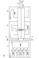
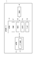
- FIG. 1 is a block diagram schematically showing a configuration example of an information processing system according to the first embodiment of the present invention.
- FIG. 2 is a schematic diagram schematically showing a first configuration example of the suction device according to the first embodiment of the present invention.
- FIG. 3 is a schematic diagram schematically showing a second configuration example of the suction device according to the first embodiment of the present invention.
- FIG. 4 is a block diagram schematically showing a configuration example of an information processing server according to the first embodiment of the present invention.
- FIG. 5 is a flowchart showing a processing example by the information processing server according to the first embodiment of the present invention.
- FIG. 6 is a block diagram schematically showing a configuration example of an information processing server according to a second embodiment of the present invention.
- FIG. 1 is a block diagram schematically showing a configuration example of an information processing system according to the first embodiment of the present invention.
- FIG. 2 is a schematic diagram schematically showing a first configuration example of the suction device according to the first embodiment of the
- FIG. 7 is a block diagram schematically showing a configuration example of a user terminal according to a second embodiment of the present invention.
- FIG. 8 is a flowchart showing a processing example by the information processing server according to the second embodiment of the present invention.
- FIG. 9 is a flowchart showing a processing example by the user terminal according to the second embodiment of the present invention.
- FIG. 1 is a schematic configuration diagram of an information processing system according to the first embodiment of the present invention.
- the information processing system 10 is exemplified by n units (n is an arbitrary integer value of 1 or more) of suction devices 1a to 1n and n units of suction devices 1a to 1n, respectively. It includes n user terminals (n is an arbitrary integer value of 1 or more) to be connected, and an information processing server 3 configured to be able to communicate with the user terminals 2a to 2n via a network N. It is composed.
- n suction devices are described without distinction, the reference numerals are partially omitted and the term "suction device 1" is simply referred to.
- n user terminals when the n user terminals are described without distinction, the reference numerals are partially omitted and the term “user terminals 2” is simply referred to.
- Those having the same alphabetic code attached to the end of each of the suction device 1 and the user terminal 2 are assumed to be possessed by the same user.
- the suction device 1a and the user terminal 2a are possessed by the same user.
- the information processing system 10 is a so-called client / server system.
- the information processing system 10 is realized by the n user terminals 2 which are clients and the information processing server 3 communicating with each other via the network N.
- the network N is realized by, for example, a network such as the Internet or a mobile phone network, a LAN (Local Area Network), or a network combining these.
- the suction device 1 is an electronic device that produces a substance that is sucked by the user.
- the suction device 1 corresponds to a suction tool or a flavor suction tool.
- a configuration example of the suction device that can be the suction device 1 will be described later.
- the user terminal 2 is a portable electronic device having a communication function.
- the user terminal 2 is a smartphone, a tablet terminal, or the like.
- the information processing server 3 is a computer having an information processing function.
- the information processing server 3 is realized by, for example, one or a plurality (at least one) of server devices. A configuration example of the information processing server 3 will be described later.
- the information processing server 3 is an example of an information processing device.
- the suction device 1 and the user terminal 2 are related to each other, and data can be transmitted and received by both parties by executing short-range wireless communication such as Bluetooth (registered trademark) or BLE (Bluetooth Low Energy) communication. It becomes.
- the transmission and reception of data between the suction device 1 and the user terminal 2 is not limited to BLE communication, and for example, Wi-Fi (registered trademark), LPWAN (Low Power Wide Area Network), NFC (Near Field Communication), etc. It may be executed by any communication.
- the transmission / reception of data between the suction device 1 and the user terminal 2 is not necessarily limited to wireless communication, and may be wired communication such as USB (Universal Serial Bus), Mini USB, Micro USB, and Lightning.
- the suction device is a device that produces a substance that is sucked by the user.
- the substance produced by the suction device will be described as being an aerosol.
- the substance produced by the suction device may be a gas.
- FIG. 2 is a schematic diagram schematically showing a first configuration example of a suction device.
- the suction device 100A includes a power supply unit 110, a cartridge 120, and a flavoring cartridge 130.
- the power supply unit 110 includes a power supply unit 111A, a sensor unit 112A, a notification unit 113A, a storage unit 114A, a communication unit 115A, and a control unit 116A.
- the cartridge 120 includes a heating unit 121A, a liquid guiding unit 122, and a liquid storage unit 123.
- the flavoring cartridge 130 includes a flavor source 131 and a mouthpiece 124.
- An air flow path 180 is formed in the cartridge 120 and the flavoring cartridge 130.
- the power supply unit 111A stores electric power. Then, the power supply unit 111A supplies electric power to each component of the suction device 100A based on the control by the control unit 116A.
- the power supply unit 111A may be composed of, for example, a rechargeable battery such as a lithium ion secondary battery.
- the sensor unit 112A acquires various information about the suction device 100A.
- the sensor unit 112A is composed of a pressure sensor such as a microphone capacitor, a flow rate sensor, a temperature sensor, or the like, and acquires a value associated with suction by the user.
- the sensor unit 112A is configured by an input device such as a button or a switch that receives input of information from the user.
- the notification unit 113A notifies the user of the information.
- the notification unit 113A is composed of, for example, a light emitting device that emits light, a display device that displays an image, a sound output device that outputs sound, a vibrating vibration device, and the like.
- the storage unit 114A stores various information for the operation of the suction device 100A.
- the storage unit 114A is composed of a non-volatile storage medium such as a flash memory.
- the storage unit 114A may store the registration code. Further, the storage unit 114A may store the device ID. The registration code and device ID will be described later.
- the communication unit 115A is a communication interface capable of performing communication conforming to any wired or wireless communication standard.
- a communication standard for example, Wi-Fi (registered trademark), Bluetooth (registered trademark), or the like can be adopted.
- the control unit 116A functions as an arithmetic processing device and a control device, and controls the overall operation in the suction device 100A according to various programs.
- the control unit 116A is realized by, for example, an electronic circuit such as a CPU (Central Processing Unit) and a microprocessor.
- the liquid storage unit 123 stores the aerosol source.
- the atomization of the aerosol source produces an aerosol.
- Aerosol sources are, for example, polyhydric alcohols such as glycerin and propylene glycol, and liquids such as water. Aerosol sources may contain tobacco-derived or non-tobacco-derived flavor components.
- the suction device 100A is a medical inhaler such as a nebulizer
- the aerosol source may include a drug.
- the liquid guiding unit 122 guides and holds the aerosol source, which is the liquid stored in the liquid storage unit 123, from the liquid storage unit 123.
- the liquid guiding portion 122 is a wick formed by twisting a fiber material such as glass fiber or a porous material such as a porous ceramic. In that case, the aerosol source stored in the liquid storage unit 123 is induced by the capillary effect of the wick.
- the heating unit 121A heats the aerosol source to atomize the aerosol source and generate an aerosol.
- the heating unit 121A is configured as a coil and is wound around the liquid induction unit 122.
- the heating unit 121A generates heat, the aerosol source held in the liquid induction unit 122 is heated and atomized to generate an aerosol.
- the heating unit 121A generates heat when power is supplied from the power supply unit 111A.
- power may be supplied when the sensor unit 112A detects that the user has started suction and / or that predetermined information has been input. Then, when it is detected by the sensor unit 112A that the user has finished the suction and / or that the predetermined information has been input, the power supply may be stopped.
- the flavor source 131 is a component for imparting a flavor component to the aerosol.
- the flavor source 131 may contain a tobacco-derived or non-tobacco-derived flavor component.
- the air flow path 180 is a flow path of air sucked by the user.
- the air flow path 180 has a tubular structure having an air inflow hole 181 which is an inlet of air into the air flow path 180 and an air outflow hole 182 which is an outlet of air from the air flow path 180 at both ends.
- the liquid guiding portion 122 is arranged on the upstream side (the side close to the air inflow hole 181), and the flavor source 131 is arranged on the downstream side (the side close to the air outflow hole 182).
- the air flowing in from the air inflow hole 181 due to the suction by the user is mixed with the aerosol generated by the heating unit 121A, and is transported to the air outflow hole 182 through the flavor source 131 as shown by the arrow 190.
- the flavor component contained in the flavor source 131 is imparted to the aerosol.
- the mouthpiece 124 is a member that can be held by the user during suction.
- An air outflow hole 182 is arranged in the mouthpiece 124. The user can take in the mixed fluid of aerosol and air into the oral cavity by holding and sucking the mouthpiece 124.
- suction device 100A has been described above.
- the configuration of the suction device 100A is not limited to the above, and various configurations exemplified below can be adopted.
- the suction device 100A does not have to include the flavoring cartridge 130.
- the cartridge 120 is provided with the mouthpiece 124.
- the suction device 100A may include a plurality of types of aerosol sources.
- a plurality of types of aerosols generated from a plurality of types of aerosol sources may be mixed in the air flow path 180 to cause a chemical reaction, whereby another type of aerosol may be produced.
- the means for atomizing the aerosol source is not limited to heating by the heating unit 121A.
- the means for atomizing the aerosol source may be oscillating atomization or induction heating.
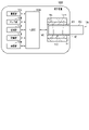
- FIG. 3 is a schematic diagram schematically showing a second configuration example of the suction device.
- the suction device 100B includes a power supply unit 111B, a sensor unit 112B, a notification unit 113B, a storage unit 114B, a communication unit 115B, a control unit 116B, a heating unit 121B, a holding unit 140, and a holding unit 140. Includes insulation 144.
- Each of the power supply unit 111B, the sensor unit 112B, the notification unit 113B, the storage unit 114B, the communication unit 115B, and the control unit 116B is substantially the same as the corresponding components included in the suction device 100A according to the first configuration example. Is.
- the power supply unit 111A and the power supply unit 111B are described as the power supply unit 111 when the two are described without distinction.
- the sensor unit 112A and the sensor unit 112B are the sensor unit 112
- the notification unit 113A and the notification unit 113B are the notification unit 113
- the storage unit 114A and the storage unit 114B are the storage unit 114
- the communication unit 115A and the communication unit 115B are.
- the communication unit 115, the control unit 116A and the control unit 116B are described as the control unit 116
- the heating unit 121A and the heating unit 121B are described as the heating unit 121.
- the holding portion 140 has an internal space 141, and holds the stick-type base material 150 while accommodating a part of the stick-type base material 150 in the internal space 141.
- the holding portion 140 has an opening 142 that communicates the internal space 141 to the outside, and holds the stick-type base material 150 inserted into the internal space 141 from the opening 142.
- the holding portion 140 is a tubular body having an opening 142 and a bottom portion 143 as a bottom surface, and defines a columnar internal space 141.
- the holding portion 140 also has a function of defining a flow path of air supplied to the stick-type base material 150.
- An air inflow hole which is an inlet for air to such a flow path, is arranged, for example, at the bottom 143.
- the air outflow hole which is an outlet for air from such a flow path, is an opening 142.
- the stick-type base material 150 includes a base material portion 151 and a mouthpiece portion 152.
- the base material portion 151 contains an aerosol source.
- the aerosol source is not limited to a liquid, but may be a solid.
- the heating unit 121B has the same configuration as the heating unit 121A according to the first configuration example. However, in the example shown in FIG. 3, the heating unit 121B is formed in a film shape and is arranged so as to cover the outer periphery of the holding unit 140. Then, when the heating unit 121B generates heat, the base material portion 151 of the stick-type base material 150 is heated from the outer periphery to generate an aerosol.
- the heat insulating portion 144 prevents heat transfer from the heating portion 121B to other components.
- the heat insulating portion 144 is made of a vacuum heat insulating material, an airgel heat insulating material, or the like.
- suction device 100B has been described above.
- the configuration of the suction device 100B is not limited to the above, and various configurations exemplified below can be adopted.
- the heating portion 121B may be configured in a blade shape and may be arranged so as to project from the bottom portion 143 of the holding portion 140 to the internal space 141. In that case, the blade-shaped heating portion 121B is inserted into the base material portion 151 of the stick-type base material 150, and the base material portion 151 of the stick-type base material 150 is heated from the inside. As another example, the heating portion 121B may be arranged so as to cover the bottom portion 143 of the holding portion 140. Further, the heating unit 121B is a combination of two or more of a first heating unit that covers the outer periphery of the holding unit 140, a blade-shaped second heating unit, and a third heating unit that covers the bottom portion 143 of the holding unit 140. It may be configured as.
- the holding portion 140 may include an opening / closing mechanism such as a hinge that opens / closes a part of the outer shell forming the internal space 141. Then, the holding portion 140 may sandwich the stick-type base material 150 inserted in the internal space 141 by opening and closing the outer shell.
- the heating unit 121B may be provided at the holding portion of the holding unit 140 and may be heated while pressing the stick-type base material 150.
- the means for atomizing the aerosol source is not limited to heating by the heating unit 121B.
- the means for atomizing the aerosol source may be induction heating.
- the suction device 100B may further include a heating unit 121A, a liquid induction unit 122, a liquid storage unit 123, and an air flow path 180 according to the first configuration example, and the air flow path 180 air outflow hole 182. May also serve as an air inflow hole to the internal space 141.
- the mixed fluid of the aerosol and air generated by the heating unit 121A flows into the internal space 141, is further mixed with the aerosol generated by the heating unit 121B, and reaches the user's oral cavity.
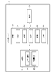
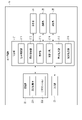
- FIG. 4 is a block diagram schematically showing a configuration example of an information processing server according to the first embodiment of the present invention.
- the information processing server 3 includes a control unit 31, a storage unit 32, and a communication unit 33. The parts are connected to each other via a bus line.
- the control unit 31 controls the operation of the entire information processing server 3 according to the program stored in the storage unit 32.
- the control unit 31 is composed of an electronic circuit such as a processor.
- the processor is a CPU or the like.
- the control unit 31 realizes each unit described later by executing the program stored in the storage unit 32, and executes various operations.
- the storage unit 32 is composed of a main storage device and an auxiliary storage device.
- the main storage consists of volatile memory that provides a working area for the processor.
- the main storage device is composed of a RAM (Random Access Memory) or the like.
- the auxiliary storage device is composed of a non-volatile memory that stores various information and programs for the operation of the information processing server 3.
- the auxiliary storage device is composed of an HDD (Hard Disk Drive), an SSD (Solid State Drive), or the like.
- the storage unit 32 stores in the control unit 31 a program for realizing each unit described later.
- the storage unit 32 stores the user information DB 321 and the setting information DB 322.
- the user information DB 321 is a database that stores user information that is information unique to the user who owns the user terminal 2.
- the user information DB 321 includes a user information record composed of at least one of a registration code, a user ID, a device ID, user data, and a registration flag.
- the user ID is an identifier uniquely assigned to the user.
- the user ID is an example of user identification information.
- the user ID is used for user registration by the information processing server 3.
- the user ID is input by the user from an input unit (not shown) of the user terminal 2 and is set at the time of user registration.
- the user ID is transmitted from the user terminal 2 to the information processing server 3 at the time of user registration, and is stored in the user information DB 321.
- the registration code is information used for registering the suction device 1 in the information processing server 3.
- the registration code is composed of, for example, a combination of a predetermined number of alphanumerical characters, and is provided for each suction device 1.
- the registration code is transmitted from the suction device 1 to the information processing server 3 via the user terminal 2 and stored in the user information DB 321.
- the device ID is the device ID of the suction device 1 associated with the user terminal 2.
- the device ID of the suction device 1 is identification information for identifying each suction device 1.
- the device ID is, for example, a serial number.
- the device ID is an example of the identification information of the suction device 1.
- the device ID is transmitted from the user terminal 2 to the information processing server 3 and stored in the user information DB 321.
- User data is data that identifies the user.
- the user data is used for user registration by the information processing server 3.
- the user data includes at least one of information indicating a user name, a user's gender, age, identity verification information, and the like.
- the identity verification information is, for example, an image of a public identification card such as a driver's license or my number card, or an electronic certificate for identity verification read from a my number card or the like.
- the identity verification information may be, for example, any information that can confirm the age of the user.
- User data is input from an input unit (not shown) of the user terminal 2 at the time of user registration or subsequent update of user registration by the user.
- the user data is transmitted from the user terminal 2 to the information processing server 3 and stored in the user information DB 321.
- the registration flag is information indicating that the user registration is completed in the information processing server 3. Adding the registration flag is to make the user available to various services provided by the information processing server 3.
- User registration is, for example, account registration for authenticating a user.
- the user information may be updated as appropriate.
- the user information may include information other than the above.
- the setting information DB 322 is a database that records information for setting a plurality of types of suction devices 1.
- the information for setting the suction device 1 is also hereinafter referred to as "setting information".
- the setting information is information that differs depending on the type of the suction device 1.
- the setting information is guide information indicating a procedure for setting the suction device 1 performed by the user when the suction device 1 is used for the first time.
- the setting information DB 322 stores the setting information in association with the type information of the suction device 1.
- the type information is information such as the model number and version information of the suction device 1.
- the type information of the suction device 1 may be a part of the device ID of the suction device 1, or may be information associated with the registration code of the suction device 1 or the device ID by a database (not shown).
- the data of the setting information DB 322 may be stored in the storage unit 32 in advance, or may be downloaded from a server (not shown) to the information processing server 3 via the network N.
- the setting information DB 322 may be updated as appropriate.
- the communication unit 33 is composed of one or more communication interfaces capable of performing communication conforming to any wireless communication standard.
- the communication unit 33 includes one or more communication interfaces capable of communicating between the information processing server 3 and the user terminal 2 via the network N as described above.
- the hardware configuration of the information processing server 3 is not limited to the above configuration.
- the information processing server 3 makes it possible to omit or change the above-mentioned components and add new components as appropriate.
- control unit 31 realizes an acquisition unit 311, a specific unit 312, a determination unit 313, an execution unit 314, and an output unit 315. It should be noted that each unit realized by the control unit 31 can also be said to be each function. The fact that each part is realized in the control unit 31 can also mean that each part is realized in the processor.
- the acquisition unit 311 acquires the registration code from the user terminal 2 connected to the suction device 1 in response to the activation of the suction device 1, for example, via the communication unit 33. Further, the acquisition unit 311 may acquire the device ID of the suction device 1 from the user terminal 2 connected to the suction device 1 in response to the activation of the suction device 1 via the communication unit 33. Further, the acquisition unit 311 acquires information used for user registration from the user terminal 2 via the communication unit 33. The information used for user registration is also hereinafter referred to as "user registration information".
- the user registration information includes a user ID. At the time of user registration or update of user registration, the user registration information includes user data in addition to the user ID. If the user has completed the user registration in the past and does not update the user registration, the user registration information may not include the user data.
- the user registration is to register the user registration information of the user who uses the suction device 1 in the information processing server 3.
- the user registration may be the registration of the suction device 1, that is, the registration of the suction device 1 (so-called device registration). Further, the user registration may be to register a user who uses the suction device 1.
- the user registration may be completed when either the registration of the suction device 1 (so-called device registration) or the user registration is completed. Further, the user registration may be completed when both the registration of the suction device 1 (so-called device registration) and the user registration are completed.
- the user registration information includes at least one of a registration code, a device ID, and a user ID.
- the user registration information may include only one of a registration code, a device ID, and a user ID.
- the user registration information may include a plurality of information among the registration code, the device ID, and the user ID.
- the identification unit 312 specifies the setting information corresponding to the registration code or device ID acquired by the acquisition unit 311.
- the determination unit 313 determines whether or not the user registration of the user is completed based on the user registration information acquired by the acquisition unit 311. The determination unit 313 determines whether or not the registration of the suction device 1 (so-called device registration) has been completed based on the registration code or the device ID in the user registration information acquired by the acquisition unit 311. Further, the determination unit 313 may determine whether or not the user registration is completed based on the user ID included in the user registration information acquired by the acquisition unit 311. The determination unit 313 may determine whether or not both the registration of the suction device 1 (so-called device registration) and the registration of the user have been completed.
- the execution unit 314 executes the user registration of the user based on the user registration information acquired by the acquisition unit 311 in response to the determination by the determination unit 313 that the user registration of the user has not been completed.
- the output unit 315 outputs the setting information specified by the specific unit 312 to the user terminal 2 via the communication unit 33.
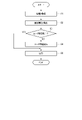
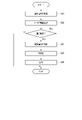
- FIG. 5 is a flowchart showing a processing example by the information processing server according to the first embodiment of the present invention.
- the processing procedure described below is only an example, and each processing may be changed as much as possible. Further, with respect to the processing procedure described below, steps can be omitted, replaced, and added as appropriate according to the embodiment.
- the user A, the suction device 1a, and the user terminal 2a will be described below as an example.
- User A is a user who possesses the suction device 1a and the user terminal 2a.
- the acquisition unit 311 acquires the registration code or device ID of the suction device 1a from the user terminal 2a connected to the suction device 1a in response to the activation of the suction device 1a (step S1).
- step S1 for example, the acquisition unit 311 acquires the user registration information of the user A from the user terminal 2a together with the registration code or the device ID of the suction device 1a via the communication unit 33.
- the suction device 1a transmits the registration code or device ID of the suction device 1a to the user terminal 2a in response to the activation such as the initial activation.
- the user terminal 2a becomes able to communicate with the suction device 1a in response to the activation of the suction device 1a, and receives the registration code or device ID of the suction device 1a transmitted from the suction device 1a.
- the user terminal 2a responds to the reception of the registration code or device ID of the suction device 1a from the suction device 1a, and the user registration information of the user A together with the registration code or device ID of the suction device 1a via the network N. Is transmitted to the information processing server 3.
- the user registration information is information input by the user A from an input unit (not shown) of the user terminal 2a.
- the user registration information includes a user ID.
- the user registration information may include user data in addition to the user ID.
- the acquisition unit 311 may acquire both the registration code of the suction device 1a and the device ID.
- the acquisition unit 311 adds the acquired registration code or device ID to the user information DB 321 one by one in association with the user ID that already exists in the user information DB 321.
- the acquisition unit 311 adds the user data associated with the user ID to the user information DB 321 so as to update the user data.
- the user registration may be updated.
- the registration flag is added in association with the user ID of the user A in the user information DB 321.
- the acquisition unit 311 adds a user information record associated with the acquired registration code or device ID and the user ID and user data included in the acquired user registration information to the user information DB 321. Since the user registration of the user A has not been completed, the registration flag is not added in association with the user ID of the user A in the user information DB 321.
- the identification unit 312 specifies the setting information corresponding to the registration code or device ID acquired by the acquisition unit 311 (step S2).
- step S2 for example, the specific unit 312 acquires the registration code or device ID of the suction device 1a acquired by the acquisition unit 311 from the user information DB 321.
- the specific unit 312 acquires the type information of the suction device 1a based on a part of the registration code or the device ID of the suction device 1a or a database (not shown).
- the specifying unit 312 specifies the setting information associated with the type information of the suction device 1a based on the setting information DB 322.
- the determination unit 313 determines whether or not the user registration of the user A is completed based on the user registration information (step S3).
- the determination unit 313 acquires the user ID acquired by the acquisition unit 311 from the user information DB 321.
- the determination unit 313 determines whether or not the user registration is completed based on the registration flag associated with the user ID.
- the determination unit 313 may collate the user ID with a database (not shown) that manages the information of the registered user to determine whether or not the user registration is completed.
- "completion" of user registration includes a state in which user registration has already been performed, that is, a state in which user registration has been completed.
- step S3 determines that the user registration of the user A has been completed (step S3: YES)
- step S5 determines that the user registration of the user A has not been completed
- step S3 determines that the user registration of the user A has not been completed
- the execution unit 314 executes the user registration of the user A based on the user registration information in response to the determination by the determination unit 313 that the user registration of the user A has not been completed (step S4).
- step S4 for example, the execution unit 314 acquires the user data included in the user registration information acquired by the acquisition unit 311 from the user information DB 321.
- the execution unit 314 executes the user registration of the user A based on the user data.
- the execution unit 314 adds a registration flag in the user information DB 321 in association with the user ID of the user A.
- the execution of user registration by the execution unit 314 corresponds to the state in which the user has already been registered. According to this example, the information processing server 3 can execute user registration without newly acquiring user registration information from user A.
- the execution unit 314 executes the user registration of the user A based on the identity verification information of the user A.
- the execution unit 314 executes the user registration of the user A.
- the execution unit 314 does not execute the user registration of the user A.
- the information processing server 3 can confirm the age of the user A when executing the user registration. Therefore, the information processing server 3 can encourage the use of the suction device 1a in accordance with the age regulation.
- the output unit 315 outputs the setting information specified by the specific unit 312 to the user terminal 2a (step S5).
- step S5 for example, the output unit 315 outputs the setting information about the suction device 1a specified by the specific unit 312 to the user terminal 2a via the communication unit 33.
- "outputting" by the output unit 315 includes “transmitting" data.
- the output unit 315 outputs the setting information to the user terminal 2a according to the user registration state of the user A based on the user registration information.
- the user registration status is a user registration status.
- the output unit 315 outputs the setting information of the suction device 1a to the user terminal 2a in response to the determination by the determination unit 313 that the user registration of the user A is completed.
- the fact that the determination unit 313 determines that the user registration of the user A has been completed corresponds to the user-registered state of the user A.
- the output unit 315 outputs the setting information of the suction device 1a to the user terminal 2a in response to the user registration of the user A being executed by the execution unit 314.
- the fact that the user registration of the user A is executed by the execution unit 314 corresponds to the user-registered state of the user A.
- the information processing server 3 can present the setting information only to the user who has completed the user registration. Therefore, the information processing server 3 can suppress the use of a user whose user registration has not been completed.
- steps S3 to S4 may be omitted. That is, in step S1, the acquisition unit 311 acquires the registration code or device ID of the suction device 1a from the user terminal 2a via the communication unit 33, but does not have to acquire the user registration information. The information processing server 3 does not determine the completion of user registration and execute user registration.
- the output unit 315 may output the setting information specified by the specific unit 312 to the user terminal 2a in response to the acquisition of the identification information of the suction device 1a by the acquisition unit 311.
- the information processing server 3 indicates to the user terminal 2 that the user registration cannot be completed when the user registration is not completed for a predetermined reason in the user registration execution in step S4. May be output.
- the output unit 315 outputs the error information
- the output unit 315 does not output the setting information.
- the predetermined reason is, for example, that the user data does not include the identity verification information. Further, the predetermined reason is that, for example, the age of the user of the identity verification information included in the user data has not reached the predetermined age. Further, for example, the acquired registration code or device ID is already used for user registration of another user.
- the predetermined reason is not limited to these examples, and may be any reason as long as the user registration cannot be executed.
- the error signal may include information about a given reason.
- the user terminal 2a can acquire the setting information corresponding to the suction device 1a used by the user A from the outside. Therefore, even if the setting information is not stored in advance in the suction device 1a or the user terminal 2a, the information processing server 3 can present the setting information to the user A. In addition, the memory resources of the suction device 1a or the user terminal 2a can be saved. Further, the information processing server 3 can present the setting information corresponding to the suction device 1a necessary for the user A at a necessary timing without requiring the user A to search for the setting information.
- the information processing device may be realized by one device as described by taking the information processing server 3 as an example, or may be realized by a plurality of devices having distributed functions.
- the second embodiment will be described with reference to the drawings.
- the setting information is displayed on the user terminal based on the identification information of the suction device.
- the user terminal is an example of an information processing terminal.
- the same reference numerals are given to the same configurations as those of the first embodiment, and the description thereof will be omitted.
- the second embodiment mainly the parts different from the first embodiment will be described.
- FIG. 6 is a block diagram schematically showing a configuration example of an information processing server according to a second embodiment of the present invention.
- the storage unit 32 stores in the control unit 31 a program for realizing each unit described later.
- the storage unit 32 stores the user information DB 321. Unlike the first embodiment, the storage unit 32 does not store the setting information DB 322.
- the hardware configuration of the information processing server 3 is not limited to the above configuration.
- the information processing server 3 makes it possible to omit or change the above-mentioned components and add new components as appropriate.
- control unit 31 realizes an acquisition unit 311, a determination unit 313, an execution unit 314, and an output unit 315. Unlike the first embodiment, the control unit 31 does not have the specific unit 312. It should be noted that each unit realized by the control unit 31 can also be said to be each function. The fact that each part is realized in the control unit 31 can also mean that each part is realized in the processor.
- the acquisition unit 311 acquires the user registration information of the user from the user terminal 2 via the communication unit 33.
- the determination unit 313 determines whether or not the user registration of the user is completed based on the user registration information acquired by the acquisition unit 311. The determination unit 313 determines whether or not the registration of the suction device 1 (so-called device registration) has been completed based on the registration code or the device ID in the user registration information acquired by the acquisition unit 311. Further, the determination unit 313 may determine whether or not the user registration is completed based on the user ID included in the user registration information acquired by the acquisition unit 311. The determination unit 313 may determine whether or not both the registration of the suction device 1 (so-called device registration) and the registration of the user have been completed.
- the execution unit 314 executes the user registration of the user based on the user registration information in response to the determination by the determination unit 313 that the user registration of the user has not been completed.
- the output unit 315 outputs a notification to the user terminal 2 via the communication unit 33.
- the notification is a notification regarding the completion of user registration of the user.
- the notification indicates that the user has already registered as a user. Registered as a user corresponds to the fact that the user registration of the user has been completed or that the user registration of the user has been executed.
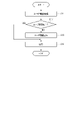
- FIG. 7 is a block diagram schematically showing a configuration example of a user terminal according to a second embodiment of the present invention.
- the user terminal 2a includes a control unit 21, a storage unit 22, an input unit 23, a display unit 24, a communication unit 25, and a detection unit 26.
- the parts are connected to each other via a bus line.
- the control unit 21 controls the operation of the entire user terminal 2a according to the program stored in the storage unit 22.
- the control unit 21 is composed of an electronic circuit such as a processor.
- the processor is a CPU or the like.
- the storage unit 22 is composed of a main storage device and an auxiliary storage device, similarly to the storage unit 32 described above.
- the storage unit 22 stores in the control unit 21 a program for realizing each unit described later.
- the storage unit 22 stores the setting information DB 221 and the application 222.
- the setting information DB 221 is a database that stores the setting information of the suction device 1 like the setting information DB 322 described above.
- the data of the setting information DB 221 may be downloaded from the information processing server 3 via the network N, or may be downloaded from a server (not shown) via the network N to the user terminal 2a.
- the setting information DB 322 may be updated as appropriate.
- the data of the setting information DB 322 may be downloaded in association with the download of the application 222.
- the application 222 is an application program that provides various functions to the user terminal 2a.
- the application 222 may be downloaded from the information processing server 3 via the network N, or may be downloaded from a server (not shown) via the network N to the user terminal 2a.
- Application 222 may be updated as appropriate.
- the application 222 provides a function of displaying the setting information stored in the setting information DB 221 on the display unit 24.
- the application 222 displays the setting information of a plurality of types of suction devices 1 on the display unit 24.
- the application 222 provides a function for enabling the display of the setting information stored in the setting information DB 221.
- the input unit 23 accepts instructions or captures data based on the operation by the user.
- the input unit 23 is composed of a keyboard, a touch pad, a camera, or the like.
- the display unit 24 displays various screens.
- the display unit 24 is composed of a liquid crystal display or the like.
- the communication unit 25 is composed of one or more communication interfaces capable of performing communication conforming to any wired or wireless communication standard.
- the communication unit 25 includes one or more communication interfaces capable of communicating between the user terminal 2a and the suction device 1a as described above.
- the communication unit 25 includes one or more communication interfaces capable of communicating between the user terminal 2a and the information processing server 3 via the network N as described above.
- the detection unit 26 is composed of sensors that detect various types of information.
- the detection unit 26 includes a sensor that detects the position information of the user terminal 2a.
- the position information is information indicating latitude and longitude.
- the sensor that detects the position information is a GPS sensor.
- the hardware configuration of the user terminal 2a is not limited to the above configuration.
- the user terminal 2a makes it possible to omit or change the above-mentioned components and add new components as appropriate.
- a configuration example of the user terminal 2a has been described, but since the configuration of the user terminal 2 other than the user terminal 2a is the same as the configuration of the user terminal 2a, the description thereof will be omitted.
- control unit 21 realizes a first acquisition unit 211, a second acquisition unit 212, a specific unit 213, an activation unit 214, a first output unit 215, and a second output unit 216. It should be noted that each unit realized by the control unit 21 can also be said to be each function. The fact that each part is realized in the control unit 21 can also mean that each part is realized in the processor.
- the first acquisition unit 211 acquires the registration code or device ID of the suction device 1 from the suction device 1 in response to the activation of the suction device 1 via the communication unit 25.
- the first acquisition unit 211 may acquire both the registration code and the device ID of the suction device 1 from the suction device 1.
- the second acquisition unit 212 acquires the notification from the information processing server 3 via the communication unit 25.
- the identification unit 213 specifies the setting information corresponding to the registration code or the device ID in response to the acquisition of the notification by the second acquisition unit 212.
- the activation unit 214 enables the display of the setting information specified by the specific unit 213 based on the notification acquired by the second acquisition unit 212.
- the first output unit 215 outputs the user registration information to the information processing server 3 via the communication unit 25 in response to the acquisition of the registration code or the device ID by the first acquisition unit 211.
- the second output unit 216 outputs the setting information specified by the specific unit 213 to the display unit 24.
- the display unit 24 displays the setting information specified by the specific unit 213.
- FIG. 8 is a flowchart showing a processing example by the information processing server according to the second embodiment of the present invention.
- the processing procedure described below is only an example, and each processing may be changed as much as possible. Further, with respect to the processing procedure described below, steps can be omitted, replaced, and added as appropriate according to the embodiment.
- the user A, the suction device 1a, and the user terminal 2a will be described below as an example.
- User A is a user who possesses the suction device 1a and the user terminal 2a.
- the acquisition unit 311 acquires the user registration information of the user A (step S11).
- step S11 for example, the acquisition unit 311 acquires the user registration information of the user A from the user terminal 2a via the communication unit 33.
- the user registration information of the user A is transmitted from the user terminal 2a connected to the suction device 1a to the information processing server 3 in response to the activation of the suction device 1a.
- the user registration information includes a user ID.
- the user registration information includes user data in addition to the user ID.
- the acquisition unit 311 adds the acquired user registration information to the user information DB 321 as in the first embodiment.
- the determination unit 313 determines whether or not the user registration of the user A is completed based on the user registration information (step S12). In step S12, for example, the determination unit 313 determines whether or not the user registration of the user A has been completed, as in the first embodiment.
- step S12 determines that the user registration of the user A has been completed (step S12: YES)
- step S12 determines that the user registration of the user A has been completed (step S12: YES)
- step S12 determines that the user registration of the user A has not been completed (step S12: NO)
- step S12 determines that the user registration of the user A has not been completed (step S12: NO)
- the execution unit 314 executes the user registration of the user A in response to the determination by the determination unit 313 that the user registration of the user A has not been completed (step S13).
- step S13 for example, the execution unit 314 executes the user registration of the user A as in the first embodiment.
- the information processing server 3 can execute user registration without newly acquiring user registration information from user A.
- the execution unit 314 executes the user registration of the user A based on the identity verification information of the user A.
- the information processing server 3 can confirm the age of the user when executing the user registration. Therefore, the information processing server 3 can encourage the use of the suction device 1a in accordance with the age regulation.
- the output unit 315 outputs a notification to the user terminal 2a (step S14).
- step S14 for example, the output unit 315 outputs a notification regarding the completion of user registration of the user A to the user terminal 2a via the communication unit 33.
- the output unit 315 sends a notification to the user terminal 2a indicating that the user registration of the user A is completed in response to the determination by the determination unit 313 that the user registration of the user A is completed.
- the output unit 315 outputs a notification indicating that the user registration of the user A has been executed to the user terminal 2a in response to the execution of the user registration of the user A by the execution unit 314. Note that "outputting" to the user terminal 2a includes “transmitting" data to the user terminal 2a.
- the information processing server 3 outputs an error signal indicating that the user registration cannot be performed to the user terminal 2 when the user registration is not completed for a predetermined reason in the user registration execution. You may.
- the error signal may include information about a given reason.
- FIG. 9 is a flowchart showing a processing example by the user terminal according to the second embodiment of the present invention.
- the processing procedure described below is only an example, and each processing may be changed as much as possible. Further, with respect to the processing procedure described below, steps can be omitted, replaced, and added as appropriate according to the embodiment.
- the user A, the suction device 1a, and the user terminal 2a will be described below as an example.
- User A is a user who possesses the suction device 1a and the user terminal 2a.
- the first acquisition unit 211 acquires the registration code or device ID of the suction device 1a from the suction device 1a in response to the activation of the suction device 1a via the communication unit 25 (step S21).
- step S21 for example, the first acquisition unit 211 receives the registration code or device ID of the suction device 1a from the suction device 1a in response to the initial activation of the suction device 1a via the communication unit 25.
- the user terminal 2a becomes communicable with the suction device 1a in response to the activation of the suction device 1a, and receives the registration code or device ID of the suction device 1a transmitted from the suction device 1a.
- the first acquisition unit 211 stores the acquired registration code or device ID of the suction device 1a in the storage unit 22.
- the acquired registration code or device ID is stored in the storage unit 22 one by one.
- the first acquisition unit 211 may acquire both the registration code of the suction device 1a and the device ID from the suction device 1a in response to the activation of the suction device 1a.
- the first output unit 215 outputs the user registration information to the information processing server 3 via the communication unit 25 in response to the acquisition of the registration code or the device ID by the first acquisition unit 211 (step S22). .. In step S22, for example, the first output unit 215 outputs the user registration information input by the user A via the input unit 23 to the information processing server 3.
- the user registration information includes a user ID.
- the user registration information includes user data in addition to the user ID.
- the user registration information input via the input unit 23 is stored in the storage unit 22 one by one.
- the user registration information may be updated as appropriate by the input of the user A.
- the first output unit 215 acquires the user registration information from the storage unit 22 in response to the acquisition of the registration code or the device ID by the first acquisition unit 211.
- the first output unit 215 outputs the acquired user registration information to the information processing server 3.
- the second acquisition unit 212 acquires a notification regarding the completion of user registration of user A from the information processing server 3 via the communication unit 25 (step S23).
- step S23 for example, the second acquisition unit 212 acquires a notification regarding the completion of user registration of the user A based on the user registration information output by the first output unit 215. Since the notification regarding the completion of user registration of user A is a response to the user registration information output by the first output unit 215, it is a notification based on the user registration information.
- the second acquisition unit 212 acquires a notification from the information processing server 3 indicating that the user registration of the user A is completed.
- the second acquisition unit 212 acquires a notification from the information processing server 3 indicating that the user registration of the user A has been executed.
- step S23: YES When the second acquisition unit 212 acquires the notification (step S23: YES), the process transitions from step S23 to step S24. If the second acquisition unit 212 does not acquire the notification (step S23: NO), the process ends.
- the identification unit 213 specifies the setting information corresponding to the registration code or the device ID in response to the acquisition of the notification by the second acquisition unit 212 (step S24).
- the specific unit 213 acquires the registration code or device ID of the suction device 1a from the storage unit 22.
- the identification unit 312 specifies the type information of the suction device 1a based on the registration code or the device ID of the suction device 1a.
- the type information may be a part of the registration code or device ID of the suction device 1a, and is associated with the registration code or device ID of the suction device 1a by a database (not shown) stored in the storage unit 22. May be.
- the specifying unit 213 specifies the setting information associated with the type information of the suction device 1a based on the setting information DB 221.
- the activation unit 214 enables the display of the setting information specified by the specific unit 213 based on the notification acquired by the second acquisition unit 212 (step S25).
- step S25 for example, the activation unit 214 enables the display of only the setting information specified by the specific unit 213 among the setting information stored in the setting information DB 221.
- the activation unit 214 maintains the invalidity of the display of the setting information other than the setting information specified by the specific unit 213 among the setting information stored in the setting information DB 221.
- the second output unit 216 outputs the setting information specified by the specific unit 213 to the display unit 24 in response to the activation of the display of the setting information specified by the specific unit 213 by the activation unit 214 (step). S26).
- step S26 for example, the second output unit 216 outputs the setting information of the suction device 1a to the display unit 24.
- the display unit 24 displays the setting information of the suction device 1a.
- the display of the setting information of the suction device 1a is realized by, for example, the display function of the application 222.
- the user terminal 2a can acquire the setting information of the suction device 1a used by the user A from the outside. Therefore, even if the setting information is not stored in advance in the suction device 1a, the user terminal 2a can present the setting information to the user A. Moreover, the memory resource of the suction device 1a can be saved. Further, according to this example, the user terminal 2a can enable the display of the setting information only for the user who has completed the user registration. Therefore, the user terminal 2a can suppress the use of a user whose user registration has not been completed.
- step S25 may be omitted in the above processing by the user terminal 2a.
- the display of the setting information stored in the setting information DB 221 is valid regardless of whether or not the notification is acquired by the second acquisition unit 212.
- the second output unit 216 outputs the setting information specified by the specific unit 213 to the display unit 24 based on the notification acquired by the second acquisition unit 212.
- the user terminal 2 may acquire an error signal indicating that the user registration cannot be performed from the information processing server 3 when the user registration is not completed for a predetermined reason in the user registration execution. ..
- the error signal may include information about a given reason.
- the user terminal 2 acquires the error signal, the display of the setting information is not enabled and the setting information is not output to the display unit 24.
- the user terminal 2 may display a predetermined reason included in the acquired error signal on the display unit 24.
- the user terminal 2a can acquire the setting information of the suction device 1a used by the user A from the outside. Therefore, even if the setting information is not stored in advance in the suction device 1a, the user terminal 2a can present the setting information to the user A. Moreover, the memory resource of the suction device 1a can be saved. Further, according to this example, the user terminal 2a can present the setting information only to the user who has completed the user registration. Therefore, the user terminal 2a can suppress the use of a user whose user registration has not been completed. Further, the user terminal 2a can present the setting information corresponding to the suction device 1a necessary for the user A at a necessary timing without requiring the user A to search for the setting information.
- the information processing device may be realized by one device as described by taking the information processing server 3 as an example, or may be realized by a plurality of devices having distributed functions.
- the information processing terminal according to the second embodiment may be realized by one device as described by taking the user terminal 2 as an example, or may be realized by a plurality of devices having distributed functions.
- the program may be transferred in a state stored in the device, or may be transferred in a state not stored in the device. In the latter case, the program may be transferred via the network or may be transferred as recorded on a recording medium.
- the recording medium is a non-temporary tangible medium.
- the recording medium is a computer-readable medium.
- the recording medium may be any medium as long as it can store a program such as a CD-ROM or a memory card and can be read by a computer, and its form is not limited.
- the information processing server 3 outputs the setting information of the suction device 1 to the user terminal 2 of the user who has completed the user registration.
- the first modification is an embodiment in which the information processing server 3 outputs a control signal for enabling the suction device 1 of the user whose user registration has been completed, in addition to outputting the setting information. In the first modification, some or all the functions of the suction device 1 are restricted or invalidated until the user registration is completed.
- the user terminal 2 that has acquired the setting information may output a control signal for enabling the suction device 1 of the user whose user registration has been completed, instead of the information processing server 3.
- the determination unit 313 determines whether or not the user registration of the user is completed based on the user registration information acquired by the acquisition unit 311.
- the output unit 315 can output a control signal for controlling the suction device 1 via the communication unit 33 and the user terminal 2.
- the control signal for controlling the suction device 1 is, for example, a signal for enabling the operation of a part or all of the heating unit 121 of the suction device 1.
- control signal may be, for example, a signal for controlling the notification unit 113 of the suction device 1.
- the control signal is, for example, a signal for changing the color or pattern of light emission.
- the control signal is, for example, a signal for causing the color of the light emitting device to emit light in a predetermined color or a predetermined pattern when the user registration is completed.
- the control signal is, for example, a signal for causing the display device to display predetermined information.
- the control signal is, for example, a signal for displaying information indicating that the user registration is completed on the display device when the user registration is completed.
- the control signal is, for example, a signal for outputting a predetermined sound.
- the control signal is, for example, a signal for causing the sound output device to output a predetermined sound indicating that the user registration is completed when the user registration is completed.
- the control signal is a signal for changing the vibration pattern. The control signal is not limited to these examples.
- the control signal is, for example, a signal for causing the vibration device to output a predetermined vibration indicating that the user registration is completed when the user registration is completed.
- the output unit 315 outputs a notification regarding the completion of user registration to the user terminal 2a, and also outputs a control signal for controlling the suction device 1 via the user terminal 2. For example, when the determination unit 313 determines that the user registration has been completed, the output unit 315 outputs a control signal for controlling the suction device 1. Further, the output unit 315 outputs a control signal for controlling the suction device 1, for example, when the user registration is executed by the execution unit 314. The output unit 315 outputs, for example, a control signal for enabling the operation of a part or all of the heating unit 121 of the suction device 1.
- control unit 21 acquires a control signal for controlling the suction device 1 from the information processing server 3, the control unit 21 outputs a control signal to the suction device 1 via the communication unit 25.
- the control unit 21 outputs, for example, a control signal for enabling the operation of a part or all of the heating unit 121 of the suction device 1 to the suction device 1.
- the display unit 24 may display information indicating the content of control of the suction device 1 based on the control signal. For example, the display unit 24 has acquired a control signal for activating the operation of a part or all of the heating unit 121 of the suction device 1, and the display unit 24 has acquired a part or all of the heating unit 121 of the suction device 1. Information indicating that the operation has been activated may be displayed.
- the control unit 116 controls the operation of a part or all of the heating unit 121 based on the acquisition of the control signal for activating the operation of a part or all of the heating unit 121 of the suction device 1. For example, when all the functions of the heating unit 121 of the suction device 1 are disabled, the control unit 116 has acquired a control signal for enabling the operation of a part or all of the heating unit 121. Based on this, the operation of a part or all of the heating unit 121 is enabled.
- Enabling the operation of a part of the heating unit 121 is, for example, enabling the heating unit 121 to operate according to a part of the plurality of heating profiles when a plurality of heating profiles are stored in the storage unit 114. ..
- the control unit 116 makes the heating unit 121 operable according to some heating profiles based on the acquisition of a control signal indicating that the heating unit 121 can be operated according to some heating profiles.
- the heating profile is information that defines the operation of generating the aerosol (that is, the operation of heating the base material) performed by the suction device 1.
- the suction device 1 produces an aerosol by heating the substrate according to the heating profile.
- the heating profile is, for example, information indicating time-series changes in parameters related to the operation of generating an aerosol performed by the suction device 1.
- An example of the parameter is the temperature of the heating unit 121.
- the control unit 116 controls the temperature of the heating unit 121 so that the temperature similar to the target temperature is realized in the heating unit 121 with the temperature defined in the heating profile as the target temperature.
- the temperature control of the heating unit 121 can be realized by, for example, a known feedback control. Specifically, the control unit 116 supplies the electric power from the power supply unit 111 to the heating unit 121 in the form of a pulse by pulse width modulation (PWM) or pulse frequency modulation (PFM). In that case, the control unit 116 can control the temperature of the heating unit 121 by adjusting the duty ratio of the power pulse.
- PWM pulse width modulation
- PFM pulse frequency modulation
- the control unit 116 may control the electric power supplied to the heating unit 121, for example, the duty ratio described above, based on the difference between the temperature of the heating unit 121 and the target temperature.
- the feedback control may be, for example, PID control (Proportional-Integral-Differential Controller).
- the temperature of the heating unit 121 can be quantified, for example, by measuring or estimating the electric resistance value of the heat generating resistor constituting the heating unit 121. This is because the electric resistance value of the heat generation resistor changes according to the temperature.
- the electric resistance value of the heat-generating resistor can be estimated, for example, by measuring the amount of voltage drop in the heat-generating resistor.
- the amount of voltage drop in the heat-generating resistor can be measured by a voltage sensor that measures the potential difference applied to the heat-generating resistor.
- the temperature of the heating unit 121 can be measured by a temperature sensor installed near the heating unit 121.
- control unit 116 changes the color and pattern of the light emitted from the light emitting device based on the acquisition of the control signal for changing the color and pattern of the light emitted by the light emitting device which is the notification unit 113 of the suction device 1. ..
- the control unit 116 causes the light emitting device to emit light in a predetermined color or a predetermined pattern, for example, based on the acquisition of a control signal for emitting light in a predetermined color or a predetermined pattern indicating that the user registration is completed. ..
- control unit 116 causes the display device to display the predetermined information based on the acquisition of the control signal for displaying the predetermined information on the display device which is the notification unit 113 of the suction device 1.
- the control unit 116 causes the display device to display the information indicating that the user registration is completed, for example, based on the acquisition of the control signal for displaying the predetermined information indicating that the user registration is completed.
- control unit 116 causes the sound output device to output a predetermined sound based on the acquisition of a control signal for causing the sound output device, which is the notification unit 113 of the suction device 1, to output a predetermined sound.
- the control unit 116 causes the sound output device to output a sound indicating that the user registration is completed, for example, based on the acquisition of a control signal for outputting a predetermined sound indicating that the user registration is completed.
- control unit 116 changes the vibration pattern of the vibration device based on the acquisition of the control signal for changing the vibration pattern of the vibration device which is the notification unit 113 of the suction device 1.
- the control unit 116 vibrates the vibrating device with a predetermined vibration, for example, based on the acquisition of a control signal for vibrating with a predetermined vibration indicating that the user registration is completed.
- the suction device 1 can enable a part or all of the functions of the suction device 1 based on the control signal acquired from the information processing server 3 or the user terminal 2. For example, when the user registration is completed, the information processing server 3 or the user terminal 2 transmits a control signal for activating a part or all of the functions of the suction device 1 to the suction device 1, so that the user registration is performed. Upon completion, it becomes possible to activate some or all of the functions of the suction device 1.
- the second modification is an embodiment in which the user terminal 2 displays a notification prompting the user registration when the user terminal 2 receives the smoking information regarding the suction device 1 from the suction device 1 of the user who has not completed the user registration.
- the same reference numerals are given to the same configurations as those of the first embodiment, the second embodiment and the first modification, and the description thereof will be omitted.
- the second modification mainly the parts different from the first embodiment, the second embodiment, and the first embodiment will be described.
- the control unit 116 acquires various information about the suction device 1, the control unit 116 outputs the acquired various information to the user terminal 2 via the communication unit 115.
- the control unit 116 outputs, for example, a value associated with suction by the user acquired by a pressure sensor such as a microphone capacitor, a flow sensor or a sensor unit 112 such as a temperature sensor to the user terminal 2.
- the value associated with suction by the user is, for example, information on suction by the user, such as puff information indicating that the user has sucked, the number of puffs per smoking session, the puff time per smoking session, and the suction amount of one suction. If so, any information may be used.
- control unit 116 may output information indicating that the predetermined action has been executed to the user terminal 2 based on the user performing the predetermined action on the suction device 1.
- the predetermined action is, for example, that the user presses a button on the suction device 1 to initiate heating.
- the control unit 116 may output information about the heating unit 121 of the suction device 1 to the user terminal 2.
- the control unit 116 has, for example, information indicating that the preheating of the heating unit 121 has started, information indicating that the preheating of the heating unit 121 has been completed, and information indicating the elapsed time from the start of heating of the heating unit 121.
- Information indicating that the heating of the heating unit 121 has been completed may be output to the user terminal 2.
- control unit 116 acquires information on charging from the power supply unit 111 of the suction device 1
- the control unit 116 outputs the acquired information on charging to the user terminal 2 via the communication unit 115.
- the information regarding charging is, for example, the charging capacity of the power supply unit 111 and the deterioration information of the power supply unit 111.
- the suction device 1 may output information indicating that the power supply unit 111 is charged to the communication unit 115 when the power supply unit 111 is charged from an external power source.
- the control unit 116 acquires predetermined error information generated in the suction device 1 and failure information of each part of the suction device 1, the user terminal obtains the acquired error information and failure information via the communication unit 115. Output to 2.
- the predetermined error information may be, for example, a primary or permanent error generated in the power supply unit 111, the sensor unit 112, the control unit 116, or the heating unit 121.
- the failure information may be, for example, information to be acquired when the power supply unit 111, the sensor unit 112, the control unit 116, and the heating unit 121 become inoperable and need to be replaced.
- the permanent error information may be included in the failure information.
- control unit 21 acquires various information about the suction device 1 from the suction device 1, the control unit 21 inquires of the information processing server 3 whether or not the user registration is completed via the communication unit 115.
- the control unit 21 outputs at least one of the registration code, the device ID, and the user ID to the information processing server 3 via the communication unit 115, and inquires whether or not the user registration is completed.
- the control unit 21 may inquire of the information processing server 3 whether or not the registration of the suction device 1 (so-called device registration) has been completed via the communication unit 115. Further, the control unit 21 may inquire of the information processing server 3 whether or not the user registration is completed via the communication unit 115.
- control unit 21 When the control unit 21 has never acquired the information indicating that the user registration has been completed from the information processing server 3 in the past, the user registration is completed for the information processing server 3 via the communication unit 115. You may inquire whether or not you are doing so. If the control unit 21 has acquired information indicating that the user registration has been completed from the information processing server 3 in the past, the control unit 21 does not have to inquire whether or not the user registration has been completed.
- the control unit 21 may inquire of the information processing server 3 whether or not the user registration is completed via the communication unit 115.
- the predetermined information may be a part of information about the suction device 1 acquired from the suction device 1.
- the predetermined information is, for example, a value associated with suction by the user acquired by the sensor unit 112. Further, the predetermined information may be, for example, information indicating that the user has executed a predetermined action on the suction device 1. Further, the predetermined information may be information about the heating unit 121 of the suction device 1. Further, the predetermined information may be information regarding charging of the power supply unit 111 of the suction device 1. Further, the predetermined information may be predetermined error information generated in the suction device 1 or failure information of each part of the suction device 1.
- the trigger for inquiring whether the user registration is completed by the control unit 21 is when the predetermined information is acquired, and the inquiry is made by making the predetermined information a part of various information about the suction device 1. It is possible to adjust the frequency.
- the predetermined information is a value associated with suction by the user or information indicating that the user has executed a predetermined action on the suction device 1
- the control unit 21 registers the user each time the user uses the suction device 1. It is possible to inquire whether or not it has been completed, and it is possible to increase the frequency of inquiries.
- the predetermined information is information indicating that the power supply unit 111 is charged from an external power source
- the control unit 21 determines whether or not the user registration is completed each time the power supply unit 111 is charged by the external power source. It is possible to inquire about whether or not, and it is possible to reduce the frequency of inquiries.
- the control unit 21 When the control unit 21 acquires information indicating that the user registration has not been completed from the information processing server 3 as a result of the inquiry, the control unit 21 outputs information prompting the user to register the user. For example, when the control unit 21 acquires information indicating that the user registration has not been completed from the information processing server 3, the control unit 21 displays information prompting the user registration on the display unit 24. For example, in addition to the information prompting the user registration, the control unit 21 may display information on the function of the suction device 1 that becomes effective when the user registration is completed and the method for performing the user registration. The information on the method of user registration is, for example, information for registering identity verification information. Further, for example, in addition to the information prompting the user registration, the control unit 21 may display information indicating that the setting information of the suction device 1 can be displayed when the user registration is completed.
- the control unit 21 may display on the display unit 24 information indicating that only one of the registration of the suction device 1 (so-called device registration) or the registration of the user has not been completed. Further, the control unit 21 may display on the display unit 24 information indicating that both the registration of the suction device 1 (so-called device registration) and the registration of the user have not been completed.
- the acquisition unit 311 acquires an inquiry as to whether or not the user registration is completed from the user terminal 2 via the communication unit 33.
- the determination unit 313 determines whether or not the user registration of the user is completed based on the registration code, the device ID, and the user ID included in the inquiry. The determination unit 313 determines whether or not the registration of the suction device 1 (so-called device registration) has been completed based on the registration code or the device ID in the user registration information acquired by the acquisition unit 311. Further, the determination unit 313 may determine whether or not the user registration is completed based on the user ID included in the user registration information acquired by the acquisition unit 311. The determination unit 313 may determine whether or not both the registration of the suction device 1 (so-called device registration) and the registration of the user have been completed.
- the output unit 315 outputs information indicating that the user registration has not been completed to the user terminal 2.
- the information indicating that the user registration has not been completed may include information indicating that only one of the registration of the suction device 1 (so-called device registration) or the user registration has not been completed. Further, the information indicating that the user registration has not been completed may include information indicating that both the registration of the suction device 1 (so-called device registration) and the user registration have not been completed.
- the registration is completed in order to display a notification prompting the user registration. It is possible to prompt user registration when no suction device 1 is used, or when a user who has not completed registration is using the suction device 1. Further, in addition to prompting the user registration, the user terminal 2 presents the function of the suction device 1 that is activated when the user registration is completed, and thus presents the merit of the user registration to the user. It becomes possible.
- the present invention is not limited to the above embodiment, and can be variously modified at the implementation stage without departing from the gist thereof.
- each embodiment may be carried out in combination as appropriate, in which case the combined effect can be obtained.
- the above-described embodiment includes various inventions, and various inventions can be extracted by a combination selected from a plurality of disclosed constituent requirements. For example, even if some constituent elements are deleted from all the constituent elements shown in the embodiment, if the problem can be solved and the effect is obtained, the configuration in which the constituent elements are deleted can be extracted as an invention.
- 2nd acquisition unit 213 ... specific unit, 214 ... activation unit, 215 ... first output unit, 216 ... second output unit, 221 ... setting information DB, 222 ... Application, 311 ... Acquisition unit, 312 ... Specific unit, 313 ... Judgment unit, 314 ... Execution unit, 315 ... Output unit, 321 ... User information DB, 322 ... Setting information DB, N ... Network.
Abstract
Ce dispositif de traitement d'informations comporte : une unité de stockage qui stocke des informations pour régler une pluralité de types d'outils d'aspiration ; une unité d'acquisition qui acquiert des informations d'identification d'un outil d'aspiration à partir d'un terminal d'utilisateur connecté à l'outil d'aspiration en réponse à l'activation de l'outil d'aspiration ; une unité de spécification qui spécifie des informations pour des réglages correspondant aux informations d'identification acquises par l'unité d'acquisition ; et une unité de sortie qui délivre les informations pour des réglages spécifiés par l'unité de spécification au terminal utilisateur.
Priority Applications (3)
| Application Number | Priority Date | Filing Date | Title |
|---|---|---|---|
| EP20965110.8A EP4260738A4 (fr) | 2020-12-10 | 2020-12-10 | Dispositif de traitement d'informations, système de traitement d'informations, terminal de traitement d'informations, procédé de traitement d'informations et programme |
| JP2022567972A JPWO2022123728A1 (fr) | 2020-12-10 | 2020-12-10 | |
| PCT/JP2020/046058 WO2022123728A1 (fr) | 2020-12-10 | 2020-12-10 | Dispositif de traitement d'informations, système de traitement d'informations, terminal de traitement d'informations, procédé de traitement d'informations et programme |
Applications Claiming Priority (1)
| Application Number | Priority Date | Filing Date | Title |
|---|---|---|---|
| PCT/JP2020/046058 WO2022123728A1 (fr) | 2020-12-10 | 2020-12-10 | Dispositif de traitement d'informations, système de traitement d'informations, terminal de traitement d'informations, procédé de traitement d'informations et programme |
Publications (1)
| Publication Number | Publication Date |
|---|---|
| WO2022123728A1 true WO2022123728A1 (fr) | 2022-06-16 |
Family
ID=81973418
Family Applications (1)
| Application Number | Title | Priority Date | Filing Date |
|---|---|---|---|
| PCT/JP2020/046058 WO2022123728A1 (fr) | 2020-12-10 | 2020-12-10 | Dispositif de traitement d'informations, système de traitement d'informations, terminal de traitement d'informations, procédé de traitement d'informations et programme |
Country Status (3)
| Country | Link |
|---|---|
| EP (1) | EP4260738A4 (fr) |
| JP (1) | JPWO2022123728A1 (fr) |
| WO (1) | WO2022123728A1 (fr) |
Citations (7)
| Publication number | Priority date | Publication date | Assignee | Title |
|---|---|---|---|---|
| JP2004222936A (ja) | 2003-01-22 | 2004-08-12 | Zojirushi Corp | 調理器の液晶表示装置 |
| JP2008288659A (ja) | 2007-05-15 | 2008-11-27 | Panasonic Corp | 操作ガイド表示装置 |
| CN109222246A (zh) * | 2018-09-30 | 2019-01-18 | 湖北中烟工业有限责任公司 | 一种智能交互式电加热气雾生成系统及其操作方法 |
| US20200000143A1 (en) * | 2018-06-27 | 2020-01-02 | Juul Labs, Inc. | Connected vaporizer device systems |
| JP2020503054A (ja) * | 2016-12-27 | 2020-01-30 | ゴーファイア、インコーポレーテッド | ユーザの濃縮物用法を管理するためのシステムおよび方法 |
| US20200065462A1 (en) * | 2018-08-27 | 2020-02-27 | Shenzhen Ivps Technology Co., Ltd | Method for setting password for electronic cigarette, system, storage medium, and electronic cigarette |
| US20200146361A1 (en) * | 2018-11-09 | 2020-05-14 | Pax Labs, Inc. | Vaporizing related data protocols |
Family Cites Families (2)
| Publication number | Priority date | Publication date | Assignee | Title |
|---|---|---|---|---|
| CN111615349A (zh) * | 2017-12-26 | 2020-09-01 | 日本烟草产业株式会社 | 气溶胶吸取器的品牌指定系统 |
| US20200077706A1 (en) * | 2018-09-08 | 2020-03-12 | Loop Laboratories, LLC | Intelligent inhalant dispensing system and apparatus |
-
2020
- 2020-12-10 WO PCT/JP2020/046058 patent/WO2022123728A1/fr unknown
- 2020-12-10 JP JP2022567972A patent/JPWO2022123728A1/ja active Pending
- 2020-12-10 EP EP20965110.8A patent/EP4260738A4/fr active Pending
Patent Citations (7)
| Publication number | Priority date | Publication date | Assignee | Title |
|---|---|---|---|---|
| JP2004222936A (ja) | 2003-01-22 | 2004-08-12 | Zojirushi Corp | 調理器の液晶表示装置 |
| JP2008288659A (ja) | 2007-05-15 | 2008-11-27 | Panasonic Corp | 操作ガイド表示装置 |
| JP2020503054A (ja) * | 2016-12-27 | 2020-01-30 | ゴーファイア、インコーポレーテッド | ユーザの濃縮物用法を管理するためのシステムおよび方法 |
| US20200000143A1 (en) * | 2018-06-27 | 2020-01-02 | Juul Labs, Inc. | Connected vaporizer device systems |
| US20200065462A1 (en) * | 2018-08-27 | 2020-02-27 | Shenzhen Ivps Technology Co., Ltd | Method for setting password for electronic cigarette, system, storage medium, and electronic cigarette |
| CN109222246A (zh) * | 2018-09-30 | 2019-01-18 | 湖北中烟工业有限责任公司 | 一种智能交互式电加热气雾生成系统及其操作方法 |
| US20200146361A1 (en) * | 2018-11-09 | 2020-05-14 | Pax Labs, Inc. | Vaporizing related data protocols |
Non-Patent Citations (1)
| Title |
|---|
| See also references of EP4260738A4 |
Also Published As
| Publication number | Publication date |
|---|---|
| EP4260738A1 (fr) | 2023-10-18 |
| EP4260738A4 (fr) | 2024-04-17 |
| JPWO2022123728A1 (fr) | 2022-06-16 |
Similar Documents
| Publication | Publication Date | Title |
|---|---|---|
| US20190000145A1 (en) | Vaporizer Device | |
| WO2021199159A1 (fr) | Dispositif de commande, procédé de commande, et programme | |
| WO2021260894A1 (fr) | Dispositif d'inhalation, procédé de commande et programme | |
| WO2022059129A1 (fr) | Dispositif d'inhalation, procédé de commande et programme | |
| WO2022123728A1 (fr) | Dispositif de traitement d'informations, système de traitement d'informations, terminal de traitement d'informations, procédé de traitement d'informations et programme | |
| WO2022059130A1 (fr) | Système, dispositif terminal, procédé de commande et programme | |
| JP7256330B2 (ja) | 端末装置、吸引装置、情報処理方法、及びプログラム | |
| WO2021260897A1 (fr) | Dispositif d'inhalation, procédé de commande et programme | |
| WO2022130545A1 (fr) | Procédé de commande, dispositif d'inhalation, dispositif terminal et programme | |
| WO2023181177A1 (fr) | Système et procédé de traitement d'informations | |
| JP7355845B2 (ja) | 制御装置、制御方法、及びプログラム | |
| WO2022059128A1 (fr) | Dispositif d'inhalation, système et programme | |
| WO2022059126A1 (fr) | Système de vente, inhalateur, terminal de vente et procédé de vente | |
| WO2022059127A1 (fr) | Système de vente, dispositif d'inhalation, dispositif de traitement d'informations, procédé de vente et programme | |
| EP4212046A1 (fr) | Dispositif d'inhalation, équipement terminal et programme | |
| JP7311631B2 (ja) | 制御装置、制御方法、及びプログラム | |
| EP4212044A1 (fr) | Dispositif d'inhalation, dispositif terminal, et programme | |
| WO2022101953A1 (fr) | Dispositif d'aspiration, procédé de transmission d'informations et programme | |
| EP4212043A1 (fr) | Dispositif d'inhalation, équipement terminal et programme | |
| EP4212041A1 (fr) | Dispositif d'inhalation, dispositif terminal et programme | |
| WO2022130546A1 (fr) | Dispositif d'inhalation, dispositif terminal et programme | |
| WO2022249443A1 (fr) | Procédé de traitement d'informations, terminal de traitement d'informations et système de traitement d'informations | |
| WO2023181180A1 (fr) | Dispositif de traitement d'informations, procédé de traitement d'informations et programme | |
| WO2021199406A1 (fr) | Dispositif de traitement d'informations, procédé de traitement d'informations et programme de traitement d'informations | |
| WO2022249445A1 (fr) | Procédé de traitement d'informations, terminal de traitement d'informations et système de traitement d'informations |
Legal Events
| Date | Code | Title | Description |
|---|---|---|---|
| 121 | Ep: the epo has been informed by wipo that ep was designated in this application |
Ref document number: 20965110 Country of ref document: EP Kind code of ref document: A1 |
|
| ENP | Entry into the national phase |
Ref document number: 2022567972 Country of ref document: JP Kind code of ref document: A |
|
| NENP | Non-entry into the national phase |
Ref country code: DE |
|
| ENP | Entry into the national phase |
Ref document number: 2020965110 Country of ref document: EP Effective date: 20230710 |