WO2022123717A1 - 機器管理システム - Google Patents
機器管理システム Download PDFInfo
- Publication number
- WO2022123717A1 WO2022123717A1 PCT/JP2020/045987 JP2020045987W WO2022123717A1 WO 2022123717 A1 WO2022123717 A1 WO 2022123717A1 JP 2020045987 W JP2020045987 W JP 2020045987W WO 2022123717 A1 WO2022123717 A1 WO 2022123717A1
- Authority
- WO
- WIPO (PCT)
- Prior art keywords
- identifier
- unit
- device management
- transmission
- reception unit
- Prior art date
- Legal status (The legal status is an assumption and is not a legal conclusion. Google has not performed a legal analysis and makes no representation as to the accuracy of the status listed.)
- Ceased
Links
Images









Classifications
-
- G—PHYSICS
- G05—CONTROLLING; REGULATING
- G05B—CONTROL OR REGULATING SYSTEMS IN GENERAL; FUNCTIONAL ELEMENTS OF SUCH SYSTEMS; MONITORING OR TESTING ARRANGEMENTS FOR SUCH SYSTEMS OR ELEMENTS
- G05B19/00—Program-control systems
- G05B19/02—Program-control systems electric
- G05B19/04—Program control other than numerical control, i.e. in sequence controllers or logic controllers
- G05B19/042—Program control other than numerical control, i.e. in sequence controllers or logic controllers using digital processors
-
- H—ELECTRICITY
- H04—ELECTRIC COMMUNICATION TECHNIQUE
- H04M—TELEPHONIC COMMUNICATION
- H04M11/00—Telephonic communication systems specially adapted for combination with other electrical systems
-
- G—PHYSICS
- G05—CONTROLLING; REGULATING
- G05B—CONTROL OR REGULATING SYSTEMS IN GENERAL; FUNCTIONAL ELEMENTS OF SUCH SYSTEMS; MONITORING OR TESTING ARRANGEMENTS FOR SUCH SYSTEMS OR ELEMENTS
- G05B2219/00—Program-control systems
- G05B2219/20—Pc systems
- G05B2219/25—Pc structure of the system
- G05B2219/25011—Domotique, I-O bus, home automation, building automation
Definitions
- This disclosure relates to a device management system that manages individual devices.
- a device management system in which a server distinguishes the state of a device based on the device operation information and the unique information of the base station to which the device communicates (see, for example, Patent Document 1).
- the conventional device management system has a problem that when a device is repaired or replaced and changed, the device management system recognizes the repaired or replaced device as another device.
- the present disclosure has been made in view of the above circumstances, and an object of the present disclosure is to provide a device management system capable of managing the device as the same device even if the device is repaired or replaced.
- the device management system includes a device to be managed and a device management device that manages the device, and the device includes a device-side transmission / reception unit that communicates with the device management device.
- the device management device has a storage unit that stores a first identifier unique to the device and a second identifier that identifies the device in communication between the device and the device management device, and the configuration of the device has been changed.
- the third identifier to which the first identifier is changed, the transmission / reception unit that receives the second identifier from the transmission / reception unit on the device side, and the third identifier received by the transmission / reception unit are stored in the storage unit.
- the first detection of the change of the first identifier is performed.
- the change of the first identifier is detected by the identifier change detection unit and the first identifier change detection unit
- the third identifier received by the transmission / reception unit is converted into the first identifier, and the converted said. It has an identifier conversion unit that outputs the first identifier and the second identifier, and the first identifier and the second identifier that are output from the identifier conversion unit for the device that has transmitted the third identifier and the second identifier. It includes a device management unit that manages the device.
- the device management unit manages the device that has transmitted the third identifier and the second identifier as the device having the first identifier and the second identifier output from the identifier conversion unit.
- the device management system can manage the device as the same device before repair or replacement even when the configuration of the device is changed and the first identifier is changed.
- FIG. 1 It is a figure for demonstrating the equipment management system which concerns on Embodiment 1. It is a functional block diagram of the device of the device management system which concerns on Embodiment 1. FIG. It is a figure which shows the hardware configuration of the cloud server in the device management system which concerns on Embodiment 1. FIG. It is a functional block diagram of the cloud server in the device management system which concerns on Embodiment 1. FIG. It is a flowchart for demonstrating the operation of the cloud server in the apparatus management system which concerns on Embodiment 1. It is a figure for demonstrating the case where the 1st identifier of the control board of the device in the device management system which concerns on Embodiment 1 is changed to the 3rd identifier.
- FIG. It is a flowchart for demonstrating the operation of the modification of the cloud server of the device management system which concerns on Embodiment 1.
- FIG. It is a functional block diagram of the device in the device management system which concerns on Embodiment 2.
- FIG. It is a functional block diagram of the cloud server in the device management system which concerns on Embodiment 2.
- FIG. It is a flowchart for demonstrating the operation of the apparatus in the apparatus management system which concerns on Embodiment 2.
- FIG. It is a flowchart for demonstrating the operation of the cloud server in the device management system which concerns on Embodiment 2.
- FIG. It is a functional block diagram of the device in the device management system which concerns on Embodiment 4.
- FIG. It is a functional block diagram of the cloud server in the device management system which concerns on Embodiment 4.
- FIG. It is a flowchart for demonstrating the operation of the device of the device management system and the cloud server which concerns on Embodiment 4.
- FIG. It is a figure for demonstrating the equipment management system which concerns on Embodiment 5.
- It is a flowchart for demonstrating operation of the apparatus management system which concerns on Embodiment 5.
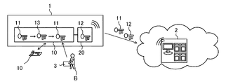
- FIG. 1 is a diagram for explaining the device management system A according to the first embodiment.
- the device management system A has a device 1 and a cloud server 2 which is a device management device.
- the device 1 and the cloud server 2 are connected by a wired and / or wireless network N and communicate with each other.
- the device 1 has a control board 10 and a communication board 20.
- the first identifier 11 is stored in the control board 10.
- the second identifier 12 is stored in the communication board 20.
- the device 1 is, for example, an air conditioner.
- the first identifier 11 is a unique identifier of the device 1 to be managed.
- the first identifier 11 is preferably, but is not limited to, any of the model name, serial number, and identification number on the production line of the device 1.
- the second identifier 12 is an identifier for identifying the device 1 in communication with the device 1.
- the second identifier 12 is preferably any one of a MAC (Media Access Control) address, a UUID (Universal Unique Indicator), an IMEI (International Mobile Equipment Identity), and an IP (Internet protocol) address.
- MAC Media Access Control
- UUID Universal Unique Indicator
- IMEI International Mobile Equipment Identity
- IP Internet protocol
- FIG. 2 is a functional block diagram of the device 1 of the device management system A according to the first embodiment.
- the device 1 has a control unit 1-11, a storage unit S, and a device-side transmission / reception unit 1_1.
- the storage unit S has a first storage unit 1_2 and a second storage unit 1_3.
- the control unit 1_1 performs the device management process of the device 1 according to the first embodiment, and also controls the entire device 1.
- the control unit 1_1 is provided in the device 1 and may be located anywhere.
- the control unit 1_1 may be provided on the control board 10 or the communication board 20.
- the control unit 1_1 may be provided on both the control board 10 and the communication board 20.
- the control unit 1_1 may be provided in addition to the control board 10 and the communication board 20.
- the control unit 1_1 is composed of dedicated hardware or a CPU (also referred to as a Central Processing Unit, a central processing unit, a processing device, a computing device, a microprocessor, a microprocessor, or a processor) that executes a program stored in a memory. ..
- a CPU also referred to as a Central Processing Unit, a central processing unit, a processing device, a computing device, a microprocessor, a microprocessor, or a processor
- the control unit 1_1 corresponds to, for example, a single circuit, a composite circuit, an ASIC (Application Specific Integrated Circuit), an FPGA (Field Programmable Gate Array), or a combination thereof. do.
- Each of the functional units realized by the control unit 1_1 may be realized by individual hardware, or each functional unit may be realized by one hardware.
- each function executed by the control unit 1_1 is realized by software, firmware, or a combination of software and firmware.
- Software and firmware are written as programs and stored in memory.
- the CPU realizes each function of the control unit 1_1 by reading and executing the program stored in the memory.
- the memory is a non-volatile or volatile semiconductor memory such as RAM, ROM, flash memory, EPROM, EEPROM and the like. It should be noted that some of the functions of the control unit 1_1 may be realized by dedicated hardware, and some may be realized by software or firmware.
- the first storage unit 1_2 is provided on the control board 10.
- the first identifier 11 is stored in the first storage unit 1_2.
- the second storage unit 1_3 is provided on the communication board 20.
- the second identifier 12 is stored in the second storage unit 1_3.
- the first identifier 11 is preferably recorded in the control board 10, but is not limited to the control board 10.
- the second identifier 12 is preferably recorded in the communication board 20, but is not limited to the communication board 20. Further, the control board 10 and the communication board 20 may be the same board.
- the device-side transmission / reception unit 1_4 transmits the first identifier 11 stored in the first storage unit 1_2 and the second identifier 12 stored in the second storage unit 1_3.
- the device-side transmission / reception unit 1_4 transmits the third identifier 13 and the second identifier 12.
- the device-side transmission / reception unit 1_4 transmits the first identifier 11 and the fourth identifier 14.
- the third identifier 13 is an identifier that is changed from the first identifier 11 and attached to the device 1 when the configuration of the device 1 is changed due to a failure, repair, or replacement.
- the fourth identifier 14 is an identifier assigned to the device 1 changed from the second identifier 12 in the communication between the device 1 and the cloud server 2.
- FIG. 3 is a diagram showing a hardware configuration of the cloud server 2 in the device management system A according to the first embodiment.
- the cloud server 2 has a CPU 42, a memory 43, a transmission / reception device 44, and a storage device 45 connected to the bus 41.
- the cloud server 2 may be composed of two or more servers.
- the CPU 42 cooperates with the device management program 53 according to the first embodiment stored in the storage device 45 to perform the device management process according to the first embodiment, and also controls the entire cloud server 2. ..
- the memory 43 is used as a work area or the like required when executing the device management process according to the first embodiment.
- the transmission / reception device 44 controls communication with the device 1 outside the cloud server 2 performed via the network N.
- the storage device 45 stores an OS (Operating System) 51, a database 52, and a device management program 53 that performs device management processing according to the first embodiment.
- the storage device 45 is, for example, a large-scale HDD.
- OS51 is a program for realizing the basic functions of the cloud server 2.
- the database 52 stores data used in the device management process by the device management program 53.
- the device management program 53 is a program that controls the device management process according to the first embodiment.
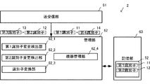
- FIG. 4 is a functional block diagram of the cloud server 2 in the device management system A according to the first embodiment.
- the function of the transmission / reception unit 61 corresponds to the transmission / reception device 44.
- the function of the management unit 62 corresponds to the CPU 42.
- the function of the storage unit 63 corresponds to the storage device 45.
- the storage unit 63 stores in the database 52 the unique first identifier 11 of the device 1 to be managed and the second identifier 12 for identifying the device 1 in the communication between the device 1 and the cloud server 2.
- the first identifier 11 and the second identifier 12 stored in the storage unit 63 are identifiers before the first identifier 11 or the second identifier 12 of the device 1 is changed.
- the transmission / reception unit 61 receives the third identifier 13 and the fourth identifier 14 from the device 1.
- the management unit 62 has a first identifier change detection unit 62_1, a second identifier change detection unit 62_2, an identifier conversion unit 62_3, and a device management unit 62_4.
- the first identifier change detection unit 62_1 detects that the third identifier 13 received by the transmission / reception unit 61 is different from the first identifier 11 stored in the storage unit 63. Specifically, in the first identifier change detection unit 62_1, the third identifier 13 received by the transmission / reception unit 61 is different from the first identifier 11 stored in the storage unit 63, and the second identifier is received by the transmission / reception unit 61. It is detected that the identifier 12 matches the second identifier 12 stored in the storage unit 63.
- the second identifier change detection unit 62_2 detects that the fourth identifier 14 received by the transmission / reception unit 61 is different from the second identifier 12 stored in the storage unit 63. Specifically, in the second identifier change detection unit 62_2, the fourth identifier 14 received by the transmission / reception unit 61 is different from the second identifier 12 stored in the storage unit 63, and the first one received by the transmission / reception unit 61. It is detected that the identifier 11 matches the first identifier 11 stored in the storage unit 63.
- the identifier conversion unit 62_3 converts the third identifier 13 received by the transmission / reception unit 61 into the first identifier 11. Then, the converted first identifier 11 and second identifier 12 are output to the device management unit 62_4. Further, when the change of the second identifier 12 is detected by the second identifier change detection unit 62_2, the identifier conversion unit 62_3 converts the fourth identifier 14 received by the transmission / reception unit 61 into the second identifier 12. Then, the first identifier 11 and the converted second identifier 12 are output to the device management unit 62_4.
- the device management unit 62_4 manages the device 1 that has transmitted the third identifier 13 and the second identifier 12 as the device 1 having the first identifier 11 and the second identifier 12 output from the identifier conversion unit 62_3. Further, the device management unit 62_4 manages the device 1 that has transmitted the first identifier 11 and the fourth identifier 14 as the device 1 having the first identifier 11 and the second identifier 12 output from the identifier conversion unit 62_3.
- the device 1 transmits the first identifier 11 stored in the first storage unit 1-2 of the device 1 and the second identifier 12 stored in the second storage unit 1_3 to the cloud server 2.
- the cloud server 2 stores the first identifier 11 and the second identifier 12 transmitted from the device 1 in the database 52 of the storage unit 63.
- the device-side transmission / reception unit 1_4 uses the third identifier 13 and the second identifier 12 as the cloud server 2. Send to.
- the device-side transmission / reception unit 1_4 transmits the first identifier 11 and the fourth identifier 14 to the cloud server 2. do.
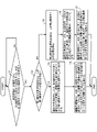
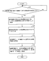
- FIG. 5 is a flowchart for explaining the operation of the cloud server 2 in the device management system A according to the first embodiment.
- the transmission / reception unit 61 of the cloud server 2 determines whether or not the third identifier 13 and the second identifier 12 have been received from the device 1 or the first identifier 11 and the fourth identifier 14 have been received (step S1).
- step S1 when the transmission / reception unit 61 has not received the third identifier 13 and the second identifier 12, or has not received the first identifier 11 and the fourth identifier 14 (NO in step S1), step S1. Continue processing.
- step S1 when the transmission / reception unit 61 receives the third identifier 13 and the second identifier 12 (YES in step S1), it is determined whether the first identifier change detection unit 62_1 has detected the change of the first identifier 11 (YES in step S1). Step S2). Further, in step S1, when it is determined that the transmission / reception unit 61 has received the first identifier 11 and the fourth identifier 14 (YES in step S1), the first identifier change detection unit 62_1 detects the change of the first identifier 11. (Step S2).
- step S2 When it is determined in step S2 that the first identifier change detection unit 62_1 has detected the change of the first identifier 11 (YES in step S2), the identifier conversion unit 62_3 converts the third identifier 13 into the first identifier 11. .. Then, the identifier conversion unit 62_3 outputs the converted first identifier 11 and the second identifier 12 to the device management unit 62_4 (step S3).
- the device management unit 62_4 receives the first identifier 11 and the second identifier 12 output by the identifier conversion unit 62_3.
- the device management unit 62_4 manages the device 1 that has transmitted the third identifier 13 and the second identifier 12 as the device 1 having the first identifier 11 and the second identifier 12 output from the identifier conversion unit 62_3 (step S4).
- step S2 when the first identifier change detection unit 62_1 does not detect the change of the first identifier 11 (NO in step S2), the second identifier change detection unit 62_2 detects the change of the second identifier 12 (step S5). ..
- the identifier conversion unit 62_3 converts the fourth identifier 14 into the second identifier 12. Then, the identifier conversion unit 62_3 outputs the first identifier 11 and the converted second identifier 12 to the device management unit 62_4 (step S6).
- the device management unit 62_4 manages the device 1 that has transmitted the first identifier 11 and the fourth identifier 14 as the device 1 having the first identifier 11 and the second identifier 12 output from the identifier conversion unit 62_3 (step). S7).
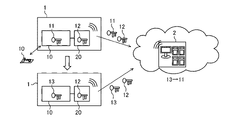
- FIG. 6 is a diagram for explaining a case where the first identifier 11 of the control board 10 of the device 1 in the device management system A according to the first embodiment is changed to the third identifier 13.
- the configuration of the control board 10 of the device 1 changes, and the first identifier 11 of the control board 10 changes to the third identifier 13.
- the device 1 transmits the third identifier 13 and the second identifier 12 to the cloud server 2.
- the cloud server 2 detects that the first identifier 11 of the device 1 has changed, the cloud server 2 converts the third identifier 13 into the first identifier 11. Then, the cloud server 2 manages the device 1 in which the first identifier 11 is changed to the third identifier 13 as the device 1 having the first identifier 11 and the second identifier 12.
- the first identifier 11 is replaced with the second identifier 12
- the second identifier 12 is replaced with the first identifier 11
- the third identifier 13 is replaced with the fourth identifier 14.
- the management process of the device 1 is performed.
- the cloud server 2 may have only the first identifier change detection unit 62_1 or the second identifier change detection unit 62_1.
- FIG. 7 is a flowchart for explaining the operation of a modified example of the cloud server 2 of the device management system A according to the first embodiment.
- the cloud server 2 has only the first identifier change detection unit 62_1 will be described. Further, in FIG. 7, the parts different from those in FIG. 5 will be mainly described.
- the first identifier change detection unit 62_1 is replaced with the second identifier change detection unit 62_2.
- the first identifier 11 is read as the second identifier 12.
- the second identifier 12 is read as the first identifier 11.
- the third identifier 13 is read as the fourth identifier 14.
- step S1_1 it is determined whether or not the third identifier 13 and the second identifier 12 have been received (step S1_1).
- step S1-11 if the transmission / reception unit 61 has not received the third identifier 13 and the second identifier 12 (NO in step S1_1), the process of step S1-1_ is continued.
- step S1-11 when the transmission / reception unit 61 receives the third identifier 13 and the second identifier 12 (YES in step S1_1), the first identifier change detection unit 62_1 detects the change in the first identifier 11 (step S2_1).
- the identifier conversion unit 62_3 converts the third identifier 13 into the first identifier 11. Then, the identifier conversion unit 62_3 outputs the converted first identifier 11 and the second identifier 12 to the device management unit 62_4 (step S3).
- the device management unit 62_4 manages the device 1 to which the third identifier 13 and the second identifier 12 are transmitted as the device 1 having the first identifier 11 and the second identifier 12. do. Further, the device management unit 62_4 manages the device 1 that has transmitted the first identifier 11 and the fourth identifier 14 as the device 1 having the first identifier 11 and the second identifier 12 output by the identifier conversion unit 62_3. As a result, the device management system A can manage the device 1 as substantially the same device 1 as before the change even if a part of the configuration is changed due to the repair and replacement of the device 1. ..
- the device 1 can be continuously managed from the time the device 1 is installed until it is disposed of after failure, repair or replacement.
- Embodiment 2 Next, the device management system A according to the second embodiment will be described.
- the device 1 of the device management system A of the second embodiment has the control board 10 and the communication board 20 as shown in FIG. 1, similarly to the device management system A of the first embodiment.
- the device 1 converts the third identifier 13 into the first identifier 11. Further, the device 1 converts the fourth identifier 14 into the second identifier 12. Then, the device 1 transmits the first identifier 11 and the second identifier 12 to the cloud server 2.
- FIG. 8 is a functional block diagram of the device 1 in the device management system A according to the second embodiment.
- the device 1 includes a control unit 70, a device-side transmission / reception unit 71, and a first storage unit 72_4.
- the control unit 70 has a first identifier change detection unit 72_1, a second identifier change detection unit 72_2, and an identifier conversion unit 72_3.
- control unit 70 the device-side transmission / reception unit 71, and the first storage unit 72_4 are provided on the communication board 20 of the device 1, but may be provided at another location of the device 1.
- the first identifier 11 and the second identifier 12 are stored in the first storage unit 72_4.
- the device-side transmission / reception unit 71 receives the third identifier 13 and the second identifier 12 that are attached when the configuration of the device 1 is changed. Further, it is changed from the first identifier 11 and the second identifier 12, and receives the fourth identifier 14 for identifying the device 1 in the communication between the device 1 and the cloud server 2.
- the first identifier change detection unit 72_1 is different from the first identifier 11 in which the third identifier 13 received from the device 1 whose configuration has been changed by the device-side transmission / reception unit 71 is stored in the first storage unit 72_4, and the device-side transmission / reception unit 72_1.
- the second identifier 12 received by 71 matches the second identifier 12 stored in the first storage unit 72_4, the change of the first identifier 11 is detected.
- the second identifier change detection unit 72_2 is different from the second identifier 12 in which the fourth identifier 14 received by the device-side transmission / reception unit 71 is stored in the first storage unit 72_4, and the first identifier received by the device-side transmission / reception unit 71.
- 11 matches the first identifier 11 stored in the first storage unit 72_4, the change of the second identifier 12 is detected.
- the identifier conversion unit 72_3 converts the third identifier 13 received by the device-side transmission / reception unit 71 into the first identifier 11 and converts it.
- the first identifier 11 and the second identifier 12 are output.
- the identifier conversion unit 72_3 converts the fourth identifier 14 received by the device-side transmission / reception unit 71 into the second identifier 12, and the second identifier. 1
- the identifier 11 and the converted second identifier 12 are output to the device-side transmission / reception unit 71.
- the device-side transmission / reception unit 71 transmits the first identifier 11 and the second identifier 12 output by the identifier conversion unit 72_3 to the cloud server 2.
- FIG. 9 is a functional block diagram of the cloud server 2 in the device management system A according to the second embodiment.
- the cloud server 2 includes a transmission / reception unit 71_2, a device management unit 72_5, and a second storage unit 72_6.
- the transmission / reception unit 71_2 receives the first identifier 11 and the second identifier 12 transmitted from the device 1.
- the second storage unit 72_6 stores the first identifier 11 and the second identifier 12 of the device 1 before the change in the database 52.
- the device management unit 72_5 When the device management unit 72_5 receives the first identifier 11 and the second identifier 12 transmitted from the device-side transmission / reception unit 71 of the device 1, the device 1 in which the first identifier 11 is changed is stored in the second storage unit 72_6. It is managed as a device 1 having the first identifier 11 and the second identifier 12.
- the device management unit 72_5 receives the first identifier 11 and the second identifier 12 transmitted from the device-side transmission / reception unit 71 of the device 1, the device 1 in which the second identifier 12 is changed is stored in the second storage unit 72_6. It is managed as a device 1 having the first identifier 11 and the second identifier 12.
- the device 1 before the first identifier 11 and the second identifier 12 are changed transmits the first identifier 11 and the second identifier 12 stored in the first storage unit 72_4 of the device 1 to the cloud server 2. ..
- the cloud server 2 stores the first identifier 11 and the second identifier 12 transmitted from the device 1 in the database 52 of the second storage unit 72_6.
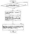
- FIG. 10 is a flowchart for explaining the operation of the device 1 in the device management system A according to the second embodiment.
- the transmission / reception unit 71_2 determines whether or not the third identifier 13 and the second identifier 12 have been received from the device-side transmission / reception unit 71 of the device 1, or the first identifier 11 and the fourth identifier 14 have been received (step S11). ).
- step S11 if the transmission / reception unit 71_2 has not received the third identifier 13 and the second identifier 12, or has not received the first identifier 11 and the fourth identifier 14 (NO in step S11), step S11. Continue processing.
- step S11 when the device-side transmission / reception unit 71 receives the third identifier 13 and the second identifier 12 (YES in step S11), it is determined whether the first identifier change detection unit 72_1 has detected the change of the first identifier 11. (Step S12).
- step S12 When it is determined in step S12 that the first identifier change detection unit 72_1 has detected the change of the first identifier 11 (YES in step S12), the identifier conversion unit 72_3 converts the third identifier 13 into the first identifier 11. .. Then, the identifier conversion unit 72_3 outputs the converted first identifier 11 and the second identifier 12 (step S13).
- the device-side transmission / reception unit 71 transmits the first identifier 11 and the second identifier 12 output by the identifier conversion unit 72_3 to the cloud server 2 (step S14).
- step S12 when it is determined that the first identifier change detection unit 72_1 does not detect the change of the first identifier 11 (NO in step S12), the second identifier change detection unit 72_2 detects the change of the second identifier 12 (NO). Step S15).
- the identifier conversion unit 72_3 converts the fourth identifier 14 into the second identifier 12. Then, the identifier conversion unit 72_3 outputs the first identifier 11 and the converted second identifier 12 (step S16). After that, the process proceeds to step S14.
- FIG. 11 is a flowchart for explaining the operation of the cloud server 2 in the device management system A according to the second embodiment.
- step S21 it is determined whether the transmission / reception unit 71_2 has received the first identifier 11 and the second identifier 12 from the device 1 (step S21).
- step S21 If it is determined in step S21 that the transmission / reception unit 71_2 has not received the first identifier 11 and the second identifier 12 from the device 1 (NO in step S21), the process of step S21 is continued.
- step S21 when the transmission / reception unit 71_2 receives the first identifier 11 and the second identifier 12 from the device 1 (YES in step S21), the device management unit 72_5 uses the device 1 to which the first identifier 11 has been changed. It is managed as a device 1 having the first identifier 11 and the second identifier 12 stored in the second storage unit 72_6 (step S22).
- FIG. 12 is a diagram for explaining a case where the first identifier 11 of the control board 10 of the device 1 in the device management system A according to the second embodiment is changed to the third identifier 13.
- the configuration of the device 1 changes, and the first identifier 11 of the control board 10 of the device 1 is converted into the third identifier 13.
- the first identifier change detection unit 72_1 of the control unit 70 of the device 1 detects the change of the first storage unit 72_4 based on the second identifier 12
- the third identifier 13 is converted into the first identifier 11.
- the device-side transmission / reception unit 71 of the device 1 transmits the converted first identifier 11 and the second identifier 12 to the cloud server 2.
- the cloud server 2 manages the device 1 in which the first identifier 11 is changed in the same manner as the device 1 having the first identifier 11 and the second identifier 12.
- the second identifier 12 when the second identifier 12 changes, the first identifier 11 is replaced with the second identifier 12, the second identifier 12 is replaced with the first identifier 11, and the third identifier 13 is replaced with the fourth identifier 14.
- the management process of the device 1 is performed.
- the device 1 may have only the first identifier change detection unit 72_1 or the second identifier change detection unit 72_1.
- FIG. 13 is a flowchart for explaining the operation of a modified example of the device 1 of the device management system A according to the second embodiment.
- the device 1 has only the first identifier change detection unit 72_1 will be described. Further, in FIG. 13, a portion different from that in FIG. 10 will be mainly described.
- step S11_1 when the third identifier 13 and the second identifier 12 are received in step S11_1 (YES in step S11_1), the first identifier change detection unit 62_1 detects the change of the first identifier 11 (step). S12_1). If the third identifier 13 and the second identifier 12 have not been received in step S11_1 (NO in step S11_1), the process of step S11_1 is continued.
- the identifier conversion unit 62_3 converts the third identifier 13 into the first identifier 11. Then, the identifier conversion unit 62_3 outputs the converted first identifier 11 and the second identifier 12 to the device management unit 62_4 (step S13).
- the third identifier 13 is converted to the first identifier 11, or the fourth identifier 14 is converted to the second identifier 12. Therefore, as compared with the device management system A of the first embodiment, the load of the identifier conversion process in the cloud server 2 and the operating cost of the cloud server 2 can be reduced.
- FIG. 14 is a diagram for explaining a case where the third identifier 13 stored in the control board 10 in the device management system A according to the third embodiment is rewritten to the first identifier 11.
- the device management system A of the third embodiment converts the third identifier 13 or the fourth identifier 14 in addition to the device management system A of the first embodiment and the device management system A of the second embodiment of the repair worker. It can be performed by the first information processing apparatus 3.
- the configuration of the control board 10 of the device 1 changes, and the first identifier 11 of the control board 10 changes to the third identifier 13.
- the repair worker B rewrites the third identifier 13 stored in the control board 10 of the device 1 with the first identifier 11.
- the first information processing device 3 may rewrite the fourth identifier 14 to the second identifier 12.
- the first information processing device 3 rewrites the third identifier 13 stored in the first storage unit 1_2, which is the device side storage unit, to the first identifier 11. .. Further, the first information processing apparatus 3 may rewrite the fourth identifier 14 stored in the second storage unit 1_3.
- the device-side transmission / reception unit 1_4 transmits the first identifier 11 rewritten by the first information processing device 3 and the second identifier 12 stored in the second storage unit 1_3 to the cloud server 2.
- the device 1 to which the first identifier 11 or the second identifier 12 is changed is managed as the device 1 having the first identifier 11 and the second identifier 12.
- FIG. 15 is a diagram for explaining rewriting of the third identifier 13 by the first information processing apparatus 3 in the device management system A according to the third embodiment.
- the first information processing apparatus 3 rewrites the third identifier 13 to the first identifier 11, so that the cloud server 2 needs to perform the conversion process of the third identifier 13. do not have.
- the first identifier 11 and the second identifier 12 can be rewritten by the first information processing apparatus 3, so that the device 1 can be appropriately managed. ..
- Embodiment 4 Next, the device management system A according to the fourth embodiment will be described.
- the device management system A of the fourth embodiment detects a specific operation on the device 1 after the device 1 is repaired or replaced. Then, the device 1 transmits the repair information of the device 1 to the cloud server 2 after the specific operation is detected.
- the cloud server 2 manages repair information of the device 1 in association with the first identifier 11 and the second identifier 12.
- FIG. 16 is a functional block diagram of the device 1 in the device management system A according to the fourth embodiment.
- the same parts as those in FIG. 15 are designated by the same reference numerals, and the description thereof will be omitted.
- control unit 70 of the device 1 has a specific operation detection unit 81 and a repair information creation unit 82.
- the specific operation detection unit 81 detects a specific operation for the device 1.
- the specific operation is performed after the repair or replacement of the device 1 is completed.
- the specific operation is, for example, an operation such as repeatedly pressing the test run button 10 times during the operation of the device 1.
- the specific operation detection unit 81 is provided in the device 1, it may be provided in the first information processing device 3 and the first information processing device 3 may detect the specific operation and notify the device 1.
- the repair information creation unit 82 creates repair information 80 indicating that the device 1 has been repaired or replaced when the specific operation is detected by the specific operation detection unit 81, and stores the created repair information 80 for the first time. Stored in part 72_4.
- the repair information 80 is information stored in association with the first identifier 11 and the second identifier 12.
- the repair information 80 includes information indicating that the repair or replacement of the device 1 is completed.
- Repair of device 1 includes repair or replacement of parts of device 1.
- the repair information 80 also includes information on the repair of the device 1, for example, information on the parts of the device 1 that has been repaired or replaced, information on an abnormality, owner information, user information, sensor information, and information on the next replacement part. And may include information indicating when to replace the part.
- the device-side transmission / reception unit 71 transmits the repair information 80 created by the repair information creation unit 82 to the cloud server 2.
- FIG. 17 is a functional block diagram of the cloud server 2 in the device management system A according to the fourth embodiment.
- the same parts as those in FIG. 9 are designated by the same reference numerals, and the description thereof will be omitted.
- the transmission / reception unit 71_2 receives the repair information 80 transmitted from the device 1.
- the device management unit 72_5 of the cloud server 2 stores and manages the repair information 80 transmitted from the transmission / reception unit 71_2 in the second storage unit 72_6 in association with the first identifier 11 and the second identifier 12. do.
- FIG. 18 is a flowchart of the device 1 and the cloud server 2 for explaining the operation of the device management system A according to the fourth embodiment.
- the processing operations of the first identifier 11 and the second identifier 12 are the same as those in FIG.
- the processing operation of the repair information 80 will be described.
- step S31 It is determined whether the specific operation detection unit 81 has detected a specific operation for the device 1 (step S31).
- step S31 If it is determined in step S31 that the specific operation detection unit 81 has not detected the specific operation for the device 1 (NO in step S31), the determination process in step S31 is continued.
- the repair information creation unit 82 creates the repair information 80, and the created repair information 80 is stored in the first storage unit. Store in 72_4 (step S32).
- the device-side transmission / reception unit 71 transmits the repair information to the cloud server 2 (step S33).
- the transmission / reception unit 71_2 of the cloud server 2 receives the repair information 80 transmitted from the device 1 (step S34).
- the device management unit 72_5 stores and manages the repair information 80 in the second storage unit 72_6 in association with the first identifier 11 and the second identifier 12 (step S35).
- the cloud server 2 manages the repair information 80 in association with the first identifier 11 and the second identifier 12. Therefore, the device 1 can be appropriately managed including the repair information 80.
- Embodiment 5 Next, the device management system A according to the fifth embodiment will be described.
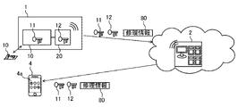
- FIG. 19 is a diagram for explaining the device management system A according to the fifth embodiment.
- the cloud server 2 transmits the first identifier 11, the second identifier 12, and the repair information 80 transmitted from the device 1 to the second information processing device 4.
- the second information processing device 4 has a display unit 4a, and the second information processing device 4 displays the first identifier 11, the second identifier 12, and the repair information 80 transmitted from the cloud server 2 on the display unit 4a.
- the cloud server 2 stores the first identifier 11, the second identifier 12, and the repair information 80 in the second storage unit 72_6.
- Communication is performed between the cloud server 2 and the second information processing device 4 using a public radio line or a short-range radio.
- Communication using a public wireless line is LTE (Long Term Evolution) communication or 5G (5th Generation) communication.
- Near field communication is Wi-Fi or Bluetooth®.
- the second information processing apparatus 4 may read out the first identifier 11, the second identifier 12, and the repair information 80 displayed on the display unit 4a by voice.
- FIG. 20 is a flowchart for explaining the operation of the device management system A according to the fifth embodiment.
- the cloud server 2 transmits the first identifier 11, the second identifier 12, and the repair information 80 to the second information processing device 4 (step S41).
- the second information processing apparatus 4 displays the first identifier 11, the second identifier 12, and the repair information 80 on the display unit 4a (step S42).
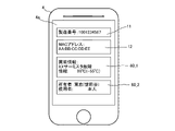
- FIG. 21 is a diagram showing an example of information displayed on the display unit 4a of the second information processing apparatus 4 of the device management system A according to the fifth embodiment.
- the display unit 4a of the second information processing apparatus 4 has a first identifier 11 indicating a serial number, a second identifier 12 indicating a MAC address, repair information 80_1 indicating abnormality information, and owner information.
- the repair information 80_2 indicating the user's feeling is displayed.
- FIG. 22 is a diagram showing another example of information displayed on the display unit 4a of the second information processing apparatus 4 of the device management system A according to the fifth embodiment.
- the first identifier 11 indicating the serial number, the second identifier 12 indicating the MAC address, the repair information 80_1 indicating the abnormality information, and the replacement of parts are displayed.
- Repair information 80_3 indicating completion is displayed.
- FIG. 23 is a diagram showing another example of information displayed on the display unit 4a of the second information processing apparatus 4 of the device management system A according to the fifth embodiment.
- the display unit 4a of the second information processing apparatus 4 has a first identifier 11 indicating a serial number, a second identifier 12 indicating a MAC address, repair information 80_1 indicating abnormality information, and replacement of parts. Repair information 80_4 indicating that it is necessary is displayed.
- the case where the identifier conversion is performed in the device 1 as in the second embodiment is shown, but the case where the identifier conversion is performed in the cloud server 2 as in the first embodiment is also shown. Applicable.
- the second information processing apparatus 4 displays the first identifier 11, the second identifier 12, and the repair information 80 on the device 1, so that the user can accurately manage the device 1. can.
- Embodiment 6 Next, the device management system A according to the sixth embodiment will be described.
- FIG. 24 is a diagram for explaining the device management system A according to the sixth embodiment.
- the cloud server 2 is connected to the maintenance server 5.
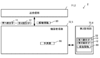
- the cloud server 2 predicts the life of the replacement parts of the device 1.
- the maintenance server 5 manages the inventory data 5a of the replacement parts based on the life of the replacement parts predicted by the cloud server 2.
- FIG. 25 is a functional block diagram of the cloud server 2 in the device management system A according to the sixth embodiment.
- the same parts as those in FIG. 17 are designated by the same reference numerals, and the description thereof will be omitted.
- the prediction unit 90 predicts the life of the replacement part of the device 1 based on the repair information 80. Specifically, the prediction unit 90 refers to the service life specified in the rating of the replacement part of the device 1 from the information regarding the replacement part of the device 1 included in the repair information 80, and refers to the replacement part of the device 1. Predict the life of the.
- the method of predicting the replacement part of the device 1 by the prediction unit 90 is not limited to this.
- the prediction unit 90 may predict the timing of the next repair or replacement of the device 1, the failure prediction of the device 1, and the life of the device 1 based on the repair information 80.
- the target of prediction and the method of prediction do not matter.
- the transmission / reception unit 71_2 transmits the life of the replacement part of the device 1 predicted by the prediction unit 90 to the maintenance server 5.
- the maintenance server 5 has inventory data 5a.
- the maintenance server 5 manages the inventory data 5a of the replacement parts based on the life of the replacement parts of the device 1 predicted by the prediction unit 90. Specifically, the maintenance server 5 manages the inventory data 5a so that the replacement parts are arranged in the order of the shortest life of the replacement parts.
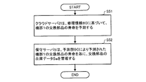
- FIG. 26 is a flowchart for explaining the operation of the device management system A according to the sixth embodiment.
- the cloud server 2 predicts the life of the replacement part of the device 1 based on the repair information 80 (step S51).
- the maintenance server 5 manages the inventory data 5a of the replacement parts based on the life of the replacement parts of the device 1 predicted by the prediction unit 90 (step S52).
- the maintenance server 5 manages the inventory data 5a of the replacement parts based on the life of the replacement parts of the device 1. Therefore, it is possible to shorten the time from when the repair company orders a replacement part and obtains the replacement part to when the repair is performed. As a result, the service quality of the management of the device 1 can be improved.
Landscapes
- Engineering & Computer Science (AREA)
- Physics & Mathematics (AREA)
- General Physics & Mathematics (AREA)
- Automation & Control Theory (AREA)
- Signal Processing (AREA)
- Computer And Data Communications (AREA)
- Telephonic Communication Services (AREA)
Abstract
Description
図1は、実施の形態1に係る機器管理システムAを説明するための図である。
図2は、実施の形態1に係る機器管理システムAの機器1の機能ブロック図である。
図3は、実施の形態1に係る機器管理システムAにおけるクラウドサーバ2のハードウェア構成を示す図である。
図4は、実施の形態1に係る機器管理システムAにおけるクラウドサーバ2の機能ブロック図である。
次に、実施の形態1に係る機器管理システムAの動作について説明する。
実施の形態1の機器管理システムAでは、クラウドサーバ2が第1識別子変更検出部62_1及び第2識別子変更検出部62_2を具備する場合について説明した。
次に、実施の形態1に係る機器管理システムAの効果について説明する。
次に、実施の形態2に係る機器管理システムAについて説明する。実施の形態2の機器管理システムAの機器1は、実施の形態1の機器管理システムAと同様に、図1に示したように、制御基板10及び通信基板20を有する。
次に、実施の形態2に係る機器管理システムAの動作について説明する。
実施の形態2の機器管理システムAでは、機器1が第1識別子変更検出部72_1及び第2識別子変更検出部72_2を具備する場合について説明した。
次に、実施の形態2に係る機器管理システムAの効果について説明する。
次に、実施の形態3に係る機器管理システムAについて説明する。図14は、実施の形態3に係る機器管理システムAにおける制御基板10に記憶された第3識別子13を第1識別子11に書き直す場合を説明するための図である。
実施の形態3に係る機器管理システムAによれば、第1情報処理装置3が第3識別子13を第1識別子11に書き換えるので、クラウドサーバ2は、第3識別子13の変換処理を行なう必要がない。
次に、実施の形態4に係る機器管理システムAについて説明する。実施の形態4の機器管理システムAは、機器1の修理又は交換後に機器1に対する特定操作を検出する。そして、機器1は、特定操作が検出された後に、機器1の修理情報をクラウドサーバ2に送信する。クラウドサーバ2は、第1識別子11及び第2識別子12に関連付けて、機器1の修理情報を管理する。
実施の形態4に係る機器管理システムAによれば、クラウドサーバ2は、第1識別子11及び第2識別子12に関連付けて修理情報80を管理する。従って、機器1を修理情報80を含めた形で適切に管理できる。
次に、実施の形態5に係る機器管理システムAについて説明する。
実施の形態5に係る機器管理システムAによれば、第2情報処理装置4が機器1に第1識別子11、第2識別子12及び修理情報80を表示するので、ユーザは機器1を正確に管理できる。
次に、実施の形態6に係る機器管理システムAについて説明する。
実施の形態6に係る機器管理システムAによれば、保守サーバ5が機器1の交換部品の寿命を基に、交換部品の在庫データ5aを管理する。従って、修理業者が交換部品を発注し、交換部品を入手してから修理にあたるまでの時間を短縮できる。その結果、機器1の管理のサービス品質を向上できる。
Claims (8)
- 管理対象となる機器と、
前記機器を管理する機器管理装置と
を具備し、
前記機器は、
前記機器管理装置と通信を行なう機器側送受信部を具備し、
前記機器管理装置は、
前記機器の固有の第1識別子と、前記機器と前記機器管理装置との通信において前記機器を識別する第2識別子とを記憶する記憶部と、
前記機器の構成が変更された場合に前記第1識別子が変更されて付される第3識別子及び前記第2識別子を前記機器側送受信部から受信する送受信部と、
前記送受信部により受信された前記第3識別子が前記記憶部に記憶された前記第1識別子と異なり、かつ前記送受信部により受信された前記第2識別子が前記記憶部に記憶された前記第2識別子と一致する場合、前記第1識別子の変更を検出する第1識別子変更検出部と、
前記第1識別子変更検出部により前記第1識別子の変更が検出された場合、前記送受信部により受信した前記第3識別子を前記第1識別子に変換し、前記変換された前記第1識別子及び前記第2識別子を出力する識別子変換部と、
前記第3識別子及び前記第2識別子を送信した前記機器を前記識別子変換部から出力された前記第1識別子及び前記第2識別子を有する前記機器として管理する機器管理部と
を具備する機器管理システム。 - 前記送受信部は、
前記第1識別子及び第4識別子を前記機器側送受信部から受信し、前記第4識別子は、前記第2識別子から変更され、前記機器と前記機器管理装置との通信において前記機器を識別する前記第2識別子が変更されて付される識別子であり、
前記機器管理装置は、
前記送受信部により受信された前記第4識別子が、前記記憶部に記憶された前記第2識別子と異なり、かつ前記送受信部により受信された前記第1識別子が前記記憶部に記憶された前記第1識別子と一致する場合、前記第2識別子の変更を検出する第2識別子変更検出部を具備し、
前記識別子変換部は、
前記第2識別子変更検出部により第2識別子の変更が検出された場合、前記送受信部により受信した前記第4識別子を第2識別子に変換し、前記第1識別子及び前記変換された第2識別子を出力し、
前記機器管理部は、
前記第1識別子及び前記第4識別子を送信した機器を前記識別子変換部から出力された前記第1識別子及び前記第2識別子を有する前記機器として管理する
請求項1に記載の機器管理システム。 - 管理対象となる機器と、
前記機器を管理する機器管理装置と
を具備し、
前記機器は、
前記機器の固有の第1識別子及び前記機器と前記機器管理装置との通信において前記機器を識別する第2識別子が記憶された第1記憶部と、
前記機器の構成が変更された場合に前記第1識別子が変更されて付される第3識別子及び前記第2識別子を受信する機器側送受信部と、
前記機器側送受信部により受信された前記第3識別子が前記第1記憶部に記憶された前記第1識別子と異なり、前記機器側送受信部により受信された前記第2識別子が前記第1記憶部に記憶された前記第2識別子と一致する場合、前記第1識別子の変更を検出する第1識別子変更検出部と、
前記第1識別子変更検出部により前記第1識別子の変更が検出された場合、前記機器側送受信部により受信した前記第3識別子を前記第1識別子に変換し、前記変換された第1識別子及び第2識別子を出力する識別子変換部と
を具備し、
前記機器側送受信部は、前記識別子変換部により出力された前記第1識別子及び前記第2識別子を前記機器管理装置に送信し、
前記機器管理装置は、
前記機器側送受信部から送信された前記第1識別子及び前記第2識別子を受信する送受信部と
前記第3識別子及び前記第2識別子を送信した前記機器を前記送受信部により受信された前記第1識別子及び前記第2識別子を有する前記機器として管理する機器管理部と
を具備する機器管理システム。 - 前記第1記憶部は、
前記第3識別子と、前記第2識別子とを記憶し、
前記第1記憶部に記憶された前記第3識別子を前記第1識別子に書き換え可能な第1情報処理装置を具備し、
前記機器側送受信部は、前記第1情報処理装置により書き換えられた前記第1識別子及び前記第1記憶部に記憶された前記第2識別子を前記機器管理装置に送信する
請求項3に記載の機器管理システム。 - 前記機器は、
前記機器に対する特定操作を検出する特定操作検出部と、
前記特定操作検出部により特定操作が検出された場合、前記機器の修理又は交換が行われたことを示す修理情報を作成する修理情報作成部と
を具備し、
前記機器側送受信部は、前記修理情報作成部により作成された前記修理情報を前記機器管理装置に送信し、
前記機器管理装置は、
前記機器側送受信部から送信された前記修理情報を前記第1識別子及び前記第2識別子に関連付けて管理する
請求項1~4のいずれか1項に記載の機器管理システム。 - 表示部を有する第2情報処理装置を具備し、
前記機器管理装置は、前記第1識別子及び前記第2識別子を前記第2情報処理装置に送信し、
前記第2情報処理装置は、前記機器管理装置から前記第1識別子及び前記第2識別子を受信し、前記受信した前記第1識別子及び前記第2識別子を前記表示部に表示する
請求項1~5のいずれか1項に記載の機器管理システム。 - 前記第2情報処理装置は、
前記修理情報を前記機器管理装置から受信し、前記受信した前記修理情報を前記表示部に表示する
請求項6に記載の機器管理システム。 - 前記機器管理装置と接続され、前記機器の交換部品の在庫データを管理する保守サーバを具備し、
前記機器管理装置は、前記修理情報に基づいて、前記機器の交換部品の寿命を予測する予測部を具備し、
前記保守サーバは、前記予測部により予測された前記機器の交換部品の寿命を基に、前記交換部品の在庫データを管理する
請求項5に記載の機器管理システム。
Priority Applications (5)
| Application Number | Priority Date | Filing Date | Title |
|---|---|---|---|
| JP2022567964A JP7407972B2 (ja) | 2020-12-10 | 2020-12-10 | 機器管理システム |
| PCT/JP2020/045987 WO2022123717A1 (ja) | 2020-12-10 | 2020-12-10 | 機器管理システム |
| CN202080107075.3A CN116569540B (zh) | 2020-12-10 | 2020-12-10 | 设备管理系统 |
| US18/251,148 US12547138B2 (en) | 2020-12-10 | 2020-12-10 | Device management system |
| DE112020007830.2T DE112020007830T5 (de) | 2020-12-10 | 2020-12-10 | Gerätemanagementsystem |
Applications Claiming Priority (1)
| Application Number | Priority Date | Filing Date | Title |
|---|---|---|---|
| PCT/JP2020/045987 WO2022123717A1 (ja) | 2020-12-10 | 2020-12-10 | 機器管理システム |
Publications (1)
| Publication Number | Publication Date |
|---|---|
| WO2022123717A1 true WO2022123717A1 (ja) | 2022-06-16 |
Family
ID=81973462
Family Applications (1)
| Application Number | Title | Priority Date | Filing Date |
|---|---|---|---|
| PCT/JP2020/045987 Ceased WO2022123717A1 (ja) | 2020-12-10 | 2020-12-10 | 機器管理システム |
Country Status (5)
| Country | Link |
|---|---|
| US (1) | US12547138B2 (ja) |
| JP (1) | JP7407972B2 (ja) |
| CN (1) | CN116569540B (ja) |
| DE (1) | DE112020007830T5 (ja) |
| WO (1) | WO2022123717A1 (ja) |
Citations (3)
| Publication number | Priority date | Publication date | Assignee | Title |
|---|---|---|---|---|
| JP2003167966A (ja) * | 2001-11-29 | 2003-06-13 | Mitsubishi Electric Corp | 定期保守管理システム |
| JP2009282779A (ja) * | 2008-05-22 | 2009-12-03 | Panasonic Electric Works Co Ltd | 連動システム |
| WO2014175439A1 (ja) * | 2013-04-26 | 2014-10-30 | 三菱電機株式会社 | 通信装置、アドレス管理方法、プログラム及び通信システム |
Family Cites Families (22)
| Publication number | Priority date | Publication date | Assignee | Title |
|---|---|---|---|---|
| JPH0546672A (ja) * | 1991-08-15 | 1993-02-26 | Matsushita Electric Ind Co Ltd | 情報処理装置 |
| CN1930838A (zh) * | 2004-01-30 | 2007-03-14 | 松下电器产业株式会社 | 信息处理装置、服务器、通信系统、地址决定方法、地址变更方法及程序 |
| KR100613508B1 (ko) * | 2004-03-22 | 2006-08-17 | 엘지전자 주식회사 | 에어컨의 중앙제어 시스템 및 그 동작방법 |
| US20070080823A1 (en) * | 2005-10-07 | 2007-04-12 | Apple Computer, Inc. | Techniques for pairing remote controllers with host devices |
| JP2009251649A (ja) * | 2008-04-01 | 2009-10-29 | Olympus Corp | サーバシステム、電子機器、通信端末及び認証方法 |
| US8099251B2 (en) * | 2008-10-17 | 2012-01-17 | Dell Products L.P. | Systems and methods for certifying a racked computer assembly |
| TWI449391B (zh) * | 2008-10-28 | 2014-08-11 | Ind Tech Res Inst | 識別碼的產生與辨識方法與通訊系統 |
| US8418211B2 (en) * | 2008-12-31 | 2013-04-09 | Echostar Technologies L.L.C. | Antenna diversity for control device applications |
| US8525651B2 (en) * | 2011-03-25 | 2013-09-03 | Echostar Technologies L.L.C. | Apparatus, systems and methods for pairing a controlled device with an RF remote control using an RFID tag |
| US8941784B2 (en) * | 2011-09-01 | 2015-01-27 | Echostar Technologies L.L.C. | Easy RF remote control pairing for networked set top boxes |
| US10404801B2 (en) * | 2011-11-08 | 2019-09-03 | DISH Technologies L.L.C. | Reconfiguring remote controls for different devices in a network |
| US8983387B1 (en) * | 2012-06-28 | 2015-03-17 | Google Inc. | Apparatus and methods for remote control of electronic devices |
| US9070280B2 (en) * | 2013-01-24 | 2015-06-30 | L&P Property Mangement Company | Remote and controller synchronization for automated furniture controls |
| US9210357B1 (en) * | 2013-03-13 | 2015-12-08 | Google Inc. | Automatically pairing remote |
| FR3011706B1 (fr) * | 2013-10-07 | 2017-03-03 | Schneider Electric Ind Sas | Dispositif de configuration d'equipements ethernet et procede de configuration d'equipements ethernet a l'aide d'un tel dispositif |
| US10142668B1 (en) * | 2014-03-12 | 2018-11-27 | Cox Communications, Inc. | Pairing wireless set-top box with a wired set-top box |
| US9721466B2 (en) * | 2014-10-31 | 2017-08-01 | Comcast Cable Communications, Llc | Method of pairing a remote control |
| US9560407B2 (en) * | 2015-02-26 | 2017-01-31 | Verizon Patent And Licensing Inc. | Systems and methods for managing pairing of remote control devices with a plurality of media content processing devices |
| US11252237B2 (en) | 2018-03-02 | 2022-02-15 | Panasonic Intellectual Property Management Co., Ltd. | Device management system and device management method |
| WO2019172046A1 (ja) * | 2018-03-09 | 2019-09-12 | パナソニックIpマネジメント株式会社 | 機器管理方法、及び、機器管理システム |
| US11943622B2 (en) * | 2020-03-06 | 2024-03-26 | Dish Network Technologies India Pvt. Ltd. | Systems and methods for managing remote control units and paired devices |
| WO2021250860A1 (ja) * | 2020-06-11 | 2021-12-16 | 日本電信電話株式会社 | アドレス設定システム、アドレス設定方法、アドレス設定管理装置及びプログラム |
-
2020
- 2020-12-10 DE DE112020007830.2T patent/DE112020007830T5/de active Pending
- 2020-12-10 WO PCT/JP2020/045987 patent/WO2022123717A1/ja not_active Ceased
- 2020-12-10 CN CN202080107075.3A patent/CN116569540B/zh active Active
- 2020-12-10 US US18/251,148 patent/US12547138B2/en active Active
- 2020-12-10 JP JP2022567964A patent/JP7407972B2/ja active Active
Patent Citations (3)
| Publication number | Priority date | Publication date | Assignee | Title |
|---|---|---|---|---|
| JP2003167966A (ja) * | 2001-11-29 | 2003-06-13 | Mitsubishi Electric Corp | 定期保守管理システム |
| JP2009282779A (ja) * | 2008-05-22 | 2009-12-03 | Panasonic Electric Works Co Ltd | 連動システム |
| WO2014175439A1 (ja) * | 2013-04-26 | 2014-10-30 | 三菱電機株式会社 | 通信装置、アドレス管理方法、プログラム及び通信システム |
Also Published As
| Publication number | Publication date |
|---|---|
| JPWO2022123717A1 (ja) | 2022-06-16 |
| US20230375996A1 (en) | 2023-11-23 |
| US12547138B2 (en) | 2026-02-10 |
| CN116569540B (zh) | 2024-09-17 |
| CN116569540A (zh) | 2023-08-08 |
| JP7407972B2 (ja) | 2024-01-04 |
| DE112020007830T5 (de) | 2023-11-23 |
Similar Documents
| Publication | Publication Date | Title |
|---|---|---|
| EP2367337B1 (en) | Field communication system and field communication method | |
| CN107636702A (zh) | 集成式资产完整性管理系统 | |
| US9296266B1 (en) | Method for correcting ID codes after installation of tire pressure sensors on a vehicle | |
| US11613285B2 (en) | Method for operating a rail vehicle | |
| CN103026661A (zh) | 设备调试和替换 | |
| CN105137922A (zh) | 现场设备管理系统 | |
| JP2013002725A (ja) | 空気調和機 | |
| JP2020147250A (ja) | 電子制御装置 | |
| CN105706380A (zh) | 通信装置、通信系统、服务器、通信方法以及非暂时性记录介质 | |
| JP6177455B2 (ja) | 管理システム | |
| JP6089356B2 (ja) | 機器管理装置、機器管理システム | |
| KR102057809B1 (ko) | 버스정류소 안내단말기 관리시스템 및 그 구동 방법 | |
| WO2022123717A1 (ja) | 機器管理システム | |
| US20190037017A1 (en) | Information processing device, information processing method, information processing program and information processing system | |
| JP6815978B2 (ja) | 遠隔監視システムおよび監視対象設備の初期設定方法 | |
| CN109557897B (zh) | 通知控制装置、通知控制系统、通知控制方法及存储介质 | |
| KR100695533B1 (ko) | 유비쿼터스 기술을 적용한 생산 관리 시스템 | |
| JP4920544B2 (ja) | 空気調和機、サポートシステム | |
| JP7453782B2 (ja) | 機器管理装置 | |
| CN103580974A (zh) | 在控制器的设备中存储规定地址的方法 | |
| JP5845459B2 (ja) | 機器登録方法、および機器登録システム | |
| KR20230000242A (ko) | 자동화 장비 관리 시스템 및 그 방법 | |
| KR100458950B1 (ko) | 항온항습기 무선 관리시스템 | |
| JP2007026122A (ja) | プラント監視制御システム | |
| US20230276276A1 (en) | Method and System for Monitoring a Wireless Communication Network |
Legal Events
| Date | Code | Title | Description |
|---|---|---|---|
| 121 | Ep: the epo has been informed by wipo that ep was designated in this application |
Ref document number: 20965100 Country of ref document: EP Kind code of ref document: A1 |
|
| ENP | Entry into the national phase |
Ref document number: 2022567964 Country of ref document: JP Kind code of ref document: A |
|
| WWE | Wipo information: entry into national phase |
Ref document number: 202080107075.3 Country of ref document: CN |
|
| WWE | Wipo information: entry into national phase |
Ref document number: 112020007830 Country of ref document: DE |
|
| 122 | Ep: pct application non-entry in european phase |
Ref document number: 20965100 Country of ref document: EP Kind code of ref document: A1 |
|
| WWG | Wipo information: grant in national office |
Ref document number: 18251148 Country of ref document: US |
|
| WWG | Wipo information: grant in national office |
Ref document number: 11202303258U Country of ref document: SG |
|
| WWP | Wipo information: published in national office |
Ref document number: 11202303258U Country of ref document: SG |