WO2022123712A1 - 逆走判定装置および逆走判定方法 - Google Patents
逆走判定装置および逆走判定方法 Download PDFInfo
- Publication number
- WO2022123712A1 WO2022123712A1 PCT/JP2020/045976 JP2020045976W WO2022123712A1 WO 2022123712 A1 WO2022123712 A1 WO 2022123712A1 JP 2020045976 W JP2020045976 W JP 2020045976W WO 2022123712 A1 WO2022123712 A1 WO 2022123712A1
- Authority
- WO
- WIPO (PCT)
- Prior art keywords
- vehicle
- reverse
- information
- way driving
- traveling
- Prior art date
- Legal status (The legal status is an assumption and is not a legal conclusion. Google has not performed a legal analysis and makes no representation as to the accuracy of the status listed.)
- Ceased
Links
Images





Classifications
-
- G—PHYSICS
- G08—SIGNALLING
- G08G—TRAFFIC CONTROL SYSTEMS
- G08G1/00—Traffic control systems for road vehicles
- G08G1/01—Detecting movement of traffic to be counted or controlled
- G08G1/056—Detecting movement of traffic to be counted or controlled with provision for distinguishing direction of travel
-
- G—PHYSICS
- G08—SIGNALLING
- G08G—TRAFFIC CONTROL SYSTEMS
- G08G1/00—Traffic control systems for road vehicles
- G08G1/16—Anti-collision systems
- G08G1/166—Anti-collision systems for active traffic, e.g. moving vehicles, pedestrians, bikes
-
- B—PERFORMING OPERATIONS; TRANSPORTING
- B60—VEHICLES IN GENERAL
- B60W—CONJOINT CONTROL OF VEHICLE SUB-UNITS OF DIFFERENT TYPE OR DIFFERENT FUNCTION; CONTROL SYSTEMS SPECIALLY ADAPTED FOR HYBRID VEHICLES; ROAD VEHICLE DRIVE CONTROL SYSTEMS FOR PURPOSES NOT RELATED TO THE CONTROL OF A PARTICULAR SUB-UNIT
- B60W40/00—Estimation or calculation of non-directly measurable driving parameters for road vehicle drive control systems not related to the control of a particular sub unit, e.g. by using mathematical models
- B60W40/10—Estimation or calculation of non-directly measurable driving parameters for road vehicle drive control systems not related to the control of a particular sub unit, e.g. by using mathematical models related to vehicle motion
-
- G—PHYSICS
- G08—SIGNALLING
- G08G—TRAFFIC CONTROL SYSTEMS
- G08G1/00—Traffic control systems for road vehicles
- G08G1/01—Detecting movement of traffic to be counted or controlled
- G08G1/0104—Measuring and analyzing of parameters relative to traffic conditions
- G08G1/0108—Measuring and analyzing of parameters relative to traffic conditions based on the source of data
- G08G1/0112—Measuring and analyzing of parameters relative to traffic conditions based on the source of data from the vehicle, e.g. floating car data [FCD]
-
- G—PHYSICS
- G08—SIGNALLING
- G08G—TRAFFIC CONTROL SYSTEMS
- G08G1/00—Traffic control systems for road vehicles
- G08G1/01—Detecting movement of traffic to be counted or controlled
- G08G1/0104—Measuring and analyzing of parameters relative to traffic conditions
- G08G1/0125—Traffic data processing
- G08G1/0133—Traffic data processing for classifying traffic situation
-
- G—PHYSICS
- G08—SIGNALLING
- G08G—TRAFFIC CONTROL SYSTEMS
- G08G1/00—Traffic control systems for road vehicles
- G08G1/09—Arrangements for giving variable traffic instructions
-
- G—PHYSICS
- G08—SIGNALLING
- G08G—TRAFFIC CONTROL SYSTEMS
- G08G1/00—Traffic control systems for road vehicles
- G08G1/16—Anti-collision systems
Definitions
- the present disclosure relates to a reverse-way driving determination device that determines whether or not a vehicle is running in reverse.
- the present disclosure has been made to solve the above problems, and it is intended to provide a reverse-way driving determination device capable of stably and highly accurately determining whether or not a vehicle is running in reverse. The purpose.
- the reverse driving determination device generates road information including information on the position of each lane and the normal traveling direction of the road on which the own vehicle is traveling based on the peripheral information acquired by the peripheral monitoring sensor of the own vehicle.
- the driving state information calculation unit that calculates driving state information including information on the position and traveling direction of the own vehicle on the road on which the own vehicle is traveling, and the road information and driving state information. It is provided with a reverse run determination unit that calculates the reverse run possibility of the own vehicle and determines whether or not the own vehicle is running in the reverse direction based on the value of the reverse run possibility.
- the calculation accuracy of the possibility of reverse-way driving of the own vehicle does not depend on the accuracy of satellite positioning or the accuracy of map information, it is stably and highly accurately determined whether or not the own vehicle is running in reverse. It is possible to do.
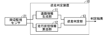
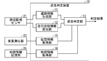
- FIG. 1 is a diagram showing a configuration of a reverse-way driving determination device 10 according to the first embodiment.
- the reverse-way driving determination device 10 is mounted on the vehicle, and hereinafter, the vehicle on which the reverse-way driving determination device 10 is mounted is referred to as "own vehicle".
- the reverse-way driving determination device 10 does not have to be permanently installed in the own vehicle, and may be realized on a portable device such as a mobile phone, a smartphone, or a PND (Portable Navigation Device) that can be brought into the vehicle.
- a part of the reverse-way driving determination device 10 may be realized on a server installed outside the own vehicle and capable of communicating with the reverse-way driving determination device 10.
- the reverse-way driving determination device 10 is connected to the peripheral monitoring sensor 21 mounted on the own vehicle.
- the peripheral monitoring sensor 21 is, for example, a sensor that detects the position and shape of a feature around the own vehicle, and is configured by, for example, a camera, a laser irradiator called LiDAR (Light Detection and Ringing), or a combination thereof.
- the position of the feature detected by the peripheral monitoring sensor 21 is a relative position with respect to the own vehicle, and includes information on the distance and direction from the own vehicle.
- the features detected by the peripheral monitoring sensor 21 are not only three-dimensional objects such as other vehicles and obstacles (guardrails, curbs, gutters, etc.), but also road markings (lane markings, progress) drawn on the road surface. It also includes flat objects such as direction markings) and road shoulders.
- the reverse-way driving determination device 10 includes a road information generation unit 11, a driving state information calculation unit 12, and a reverse-way driving determination unit 13.
- the road information generation unit 11 generates road information, which is information on the road on which the own vehicle is traveling, based on the peripheral information, which is the information acquired by the peripheral monitoring sensor 21 of the own vehicle.
- the road information includes at least information on the position of each lane of the road on which the own vehicle is traveling and information on the normal traveling direction.
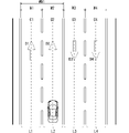
- information on lanes (L1 to L4 in FIG. 3) in road information can be generated by extracting an area between two parallel lane marking lines 51.
- Information on the normal traveling direction of the lane (D1 to D4 in FIG. 3) includes the traveling direction marking 52 (arrow-shaped road marking) drawn on the road surface of the lane and the traveling of another vehicle 53 traveling in the lane. It can be generated based on the direction.
- the road information generation unit 11 clearly allows the vehicle to pass face-to-face due to the type of the lane marking line 51 as the center line of the road (for example, the marking line indicating the prohibition of overtaking for overtaking) or the existence of the median strip. If it can be recognized that the vehicle is traveling on the road, the normal traveling direction of each lane may be determined using the recognition result. That is, the road information generation unit 11 may determine the normal traveling direction of each lane depending on whether the position of the lane is on the left side or the right side of the center line or the median strip.
- the road information may further include information such as the width of the road, the number of lanes, the width of the lane, and the position of the center line of the lane.
- the width of a lane (W1 to W4 in FIG. 3) can be defined as the shortest distance between two lane marking lines 51 sandwiching a lane.
- the center line of the lane (C1 to C4 in FIG. 3) can be defined as a set of points having the same distance from the two lane marking lines 51 sandwiching the lane.
- the number of lanes can be defined as the number of centerlines of the detected lane.
- the width of the road on which the own vehicle is traveling (WW1 in FIG.
- 3) is defined as the width of a range in which lanes having the same normal traveling direction are grouped together (W1 + W2 in FIG. 3). That is, the width of the road on which the own vehicle is traveling (WW1 in FIG. 3) does not include the width of the oncoming lane (W3, W4 in FIG. 3).
- the road information generation unit 11 repeats the generation of road information at a fixed cycle (for example, 30 fps), updates the road information generated in the past with the newly generated road information, or generates the newly generated road information in the past. Add to road information. Further, the road information for which a certain time (for example, 5 seconds) has passed since the update or addition is performed is deleted from the oldest updated or added time.
- a fixed cycle for example, 30 fps
- the running state information calculation unit 12 calculates the running state information, which is the running state information of the own vehicle, based on the peripheral information acquired from the peripheral monitoring sensor 21.
- the traveling state information includes at least information on the position of the own vehicle on the road on which the own vehicle is traveling and information on the traveling direction of the own vehicle. For example, the traveling state information calculation unit 12 acquires the position and the traveling direction when the own vehicle is stopped as the initial position and the initial traveling direction of the own vehicle, and extracts from the surrounding information while the own vehicle is traveling.
- the amount of change in the position of the own vehicle and the amount of change in the traveling direction are calculated at regular intervals, and by integrating them into the initial position and the initial traveling direction of the own vehicle, the current state of the own vehicle is obtained. Calculate the position and direction of travel.
- the reverse-way driving determination unit 13 calculates the reverse-way driving possibility P1 of the own vehicle based on the road information generated by the road information generation unit 11 and the driving state information of the own vehicle calculated by the driving state information calculation unit 12. .. Further, the reverse-way driving determination unit 13 determines whether or not the own vehicle is running in reverse based on the calculated value of the reverse-way driving possibility P1, and outputs the determination result.
- "Wrong-way driving" of a vehicle means that the vehicle travels against the normal direction of travel on the road or lane. Further, in the following description, traveling along the normal traveling direction of the vehicle may be referred to as "forward running".
- the reverse-way driving determination unit 13 determines the lane in which the own vehicle is traveling from the position of each lane included in the road information and the position of the own vehicle included in the traveling state information. Map the position on the lane represented by the road information.
- the road information may include at least information on the position and normal direction of travel of each lane on the road on which the vehicle is traveling, but in addition, the width and center line of each lane. Information such as the position of the vehicle may be included.
- the reverse-way driving determination unit 13 determines the lane in which the own vehicle is traveling by adding information such as the width of each lane and the position of the center line, thereby determining the lane in which the own vehicle is traveling (determination accuracy of the lane in which the own vehicle is traveling. That is, the accuracy of mapping) can be improved.
- the reverse-way driving determination unit 13 calculates the difference between the normal traveling direction of the lane included in the road information and the traveling direction of the own vehicle included in the traveling state information (hereinafter referred to as "direction difference Y"), and the direction difference.
- the reverse run possibility P1 is calculated based on Y.
- the reverse-way driving determination unit 13 calculates the reverse-way driving possibility P1 as 0 when the directional difference Y is less than 90 degrees. Further, the reverse-way driving determination unit 13 sets the reverse-way driving possibility P1 to 0.5 when the directional difference Y is 90 degrees, that is, when the traveling direction of the own vehicle is orthogonal to the normal traveling direction. When the directional difference Y is larger than 90 degrees, the reverse running possibility P1 becomes 1.0 when the directional difference Y is 180 degrees, that is, when the traveling direction in which the own vehicle is traveling and the normal traveling direction are opposite to each other. In addition, the larger the directional difference Y, the greater the possibility of reverse driving P1.
- the rate of increase in P1 may be a fixed value or a value that fluctuates according to the directional difference Y.
- the calculation method of the reverse-way driving possibility P1 is not limited to this, and for example, the reverse-way driving determination unit 13 is based on the inner product of the vector of the normal traveling direction of the lane in which the own vehicle is traveling and the vector of the traveling direction of the own vehicle. , The possibility of reverse running P1 may be calculated.
- the reverse-way driving determination unit 13 determines that the own vehicle is running in reverse when the calculated value of the reverse-way driving possibility P1 exceeds a predetermined threshold value (for example, 0.7).
- the determination result of whether or not the own vehicle is running in reverse is output from the reverse run determination device 10, and for example, a warning device that warns the driver when it is determined that the own vehicle is running in reverse, or the own vehicle. It is used in driving support devices that stop the vehicle in a safe place when it is determined that the vehicle is running in reverse.
- the reverse-way driving possibility P1 is calculated based on the directional difference Y, which is the difference between the normal traveling direction of the lane in which the own vehicle is traveling and the traveling direction of the own vehicle.
- the reliability in the normal traveling direction can be regarded as the reliability N1 of the possibility of reverse driving P1.
- the own vehicle is the sum of the number of the traveling direction indications that the road information generation unit 11 can recognize the direction in the lane in which the own vehicle is traveling and the number of other vehicles that can recognize the traveling direction. It can be regarded as the reliability in the normal traveling direction of the traveling lane, that is, the reliability N1 of the reverse driving possibility P1.
- the reverse-way driving possibility P1 of the own vehicle is calculated without using satellite positioning or map information. Therefore, the calculation accuracy of the reverse-way driving possibility P1 does not depend on the accuracy of satellite positioning or the accuracy of map information, and it is possible to stably and highly accurately determine whether or not the own vehicle is running in reverse. ..
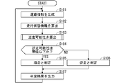
- FIG. 4 is a flowchart showing the operation of the reverse-way driving determination device 10 according to the first embodiment. Hereinafter, the operation of the reverse run determination device 10 will be described with reference to FIG.
- the road information generation unit 11 first generates road information, which is information on the road on which the own vehicle is traveling, based on the peripheral information acquired from the peripheral monitoring sensor 21 of the own vehicle. (Step S101).
- the road information includes at least information on the position of each lane of the road on which the own vehicle is traveling and information on the normal traveling direction.
- the running state information calculation unit 12 calculates the running state information, which is the running state information of the own vehicle, based on the peripheral information (step S102).
- the traveling state information includes at least information on the position of the own vehicle on the road on which the own vehicle is traveling and information on the traveling direction of the own vehicle.
- the reverse-way driving determination unit 13 determines the reverse-way driving possibility P1 of the own vehicle based on the road information generated by the road information generation unit 11 and the driving state information of the own vehicle calculated by the driving state information calculation unit 12. Is calculated (step S103).
- step S103 the reverse-way driving determination unit 13 performs the process shown in FIG. That is, the reverse-way driving determination unit 13 determines the lane in which the own vehicle is traveling from the position of each lane included in the road information and the position of the own vehicle included in the traveling state information, and determines the lane in which the own vehicle is traveling, and the normal traveling direction of the lane and the own vehicle.
- the directional difference Y with the traveling direction of the vehicle is calculated (step S201).
- the reverse-way driving determination unit 13 calculates the reverse-way driving possibility P1 based on the directional difference Y (step S203).
- the reverse-way driving determination unit 13 calculates the reverse-way driving possibility P1 as 0 (step S204).
- the reverse-way driving determination unit 13 confirms whether or not the value of the reverse-way driving possibility P1 calculated in step S103 is equal to or less than a predetermined threshold value (for example, 0.7) (step S104). If the value of the reverse-way driving possibility P1 is equal to or less than the threshold value (YES in step S104), the reverse-way driving determination unit 13 determines that the own vehicle is running forward (step S105). If the value of the reverse-way driving possibility P1 is larger than the threshold value (NO in step S104), the reverse-way driving determination unit 13 determines that the own vehicle is running in reverse (step S106).
- a predetermined threshold value for example, 0.7
- the determination result by the reverse run determination unit 13 is output to the outside (step S107), and then returns to step S101.
- the reverse run determination device 10 repeatedly executes the above operations.
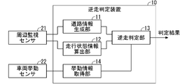
- FIG. 6 is a diagram showing a modified example of the reverse run determination device 10 according to the first embodiment.
- the vehicle behavior sensor 22 is connected to the outside of the reverse-way driving determination device 10 with respect to FIG. 1, and the behavior information acquisition unit 14 is provided in the reverse-way driving determination device 10.
- the vehicle behavior sensor 22 is a sensor for detecting the behavior of the own vehicle, and is, for example, a speed sensor, an acceleration sensor, an orientation sensor, or the like.
- the behavior information acquisition unit 14 acquires behavior information, which is information on the behavior of the own vehicle acquired by the vehicle behavior sensor 22.
- the traveling state information calculation unit 12 cannot calculate the amount of change in the position of the own vehicle and the amount of change in the traveling direction from the peripheral information acquired by the peripheral monitoring sensor 21 (current position and traveling direction of the own vehicle).
- the traveling state information calculation unit 12 calculates the amount of change in the position of the own vehicle and the amount of change in the traveling direction from the behavior information acquired by the behavior information acquisition unit 14.
- the behavior information acquisition is for the purpose of correcting the information.
- the behavior information acquired by the unit 14 may be used.
- the traveling state information calculation unit 12 causes the current position of the own vehicle. And since the traveling direction can be calculated, the reverse driving determination unit 13 can continuously calculate the reverse driving possibility of the own vehicle.
- the turn is considered to be a normal U-turn to the oncoming lane.
- the own vehicle turns from the lane that is not closest to the oncoming lane and the direction of travel is reversed, or if the own vehicle turns to the opposite side of the oncoming lane and the direction of travel is reversed. It is highly likely that the vehicle will run in reverse.
- the reverse-way driving determination unit 13 of the second embodiment determines the lane in which the own vehicle was traveling before turning, the turning direction and turning radius of the own vehicle, and the traveling direction after the own vehicle starts turning.
- the possibility of reverse driving P2 is calculated based on the amount of change (hereinafter, simply referred to as "the amount of change in the traveling direction").
- the turning direction and turning radius of the own vehicle can be calculated based on the position and the traveling direction of the own vehicle included in the traveling state information calculated by the traveling state information calculation unit 12.
- the reverse-way driving determination unit 13 corresponds to the case where the own vehicle turns to the opposite side of the oncoming lane, or the own vehicle turns from the lane that is not closest to the oncoming lane, and the own vehicle
- the turning radius is equal to or less than a predetermined threshold value, it is determined that the own vehicle may run in the reverse direction, and the reverse run possibility P2 is calculated according to the amount of change in the traveling direction of the own vehicle.
- the threshold value of the turning radius is set to half the width of the road on which the own vehicle is traveling.
- the threshold value may be set by any method, for example, the lane farthest from the own vehicle among the lanes that are on the turning direction side of the own vehicle and whose normal traveling direction is the same as the lane in which the own vehicle is traveling. Half of the distance from the lane in which the own vehicle is traveling may be set as the threshold value of the turning radius.
- the reverse running possibility P2 is defined as the ratio of the amount of change in the traveling direction of the own vehicle to a constant angle ⁇ (for example, a fixed value of 120 degrees to 180 degrees). For example, assuming that the constant angle ⁇ is 180 degrees, the possibility of reverse driving P2 is 0.5 when the amount of change in the traveling direction of the own vehicle is 90 degrees.
- the reverse-way driving possibility P2 is for the mileage (2 ⁇ R ⁇ ⁇ / 360) required for the own vehicle to turn by a certain angle ⁇ , which is calculated from the turning radius R at the time when the own vehicle starts turning. It may be defined as the ratio of the mileage after the vehicle starts turning.
- the reverse run determination unit 13 performs the process shown in FIG. 7 in step S103 of the operation flow shown in FIG.
- the reverse-way driving determination unit 13 calculates the turning direction and turning radius of the own vehicle based on the position and the traveling direction of the own vehicle included in the running state information calculated by the running state information calculation unit 12 (step S301). .. At this time, the turning direction of the own vehicle is the direction opposite to the oncoming lane (NO in step S302), and the turning radius of the own vehicle is a predetermined threshold value (the width of the road on which the own vehicle is traveling). If it is less than half) (YES in step S303), the reverse-way driving determination unit 13 determines that the own vehicle may run in the reverse direction, and the reverse-way driving possibility P2 is based on the amount of change in the traveling direction of the own vehicle. Is calculated (step S304).
- the reverse-way driving determination unit 13 determines that the own vehicle may run in the reverse direction, and calculates the reverse-way driving possibility P2 based on the amount of change in the traveling direction of the own vehicle (step S304).
- the reverse-way driving determination unit 13 determines that the own vehicle has made a normal U-turn, and calculates the reverse-way driving possibility P2 as 0 (step S305).
- the reliability of the road width should be regarded as the reliability N2 of the reverse run possibility P2.
- the road edge detection coefficient indicating whether or not the road edge is detected by the road information generation unit 11 is regarded as the reliability N2 of the road width.
- the road edge detection coefficient is 1 when the road information generation unit 11 detects the road edge of the road on which the own vehicle is traveling, and when the road edge is not detected (when there is no road shoulder or the like that originally indicates the road edge). ) Shall take a value of 0.5.
- the reverse-way driving possibility P2 of the own vehicle is calculated without using satellite positioning or map information. Therefore, the calculation accuracy of the reverse-way driving possibility P2 does not depend on the accuracy of satellite positioning or the accuracy of map information, and it is possible to stably and highly accurately determine whether or not the own vehicle is running in reverse. ..
- FIG. 8 is a diagram showing a modified example of the reverse run determination device 10 according to the second embodiment.
- the configuration of FIG. 8 is such that the vehicle behavior sensor 22 is connected to the outside of the reverse-way driving determination device 10 and the behavior information acquisition unit 14 is provided in the reverse-way driving determination device 10 as in FIG. be.
- the behavior information acquired by the vehicle behavior sensor 22 is provided to the reverse-way driving determination unit 13.
- the vehicle behavior sensor 22 is a sensor for detecting the behavior of the own vehicle, and is, for example, a speed sensor, an acceleration sensor, an orientation sensor, or the like.
- the behavior information acquisition unit 14 acquires behavior information, which is information on the behavior of the own vehicle acquired by the vehicle behavior sensor 22.
- the reverse-way driving determination unit 13 if the reverse-way driving determination unit 13 cannot calculate the turning direction and turning radius of the own vehicle from the running state information, the turning direction and turning radius of the own vehicle are obtained from the behavior information acquired by the behavior information acquisition unit 14. Is calculated. Similarly, when the reverse-way driving determination unit 13 cannot calculate the amount of change in the traveling direction of the own vehicle from the traveling state information, the reverse-way driving determination unit 13 calculates the amount of change in the traveling direction of the own vehicle from the behavior information acquired by the behavior information acquisition unit 14. do.
- the reverse driving determination unit 13 acquires behavior information for the purpose of correcting the information.
- the behavior information acquired by the unit 14 may be used.
- the reverse-way driving determination unit 13 can calculate them from the behavior information, so that the own vehicle can run in reverse. Gender can be calculated continuously.
- the reverse run determination unit 13 calculates the reverse run possibility P1 of the first embodiment as the first reverse run possibility, and sets the reverse run possibility P2 of the second embodiment as the second reverse run possibility. It may be calculated and the weighted average of the first reverse-way driving possibility P1 and the second reverse-way driving possibility P2 may be calculated as the final reverse-way driving possibility Pr1 of the own vehicle.
- the weighting of the first reverse run possibility P1 and the second reverse run possibility P2 in the weighted average is the reliability of the first reverse run possibility P1 and the reliability of the second reverse run possibility P2. It may be set based on N2.
- FIG. 9 is a diagram showing the configuration of the reverse run determination device 10 according to the third embodiment.
- the satellite positioning unit 23 and the map information storage unit 24 are connected to the outside of the reverse run determination device 10 with respect to FIG. 1, and the position information acquisition unit 15 and the map information acquisition unit are connected to the reverse run determination device 10. 16 is provided.
- the satellite positioning unit 23 is a means for measuring the position (absolute position) of the own vehicle by satellite positioning using GPS or the like.
- the map information storage unit 24 is a storage medium that stores map information.
- the map information stored in the map information storage unit 24 includes information on the position of each lane (or the position of the lane marking line) on the road and the information in the normal traveling direction of each lane.
- the map information storage unit 24 may be a server installed outside the own vehicle and providing map information to the reverse-way driving determination device 10 by communication.
- the position information acquisition unit 15 acquires information on the position of the own vehicle measured by the satellite positioning unit 23 by satellite positioning and the accuracy of the satellite positioning.
- information on the accuracy of satellite positioning for example, there is DOP (Dilution Of Precision).
- the DOP is an index of the arrangement state of the satellite, and the smaller the value, the higher the positioning accuracy tends to be.
- the map information acquisition unit 16 acquires map information around the position of the own vehicle from the map information storage unit 24.
- the reverse-way driving determination unit 13 uses the same method as that of the first embodiment of the own vehicle.
- the reverse run possibility P1 is calculated and the accuracy of satellite positioning is higher than the threshold value (for example, when the DOP is less than 3)
- the position of the own vehicle acquired by the position information acquisition unit 15 and the map information acquisition unit 16 Based on the acquired map information, the reverse running possibility P3 of the own vehicle is calculated.
- the reverse-way driving determination unit 13 determines whether or not the own vehicle is running in reverse based on the calculated value of the reverse-way driving possibility P1 or P3.
- the reverse travel determination unit 13 is in a state where the accuracy of satellite positioning is higher than the threshold value for a certain period of time (for example, 10 seconds). )
- the reverse running possibility P3 of the own vehicle is calculated based on the position of the own vehicle acquired by the position information acquisition unit 15 and the map information acquired by the map information acquisition unit 16. May be good.
- the method of calculating the reverse-way driving possibility P3 of the own vehicle based on the position (absolute position) of the own vehicle acquired by the position information acquisition unit 15 and the map information acquired by the map information acquisition unit 16 is basically implemented.
- the same method as that of the reverse run possibility P1 of the first embodiment may be used. That is, the reverse-way driving determination unit 13 determines the lane in which the own vehicle is traveling from the position of each lane included in the map information and the absolute position of the own vehicle, so that the position of the own vehicle is on the lane represented by the map information. Map to.
- the reverse-way driving determination unit 13 calculates the difference (direction difference Y) between the normal traveling direction of the lane included in the map information and the traveling direction of the own vehicle, which can be seen from the position change of the own vehicle, and uses the directional difference Y as the difference. Based on this, the possibility of reverse driving P3 is calculated.
- the reverse run possibility P3 also has 0 when the directional difference Y is less than 90 degrees, 0.5 when the directional difference Y is 90 degrees, and the directional difference Y. When it is larger than 90 degrees, it becomes larger as the directional difference Y becomes larger, and it is preferable to calculate so that it becomes 1.0 when the directional difference Y is 180 degrees.
- the reverse run determination device 10 calculates the reverse run possibility P3 of the own vehicle based on the position of the own vehicle measured by the satellite positioning and the map information.
- the reverse running possibility P1 of the own vehicle can be calculated based on the information acquired by the peripheral monitoring sensor 21, so that the determination accuracy of the reverse running possibility can be kept high.
- the third embodiment is also applicable to the first modification of the first embodiment.
- the third embodiment is also applicable to the second embodiment. That is, when the accuracy of satellite positioning is equal to or less than a predetermined threshold value, the reverse run determination unit 13 calculates the reverse run possibility P2 of the own vehicle by the same method as in the second embodiment, and the accuracy of satellite positioning is the threshold value. When it is higher than, the traveling direction and turning radius of the own vehicle are calculated from the change in the position of the own vehicle acquired by the position information acquisition unit 15, and the lane in which the own vehicle was traveling before the turning of the own vehicle and the turning radius of the own vehicle are calculated. And the amount of change in the traveling direction of the own vehicle may be used to calculate the reverse running possibility P4.
- the calculation method of the reverse run possibility P4 may be the same as the calculation method of the reverse run possibility P2 of the second embodiment. That is, the reverse-way driving possibility P4 is defined as the ratio of the amount of change in the traveling direction of the own vehicle to a constant angle ⁇ (for example, a fixed value of 120 degrees to 180 degrees).
- the third embodiment is also applicable to the combination of the first embodiment and the second embodiment (modification example 2 of the second embodiment). That is, when the accuracy of the satellite positioning is equal to or less than a predetermined threshold, the reverse-way driving determination unit 13 calculates the reverse-way driving possibility Pr1 using the above equation (1), and the accuracy of the satellite positioning is higher than the threshold value. Occasionally, the above-mentioned reverse-way driving possibility P3 is calculated as the first reverse-way driving possibility, and the above-mentioned reverse-way driving possibility P4 is calculated as the second reverse-way driving possibility. The weighted average with the second reverse run possibility P4 may be calculated as the final reverse run possibility Pr2 of the own vehicle.
- the weighting of the first reversible possibility P3 and the second reversible possibility P4 in the weighted average is the reliability N3 of the first reversible possibility P3 and the reliability N4 of the second reversible possibility P4. It is good to set based on.
- the reliability N3 corresponding to the reliability of the regular traveling direction of the lane in which the own vehicle is traveling and the reliability of the road width are obtained.
- the reliability N4 corresponding to may be 1 respectively.
- ⁇ Hardware configuration example> 10 and 11 are diagrams showing an example of the hardware configuration of the reverse run determination device 10, respectively.
- Each function of the component of the reverse run determination device 10 shown in FIG. 1 is realized by, for example, the processing circuit 40 shown in FIG. That is, the reverse driving determination device 10 generates road information including information on the position of each lane and the normal traveling direction of the road on which the own vehicle is traveling based on the peripheral information acquired by the peripheral monitoring sensor of the own vehicle, and generates the peripheral information. Based on the information, the driving condition information including the position and the traveling direction information of the own vehicle on the road on which the own vehicle is traveling is calculated, and the reverse running possibility of the own vehicle is calculated based on the road information and the traveling condition information.
- a processing circuit 40 for determining whether or not the own vehicle is running in reverse based on the value of the possibility of reverse running is provided.
- the processing circuit 40 may be dedicated hardware, or may be a processor (Central Processing Unit (CPU), processing unit, arithmetic unit, microprocessor, microprocessor, etc.) that executes a program stored in the memory. It may be configured by using a DSP (also called a Digital Signal Processor).
- CPU Central Processing Unit
- DSP also called a Digital Signal Processor
- the processing circuit 40 may be, for example, a single circuit, a composite circuit, a programmed processor, a parallel programmed processor, an ASIC (Application Specific Integrated Circuit), or an FPGA (Field-Programmable). GateArray), or a combination of these, etc.
- the functions of the components of the reverse-way driving determination device 10 may be realized by individual processing circuits, or these functions may be collectively realized by one processing circuit.
- FIG. 11 shows an example of the hardware configuration of the reverse run determination device 10 when the processing circuit 40 is configured by using the processor 41 that executes the program.
- the function of the component of the reverse-way driving determination device 10 is realized by software (software, firmware, or a combination of software and firmware).
- the software or the like is described as a program and stored in the memory 42.
- the processor 41 realizes the functions of each part by reading and executing the program stored in the memory 42. That is, when the reverse running determination device 10 is executed by the processor 41, the information on the position of each lane and the normal traveling direction of the road on which the own vehicle is traveling is based on the peripheral information acquired by the peripheral monitoring sensor of the own vehicle.
- a program that calculates the reverse running possibility of the own vehicle based on it and determines whether or not the own vehicle is running backward based on the value of the reverse running possibility, and the program that will be executed as a result.
- a memory 42 for storing is provided. In other words, it can be said that this program causes the computer to execute the procedure and method of operation of the components of the reverse-way driving determination device 10.
- the memory 42 is, for example, non-volatile such as RAM (RandomAccessMemory), ROM (ReadOnlyMemory), flash memory, EPROM (ErasableProgrammableReadOnlyMemory), EPROM (ElectricallyErasableProgrammableReadOnlyMemory), or the like. Volatile semiconductor memory, HDD (HardDiskDrive), magnetic disk, flexible disk, optical disk, compact disk, mini disk, DVD (DigitalVersatileDisc) and its drive device, etc., or any storage medium used in the future. You may.
- RAM RandomAccessMemory
- ROM ReadOnlyMemory
- flash memory EPROM (ErasableProgrammableReadOnlyMemory), EPROM (ElectricallyErasableProgrammableReadOnlyMemory), or the like.
- Volatile semiconductor memory Volatile semiconductor memory, HDD (HardDiskDrive), magnetic disk, flexible disk, optical disk, compact disk, mini disk, DVD (DigitalVersatileDisc) and
- the present invention is not limited to this, and a configuration may be configured in which a part of the components of the reverse run determination device 10 is realized by dedicated hardware and another part of the components is realized by software or the like.
- the function is realized by the processing circuit 40 as dedicated hardware, and for some other components, the processing circuit 40 as the processor 41 is stored in the memory 42. It is possible to realize the function by reading and executing it.
- the reverse-way driving determination device 10 can realize each of the above-mentioned functions by hardware, software, or a combination thereof.
Landscapes
- Physics & Mathematics (AREA)
- General Physics & Mathematics (AREA)
- Chemical & Material Sciences (AREA)
- Analytical Chemistry (AREA)
- Engineering & Computer Science (AREA)
- Automation & Control Theory (AREA)
- Mathematical Physics (AREA)
- Transportation (AREA)
- Mechanical Engineering (AREA)
- Traffic Control Systems (AREA)
- Navigation (AREA)
- Control Of Driving Devices And Active Controlling Of Vehicle (AREA)
Abstract
Description
図1は、実施の形態1に係る逆走判定装置10の構成を示す図である。実施の形態1では、逆走判定装置10は車両に搭載されているものとし、以下、逆走判定装置10が搭載された車両を「自車両」という。ただし、逆走判定装置10は自車両に常設される必要はなく、例えば携帯電話やスマートフォン、PND(Portable Navigation Device)など、車両に持ち込み可能な携帯型の装置上に実現されていてもよい。また、逆走判定装置10の一部が、自車両の外部に設置され逆走判定装置10と通信可能なサーバ上に実現されていてもよい。
図6は、実施の形態1に係る逆走判定装置10の変形例を示す図である。図6の構成は、図1に対し、逆走判定装置10の外部に車両挙動センサ22を接続させ、逆走判定装置10内に挙動情報取得部14を設けたものである。
実施の形態2では、逆走判定部13が、衛星測位や地図情報を用いない別の方法により、車両の逆走可能性P2を算出する例を示す。実施の形態2に係る逆走判定装置10の構成および基本動作は、図1および図4と同じであるため、ここでは逆走判定部13が逆走可能性P2を算出する方法のみを説明する。
図8は、実施の形態2に係る逆走判定装置10の変形例を示す図である。図8の構成は、図1に対し、図6と同様に、逆走判定装置10の外部に車両挙動センサ22を接続させ、逆走判定装置10内に挙動情報取得部14を設けたものである。ただし、図6とは異なり、車両挙動センサ22が取得した挙動情報は、逆走判定部13に提供される。
実施の形態1と実施の形態2とは組み合わせ可能である。例えば、逆走判定部13が、第1の逆走可能性として実施の形態1の逆走可能性P1を算出し、第2の逆走可能性として実施の形態2の逆走可能性P2を算出し、第1の逆走可能性P1と第2の逆走可能性P2との加重平均を、最終的な自車両の逆走可能性Pr1として算出してもよい。
Pr1=P1×N1/(N1+N2)+P2×N2/(N1+N2) ・・・(1)
図9は、実施の形態3に係る逆走判定装置10の構成を示す図である。図9の構成は、図1に対し、逆走判定装置10の外部に衛星測位部23および地図情報記憶部24を接続させ、逆走判定装置10内に位置情報取得部15および地図情報取得部16を設けたものである。
実施の形態3は、実施の形態2にも適用可能である。すなわち、逆走判定部13は、衛星測位の精度が予め定められた閾値以下のときには、実施の形態2と同様の方法で自車両の逆走可能性P2を算出し、衛星測位の精度が閾値よりも高いときには、位置情報取得部15が取得した自車両の位置の変化から自車両の進行方向および旋回半径を算出し、自車両が旋回する前に走行していた車線と自車両の旋回半径と自車両の進行方向の変化量とに基づいて逆走可能性P4を算出してもよい。
実施の形態3は、実施の形態1と実施の形態2との組み合わせ(実施の形態2の変形例2)にも適用可能である。すなわち、逆走判定部13は、衛星測位の精度が予め定められた閾値以下のときには、上記の式(1)を用いて逆走可能性Pr1を算出し、衛星測位の精度が閾値よりも高いときには、第1の逆走可能性として上記の逆走可能性P3を算出するとともに、第2の逆走可能性として上記の逆走可能性P4を算出し、第1の逆走可能性P3と第2の逆走可能性P4との加重平均を、最終的な自車両の逆走可能性Pr2として算出してもよい。
Pr2=P3×N3/(N3+N4)+P4×N4/(N3+N4) ・・・(2)
図10および図11は、それぞれ逆走判定装置10のハードウェア構成の例を示す図である。図1に示した逆走判定装置10の構成要素の各機能は、例えば図10に示す処理回路40により実現される。すなわち、逆走判定装置10は、自車両の周辺監視センサが取得した周辺情報に基づき、自車両が走行中の道路の各車線の位置および正規進行方向の情報を含む道路情報を生成し、周辺情報に基づき、自車両が走行中の道路における自車両の位置および進行方向の情報を含む走行状態情報を算出し、道路情報および走行状態情報に基づいて自車両の逆走可能性を算出し、逆走可能性の値に基づいて自車両が逆走しているか否かを判定するための処理回路40を備える。処理回路40は、専用のハードウェアであってもよいし、メモリに格納されたプログラムを実行するプロセッサ(中央処理装置(CPU:Central Processing Unit)、処理装置、演算装置、マイクロプロセッサ、マイクロコンピュータ、DSP(Digital Signal Processor)とも呼ばれる)を用いて構成されていてもよい。
Claims (14)
- 自車両の周辺監視センサが取得した周辺情報に基づき、前記自車両が走行中の道路の各車線の位置および正規進行方向の情報を含む道路情報を生成する道路情報生成部と、
前記周辺情報に基づき、前記自車両が走行中の道路における前記自車両の位置および進行方向の情報を含む走行状態情報を算出する走行状態情報算出部と、
前記道路情報および前記走行状態情報に基づいて前記自車両の逆走可能性を算出し、前記逆走可能性の値に基づいて前記自車両が逆走しているか否かを判定する逆走判定部と、
を備える逆走判定装置。 - 前記逆走判定部は、前記自車両が走行中の車線の正規進行方向と前記自車両の進行方向との差に基づいて前記逆走可能性を算出する、
請求項1に記載の逆走判定装置。 - 前記走行状態情報算出部は、前記周辺情報から前記自車両の位置および進行方向を算出できない場合には、前記自車両の車両挙動センサが取得した情報である挙動情報から前記自車両の位置および進行方向を算出する、
請求項1に記載の逆走判定装置。 - 前記逆走判定部は、前記走行状態情報から前記自車両の旋回方向および旋回半径を算出し、前記自車両が旋回する前に走行していた車線と前記自車両の旋回方向および旋回半径と前記自車両の進行方向の変化量とに基づいて前記逆走可能性を算出する、
請求項1に記載の逆走判定装置。 - 前記逆走判定部は、前記走行状態情報から前記自車両の旋回方向および旋回半径を算出できない場合には、前記自車両の車両挙動センサが取得した情報である挙動情報から前記自車両の旋回方向および旋回半径を算出する、
請求項4に記載の逆走判定装置。 - 前記逆走判定部は、前記走行状態情報から前記自車両の進行方向の変化量を算出できない場合には、前記自車両の車両挙動センサが取得した情報である挙動情報から前記自車両の進行方向の変化量を算出する、
請求項4に記載の逆走判定装置。 - 前記逆走判定部は、前記自車両が走行中の車線の正規進行方向と前記自車両の進行方向との差に基づいて第1の逆走可能性を算出し、前記走行状態情報から前記自車両の旋回方向および旋回半径を算出し、前記自車両が旋回する前に走行していた車線と前記自車両の旋回方向および旋回半径と前記自車両の進行方向の変化量とに基づいて第2の逆走可能性を算出し、前記第1の逆走可能性と前記第2の逆走可能性との加重平均を前記逆走可能性として算出する、
請求項1に記載の逆走判定装置。 - 前記加重平均における前記第1の逆走可能性および前記第2の逆走可能性の重み付けは、前記第1の逆走可能性の信頼度および前記第2の逆走可能性の信頼度に基づいて設定される、
請求項7に記載の逆走判定装置。 - 前記逆走判定部は、前記走行状態情報から前記自車両の旋回方向および旋回半径を算出できない場合には、前記自車両の車両挙動センサが取得した情報である挙動情報から前記自車両の旋回方向および旋回半径を算出する、
請求項7に記載の逆走判定装置。 - 前記逆走判定部は、前記走行状態情報から前記自車両の進行方向の変化量を算出できない場合には、前記自車両の車両挙動センサが取得した情報である挙動情報から前記自車両の進行方向の変化量を算出する、
請求項7に記載の逆走判定装置。 - 衛星測位で測定された前記自車両の位置および前記衛星測位の精度の情報を取得する位置情報取得部と、
地図情報を取得する地図情報取得部と、
をさらに備え、
前記衛星測位の精度が予め定められた閾値より高い場合には、前記逆走判定部は、前記衛星測位で測定された前記自車両の位置と前記地図情報とに基づいて前記自車両の逆走可能性を算出し、前記逆走可能性の値に基づいて前記自車両が逆走しているか否かを判定する、
請求項1に記載の逆走判定装置。 - 前記逆走判定部は、前記逆走可能性が予め定められた閾値を超えると前記自車両が逆走していると判定する、
請求項1に記載の逆走判定装置。 - 前記道路情報には、さらに、各車線の幅および中心線の位置の情報が含まれる、
請求項1に記載の逆走判定装置。 - 逆走判定装置の道路情報生成部が、自車両の周辺監視センサが取得した周辺情報に基づき、前記自車両が走行中の道路の各車線の位置および正規進行方向の情報を含む道路情報を生成し、
前記逆走判定装置の走行状態情報算出部が、前記周辺情報に基づき、前記自車両が走行中の道路における前記自車両の位置および進行方向の情報を含む走行状態情報を算出し、
前記逆走判定装置の逆走判定部が、前記道路情報および前記走行状態情報に基づいて前記自車両の逆走可能性を算出し、前記逆走可能性の値に基づいて前記自車両が逆走しているか否かを判定する、
逆走判定方法。
Priority Applications (5)
| Application Number | Priority Date | Filing Date | Title |
|---|---|---|---|
| US18/029,464 US12620314B2 (en) | 2020-12-10 | Wrong-way driving determination apparatus and wrong-way driving determination method | |
| CN202080107612.4A CN116601690A (zh) | 2020-12-10 | 2020-12-10 | 逆行判定装置及逆行判定方法 |
| DE112020007822.1T DE112020007822T5 (de) | 2020-12-10 | 2020-12-10 | Falschfahrenbestimmungsvorrichtung und falschfahrenbestimmungsverfahren |
| JP2022567961A JP7412598B2 (ja) | 2020-12-10 | 2020-12-10 | 逆走判定装置および逆走判定方法 |
| PCT/JP2020/045976 WO2022123712A1 (ja) | 2020-12-10 | 2020-12-10 | 逆走判定装置および逆走判定方法 |
Applications Claiming Priority (1)
| Application Number | Priority Date | Filing Date | Title |
|---|---|---|---|
| PCT/JP2020/045976 WO2022123712A1 (ja) | 2020-12-10 | 2020-12-10 | 逆走判定装置および逆走判定方法 |
Publications (1)
| Publication Number | Publication Date |
|---|---|
| WO2022123712A1 true WO2022123712A1 (ja) | 2022-06-16 |
Family
ID=81973456
Family Applications (1)
| Application Number | Title | Priority Date | Filing Date |
|---|---|---|---|
| PCT/JP2020/045976 Ceased WO2022123712A1 (ja) | 2020-12-10 | 2020-12-10 | 逆走判定装置および逆走判定方法 |
Country Status (4)
| Country | Link |
|---|---|
| JP (1) | JP7412598B2 (ja) |
| CN (1) | CN116601690A (ja) |
| DE (1) | DE112020007822T5 (ja) |
| WO (1) | WO2022123712A1 (ja) |
Families Citing this family (2)
| Publication number | Priority date | Publication date | Assignee | Title |
|---|---|---|---|---|
| CN117922736B (zh) * | 2024-01-29 | 2024-06-18 | 人民出行(南宁)科技有限公司 | 一种电动车逆行提示警告系统及方法 |
| CN118470987A (zh) * | 2024-04-18 | 2024-08-09 | 北京精英智通科技股份有限公司 | 一种检测车辆行驶方向的方法、装置及电子设备 |
Citations (3)
| Publication number | Priority date | Publication date | Assignee | Title |
|---|---|---|---|---|
| JP2009250964A (ja) * | 2008-04-11 | 2009-10-29 | Toyota Motor Corp | 逆走警告装置、逆走警告方法 |
| JP2012064121A (ja) * | 2010-09-17 | 2012-03-29 | Aisin Aw Co Ltd | 運転支援装置、運転支援方法及びコンピュータプログラム |
| JP2019207454A (ja) * | 2018-05-28 | 2019-12-05 | 有限会社三ッ福 | 逆走警告装置 |
Family Cites Families (4)
| Publication number | Priority date | Publication date | Assignee | Title |
|---|---|---|---|---|
| JP4747963B2 (ja) | 2006-06-21 | 2011-08-17 | トヨタ自動車株式会社 | 車両用運転支援装置 |
| JP2009122825A (ja) | 2007-11-13 | 2009-06-04 | Clarion Co Ltd | 走行状況判定装置 |
| JP2019194756A (ja) | 2018-05-01 | 2019-11-07 | アイシン・エィ・ダブリュ株式会社 | 逆走判定システム、逆走判定方法、及び逆走判定プログラム |
| CN111832376B (zh) * | 2019-07-18 | 2024-08-27 | 北京骑胜科技有限公司 | 一种车辆逆行检测方法、装置、电子设备及存储介质 |
-
2020
- 2020-12-10 CN CN202080107612.4A patent/CN116601690A/zh active Pending
- 2020-12-10 WO PCT/JP2020/045976 patent/WO2022123712A1/ja not_active Ceased
- 2020-12-10 DE DE112020007822.1T patent/DE112020007822T5/de active Pending
- 2020-12-10 JP JP2022567961A patent/JP7412598B2/ja active Active
Patent Citations (3)
| Publication number | Priority date | Publication date | Assignee | Title |
|---|---|---|---|---|
| JP2009250964A (ja) * | 2008-04-11 | 2009-10-29 | Toyota Motor Corp | 逆走警告装置、逆走警告方法 |
| JP2012064121A (ja) * | 2010-09-17 | 2012-03-29 | Aisin Aw Co Ltd | 運転支援装置、運転支援方法及びコンピュータプログラム |
| JP2019207454A (ja) * | 2018-05-28 | 2019-12-05 | 有限会社三ッ福 | 逆走警告装置 |
Also Published As
| Publication number | Publication date |
|---|---|
| US20230360533A1 (en) | 2023-11-09 |
| DE112020007822T5 (de) | 2023-11-02 |
| JPWO2022123712A1 (ja) | 2022-06-16 |
| JP7412598B2 (ja) | 2024-01-12 |
| CN116601690A (zh) | 2023-08-15 |
Similar Documents
| Publication | Publication Date | Title |
|---|---|---|
| US11113544B2 (en) | Method and apparatus providing information for driving vehicle | |
| CN106546977B (zh) | 车辆雷达感知和定位 | |
| JP6410949B2 (ja) | 車線認識装置および車線認識方法 | |
| JP6689966B2 (ja) | 減速縁石に基づく自律走行車の方向検出及び車線維持システム | |
| CN114375467A (zh) | 紧急车辆的检测 | |
| US10782144B2 (en) | Method and apparatus providing information of an autonomous vehicle | |
| CN112534485B (zh) | 前进路线预测装置、计算机可读取记录介质及前进路线预测方法 | |
| US10302754B1 (en) | Object recognition device | |
| US10853667B2 (en) | Method and apparatus with linearity detection | |
| JP5762656B2 (ja) | 車両位置表示制御装置および車両位置特定プログラム | |
| CN111522003A (zh) | 车辆定位方法及系统、计算机设备、车辆、存储介质 | |
| US20220155075A1 (en) | Method and apparatus with localization | |
| JP2015121959A (ja) | 障害物検知装置 | |
| US12420786B2 (en) | Risk estimation system and vehicle control system | |
| CN114287025A (zh) | 行驶辅助方法及行驶辅助装置 | |
| JP2020125988A (ja) | 進入車線推定システム、進入車線推定方法、及び進入車線推定プログラム | |
| WO2019207639A1 (ja) | 行動選択装置、行動選択プログラム及び行動選択方法 | |
| JP7412598B2 (ja) | 逆走判定装置および逆走判定方法 | |
| JP4953015B2 (ja) | 自車位置認識装置と自車位置認識プログラム、及びこれを用いたナビゲーション装置 | |
| JP2018206071A (ja) | 区画線認識装置 | |
| US20250050906A1 (en) | Autonomous Driving Control Apparatus and Method Thereof | |
| JP7209912B2 (ja) | 運転支援制御装置および運転支援制御方法 | |
| US20230086589A1 (en) | Vehicle position estimation device | |
| WO2021033312A1 (ja) | 情報出力装置、自動運転装置、及び、情報出力方法 | |
| WO2020021596A1 (ja) | 車両位置推定装置および車両位置推定方法 |
Legal Events
| Date | Code | Title | Description |
|---|---|---|---|
| 121 | Ep: the epo has been informed by wipo that ep was designated in this application |
Ref document number: 20965095 Country of ref document: EP Kind code of ref document: A1 |
|
| ENP | Entry into the national phase |
Ref document number: 2022567961 Country of ref document: JP Kind code of ref document: A |
|
| WWE | Wipo information: entry into national phase |
Ref document number: 202080107612.4 Country of ref document: CN |
|
| WWE | Wipo information: entry into national phase |
Ref document number: 112020007822 Country of ref document: DE |
|
| 122 | Ep: pct application non-entry in european phase |
Ref document number: 20965095 Country of ref document: EP Kind code of ref document: A1 |