WO2022118940A1 - 車載撮像装置 - Google Patents
車載撮像装置 Download PDFInfo
- Publication number
- WO2022118940A1 WO2022118940A1 PCT/JP2021/044373 JP2021044373W WO2022118940A1 WO 2022118940 A1 WO2022118940 A1 WO 2022118940A1 JP 2021044373 W JP2021044373 W JP 2021044373W WO 2022118940 A1 WO2022118940 A1 WO 2022118940A1
- Authority
- WO
- WIPO (PCT)
- Prior art keywords
- unit
- image
- image pickup
- vehicle
- state
- Prior art date
- Legal status (The legal status is an assumption and is not a legal conclusion. Google has not performed a legal analysis and makes no representation as to the accuracy of the status listed.)
- Ceased
Links
Images



Classifications
-
- B—PERFORMING OPERATIONS; TRANSPORTING
- B60—VEHICLES IN GENERAL
- B60R—VEHICLES, VEHICLE FITTINGS, OR VEHICLE PARTS, NOT OTHERWISE PROVIDED FOR
- B60R11/00—Arrangements for holding or mounting articles, not otherwise provided for
- B60R11/02—Arrangements for holding or mounting articles, not otherwise provided for for radio sets, television sets, telephones, or the like; Arrangement of controls thereof
-
- G—PHYSICS
- G03—PHOTOGRAPHY; CINEMATOGRAPHY; ANALOGOUS TECHNIQUES USING WAVES OTHER THAN OPTICAL WAVES; ELECTROGRAPHY; HOLOGRAPHY
- G03B—APPARATUS OR ARRANGEMENTS FOR TAKING PHOTOGRAPHS OR FOR PROJECTING OR VIEWING THEM; APPARATUS OR ARRANGEMENTS EMPLOYING ANALOGOUS TECHNIQUES USING WAVES OTHER THAN OPTICAL WAVES; ACCESSORIES THEREFOR
- G03B15/00—Special procedures for taking photographs; Apparatus therefor
-
- G—PHYSICS
- G03—PHOTOGRAPHY; CINEMATOGRAPHY; ANALOGOUS TECHNIQUES USING WAVES OTHER THAN OPTICAL WAVES; ELECTROGRAPHY; HOLOGRAPHY
- G03B—APPARATUS OR ARRANGEMENTS FOR TAKING PHOTOGRAPHS OR FOR PROJECTING OR VIEWING THEM; APPARATUS OR ARRANGEMENTS EMPLOYING ANALOGOUS TECHNIQUES USING WAVES OTHER THAN OPTICAL WAVES; ACCESSORIES THEREFOR
- G03B17/00—Details of cameras or camera bodies; Accessories therefor
- G03B17/56—Accessories
-
- G—PHYSICS
- G08—SIGNALLING
- G08G—TRAFFIC CONTROL SYSTEMS
- G08G1/00—Traffic control systems for road vehicles
- G08G1/14—Traffic control systems for road vehicles indicating individual free spaces in parking areas
-
- H—ELECTRICITY
- H04—ELECTRIC COMMUNICATION TECHNIQUE
- H04N—PICTORIAL COMMUNICATION, e.g. TELEVISION
- H04N23/00—Cameras or camera modules comprising electronic image sensors; Control thereof
- H04N23/60—Control of cameras or camera modules
-
- H—ELECTRICITY
- H04—ELECTRIC COMMUNICATION TECHNIQUE
- H04N—PICTORIAL COMMUNICATION, e.g. TELEVISION
- H04N7/00—Television systems
- H04N7/18—Closed-circuit television [CCTV] systems, i.e. systems in which the video signal is not broadcast
Definitions
- the present invention relates to an in-vehicle image pickup device, specifically, an in-vehicle image pickup device capable of reading an image code.
- an image code such as a QR code (registered trademark of Denso Wave Co., Ltd.) may be provided at the entrance / exit gate to grasp the entry / exit of a vehicle into the facility.
- a QR code registered trademark of Denso Wave Co., Ltd.
- an image code is provided on the road surface near the entry gate of an indoor parking lot, and a camera whose imaging direction is fixed to the rear downward is mounted on the vehicle, and the image code of this road surface is used. It is described that the passage of the vehicle's entry gate is grasped by taking an image with a camera.
- the image code is provided on the road surface as described in Patent Document 1, for example, the image code is worn or soiled every time the vehicle passes. In order to prevent such wear and dirt, there is a request to provide an image code on the vehicle side surface of the ticket issuing machine of the entrance / exit gate. When the image code is provided on the surface of the ticket issuing machine in accordance with the request, the image code is located above the road surface.
- the image pickup direction of the camera is fixed to the rear-downward direction as described above, there is a concern that the image code located above the road surface cannot be read.
- an object of the present invention is to provide an in-vehicle image pickup device that is provided above the road surface and can easily read an image code.
- the in-vehicle image pickup apparatus of the present invention has a receiving unit that receives a signal indicating an entrance / exit gate of a predetermined facility, and a first state and an image pickup direction in which the image pickup direction is the direction in which the road surface is imaged.
- An image pickup unit that can switch to a second state in which an image is taken above the road surface, and an image code determination unit that discriminates a predetermined image code from image data captured by the image pickup unit in the second state.
- An image code reading unit that reads information added to the image code from the image code determined by the image code discriminating unit, and a control unit.
- the receiving unit receives the signal. It is characterized in that the image pickup unit is set to the first state when no reception is performed, and the image pickup unit is switched from the first state to the second state when the reception unit receives the signal.
- the in-vehicle image pickup apparatus of the present invention has a receiving unit that receives a signal indicating an entrance / exit gate of a predetermined facility, and a first state in which the viewing angle is adjusted so that the road surface is imaged.
- An image pickup unit capable of switching to a second state in which the viewing angle is wider than the first state, and an image code discrimination unit that discriminates a predetermined image code from image data captured by the image pickup unit in the second state.
- An image code reading unit that reads information added to the image code from the image code determined by the image code discriminating unit, and a control unit.
- the receiving unit receives the signal. It is characterized in that the image pickup unit is set to the first state when no reception is performed, and the image pickup section is switched from the first state to the second state when the reception unit receives the signal.
- the image code refers to an image expressing predetermined identification information, and examples of such an image code include a QR code and a barcode.
- the entry / exit gate means a gate that regulates at least one of entry into the facility of the vehicle and entry from the facility of the vehicle.
- the imaging unit when the receiving unit does not receive the signal indicating the entrance / exit gate, the imaging unit switches to the first state.
- the image pickup unit When the image pickup unit is switched to the first state, the image pickup direction of the image pickup unit is switched to the direction in which the road surface is imaged, and the viewing angle of the image pickup unit is adjusted to image the road surface. Therefore, according to this vehicle-mounted image pickup device, it is possible to image the road surface around the vehicle on which the vehicle-mounted image pickup device is mounted.
- the vehicle equipped with this in-vehicle image pickup device may use the road surface data imaged by the in-vehicle image pickup device as a part of the data for lane departure prevention and automatic driving when the entrance / exit gate is not detected. can.
- the imaging unit when the vehicle approaches the entrance / exit gate to the extent that the receiving unit receives the signal indicating the entrance / exit gate, the imaging unit switches to the second state.
- the image pickup unit switches to the second state, the image pickup direction of the image pickup unit switches to the direction of imaging above the road surface, the viewing angle of the image pickup unit becomes wider than that of the first state, and the image pickup unit moves above the road surface. Take an image. Therefore, according to the in-vehicle image pickup apparatus 1, the image code provided above the road surface can be effectively read as compared with the case where the image pickup direction of the camera is fixed to the rear downward direction.
- the image pickup unit When the image pickup unit can switch between the first state in which the image pickup direction is the direction in which the road surface is imaged and the second state in which the image pickup direction is the direction in which the image pickup direction is above the road surface, the image pickup unit is
- the first state may be a state in which the image pickup direction of the camera faces the road surface
- the second state may be a state in which the image pickup direction of the camera faces upward from the road surface. ..
- the image of the road surface and the reading of the image code provided above the road surface can be performed by one camera. Therefore, the number of cameras constituting the in-vehicle image pickup apparatus can be reduced.
- the image pickup unit when the image pickup unit can switch between the first state in which the image pickup direction is the direction in which the road surface is imaged and the second state in which the image pickup direction is the direction in which the image pickup direction is above the road surface, the image pickup unit is
- the first camera has a first camera whose imaging direction faces the road surface and a second camera whose imaging direction faces above the road surface, and the first state is a state in which the first camera is on and the second camera is off.
- the second state may be a state in which the first camera is off and the second camera is on.
- the drive mechanism for changing the direction of the camera can be omitted.
- the field of view of the image pickup unit is located on the left side or the right side of the vehicle on which the in-vehicle image pickup device is mounted.
- Equipment that manages entry and exit of vehicles to and from facilities such as ticketing machines installed at entrance and exit gates, generally tends to be located on the left or right side of the vehicle. Then, it is assumed that the image code is provided on the vehicle side surface of such equipment. Therefore, by locating the field of view of the image pickup unit on the left side or the right side of the vehicle, the image code can be read more easily when the image code is provided on the vehicle side surface of the equipment.
- control unit may alternately switch between the first state of the image pickup unit and the second state of the image pickup unit while the reception unit receives the signal.
- the in-vehicle imaging device can image the road surface around the entrance / exit gate even when the receiving unit approaches the entrance / exit gate to the extent that the receiving unit receives the signal. Therefore, this in-vehicle image pickup device may be able to drive the vehicle in a state where the lane departure prevention function is activated while reading the image code, or to drive the vehicle by automatic driving.
- the in-vehicle image pickup apparatus further includes an in-vehicle monitor capable of displaying an image captured by the image pickup unit, and the control unit displays the image on the in-vehicle monitor when the image pickup unit is in the second state.
- the image pickup unit When the image pickup unit is in the first state, the image may not be displayed on the in-vehicle monitor.
- the image pickup section captures images above the road surface.
- equipment for managing entry / exit is arranged at the entry / exit gate of a predetermined facility so as to be close to the vehicle. Therefore, by displaying the image captured by the image pickup unit on the in-vehicle monitor when the image pickup unit is in the second state, the driver of the vehicle equipped with the in-vehicle image pickup device is placed close to the vehicle. The equipment can be grasped not only visually but also through the in-vehicle monitor. Therefore, it is possible to prevent the vehicle from coming into contact with the above equipment.
- the in-vehicle monitor is turned off in the first state, the image captured by the image pickup unit is not always displayed on the in-vehicle monitor, and it is possible to suppress the passengers of the vehicle from feeling annoyed.
- the image on the in-vehicle monitor only when the vehicle is close to the entrance / exit gate, it is possible to draw more attention such as contact with the above equipment.
- the in-vehicle image pickup apparatus further includes an illuminance sensor for detecting the illuminance outside the vehicle and a light source for emitting light toward the image pickup target of the image pickup unit in the second state, and the control unit has the illuminance.
- the light source may be made to emit light when a signal indicating that is equal to or less than a predetermined threshold value is input from the illuminance sensor.
- the image pickup target of the image pickup unit in the second state can be illuminated by the light emitted from the light source. Therefore, the image code can be effectively read even when the vehicle is located in a dark part.
- an in-vehicle image pickup device that can easily read an image code provided above the road surface.
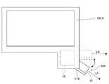
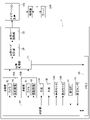
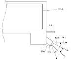
- FIG. 1 It is a schematic diagram which looks at a part of the structure of the vehicle-mounted image pickup apparatus which concerns on 1st Embodiment of this invention from the inside of a vehicle. It is an enlarged view which mainly shows the image pickup part and the right side mirror of a vehicle of the vehicle-mounted image pickup apparatus shown in FIG. 1. It is a block diagram which mainly shows the structure of the vehicle-mounted image pickup apparatus which concerns on 1st Embodiment of this invention. It is a figure which takes a bird's-eye view of an example of a parking lot which is a facility where a vehicle equipped with an in-vehicle image pickup device shown in FIG. 1 is expected to enter and exit.
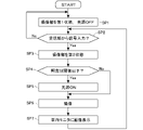
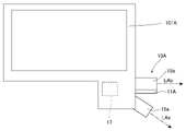
- FIG. 1 It is a front perspective view which shows an example of the entrance gate of the parking lot shown in FIG. It is a flowchart which shows an example of the control flow by the control part of the vehicle-mounted image pickup apparatus shown in FIG. It is a figure which shows mainly the image pickup part of the vehicle-mounted image pickup apparatus which concerns on 2nd Embodiment of this invention from the same viewpoint as FIG. It is a figure which shows mainly the image pickup part of the vehicle-mounted image pickup apparatus which concerns on 3rd Embodiment of this invention from the same viewpoint as FIG.
- FIG. 1 is a schematic view of a part of the configuration of the vehicle-mounted image pickup device according to the present embodiment as viewed from the inside of the vehicle on which the vehicle-mounted image pickup device is mounted.
- FIG. 2 is an enlarged view showing mainly the image pickup unit and the right side mirror of the vehicle of the in-vehicle image pickup apparatus shown in FIG.
- FIG. 3 is a block diagram mainly showing the configuration of the in-vehicle imaging device according to the present embodiment.
- the in-vehicle image pickup apparatus 1 of the present embodiment is mounted on the vehicle 100.
- the vehicle 100 is a right-hand drive vehicle.
- the in-vehicle image pickup device 1 is fixed to the image pickup unit 10A attached to the right side mirror 101A of the vehicle 100, the image pickup unit 10B attached to the left side mirror 101B, the light source 11A fixed to the image pickup unit 10A, and the image pickup unit 10B.
- Light source 11B an in-vehicle monitor 12A attached to the right end of the upper surface of the dashboard 102 of the vehicle 100, an in-vehicle monitor 12B attached to the left end of the upper surface of the dashboard 102, and an in-vehicle monitor 12B attached to a predetermined position on the upper surface of the dashboard 102.
- the receiving unit 13 and the illuminance sensor 14 are included.
- right and left mean right and left with respect to the forward direction of the vehicle 100.
- FIGS. 1 and 2 show an example in which the image pickup units 10A and 10B are attached to the side mirrors 101A and 101B, the attachment positions of the image pickup units 10A and 10B are not limited to the side mirrors.
- the image pickup units 10A and 10B may be attached to, for example, a side door, a front bumper, a rear bumper, or the like of the vehicle 100. Further, the image pickup units 10A and 10B may be configured as a part of the rear view camera.
- the vehicle-mounted image pickup apparatus 1 of the present embodiment further includes a control unit 20, an image processing unit 21, an image code reading unit 22, an image code discriminating unit 24, and a memory 23. ..
- the control unit 20, the image processing unit 21, the image code reading unit 22, and the image code discriminating unit 24 are, for example, a microcontroller, an IC (Integrated Circuit), an LSI (Large-scale Integrated Circuit), and an ASIC (Application Specific Integrated Circuit). It is composed of integrated circuits such as NC (Numerical Control) devices. Further, when an NC device is used, these may be those using a machine learning device or those not using a machine learning device.
- control unit 20 the image processing unit 21, the image code reading unit 22, and the image code discriminating unit 24 may be configured as a part of the ECU (Electronic Control Unit) of the vehicle 100.
- ECU Electronic Control Unit
- at least a part of these may be configured as a part of the navigation device when the navigation device is mounted on the vehicle 100.
- the memory 23 is configured to store information and to be able to read the stored information.
- the memory 23 is, for example, a non-transitory recording medium, and can include a semiconductor recording medium such as a RAM (RandomAccessMemory) or a ROM (ReadOnlyMemory), and the memory 23. May include any type of recording medium such as an optical recording medium or a magnetic recording medium.
- the "non-transient" recording medium includes a recording medium capable of reading all computer signals except for a transient propagation signal (transitory, propagating signal), and excludes volatile recording media. It's not a thing.
- the image pickup unit 10A has one camera 15 and a drive mechanism 16.
- the camera 15 is arranged so that the field of view is located on the right side of the vehicle 100.
- the camera 15 is connected to the control unit 20. Further, the camera 15 includes an image sensor (not shown). Examples of the image pickup device include a CCD (Charge Coupled Device) and a CMOS (Complementary Metal Oxide Semiconductor).
- the image pickup element is connected to the image processing unit 21, converts an image formed on the image pickup element into an analog electric signal through a lens (not shown) of the camera 15, and uses the analog electric signal as an image signal. It is output to the image processing unit 21.
- the drive mechanism 16 is connected to the camera 15 and can move the camera 15 to a predetermined axis center by a predetermined angle.
- FIG. 2 the state of the camera 15 during normal driving on the road is shown by a solid line, and the state of the camera 15 when approaching the entrance / exit gate of a parking lot, which is a predetermined facility to be described later, is shown by a broken line. ing.
- the imaging direction LA of the camera 15 shown by the alternate long and short dash line in FIG. 2 is directed to the lower right during normal driving.
- the imaging direction LA LA is tilted, for example, approximately 45 ° with respect to the vertical direction.
- the angle of inclination is not limited to 45 °.
- the imaging direction LA of the camera 15 is moved upward by approximately 45 ° with respect to the first state and is directed to the right side.
- the angle at which the image pickup direction LA of the camera moves is not limited to 45 °.
- the image pickup unit 10B has the same configuration as the image pickup unit 10A except that the image pickup unit 10B is attached to the left side of the vehicle 100 and the field of view and the image pickup direction are directed to the left side. Therefore, detailed description of the imaging unit 10B will be omitted.
- the drive mechanisms 16 of the image pickup units 10A and 10B are connected to the control unit 20.
- the image pickup units 10A and 10B can switch from one of the first state and the second state to the other.
- FIG. 1 shows an imaging unit 10A in which the imaging direction LA is directed to the right and switched to the second state, and an imaging unit 10B in which the imaging direction LA is directed to the lower left and switched to the first state. ing.
- the light source 11A is a light emitting element that emits light, and may be, for example, a surface mount type LED (Light Emitting Diode). As described above, the light source 11A is fixed to the image pickup unit 10A, and the optical axis of the light source 11A faces the same direction as the image pickup direction LA of the camera 15. Therefore, the light source 11A can move with the movement of the camera 15 to emit light toward the image pickup target of the image pickup unit 10A. Since the light source 11B has the same configuration as the light source 11A except that it is attached to the left side of the vehicle, detailed description of the light source 11B will be omitted.
- a surface mount type LED Light Emitting Diode
- Each of the light sources 11A and 11B is connected to the control unit 20 and emits light based on the control signal from the control unit 20.
- the in-vehicle monitors 12A and 12B each have the same configuration, and may be, for example, a liquid crystal display.
- the in-vehicle monitor 12A is connected to the image pickup unit 10A via the control unit 20, and the in-vehicle monitor 12B is connected to the image pickup unit 10B via the control unit 20.
- the in-vehicle monitors 12A and 12B display an image based on an image signal input from each of the image pickup units 10A and 10B via the control unit 20.
- the positions of the in-vehicle monitors 12A and 12B are not limited to the above, and may be included in, for example, a monitor built in the instrument panel or a monitor of a navigation device.
- the receiving unit 13 includes a receiver that receives a predetermined electromagnetic wave, and receives the electromagnetic wave transmitted by the signal transmitting unit installed at the entrance / exit gate of the predetermined facility.
- This electromagnetic wave is a signal indicating an entrance / exit gate of a predetermined facility, and examples of such an electromagnetic wave include radio waves in the 5.8 GHz band and 2.4 GHz band, infrared rays, and the like.
- the receiver When the electromagnetic wave received by the receiving unit 13 is a radio wave, the receiver may be composed of an antenna, and when the electromagnetic wave received by the receiving unit 13 is an infrared ray, the receiver may be composed of a photodiode. ..
- the receiving unit 13 is connected to the control unit 20, and when it receives a signal indicating an entry / exit gate of a predetermined facility, it outputs the signal to the control unit 20.
- the illuminance sensor 14 is a sensor that detects the illuminance outside the vehicle. Examples of such an illuminance sensor 14 include a photodiode, an element in which an amplifier circuit is added to the photodiode, a phototransistor, and the like.
- the illuminance sensor 14 is connected to the control unit 20, detects the illuminance of the light illuminating the upper surface of the dashboard 102 of the vehicle 100, and outputs a signal indicating the illuminance to the control unit 20.
- the image processing unit 21 is connected to the image pickup unit 10A, the image pickup section 10B, the image code discrimination section 24, and the memory 23.
- the image processing unit 21 converts the analog electric signal into a digital electric signal. Further, the image processing unit 21 performs various processing such as color development determination, white balance processing, contour processing, and noise removal based on the digital electric signal, and stores the processed image data in the memory 23. .. Further, the image processing unit 21 outputs the image data to the image code determination unit 24.
- the image code discriminating unit 24 is connected to the image code reading unit 22.
- the image code determination unit 24 determines whether or not a predetermined image code is included in the image data input from the image processing unit 21.
- the image code discriminating unit 24 outputs the discriminated image code data to the image code reading unit 22.
- the image code reading unit 22 When the image code data is input from the image code discriminating unit 24, the image code reading unit 22 performs decoding processing on the data. As a result, the image code reading unit 22 can read the information given to the image code included in the image captured by the image pickup unit 10A and the image pickup unit 10B. Examples of the information given to this image code include data specifying a predetermined facility and data on entry / exit time to the predetermined facility. Further, in the present embodiment, the image code reading unit 22 is connected to the navigation device 105 of the vehicle 100, and outputs the information given to the image code to the navigation device 105.
- the navigation device 105 is wirelessly connected to a terminal 2 such as a mobile phone or a smartphone owned by the driver of the vehicle 100.
- a terminal 2 such as a mobile phone or a smartphone owned by the driver of the vehicle 100.
- Examples of this wireless communication include Bluetooth (Bluetooth) (registered trademark) communication. Therefore, the information given to the image code transmitted to the navigation device 105 is transmitted to the terminal 2 via the wireless communication.
- the terminal 2 stores data that identifies the vehicle 100, such as the number of the vehicle 100.
- an application for online settlement of parking fees is installed in the terminal 2 for a business operator who manages a parking lot, which is a predetermined facility.
- This application transmits data for specifying the vehicle 100, data for specifying the parking lot, and data for the entry / exit time to the parking lot to the server 230 of the above-mentioned business operator, and also receives settlement data from the server 230. It is configured to allow online payment.
- the server 230 calculates the charge charged for the vehicle 100 based on the data for specifying the vehicle 100, the data for specifying the parking lot, and the data of the entry / exit time to the parking lot, and this settlement data. Is transmitted to the terminal 2.
- the memory 23 is connected to the control unit 20 and the image processing unit 21.
- the memory 23 temporarily stores the image data transmitted from the image processing unit 21. Further, each time the image data is sequentially input from the image processing unit 21, the memory 23 erases the old image data and saves the latest image data. Further, the control unit 20 reads the image data from the memory 23 and outputs the image signals indicating the image data to the in-vehicle monitors 12A and 12B.
- a parking lot which is a predetermined facility where a vehicle 100 equipped with an in-vehicle image pickup device 1 is expected to enter and exit, will be described.
- the mode of the predetermined facility is not limited to the following description.
- FIG. 4 is a bird's-eye view of the parking lot 200.
- the parking lot 200 is connected to the road Ro.
- the parking lot 200 is a parking area 203, an entrance gate 201 among the entrance / exit gates that are passages from the road Ro to the parking area 203, and an entrance / exit gate that is a passage from the parking area 203 to the road Ro. Includes gate 202 and.
- FIG. 5 is a front perspective view showing the entrance gate 201.
- the entrance gate 201 left and right the introduction road 210 connecting the road Ro and the parking area 203, the gate main body 211 erected across the introduction road 210, and the introduction road 210. It has a pair of ticketing machines 212 and an entrance bar 213.
- the gate main body 211 is arranged at a position close to the road Ro
- the entrance bar 213 is arranged at a position close to the parking area 203
- the ticket issuing machine 212 is located between the gate main body 211 and the entrance bar 213. Is located in.
- the positional relationship between the gate body 211, the ticket issuing machine 212, and the entrance bar 213 is not limited to this.
- a signal transmission unit 215 is provided at a portion of the gate main body 211 facing the introduction path 210.
- a predetermined electromagnetic wave is transmitted from the signal transmission unit 215 toward the introduction path 210 side.
- the propagation range TA1 of this electromagnetic wave is shown by a broken line.
- the propagation range TA1 extends in a circle around the signal transmission unit 215 in a top view, covers almost the entire area of the entrance gate 201, but does not reach the road Ro or the parking area 203.
- the receiving unit 13 receives the electromagnetic wave and outputs a signal indicating the entrance gate 201 of the parking lot 200 to the control unit 20.
- the ticketing machine 212 is provided with a ticketing unit 212D for issuing a parking ticket.
- the ticketing unit 212D is provided with a display, and a predetermined image code is displayed on the display.
- This image code represents predetermined identification information as an image, and may be, for example, a QR code or a barcode.
- the image code is provided with information for identifying the parking lot 200 and information for the current time.
- 1440 image codes 24 (hours) ⁇ 60 (minutes) in which the portions representing the times are different from each other are sequentially displayed on the display of the ticket issuing unit 212D every minute.
- the entrance bar 213 is connected to the server 230 (see FIG. 3) of the business operator that manages the parking lot 200 by a communication network.
- the ECU of the vehicle 100 may generate information in which the image code and the time when the image code is read are linked. This also applies to the image code displayed on the ticketing unit 222D described later of the entry gate 202.
- the entry gate 202 sandwiches the lead-out path 220 connecting the parking area 203 and the road Ro, the gate main body 221 erected across the lead-out path 220, and the lead-out path 220 on the left and right. It has a pair of ticketing machines 222 and a participation bar 223.
- the gate body 221 is arranged near the parking area 203
- the entry bar 223 is arranged near the road Ro
- the ticketing machine 222 is located between the gate body 221 and the entry bar 223. Is located in.
- the positional relationship between the gate body 221 and the ticket issuing machine 222 and the entry bar 223 is not limited to this.
- a signal transmission unit 225 is provided at a portion of the gate body 221 facing the lead-out path 220, similarly to the signal transmission unit 215 of the gate body 211.
- a predetermined electromagnetic wave is transmitted from the signal transmission unit 225 toward the lead-out path 220 side.
- the propagation range TA2 of this electromagnetic wave is shown by a broken line.
- the propagation range TA2 extends in a circle around the signal transmission unit 225 in a top view, covers almost the entire area of the entry gate 202, but does not reach the road Ro or the parking area 203.
- the receiving unit 13 receives the electromagnetic wave and outputs a signal indicating the entry gate 202 of the parking lot 200 to the control unit 20.
- the ticketing machine 222 is provided with a ticketing unit 222D for issuing a parking ticket.
- the ticketing unit 222D is provided with a display, and a predetermined image code is displayed on the display.
- This image code may be, for example, a QR code or a barcode.
- the image code is provided with information for identifying the parking lot 200 and information on the time when the vehicle 100 passes through the entry gate 202.
- 1440 image codes 24 (hours) ⁇ 60 (minutes) in which the portions representing the times are different from each other are sequentially displayed on the display of the ticket issuing unit 222D every minute. As a result, the time corresponding to the image code is read.
- the entry bar 223 is connected to the server 230 (see FIG. 3) of the operator that manages the parking lot 200 by a communication network.
- FIG. 6 is a diagram showing an example of a control flow by the control unit 20 of the vehicle-mounted image pickup device 1.
- the control flow by the control unit 20 is not limited to this.
- the control flow of the control unit 20 in the present embodiment includes steps SP1 to SP7.
- the control by the control unit 20 starts when the ignition power of the vehicle 100 is turned on.
- the image pickup units 10A and 10B are in the first state
- the light sources 11A and 11B are in the off state
- the illuminance sensor 14 outputs a signal indicating the illuminance to the control unit 20.
- Step SP1 When the ignition power is turned on, the control unit 20 maintains the first state of the image pickup units 10A and 10B, and maintains the off state of the light sources 11A and 11B. At the stage of this step SP1, the vehicle 100 exists at a position away from the parking lot 200, and the receiving unit 13 does not receive the electromagnetic waves from the signal transmitting units 215 and 225. Then, the control unit 20 advances the control flow to step SP2.
- control unit 20 sets the image pickup units 10A and 10B in the first state and the light sources 11A and 11B in the off state to control the flow. To step SP2.
- Step SP2 After step SP1, while the vehicle 100 travels, for example, at a position away from the parking lot 200, the electromagnetic waves from the signal transmission units 215 and 225 do not reach the vehicle 100. Therefore, the receiving unit 13 does not receive the electromagnetic wave from the signal transmitting units 215 and 225. When the receiving unit 13 does not receive the electromagnetic wave, no signal is input from the receiving unit 13 to the control unit 20, and the control unit 20 returns the control flow to step SP1. In this way, the first state of the imaging units 10A and 10B is maintained. The image data of the road surface captured by the image pickup units 10A and 10B is sent to the image processing unit 21 for image processing, and is repeatedly stored and updated in the memory 23. In this way, while the vehicle 100 travels at a position away from the parking lot 200, the vehicle 100 travels in a state where the lane departure prevention function is activated or automatically operates based on the image data of the road surface. obtain.
- control unit 20 may or may not display the image of the road surface captured by the image pickup units 10A and 10B on the in-vehicle monitors 12A and 12B. In the present embodiment, the control unit 20 does not display the image of the road surface imaged by the image pickup units 10A and 10B on the in-vehicle monitors 12A and 12B when the image pickup units 10A and 10B are in the first state. However, the control unit 20 may display alert information and the like that contribute to driving support on the in-vehicle monitors 12A and 12B when the image pickup units 10A and 10B are in the first state.
- the control unit 20 may use the in-vehicle monitors 12A and 12B. May display alert information indicating the presence of the moving object.
- the vehicle 100 when the vehicle 100 enters the entrance gate 201 of the parking lot 200 from the road Ro, the vehicle 100 enters the propagation range TA1 of the electromagnetic wave from the signal transmitting unit 215, and the receiving unit 13 enters the electromagnetic wave. To receive. Upon receiving the electromagnetic wave, the receiving unit 13 outputs a signal indicating the entrance gate 201 of the parking lot 200 to the control unit 20. When this signal is input, the control unit 20 advances the control flow to step SP3.
- Step SP3 since the vehicle 100 is a right-hand drive vehicle, the control unit 20 outputs a control signal to the image pickup unit 10A.
- the drive mechanism 16 When a control signal is input to the image pickup unit 10A, the drive mechanism 16 operates to switch the image pickup unit 10A from the first state to the second state.
- the image pickup direction LA of the camera 15 of the image pickup unit 10A is directed above the road surface, and the image pickup unit 10A can image the right side of the vehicle 100 above the road surface of the vehicle 100.
- the image pickup unit 10A can image the image code displayed on the ticketing unit 212D of the ticketing machine 212 located on the right side of the vehicle 100.
- the control unit 20 does not switch the image pickup unit 10B located on the left side to the second state. This is because the vehicle 100 is a right-hand drive vehicle as described above, so that the driver can easily bring the vehicle 100 closer to the ticketing machine 212 on the right side, and as a result, the image code displayed on the ticketing machine 212 on the right side is captured by the image pickup unit. The reason is that it is easy to fit in the camera 15 of 10A. From this point of view, when the vehicle 100 is a left-hand drive vehicle, the control unit 20 may switch only the image pickup unit 10B to the second state. However, the control unit 20 may switch both the image pickup units 10A and 10B to the second state. The control unit 20 switches the image pickup unit 10A to the second state, and then advances the control flow to step SP4.
- Step SP4 In this step, when the signal input from the illuminance sensor 14 shows illuminance equal to or less than a predetermined threshold value, the control unit 20 advances the control flow to step SP5. On the other hand, when the signal input from the illuminance sensor 14 shows an illuminance larger than a predetermined threshold value, the control unit 20 advances the control flow to step SP6.
- Step SP5 the control unit 20 outputs a control signal to the light source 11A fixed to the image pickup unit 10A, turns on the light source 11A, and causes the light source 11A to emit light. In this way, light is emitted from the light source 11A toward the image pickup target of the image pickup unit 10A in the second state.
- the image pickup unit 10A can clearly image the image code provided in the ticketing unit 212D as compared with the case where the light source 11A does not emit light.
- the control unit 20 advances the control flow to step SP6.
- Step SP6 the control unit 20 outputs a control signal to the image pickup unit 10A.
- the image pickup unit 10A images the outside view on the right side of the vehicle 100.
- a ticketing unit 212D of the ticketing machine 212 is arranged on the right side of the vehicle 100, and as described above, an image code is displayed on the ticketing unit 212D. Therefore, the image pickup unit 10A can capture an image including the image code.
- the control unit 20 advances the control flow to step SP7.
- the image data captured by the image pickup unit 10A in the second state is input to the image processing unit 21 as described above, and the image processing unit 21 performs image processing.
- This image-processed data is stored in the memory 23.
- an image code is extracted by the image processing unit 21 in the process of the image processing, and the data of the extracted image code is input to the image code reading unit 22.
- the image code data is decoded by the image code reading unit 22, and the information added to the image code is extracted. As described above, this information is data for identifying the parking lot 200 and data for the time when the vehicle 100 passes through the entrance gate 201. Then, as shown in FIG. 3, these data are sent from the image processing unit 21 to the navigation device 105, and are sent to the terminal 2 owned by the driver via wireless communication.
- the above-mentioned application of the terminal 2 operates, and the data for specifying the parking lot 200, the data for the time when the vehicle 100 passes through the entrance gate 201, and the data for specifying the vehicle 100 are stored in the server 230 of the operator. Will be sent to.
- the server 230 enters the parking lot 200 of the vehicle 100. Judge that it is finished. Then, the server 230 outputs a control signal to the entrance bar 213 of the entrance gate 201, and the entrance bar 213 opens based on this control signal.
- the vehicle 100 can enter the parking area 203.
- the server 230 stores the data specifying the parking lot 200, the data at the time when the vehicle 100 has passed the entrance gate 201, and the data specifying the vehicle 100 in the memory connected to the server 230.
- Step SP7 the control unit 20 reads the image data captured in step SP6 from the memory 23, and displays the image related to the image data on the in-vehicle monitor 12A.
- the driver of the vehicle 100 can recognize the ticketing machine 212 or the like located on the right side of the vehicle 100 on the in-vehicle monitor 12A, and the vehicle 100 is suppressed from coming into contact with the ticketing machine 212 or the like.
- the control unit 20 returns the control flow to step SP2.
- the vehicle 100 When the entrance bar 213 opens and the vehicle 100 reaches the parking area 203 as described above, the vehicle 100 is located outside the propagation range TA1 and TA2. Therefore, the receiving unit 13 does not receive the electromagnetic wave transmitted from the signal transmitting units 215 and 225. Further, when the vehicle 100 reaches the parking area 203, the control flow returns from step SP7 to step SP2, and when the receiving unit 13 does not receive the electromagnetic wave, the control unit 20 returns the control flow to step SP1. When the vehicle 100 stops at the parking area 203 and the ignition power is turned off, the control flow of steps SP1 to SP7 is temporarily interrupted.
- the control flow of steps SP1 to SP7 is started again. Therefore, when the vehicle 100 approaches the entry gate 202 to exit the parking lot 200 and enters the propagation range TA2, a signal is input from the reception unit 13 to the control unit 20.
- the control unit 20 switches the image pickup unit 10A from the first state to the second state based on this signal.
- the image code displayed on the ticketing unit 222D of the ticketing machine 222 at the entry gate 202 is imaged by the image pickup unit 10A.
- the captured image code is image-processed by the image processing unit 21 as described above, then decoded by the image code reading unit 22, and the data specifying the parking lot 200 and the time when the vehicle 100 passes through the entry gate 202. Data is read.
- the server 230 transmits a control signal to the entry bar 223.
- the entry bar 223 is opened by this control signal, and the vehicle 100 can leave the parking lot 200.
- the control unit 20 switches the image pickup unit 10A from the second state to the first state.
- the server 230 transmits the parking fee data to the terminal 2.
- the above-mentioned application of the terminal 2 operates, and the parking fee is settled online.
- the in-vehicle image pickup apparatus 1 of the present embodiment includes a reception unit 13 that receives signals indicating the entrance / exit gates 201 and 202, an image pickup unit 10A that can switch between the first state and the second state, and an image pickup unit 10A.
- Information given to the image code is read from the image code discriminating unit 24 that discriminates a predetermined image code from the image data captured by the image capturing unit 10A in the second state and the image code determined by the image code discriminating unit 24.
- An image code reading unit 22 and a control unit 20 are provided.
- the control unit 20 sets the image pickup unit 10A in the first state when the reception unit 13 does not receive the signal, and switches the image pickup unit 10A from the first state to the second state when the reception unit 13 receives the signal.
- the image pickup section 10A switches to the first state.
- the image pickup direction of the image pickup unit 10A is switched to the direction in which the road surface is imaged. Therefore, according to the vehicle-mounted image pickup device 1, the road surface around the vehicle 100 on which the vehicle-mounted image pickup device 1 is mounted can be imaged. Further, when the entrance / exit gates 201 and 202 are not detected, the vehicle 100 can use the road surface data imaged by the vehicle-mounted image pickup device 1 as data for lane departure prevention and automatic driving.
- the image pickup unit 10A switches to the second state. ..
- the image pickup direction of the image pickup unit 10A is switched to the direction of imaging above the road surface, and the image pickup unit 10A images the image above the road surface. Therefore, according to the in-vehicle image pickup apparatus 1, the image code provided above the road surface can be effectively read as compared with the case where the image pickup direction of the camera 15 is fixed to the rear-downward direction, for example.
- the image pickup unit 10A has one camera 15, the first state is a state in which the image pickup direction of the camera 15 faces the road surface, and the second state is a state in which the image pickup direction of the camera 15 faces the road surface.
- the image pickup direction of the camera 15 is in a state of facing upward from the road surface.
- the field of view of the image pickup unit 10A is located on the right side of the vehicle 100
- the field of view of the image pickup unit 10B is located on the left side of the vehicle 100.
- Equipment that manages entry and exit of the vehicle 100 into and out of the facility such as the ticketing machines 212 and 222 provided at the entry / exit gates 201 and 202, generally tends to be located on the left or right side of the vehicle 100.
- the image code is provided on the vehicle side surface of such equipment. Therefore, by locating the field of view of the image pickup unit on the left side or the right side of the vehicle 100, the image code can be more easily read when the image code is provided on the vehicle side surface of the equipment.
- the in-vehicle image pickup apparatus 1 of the present embodiment further includes an in-vehicle monitor 12A capable of displaying an image captured by the image pickup unit 10A.
- the control unit 20 causes the in-vehicle monitor 12A to display an image when the image pickup unit 10A is in the second state, and does not display the image on the in-vehicle monitor 12A when the image pickup unit 10A is in the first state.
- the driver of the vehicle 100 not only visually recognizes the ticketing machines 212, 222 and the like but also through the in-vehicle monitor 12A. Can be grasped.
- the in-vehicle monitor 12A is turned off in the first state, the image captured by the image pickup unit 10A is not always displayed on the in-vehicle monitor 12A, and the passenger of the vehicle 100 is prevented from feeling annoyed. Can be done. Further, by displaying the image on the in-vehicle monitor 12A only when the entrance / exit gates 201 and 202 are close to each other, it is possible to draw more attention such as contact with the ticket issuing machines 212 and 222.
- the control unit 20 causes the light source 11A to emit light when a signal indicating that the illuminance is equal to or less than a predetermined threshold value is input from the illuminance sensor 14.
- the image pickup target of the image pickup unit 10A in the second state can be illuminated by the light emitted from the light source 11A. Therefore, the vehicle-mounted image pickup device 1 can effectively read the image code even when the vehicle 100 is located in a dark part.
- FIG. 7 is a diagram showing mainly the image pickup unit 10A of the vehicle-mounted image pickup apparatus 1 according to the present embodiment from the same viewpoint as that of FIG.
- the image pickup unit 10B of the present embodiment has the same configuration as the image pickup unit 10A of the present embodiment except for a point attached to the left side of the vehicle 100 and a point where the field of view and the image pickup direction face the left side.
- the vehicle-mounted image pickup device 1 according to the present embodiment has the same configuration as the vehicle-mounted image pickup device 1 according to the first embodiment, except that the configurations of the image pickup units 10A and 10B are different. Therefore, the configuration of the imaging unit 10A will be mainly described below.
- the image pickup unit 10A has two cameras, a first camera 15a and a second camera 15b, and a switch circuit 17.
- the image pickup unit 10A of the present embodiment is different from the image pickup unit 10A of the first embodiment composed of one camera 15.
- the first camera 15a and the second camera 15b are both cameras having a fixed focal length.
- the imaging direction LAa of the first camera 15a is directed to the lower right, and is tilted by, for example, approximately 45 ° with respect to the vertical direction.
- the angle of inclination is not limited to 45 °.
- the switch circuit 17 is connected to the first camera 15a, the second camera 15b, and the control unit 20.
- the control unit 20 outputs the first control signal to the switch circuit 17 in step SP1 described above.
- the first control signal may have a voltage smaller than, for example, a predetermined threshold value.
- the switch circuit 17 turns on the first camera 15a and turns off the second camera 15b while the first control signal is input. In this way, during normal driving, the image pickup unit 10A is in the first state in which the image pickup direction is the direction in which the road surface is imaged.
- the control unit 20 inputs the second control signal to the switch circuit 17 in the above-mentioned step SP3.
- the second control signal may be, for example, a voltage equal to or higher than the predetermined threshold value.
- the switch circuit 17 turns off the first camera 15a and turns on the second camera 15b while the second control signal is input.
- the image pickup unit 10A when the vehicle 100 approaches the entrance / exit gates 201 and 202 of the parking lot 200, the image pickup unit 10A is in the second state in which the image pickup direction is the direction in which the image pickup direction is above the road surface. Switch to.
- the light source 11A is fixed to the second camera 15b. Therefore, as in the first embodiment, the control unit 20 can effectively read the image code even when the vehicle 100 is located in the dark part by executing the steps SP4 and SP5.
- the light source 11A may be further attached to the first camera 15a.
- the image pickup unit 10A has a first camera 15a in which the image pickup direction LAa faces the road surface and a second camera 15b in which the image pickup direction LAb faces above the road surface.
- the first camera 15a is on and the second camera 15b is off
- the first camera 15a is off and the second camera 15b is on.
- FIG. 8 is a diagram showing mainly the image pickup unit 10A of the vehicle-mounted image pickup apparatus 1 according to the present embodiment from the same viewpoint as that of FIG.
- the image pickup unit 10B of the present embodiment has the same configuration as the image pickup unit 10A of the present embodiment except for a point attached to the left side of the vehicle 100 and a point where the field of view and the image pickup direction face the left side.
- the vehicle-mounted image pickup device 1 according to the present embodiment has the same configuration as the vehicle-mounted image pickup device 1 according to the first embodiment, except that the configurations of the image pickup units 10A and 10B are different. Therefore, the configuration of the imaging unit 10A will be mainly described below.
- the image pickup unit 10A has one camera 15c.
- the camera 15c has a wide-angle lens whose focal length can be changed. Therefore, since the focal length of the wide-angle lens is relatively long, the viewing angle of the camera 15c is narrowed, and the image pickup unit 10A is in the first state having the narrow field of view FA1 shown by the solid line in FIG. On the other hand, since the focal length of the wide-angle lens of the camera 15c is relatively shortened, the viewing angle of the camera 15c is widened, and the image pickup unit 10A is in the second state having the field of view FA2 wider than the field of view FA1. In FIG. 8, this visual field FA2 is shown by a chain double-dashed line.
- the visual field FA1 is included in the visual field FA2, and in the present embodiment, the visual field FA1 is a range substantially in the center of the visual field FA2.
- the narrow field of view FA1 is used, so that the road surface located at the lower right of the vehicle 100 is mainly imaged.
- the viewing angle is adjusted so that the road surface is imaged.
- the field of view FA2 is wider than the field of view FA1, so that the region on the right side above the road surface is imaged.
- control unit 20 is connected to the image pickup unit 10A.
- the control unit 20 puts the image pickup unit 10A in the first state in step SP1 described above. Further, when the signal indicating the entrance gate 201 of the parking lot 200 is input from the receiving unit 13 in the above-mentioned step SP2, the control unit 20 switches the imaging unit 10A to the second state by the above-mentioned step SP3.
- the image pickup unit 10A can image the area on the right side above the road surface, and can image the image code or the like provided in the ticketing unit 212D of the ticket issuing machine 212. ..
- the light source 11A is attached above the position where the image pickup unit 10A is attached in the right side mirror 101A with the optical axis directed to the right side.
- the light source 11A can emit light toward, for example, an image code, which is an image pickup target of the image pickup unit 10A in the second state. Therefore, as in the first embodiment, the control unit 20 can effectively read the image code even when the vehicle 100 is located in the dark part by executing the steps SP4 and SP5.
- the light source 11A may be attached to the first camera 15a.
- the vehicle-mounted image pickup device 1 of the present embodiment can switch between a first state in which the viewing angle is adjusted so that the road surface is imaged and a second state in which the viewing angle is wider than the first state.
- the image pickup unit 10A is provided. According to this configuration, when the entry / exit gates 201 and 202 are not detected, the vehicle-mounted image pickup device 1 travels on the vehicle 100 with the lane departure prevention function activated based on the road surface data captured by the vehicle-mounted image pickup device 1. The vehicle 100 can be driven or automatically driven. Further, when the vehicle 100 approaches the entry / exit gates 201 and 202 to the extent that the reception unit 13 receives the signal indicating the entry / exit gates 201 and 202, the image pickup unit 10A switches to the second state.
- the in-vehicle image pickup apparatus 1 can effectively read the image code provided above the road surface, as compared with the case where the image pickup direction of the camera 15 is fixed to the rear-downward direction, for example.
- the control unit 20 alternately switches between the first state of the imaging unit 10A and the second state of the imaging unit 10A while the receiving unit 13 receives the signals indicating the entrance / exit gates 201 and 202 of the predetermined facility. May be good.
- the control unit 20 switches the image pickup unit 10A to the second state, then switches the image pickup unit 10A to the first state after a predetermined time elapses, and then again after a predetermined time elapses.
- the cycle of switching to two states may be repeated. In this way, during the period in which the receiving unit 13 receives the signals indicating the entry / exit gates 201 and 202, the control unit 20 alternately switches between the first state and the second state.
- the vehicle-mounted image pickup apparatus 1 can image the road surface around the entrance / exit gates 201 and 202 even when the receiving unit 13 approaches the entrance / exit gates 201 and 202 to such an extent that the receiving unit 13 receives the signal. Therefore, the vehicle-mounted image pickup device 1 may be able to drive the vehicle 100 in a state where the lane departure prevention function is activated while reading the image code, or to drive the vehicle 100 by automatic driving.
- the second state and the first state are displayed while the receiving unit 13 receives the signals indicating the entrance / exit gates 201 and 202.
- the image of the second state is intermittently displayed on the in-vehicle monitor 12A.
- the receiving unit 13 receives the signals indicating the entrance / exit gates 201 and 202.
- the vehicle 100 is decelerated to almost the stopped state. In such a low-speed running, even if the imaging in the second state becomes intermittent across the period of the first state, the image data in the second state before switching from the second state to the first state and the image data in the second state. It is considered that the error with time with the image data in the second state after switching from the first state to the second state is in a negligible range.
- the receiving unit 13 alternately switches between the first state of the imaging unit 10A and the second state of the imaging unit 10A while receiving the signals indicating the entrance / exit gates 201 and 202 of the predetermined facility, the above-mentioned predetermined state is used.
- the time may be, for example, 1/30 second. If the image is displayed on the monitor at intervals shorter than the time resolution of the human vision, the person may recognize that the image is displayed continuously due to the afterimage effect. Since the time resolution of human vision is approximately 1/30 second, the continuous appearance of the image in the second state can be further promoted by setting the predetermined time to 1/30 second.
- the light source 11A emits light when the image pickup unit 10A is in the second state, and the light source 11A does not emit light when the image pickup unit 10A is in the first state. did.
- the reason why the light source 11A emits light in the second state is that in order to accurately read the image code to be imaged in the second state in a dark part, it is effective to illuminate the image code with the light source 11A and clearly project the image code. Is mentioned.
- the reason why the light source 11A does not emit light in the first state is that the road surface to be imaged in the first state captures an image to the extent that the lane or the like can be discriminated even if it is not clearly projected like an image code. Gaining etc. can be mentioned. Further, by not causing the light source 11A to emit light in the first state, it is possible to suppress power consumption. However, the light source 11A may be made to emit light when the imaging unit 10A is in the first state.
- the in-vehicle image pickup apparatus 1 is provided with the light sources 11A and 11B
- the light sources 11A and 11B are not indispensable configurations.
- the illuminance sensor 14 may be omitted.
- the steps SP4 and SP5 can be omitted to simplify the control.
- the in-vehicle image pickup device 1 is provided with the in-vehicle monitors 12A and 12B
- the in-vehicle monitors 12A and 12B are not indispensable configurations.
- the step SP7 can be omitted to simplify the control.
- the settlement process may be executed by using the communication function of the vehicle 100 without going through the terminal 2.
- the image pickup unit may be provided on the front bumper of the vehicle so that the field of view of the image pickup section may be forward, or the image pickup section may be provided on the rear bumper of the vehicle so that the field of view of the image pickup section may be rearward.
- the vehicle-mounted image pickup device 1 includes the image pickup unit 10A and the image pickup unit 10B has been described, but the vehicle-mounted image pickup device 1 may have only one of the image pickup unit 10A and the image pickup unit 10B.
- the image pickup unit 10A located on the right side is attached when the vehicle is a right-hand drive vehicle
- the image pickup unit 10B located on the left side is attached when the vehicle is a left-hand drive vehicle. It is preferable to attach it.
- an in-vehicle image pickup device provided above a road surface, which makes it easy to read an image code, is provided and can be used, for example, in the field of automobiles.
Landscapes
- Engineering & Computer Science (AREA)
- Physics & Mathematics (AREA)
- General Physics & Mathematics (AREA)
- Multimedia (AREA)
- Signal Processing (AREA)
- Mechanical Engineering (AREA)
- Traffic Control Systems (AREA)
Abstract
車載撮像装置(1)は、駐車場(200)の入出場ゲート(201,202)を示す信号を受信する受信部(13)と、撮像方向が路面を撮像する方向とされる第1状態と撮像方向が上記路面よりも上方を撮像する方向とされる第2状態とに切り替え可能な撮像部(10A)と、第2状態の撮像部(10A)により撮像される画像データから画像コードを判別する画像コード判別部(24)と、画像コード判別部(24)により判別される画像コードから当該画像コードに付与される情報を読み取る画像コード読取部(22)と、制御部(20)と、を備える。制御部(20)は、受信部(13)が上記信号を受信しない場合に撮像部(10A)を第1状態とし、受信部(13)が上記信号を受信した際に撮像部(10A)を第1状態から第2状態に切り替える。
Description
本発明は、車載撮像装置に関し、具体的には、画像コードを読み取り可能な車載撮像装置に関する。
近年、駐車場のような所定の施設において、例えばQRコード(株式会社デンソーウェーブの登録商標)のような画像コードを入出場ゲートに設けて、当該施設への車両の入出場を把握することがある。例えば、下記特許文献1には、屋内駐車場の出場ゲート近傍の路面に画像コードを設けるとともに、撮像方向が後下方向きに固定されるカメラを車両に搭載して、この路面の画像コードを当該カメラで撮像することによって、車両の出場ゲートの通過を把握することが記載されている。
しかし、上記特許文献1に記載されるように画像コードを路面に設けると、例えば車両が通過する度に画像コードが摩耗したり汚れたりする。このような摩耗や汚れを防ぐために、入出場ゲートの発券機等の車両側の面に画像コードを設ける要請がある。当該要請に従って発券機の面に画像コードを設ける場合、当該画像コードは路面よりも上方に位置する。しかし、上記特許文献1に記載される車載撮像装置では、上述のようにカメラの撮像方向が後下方向きに固定されているため、路面よりも上方に位置する画像コードを読み取れない懸念がある。
そこで、本発明は、路面よりも上方に設けられる画像コードを読み取り易い車載撮像装置を提供することを目的とする。
上記目的の達成のため、本発明の車載撮像装置は、所定の施設の入出場ゲートを示す信号を受信する受信部と、撮像方向が路面を撮像する方向とされる第1状態と撮像方向が前記路面よりも上方を撮像する方向とされる第2状態とに切り替え可能な撮像部と、前記第2状態の前記撮像部により撮像される画像データから所定の画像コードを判別する画像コード判別部と、前記画像コード判別部により判別される前記画像コードから当該画像コードに付与される情報を読み取る画像コード読取部と、制御部と、を備え、前記制御部は、前記受信部が前記信号を受信しない場合に前記撮像部を前記第1状態とし、前記受信部が前記信号を受信した際に前記撮像部を前記第1状態から前記第2状態に切り替えることを特徴とするものである。
また、上記目的の達成のため、本発明の車載撮像装置は、所定の施設の入出場ゲートを示す信号を受信する受信部と、路面が撮像されるように視野角が調整される第1状態と前記視野角が前記第1状態よりも広い第2状態とに切り替え可能な撮像部と、前記第2状態の前記撮像部により撮像される画像データから所定の画像コードを判別する画像コード判別部と、前記画像コード判別部により判別される前記画像コードから当該画像コードに付与される情報を読み取る画像コード読取部と、制御部と、を備え、前記制御部は、前記受信部が前記信号を受信しない場合に前記撮像部を前記第1状態とし、前記受信部が前記信号を受信した際に前記撮像部を前記第1状態から前記第2状態に切り替えることを特徴とするものである。
ここで、画像コードとは所定の識別情報を画像で表現したものをいい、このような画像コードとしては、例えばQRコードやバーコード等を挙げることができる。また、入出場ゲートとは、車両の施設への入場及び車両の施設からの出場の少なくとも一方を規制するゲートをいう。
この車載撮像装置では、受信部が上記入出場ゲートを示す信号を受信しない場合には、撮像部は第1状態に切り替わる。撮像部が第1状態に切り替わると、撮像部の撮像方向が路面を撮像する方向に切り替わったり、撮像部の視野角が路面を撮像するように調整される。従って、この車載撮像装置によれば、車載撮像装置を搭載する車両の周囲の路面を撮像することができる。また、この車載撮像装置を搭載する車両は、入出場ゲートが検知されない場合において、当該車載撮像装置により撮像される路面データを車線逸脱防止や自動運転のためのデータの一部として使用することができる。また、この車載撮像装置では、受信部が上記入出場ゲートを示す信号を受信する範囲まで車両が当該入出場ゲートに接近した場合、撮像部は第2状態に切り替わる。撮像部が第2状態に切り替わると、撮像部の撮像方向は路面よりも上方を撮像する方向に切り替わったり、撮像部の視野角は第1状態よりも広くなり、撮像部は路面よりも上方を撮像する。従って、この車載撮像装置1によれば、カメラの撮像方向が後下方向きに固定される場合に比べて、路面よりも上方に設けられる画像コードを効果的に読み取ることができる。
なお、撮像部が、撮像方向が路面を撮像する方向とされる第1状態と撮像方向が前記路面よりも上方を撮像する方向とされる第2状態とに切り替え可能な場合、前記撮像部は1つのカメラを有し、前記第1状態は前記カメラの撮像方向が前記路面を向く状態であり、前記第2状態は前記カメラの撮像方向が前記路面よりも上方を向く状態であってもよい。
この場合、路面の撮像と路面よりも上方に設けられる画像コードの読み取りとを1つのカメラによって行うことができる。従って、車載撮像装置を構成するカメラの数を減らすことができる。
あるいは、撮像部が、撮像方向が路面を撮像する方向とされる第1状態と撮像方向が前記路面よりも上方を撮像する方向とされる第2状態とに切り替え可能な場合、前記撮像部は、撮像方向が前記路面を向く第1カメラ及び撮像方向が前記路面よりも上方を向く第2カメラを有し、前記第1状態は前記第1カメラがオンでかつ前記第2カメラがオフの状態とされ、前記第2状態は前記第1カメラがオフでかつ前記第2カメラがオンの状態とされてもよい。
この場合、路面を撮像するカメラと、路面よりも上方に設けられる画像コードを読み取るカメラとが独立して設けられるため、路面の撮像と画像コードの読み取りとを行うためにカメラの向きを変える必要がない。従って、カメラの向きを変えるための駆動機構を省略することができる。
また、前記撮像部の視野が、前記車載撮像装置が搭載される車両の左側又は右側に位置することが好ましい。
入出場ゲートに設けられる発券機のように、車両の施設への入出場を管理する機材は、一般的に車両の左側又は右側に配置される傾向がある。そして、画像コードは、このような機材の車両側の面に設けられることが想定される。そこで、撮像部の視野を車両の左側又は右側に位置させることで、上記機材の車両側の面に画像コードが設けられる場合において、画像コードをより読み取り易くなり得る。
また、前記制御部は、前記受信部が前記信号を受信する間、前記撮像部の前記第1状態と前記撮像部の前記第2状態とを交互に切り替えてもよい。
上記の構成によれば、車載撮像装置は、受信部が上記信号を受信する程度に入出場ゲートに接近した場合でも、入出場ゲートの周囲の路面を撮像することができる。従って、この車載撮像装置は、画像コードを読み取りつつ、車線逸脱防止機能が作動した状態で車両を走行させたり、自動運転で車両を走行させることが可能になり得る。
また、この車載撮像装置は、前記撮像部により撮像される画像を表示可能な車内モニタをさらに備え、前記制御部は、前記撮像部が前記第2状態にあるときに前記車内モニタに前記画像を表示させ、前記撮像部が前記第1状態にあるときは前記車内モニタに前記画像を表示させないようにしてもよい。
撮像部が第2状態にあるときは、撮像部は路面よりも上方を撮像する。ここで、所定の施設の入出場ゲートには、車両と近接するように入出場を管理する機材が配置される場合が多い。従って、撮像部が第2状態にあるときに撮像部が撮像した画像を車内モニタに表示することで、車載撮像装置が搭載される車両の運転者は、当該車両に近接して配置される上記機材を視認だけでなく車内モニタを介して把握することができる。従って、車両の上記機材への接触等を防止し得る。一方、第1状態において車内モニタをオフにすれば、撮像部が撮像した画像が車内モニタに常時表示されることがなく、車両の搭乗者が煩わしさを感じることを抑制することができる。また、入出場ゲートに近接したときに限り車内モニタに画像が表示されることで、上記機材への接触等の注意をより喚起することができる。
また、この車載撮像装置は、車外の照度を検知する照度センサと、前記第2状態における前記撮像部の撮像対象に向かって光を出射する光源と、をさらに備え、前記制御部は、前記照度が所定の閾値以下であることを示す信号が前記照度センサから入力したときに前記光源を発光させてもよい。
このような構成によれば、第2状態における撮像部の撮像対象を光源から出射する光によって照らすことができる。従って、車両が暗部に位置する場合でも画像コードを効果的に読み取ることができる。
以上のように、本発明によれば、路面よりも上方に設けられる画像コードを読み取り易い車載撮像装置が提供され得る。
以下、本発明に係る車載撮像装置を実施するための形態が添付図面とともに例示される。以下に例示する実施形態は、本発明の理解を容易にするためのものであり、本発明を限定して解釈するためのものではない。本発明は、その趣旨を逸脱することなく、以下の実施形態から変更、改良することができる。また、本明細書では、理解を容易にするために、各部材の寸法が誇張して示されている場合がある。
(第1実施形態)
本実施形態の車載撮像装置は、後に詳細に説明するが、駐車場などの所定の施設の入出場ゲートの発券機に設けられる画像コードを読み取ることができる。図1は、本実施形態に係る車載撮像装置の構成の一部を当該車載撮像装置が搭載される車両の内側から見る概略図である。図2は、図1に示す車載撮像装置の主に撮像部と車両の右サイドミラーとを拡大して示す図である。図3は、本実施形態に係る車載撮像装置の構成を主に示すブロック図である。
本実施形態の車載撮像装置は、後に詳細に説明するが、駐車場などの所定の施設の入出場ゲートの発券機に設けられる画像コードを読み取ることができる。図1は、本実施形態に係る車載撮像装置の構成の一部を当該車載撮像装置が搭載される車両の内側から見る概略図である。図2は、図1に示す車載撮像装置の主に撮像部と車両の右サイドミラーとを拡大して示す図である。図3は、本実施形態に係る車載撮像装置の構成を主に示すブロック図である。
図1及び図2に示すように、本実施形態の車載撮像装置1は、車両100に搭載されている。なお、本実施形態において、車両100は右ハンドル車である。この車載撮像装置1は、車両100の右サイドミラー101Aに取り付けられる撮像部10Aと、左サイドミラー101Bに取り付けられる撮像部10Bと、撮像部10Aに固定される光源11Aと、撮像部10Bに固定される光源11Bと、車両100のダッシュボード102の上面の右端に取り付けられる車内モニタ12Aと、ダッシュボード102の上面の左端に取り付けられる車内モニタ12Bと、ダッシュボード102の上面の所定の箇所に取り付けられる受信部13及び照度センサ14と、を含んでいる。ここで、右及び左とは、車両100の前進方向に対する右及び左を意味する。
なお、図1及び図2では、撮像部10A,10Bがサイドミラー101A,101Bに取り付けられる例が示されているが、撮像部10A,10Bの取付位置はサイドミラーに限定されない。撮像部10A,10Bは、例えば車両100のサイドドア、フロントバンパー、あるいはリアバンパーなどに取り付けられてもよい。また、撮像部10A,10Bは、後方視認カメラの一部として構成されてもよい。
図3に示すように、本実施形態の車載撮像装置1は、制御部20と、画像処理部21と、画像コード読取部22と、画像コード判別部24と、メモリ23とをさらに含んでいる。制御部20、画像処理部21、画像コード読取部22、及び画像コード判別部24は、例えば、マイクロコントローラ、IC(Integrated Circuit)、LSI(Large-scale Integrated Circuit)、ASIC(Application Specific Integrated Circuit)などの集積回路やNC(Numerical Control)装置によって構成される。また、これらは、NC装置を用いた場合、機械学習器を用いたものであってもよく、機械学習器を用いないものであってもよい。また、制御部20、画像処理部21、画像コード読取部22、及び画像コード判別部24の少なくとも一部は、車両100のECU(Electronic Control Unit)の一部として構成されてもよい。或いは、これらの少なくとも一部は、車両100にナビゲーション装置が搭載されている場合には当該ナビゲーション装置の一部として構成されてもよい。
メモリ23は、情報を記憶し、当該記憶した情報を読み出し可能に構成される。メモリ23としては、例えば非一過性(non-transitory)の記録媒体であり、RAM(Random Access Memory)やROM(Read Only Memory)等の半導体記録媒体を挙げることができ、また、このメモリ23は光学式記録媒体や磁気記録媒体等の任意の形式の記録媒体を包含してもよい。なお、「非一過性」の記録媒体とは、一過性の伝搬信号(transitory, propagating signal)を除く全てのコンピュータの信号を読み取り可能な記録媒体を含み、揮発性の記録媒体を除外するものではない。
図2及び図3に示すように、本実施形態において、撮像部10Aは、1つのカメラ15と、駆動機構16とを有している。本実施形態において、カメラ15は、視野が車両100の右側に位置するように配置されている。カメラ15は、制御部20に接続されている。また、カメラ15は、不図示の撮像素子を含んでいる。この撮像素子としては、例えばCCD(Charge Coupled Device)やCMOS(Complementary Metal Oxide Semiconductor)を挙げることができる。撮像素子は、画像処理部21に接続されており、カメラ15の不図示のレンズを介して当該撮像素子に結像された像をアナログ電気信号に変換して、当該アナログ電気信号を画像信号として画像処理部21に出力する。駆動機構16は、カメラ15に接続されており、カメラ15を所定の軸中心に所定の角度だけ移動させることができる。図2には、道路を走行する通常走行時におけるカメラ15の様子が実線で、後述する所定の施設である駐車場の入出場ゲートに接近した際のカメラ15の様子が破線で、それぞれ示されている。
図2において一点鎖線で示すカメラ15の撮像方向LAは、通常走行時において右下方に向けられており、例えばカメラ15が水平方向に対して下方側に概ね45°傾けられることによって、当該撮像方向LAは上下方向に対して例えば概ね45°傾いている。なお、この傾きの角度は45°に限定されるものではない。このようにカメラ15の撮像方向LAが右下方に傾くことにより、撮像部10Aは、車両100の右下方に位置する路面を撮像することができる。こうして、通常走行時では、撮像部10Aは、撮像方向が路面を撮像する方向である第1状態とされる。一方、駆動機構16によって例えばカメラ15が水平方向に対して上方に概ね45°移動すると、カメラ15の撮像方向LAは第1状態を基準として上方に概ね45°移動して右側方に向けられる。なお、カメラの撮像方向LAが移動する角度は45°に限定されるものではない。このように撮像方向LAが右側方に向けられることにより、撮像部10Aは、路面よりも上方の右側の領域を撮像することができる。こうして、撮像部10Aは、撮像方向が路面よりも上方を撮像する方向とされる第2状態に切り替わる。
なお、撮像部10Bは、車両100の左側に取り付けられている点と、視野及び撮像方向が左側に向けられる点とを除いて撮像部10Aと同様の構成を有する。従って、撮像部10Bについての詳細な説明は省略する。
図3に示すように、撮像部10A,10Bのそれぞれの駆動機構16は、制御部20に接続されている。制御部20からの制御信号に基づいて駆動機構16が駆動することによって、撮像部10A,10Bは、第1状態及び第2状態の一方から他方に切り替わることができる。なお、図1では、撮像方向LAが右方に向けられて第2状態に切り替わった撮像部10Aと、撮像方向LAが左下方に向けられて第1状態に切り替わった撮像部10Bとが示されている。
光源11Aは、光を出射する発光素子であり、例えば表面実装型のLED(Light Emitting Diode)であってもよい。上述のように、光源11Aは、撮像部10Aに固定されており、光源11Aの光軸はカメラ15の撮像方向LAと同方向を向いている。従って、光源11Aは、カメラ15の移動とともに移動して、撮像部10Aの撮像対象に向かって光を出射することができる。なお、光源11Bは車両の左側に取り付けられる点を除いて光源11Aと同様の構成を有するため、光源11Bについての詳細な説明は省略する。
光源11A,11Bのそれぞれは、制御部20に接続されており、制御部20からの制御信号に基づいて発光する。
車内モニタ12A,12Bは、それぞれ同様の構成を有しており、例えば液晶ディスプレイであってもよい。車内モニタ12Aは制御部20を介して撮像部10Aに接続されており、車内モニタ12Bは制御部20を介して撮像部10Bに接続されている。車内モニタ12A,12Bは、撮像部10A,10Bのそれぞれから制御部20を介して入力する画像信号に基づく画像を表示する。なお、車内モニタ12A,12Bの位置は上記に限定されるものではなく、例えば、インストルメントパネルに内蔵されるモニタやナビゲーション装置のモニタなどに含まれてもよい。
受信部13は、所定の電磁波を受信する受信機を含んでおり、所定の施設の入出場ゲートに設置される信号送信部が送信する電磁波を受信する。この電磁波は所定の施設の入出場ゲートを示す信号であり、このような電磁波としては、例えば、5.8GHz帯や2.4GHz帯などの電波、あるいは赤外線等を挙げることができる。受信部13が受信する電磁波が電波である場合、上記受信機はアンテナから構成されてもよく、受信部13が受信する電磁波が赤外線である場合、上記受信機はフォトダイオードから構成されてもよい。受信部13は、制御部20に接続されており、所定の施設の入出場ゲートを示す信号を受信すると、当該信号を制御部20に出力する。
照度センサ14は、車外の照度を検知するセンサである。このような照度センサ14としては、例えばフォトダイオード、フォトダイオードにアンプ回路を追加した素子、あるいはフォトトランジスタなどを挙げることができる。照度センサ14は、制御部20に接続されており、車両100のダッシュボード102の上面を照射する光の照度を検出し、当該照度を示す信号を制御部20に出力する。
画像処理部21は、撮像部10A、撮像部10B、画像コード判別部24、及びメモリ23に接続されている。画像処理部21は、カメラ15が撮像した像に係るアナログ電気信号が撮像部10Aから入力すると、当該アナログ電気信号をデジタル電気信号に変換する。また、画像処理部21は、このデジタル電気信号に基づいて、発色の決定、ホワイトバランス処理、輪郭処理、及びノイズ除去などの種々の処理を施し、この処理された画像データをメモリ23に格納する。また、画像処理部21は、当該画像データを画像コード判別部24に出力する。
画像コード判別部24は、画像コード読取部22に接続されている。画像コード判別部24は、画像処理部21から入力される画像データに所定の画像コードが含まれるか否かを判別する。画像コード判別部24は、カメラ15が撮像した画像の画像データに画像コードが含まれる場合には、判別した画像コードのデータを画像コード読取部22に出力する。
画像コード読取部22は、画像コード判別部24から画像コードのデータが入力すると、当該データにデコード処理を施す。これにより、画像コード読取部22は、撮像部10Aや撮像部10Bが撮像した像に含まれる画像コードに付与される情報を読み取ることができる。この画像コードに付与される情報としては、例えば、所定の施設を特定するデータ及び当該所定の施設への入出場時間のデータ等を挙げることができる。また、本実施形態では、画像コード読取部22は車両100のナビゲーション装置105に接続されており、画像コードに付与される情報をナビゲーション装置105に出力する。
本実施形態において、ナビゲーション装置105は、車両100の運転者が所持する携帯電話機やスマートフォンなどの端末器2と無線通信で接続されている。この無線通信としては、例えばブルートゥース(Bluetooth)(登録商標)通信を挙げることができる。従って、ナビゲーション装置105に送信された画像コードに付与される情報は、当該無線通信を介して端末器2に送られる。本実施形態において、この端末器2には、車両100のナンバー等の車両100を特定するデータが記憶されている。また、この端末器2には、所定の施設である駐車場を管理する事業者に対して駐車料金をオンラインで清算するためのアプリケーションがインストールされている。このアプリケーションは、車両100を特定するデータ、駐車場を特定するデータ、及び当該駐車場への入出場時間のデータを上記事業者のサーバ230に送信するとともに、このサーバ230から精算データを受信して、オンライン決済できるように構成される。サーバ230は、車両100を特定するデータ、駐車場を特定するデータ、及び当該駐車場への入出場時間のデータに基づいて、車両100に対して課金される料金を算出して、この精算データを端末器2に送信する。
メモリ23は、制御部20と画像処理部21とに接続されている。メモリ23は、画像処理部21から送信された画像データを一時保存する。また、メモリ23は、画像処理部21から順次画像データが入力される度に、古い画像データを消去して最新の画像データを保存する。また、制御部20は、この画像データをメモリ23から読み出し、当該画像データを示す画像信号を車内モニタ12A,12Bに出力する。
次に、車載撮像装置1を搭載する車両100が入出場すると想定される所定の施設である駐車場の一例について説明する。なお、所定の施設の態様は以下の説明に限定されるものではない。
図4は、駐車場200を俯瞰して見る図である。図4に示すように、駐車場200は、道路Roに接続されている。駐車場200は、駐車領域203と、道路Roから駐車領域203への通路となる入出場ゲートのうちの入場ゲート201と、駐車領域203から道路Roへの通路となる入出場ゲートのうちの出場ゲート202とを含んでいる。
図5は、入場ゲート201を示す正面斜視図である。図4及び図5に示すように、入場ゲート201は、道路Roと駐車領域203とを接続する導入路210と、導入路210を跨いで立設されるゲート本体211と、導入路210を左右に挟んで設けられる1対の発券機212と、入場バー213とを有している。本実施形態では、ゲート本体211が道路Roに近い位置に配置されており、入場バー213が駐車領域203に近い位置に配置されており、発券機212がゲート本体211と入場バー213との間に配置されている。なお、ゲート本体211、発券機212、及び入場バー213の位置関係は、これに限定されるものではない。
ゲート本体211のうち導入路210と対向する部位には、信号送信部215が設けられている。この信号送信部215からは、導入路210側に向かって所定の電磁波が送信されている。図4には、この電磁波の伝搬範囲TA1が破線で示されている。本実施形態において、伝搬範囲TA1は、上面視において信号送信部215を中心にして円状に広がり、入場ゲート201の概ね全域を覆うが道路Roや駐車領域203には概ね達しない範囲である。車両100が当該伝搬範囲TA1内に入ると、受信部13は、当該電磁波を受信し、駐車場200の入場ゲート201を示す信号を制御部20に出力する。発券機212には、駐車券を発券する発券部212Dが設けられている。この発券部212Dにはディスプレイが設けられており、このディスプレイに所定の画像コードが表示される。この画像コードは、所定の識別情報を画像で表現したものであり、例えばQRコードやバーコードであってもよい。本実施形態では、この画像コードには、駐車場200を特定する情報及び現在の時刻の情報が付与されている。本実施形態では、時間を表す部分が互いに相違する1440個(24(時間)×60(分))の画像コードが1分ごとに発券部212Dのディスプレイに順次表示される。このように、発券部212Dに表示される画像コードが経時的に変更されることで、画像コードに対応する時刻が読み取られる。入場バー213は、駐車場200を管理する事業者のサーバ230(図3参照)と通信網で繋がっている。
なお、駐車場200を特定する情報のみを画像コードに付するようにして、画像コードを変更しないようにしてもよい。この場合、例えば、車両100のECUによって、当該画像コードとこれが読み取られた時間とをリンクさせた情報を生成してもよい。これは、出場ゲート202の後述する発券部222Dに表示される画像コードについても同様である。
図4に示すように、出場ゲート202は、駐車領域203と道路Roとを接続する導出路220と、導出路220を跨いで立設されるゲート本体221と、導出路220を左右に挟んで設けられる1対の発券機222と、出場バー223とを有している。本実施形態では、ゲート本体221が駐車領域203に近い位置に配置されており、出場バー223が道路Roに近い位置に配置されており、発券機222がゲート本体221と出場バー223との間に配置されている。なお、ゲート本体221、発券機222、及び出場バー223の位置関係は、これに限定されるものではない。
ゲート本体221のうち導出路220と対向する部位には、上記のゲート本体211の信号送信部215と同様に、信号送信部225が設けられている。この信号送信部225からは、導出路220側に向かって所定の電磁波が送信されている。図4には、この電磁波の伝搬範囲TA2が破線で示されている。本実施形態において、伝搬範囲TA2は、上面視において信号送信部225を中心にして円状に広がり、出場ゲート202の概ね全域を覆うが道路Roや駐車領域203には概ね達しない範囲である。車両100が当該伝搬範囲TA2内に入ると、受信部13は、当該電磁波を受信し、駐車場200の出場ゲート202を示す信号を制御部20に出力する。上述の発券機212と同様に、発券機222には、駐車券を発券する発券部222Dが設けられている。この発券部222Dにはディスプレイが設けられており、このディスプレイに所定の画像コードが表示される。この画像コードは例えばQRコードやバーコードであってもよい。本実施形態では、この画像コードには、駐車場200を特定する情報及び車両100が出場ゲート202を通過する時刻の情報が付与されている。本実施形態では、時間を表す部分が互いに相違する1440個(24(時間)×60(分))の画像コードが1分ごとに発券部222Dのディスプレイに順次表示される。これにより、画像コードに対応する時刻が読み取られる。出場バー223は、駐車場200を管理する事業者のサーバ230(図3参照)と通信網で繋がっている。
次に、車載撮像装置1を搭載する車両100が駐車場200に入出場する際の車載撮像装置1等の動作について説明する。図6は、車載撮像装置1の制御部20による制御フローの一例を示す図である。なお、制御部20による制御フローはこれに限定されるものではない。
図6に示すように、本実施形態における制御部20の制御フローは、ステップSP1~ステップSP7を含んでいる。この制御部20による制御は、車両100のイグニッション電源がオンになるとスタートする。このスタートの段階では、撮像部10A,10Bは第1状態であり、光源11A,11Bはオフ状態であり、照度センサ14は照度を示す信号を制御部20に出力する。
(ステップSP1)
制御部20は、イグニッション電源がオンになると、撮像部10A,10Bの第1状態を維持し、光源11A,11Bのオフ状態を維持する。なお、このステップSP1の段階では、車両100は駐車場200から離れた位置に存在しており、受信部13は、信号送信部215,225からの電磁波を受信しない。そして、制御部20は制御フローをステップSP2に進める。
制御部20は、イグニッション電源がオンになると、撮像部10A,10Bの第1状態を維持し、光源11A,11Bのオフ状態を維持する。なお、このステップSP1の段階では、車両100は駐車場200から離れた位置に存在しており、受信部13は、信号送信部215,225からの電磁波を受信しない。そして、制御部20は制御フローをステップSP2に進める。
また、制御部20は、後述するように制御フローをステップSP2から本ステップに戻したときは、撮像部10A,10Bを第1状態にし、かつ、光源11A,11Bをオフ状態にして、制御フローをステップSP2に進める。
(ステップSP2)
ステップSP1の後、車両100が例えば駐車場200から離れた位置を走行する間、車両100には信号送信部215,225からの電磁波が届かない。従って、受信部13は、信号送信部215,225からの電磁波を受信しない。受信部13が当該電磁波を受信しない場合には、受信部13から制御部20に信号が入力せず、制御部20は、制御フローをステップSP1に戻す。こうして、撮像部10A,10Bの第1状態が維持される。撮像部10A,10Bにより撮像された路面の画像データは、画像処理部21に送られて画像処理され、メモリ23への保存及び更新が繰り返される。こうして、車両100が駐車場200から離れた位置を走行する間、この路面の画像データに基づいて、車両100は、車線逸脱防止機能が作動した状態で走行したり、自動運転で走行したりし得る。
ステップSP1の後、車両100が例えば駐車場200から離れた位置を走行する間、車両100には信号送信部215,225からの電磁波が届かない。従って、受信部13は、信号送信部215,225からの電磁波を受信しない。受信部13が当該電磁波を受信しない場合には、受信部13から制御部20に信号が入力せず、制御部20は、制御フローをステップSP1に戻す。こうして、撮像部10A,10Bの第1状態が維持される。撮像部10A,10Bにより撮像された路面の画像データは、画像処理部21に送られて画像処理され、メモリ23への保存及び更新が繰り返される。こうして、車両100が駐車場200から離れた位置を走行する間、この路面の画像データに基づいて、車両100は、車線逸脱防止機能が作動した状態で走行したり、自動運転で走行したりし得る。
なお、制御部20は、撮像部10A,10Bにより撮像された路面の画像を車内モニタ12A,12Bに表示させてもよいし、表示させなくてもよい。本実施形態では、制御部20は、撮像部10A,10Bが第1状態にあるときは車内モニタ12A,12Bに撮像部10A,10Bが撮像した路面の画像を表示させない。しかし、制御部20は、撮像部10A,10Bが第1状態にあるときに、運転支援に寄与するアラート情報などを車内モニタ12A,12Bに表示させてもよい。例えば、車両100が不図示の前方レーダーを搭載し、当該前方レーダーによって車両100の前方の死角に移動体などが存在することが検知される場合には、制御部20は、車内モニタ12A,12Bに当該移動体の存在を示すアラート情報を表示させてもよい。
一方、図4に示すように、車両100が道路Roから駐車場200の入場ゲート201に進入すると、車両100は信号送信部215からの電磁波の伝搬範囲TA1内に入り、受信部13が当該電磁波を受信する。受信部13は、当該電磁波を受信すると、駐車場200の入場ゲート201を示す信号を制御部20に出力する。制御部20は、この信号が入力すると、制御フローをステップSP3に進める。
(ステップSP3)
本ステップにおいて、制御部20は、車両100が右ハンドル車であるため、撮像部10Aに制御信号を出力する。撮像部10Aに制御信号が入力すると、駆動機構16が動作して、撮像部10Aが第1状態から第2状態に切り替わる。こうして、撮像部10Aのカメラ15の撮像方向LAが路面よりも上方に向けられ、撮像部10Aは、車両100の路面よりも上方であって車両100の右側を撮像することができる。その結果、撮像部10Aは、車両100の右側に位置する発券機212の発券部212Dに表示される画像コードを撮像することができる。なお、本実施形態では、制御部20は、左側に位置する撮像部10Bを第2状態に切り替えない。これは、上述のように車両100は右ハンドル車であるため、運転者は右側の発券機212に車両100を接近させ易く、その結果、右側の発券機212に表示される画像コードを撮像部10Aのカメラ15に収め易いこと等を理由とする。この観点から、車両100が左ハンドル車である場合には、制御部20は、撮像部10Bのみを第2状態に切り替えてもよい。ただし、制御部20は、撮像部10A,10Bの両方を第2状態に切り替えてもよい。制御部20は、撮像部10Aを第2状態に切り替えた後、制御フローをステップSP4に進める。
本ステップにおいて、制御部20は、車両100が右ハンドル車であるため、撮像部10Aに制御信号を出力する。撮像部10Aに制御信号が入力すると、駆動機構16が動作して、撮像部10Aが第1状態から第2状態に切り替わる。こうして、撮像部10Aのカメラ15の撮像方向LAが路面よりも上方に向けられ、撮像部10Aは、車両100の路面よりも上方であって車両100の右側を撮像することができる。その結果、撮像部10Aは、車両100の右側に位置する発券機212の発券部212Dに表示される画像コードを撮像することができる。なお、本実施形態では、制御部20は、左側に位置する撮像部10Bを第2状態に切り替えない。これは、上述のように車両100は右ハンドル車であるため、運転者は右側の発券機212に車両100を接近させ易く、その結果、右側の発券機212に表示される画像コードを撮像部10Aのカメラ15に収め易いこと等を理由とする。この観点から、車両100が左ハンドル車である場合には、制御部20は、撮像部10Bのみを第2状態に切り替えてもよい。ただし、制御部20は、撮像部10A,10Bの両方を第2状態に切り替えてもよい。制御部20は、撮像部10Aを第2状態に切り替えた後、制御フローをステップSP4に進める。
(ステップSP4)
本ステップにおいて、制御部20は、照度センサ14から入力する信号が所定の閾値以下の照度を示す場合には、制御フローをステップSP5に進める。一方、制御部20は、照度センサ14から入力する信号が所定の閾値より大きい照度を示す場合には、制御フローをステップSP6に進める。
本ステップにおいて、制御部20は、照度センサ14から入力する信号が所定の閾値以下の照度を示す場合には、制御フローをステップSP5に進める。一方、制御部20は、照度センサ14から入力する信号が所定の閾値より大きい照度を示す場合には、制御フローをステップSP6に進める。
(ステップSP5)
本ステップにおいて、制御部20は、撮像部10Aに固定される光源11Aに制御信号を出力して、光源11Aをオンにして光源11Aを発光させる。こうして、光源11Aから、第2状態における撮像部10Aの撮像対象に向かって光が出射する。これにより、車両100が暗部に位置する場合でも、例えば発券機212の発券部212Dが光に照らされる。従って、撮像部10Aは、光源11Aが光を出射しない場合に比べて、発券部212Dに設けられる画像コードを明瞭に撮像し得る。制御部20は、光源11Aに制御信号を出力すると、制御フローをステップSP6に進める。
本ステップにおいて、制御部20は、撮像部10Aに固定される光源11Aに制御信号を出力して、光源11Aをオンにして光源11Aを発光させる。こうして、光源11Aから、第2状態における撮像部10Aの撮像対象に向かって光が出射する。これにより、車両100が暗部に位置する場合でも、例えば発券機212の発券部212Dが光に照らされる。従って、撮像部10Aは、光源11Aが光を出射しない場合に比べて、発券部212Dに設けられる画像コードを明瞭に撮像し得る。制御部20は、光源11Aに制御信号を出力すると、制御フローをステップSP6に進める。
(ステップSP6)
本ステップにおいて、制御部20は、撮像部10Aに制御信号を出力する。これにより、撮像部10Aは、車両100の右側の外景を撮像する。図4及び図5に示すように、車両100の右側には、発券機212の発券部212Dが配置されており、上述のように、この発券部212Dには画像コードが表示されている。従って、撮像部10Aによって、当該画像コードを含む像が撮像され得る。制御部20は、制御信号を撮像部10Aに出力すると、制御フローをステップSP7に進める。
本ステップにおいて、制御部20は、撮像部10Aに制御信号を出力する。これにより、撮像部10Aは、車両100の右側の外景を撮像する。図4及び図5に示すように、車両100の右側には、発券機212の発券部212Dが配置されており、上述のように、この発券部212Dには画像コードが表示されている。従って、撮像部10Aによって、当該画像コードを含む像が撮像され得る。制御部20は、制御信号を撮像部10Aに出力すると、制御フローをステップSP7に進める。
ところで、第2状態にある撮像部10Aに撮像された画像データは、上述のように画像処理部21に入力し、画像処理部21によって画像処理がされる。この画像処理されたデータがメモリ23に保存される。
また、上記画像処理の過程で画像処理部21によって画像コードが抽出され、この抽出された画像コードのデータが画像コード読取部22に入力される。画像コードのデータは、画像コード読取部22においてデコードされ、画像コードに付与された情報が抽出される。この情報は、上述のように、駐車場200を特定するデータや車両100が入場ゲート201を通過する時刻のデータである。そして、図3に示すように、これらのデータは、画像処理部21からナビゲーション装置105に送られ、無線通信を介して運転者の所持する端末器2に送られる。これにより、端末器2の上述のアプリケーションが動作して、駐車場200を特定するデータ、車両100が入場ゲート201を通過した時刻のデータ、及び車両100を特定するデータが、事業者のサーバ230に送信される。サーバ230は、駐車場200を特定するデータ、車両100が入場ゲート201を通過した時刻のデータ、及び車両100を特定するデータがサーバ230に入力すると、車両100の駐車場200への入場処理が終了したと判定する。そして、サーバ230は入場ゲート201の入場バー213に制御信号を出力し、入場バー213はこの制御信号に基づいて開く。これにより、車両100は、駐車領域203に進入することができる。また、サーバ230は、駐車場200を特定するデータ、車両100が入場ゲート201を通過した時刻のデータ、及び車両100を特定するデータをサーバ230に接続されるメモリに保存する。
(ステップSP7)
本ステップにおいて、制御部20は、ステップSP6で撮像された画像データをメモリ23から読み出し、この画像データに関する画像を車内モニタ12Aに表示させる。これにより、車両100の運転者は、車両100の右側に位置する発券機212などを車内モニタ12Aで認識することができ、車両100が発券機212などに接触することが抑制される。制御部20は、本ステップの後、制御フローをステップSP2に戻す。
本ステップにおいて、制御部20は、ステップSP6で撮像された画像データをメモリ23から読み出し、この画像データに関する画像を車内モニタ12Aに表示させる。これにより、車両100の運転者は、車両100の右側に位置する発券機212などを車内モニタ12Aで認識することができ、車両100が発券機212などに接触することが抑制される。制御部20は、本ステップの後、制御フローをステップSP2に戻す。
上記のように入場バー213が開いて車両100が駐車領域203に達すると、車両100は伝搬範囲TA1,TA2の外に位置することになる。従って、受信部13は、信号送信部215,225から送信される電磁波を受信しない。また、車両100が駐車領域203に達した際に制御フローがステップSP7からステップSP2に戻り、受信部13が当該電磁波を受信しないと、制御部20は、制御フローをステップSP1に戻す。車両100が駐車領域203に停車してイグニッション電源がオフになると、ステップSP1~ステップSP7の制御フローが一旦中断される。
駐車領域203に所定の時間駐車した後、駐車場200から出庫するために車両100のイグニッション電源がオンになると、再びステップSP1~ステップSP7の制御フローが開始される。従って、車両100が駐車場200から出庫すべく出場ゲート202に接近して伝搬範囲TA2内に入ると、受信部13から制御部20に信号が入力する。制御部20は、この信号に基づいて撮像部10Aを第1状態から第2状態に切り替える。そして、出場ゲート202における発券機222の発券部222Dに表示される画像コードが撮像部10Aにより撮像される。この撮像された画像コードは、上記のように画像処理部21で画像処理された後、画像コード読取部22でデコードされ、駐車場200を特定するデータ及び車両100が出場ゲート202を通過する時刻のデータが読み取られる。
これらのデータは、画像コード読取部22からナビゲーション装置105に送られ、無線通信を介して運転者の所持する端末器2に送られる。これにより、端末器2の上述のアプリケーションが再び動作して、駐車場200を特定するデータ、車両100が出場ゲート202を通過した時刻のデータ、及び車両100を特定するデータが、事業者のサーバ230に送信される。そうすると、サーバ230は、車両100が入場ゲート201を通過する際に送信したデータをサーバ230に接続される上記メモリから読み出す。そして、サーバ230は、これら読み出したデータと、車両100が出場ゲート202を通過する際に送信したデータとに基づいて、車両100の駐車場200における駐車時間を算出し、駐車料金を算出する。サーバ230は、駐車料金の算出が終わると、制御信号を出場バー223に送信する。この制御信号により出場バー223が開き、車両100は駐車場200から出庫することができる。車両100が道路Roに達して、伝搬範囲TA2の外に出ると、制御部20は、撮像部10Aを第2状態から第1状態に切り替える。
また、サーバ230は、駐車料金の算出が終わると、駐車料金のデータを端末器2に送信する。これにより、端末器2の上述のアプリケーションが動作して、オンラインによって駐車料金が精算される。
以上説明したように、本実施形態の車載撮像装置1は、入出場ゲート201,202を示す信号を受信する受信部13と、第1状態と第2状態とに切り替え可能な撮像部10Aと、第2状態の撮像部10Aにより撮像される画像データから所定の画像コードを判別する画像コード判別部24と、画像コード判別部24により判別される画像コードから当該画像コードに付与される情報を読み取る画像コード読取部22と、制御部20と、を備える。制御部20は、受信部13が上記信号を受信しない場合に撮像部10Aを第1状態とし、受信部13が上記信号を受信した際に撮像部10Aを第1状態から第2状態に切り替える。
この車載撮像装置1では、受信部13が入出場ゲート201,202を示す信号を受信しない場合には、撮像部10Aは第1状態に切り替わる。撮像部10Aが第1状態に切り替わると、撮像部10Aの撮像方向は路面を撮像する方向に切り替わる。従って、この車載撮像装置1によれば、車載撮像装置1を搭載する車両100の周囲の路面を撮像することができる。また、車両100は、入出場ゲート201,202が検知されない場合において、当該車載撮像装置1により撮像される路面データを車線逸脱防止や自動運転のためのデータとして使用することができる。また、この車載撮像装置1では、受信部13が入出場ゲート201,202を示す信号を受信する範囲まで車両100が入出場ゲート201,202に接近した場合、撮像部10Aは第2状態に切り替わる。撮像部10Aが第2状態に切り替わると、撮像部10Aの撮像方向は路面よりも上方を撮像する方向に切り替わり、撮像部10Aは路面よりも上方を撮像する。従って、この車載撮像装置1によれば、例えばカメラ15の撮像方向が後下方向きに固定される場合に比べて、路面よりも上方に設けられる画像コードを効果的に読み取ることができる。
また、上述のように、本実施形態の車載撮像装置1では、撮像部10Aは1つのカメラ15を有し、第1状態はカメラ15の撮像方向が路面を向く状態であり、第2状態はカメラ15の撮像方向が路面よりも上方を向く状態である。このような構成により、路面の撮像と路面よりも上方に設けられる画像コードの読み取りとを1つのカメラによって行うことができる。従って、車載撮像装置1を構成するカメラの数を減らすことができる。
また、上述のように、本実施形態の車載撮像装置1では、撮像部10Aの視野が車両100の右側に位置し、撮像部10Bの視野が車両100の左側に位置する。入出場ゲート201,202に設けられる発券機212,222のように、車両100の施設への入出場を管理する機材は、一般的に車両100の左側又は右側に配置される傾向がある。そして、画像コードは、このような機材の車両側の面に設けられることが想定される。そこで、撮像部の視野を車両100の左側又は右側に位置させることで、上記機材の車両側の面に画像コードが設けられる場合において、画像コードをより読み取り易くなり得る。
また、上述のように、本実施形態の車載撮像装置1は、撮像部10Aにより撮像される画像を表示可能な車内モニタ12Aをさらに備える。制御部20は、撮像部10Aが第2状態にあるときに車内モニタ12Aに画像を表示させ、撮像部10Aが第1状態にあるときは車内モニタ12Aに画像を表示させない。上述のように、撮像部10Aが第2状態にあるときに画像を車内モニタ12Aに表示することで、車両100の運転者は、発券機212,222などを視認だけでなく車内モニタ12Aを介して把握することができる。従って、車両の発券機212,222などへの接触等を防止し得る。一方、第1状態において車内モニタ12Aをオフにすれば、撮像部10Aが撮像した画像が車内モニタ12Aに常時表示されることがなく、車両100の搭乗者が煩わしさを感じることを抑制することができる。また、入出場ゲート201,202に近接したときに限り車内モニタ12Aに画像が表示されることで、発券機212,222などへの接触等の注意をより喚起することができる。
また、本実施形態の車載撮像装置1では、制御部20は、照度が所定の閾値以下であることを示す信号が照度センサ14から入力したときに光源11Aを発光させる。このような構成によれば、第2状態における撮像部10Aの撮像対象を光源11Aから出射する光によって照らすことができる。従って、車載撮像装置1は、車両100が暗部に位置する場合でも画像コードを効果的に読み取ることができる。
(第2実施形態)
次に、第2実施形態について説明する。第1実施形態と同一又は同等の構成要素については、特に説明する場合を除き、同一の参照符号を付して重複する説明を省略する。
次に、第2実施形態について説明する。第1実施形態と同一又は同等の構成要素については、特に説明する場合を除き、同一の参照符号を付して重複する説明を省略する。
図7は、本実施形態に係る車載撮像装置1の主に撮像部10Aを図2と同様の視点で示す図である。なお、本実施形態の撮像部10Bは、車両100の左側に取り付けられている点と、視野及び撮像方向が左側を向く点とを除いて本実施形態の撮像部10Aと同様の構成を有する。また、本実施形態に係る車載撮像装置1は、撮像部10A,10Bの構成が異なる点を除いて第1実施形態に係る車載撮像装置1と同様の構成を有する。よって、以下、撮像部10Aの構成を主に説明する。
図7に示すように、本実施形態において、撮像部10Aは、第1カメラ15a及び第2カメラ15bの2つのカメラと、スイッチ回路17とを有している。この点に関し、本実施形態の撮像部10Aは、1つのカメラ15から構成される第1実施形態に係る撮像部10Aと相違する。第1カメラ15a及び第2カメラ15bは、いずれも焦点距離が固定されたカメラである。
本実施形態において、第1カメラ15aの撮像方向LAaは、右下方に向けられており、上下方向に対して例えば概ね45°傾いている。なお、この傾きの角度は45°に限定されるものではない。このように撮像方向LAaが右下方に傾くように第1カメラ15aが配置されることにより、撮像部10Aは、車両100の右下方に位置する路面を撮像することができる。一方、第2カメラ15bの撮像方向LAbは、概ね水平方向に沿って右側を向いている。このように撮像方向LAbが右を向くように第2カメラ15bが配置されることにより、撮像部10Aは、路面よりも上方の右側の領域を撮像することができる。
スイッチ回路17は、第1カメラ15a、第2カメラ15b、及び制御部20に接続されている。制御部20は、上述のステップSP1において第1制御信号をスイッチ回路17に出力する。この第1制御信号は、例えば所定の閾値よりも小さい電圧であってもよい。スイッチ回路17は、第1制御信号が入力する間、第1カメラ15aをオンにし、第2カメラ15bをオフにする。こうして、通常走行時では、撮像部10Aは、撮像方向が路面を撮像する方向である第1状態とされる。また、制御部20は、上述のステップSP2において受信部13から駐車場200の入出場ゲートを示す信号が入力すると、上述のステップSP3において第2制御信号をスイッチ回路17に入力する。この第2制御信号は、例えば上記所定の閾値以上の電圧であってもよい。スイッチ回路17は、第2制御信号が入力する間、第1カメラ15aをオフにし、第2カメラ15bをオンにする。これにより、車両100が駐車場200の入出場ゲート201,202に接近した場合、撮像部10Aは、路面よりも上方の右側の領域を撮像することができ、発券機212の発券部212Dに設けられる画像コード等を撮像することができる。このように、本実施形態では、車両100が駐車場200の入出場ゲート201,202に接近した際に、撮像部10Aは、撮像方向が路面よりも上方を撮像する方向とされる第2状態に切り替わる。
また、本実施形態では、光源11Aが第2カメラ15bに固定されている。従って、第1実施形態と同様に、制御部20は、上記ステップSP4,SP5を実行することにより、車両100が暗部に位置する場合でも画像コードを効果的に読み取ることができる。なお、光源11Aをさらに第1カメラ15aに取り付けてもよい。
以上説明したように、本実施形態の車載撮像装置1において、撮像部10Aは、撮像方向LAaが路面を向く第1カメラ15a及び撮像方向LAbが路面よりも上方を向く第2カメラ15bを有する。上記第1状態は第1カメラ15aがオンでかつ第2カメラ15bがオフの状態とされ、上記第2状態は第1カメラ15aがオフでかつ第2カメラ15bがオンの状態とされる。このような構成によれば、路面を撮像するカメラと、路面よりも上方に設けられる画像コードを読み取るカメラとが独立して設けられるため、路面の撮像と画像コードの読み取りとを行うためにカメラの向きを変える必要がない。従って、カメラの向きを変えるための駆動機構を省略することができる。
(第3実施形態)
次に、第3実施形態について説明する。第1実施形態と同一又は同等の構成要素については、特に説明する場合を除き、同一の参照符号を付して重複する説明を省略する。
次に、第3実施形態について説明する。第1実施形態と同一又は同等の構成要素については、特に説明する場合を除き、同一の参照符号を付して重複する説明を省略する。
図8は、本実施形態に係る車載撮像装置1の主に撮像部10Aを図2と同様の視点で示す図である。なお、本実施形態の撮像部10Bは、車両100の左側に取り付けられている点と、視野及び撮像方向が左側を向く点とを除いて本実施形態の撮像部10Aと同様の構成を有する。また、本実施形態に係る車載撮像装置1は、撮像部10A,10Bの構成が異なる点を除いて第1実施形態に係る車載撮像装置1と同様の構成を有する。よって、以下、撮像部10Aの構成を主に説明する。
図8に示すように、本実施形態において、撮像部10Aは、1つのカメラ15cを有している。このカメラ15cは、焦点距離を変更可能な広角レンズを有する。従って、広角レンズの焦点距離が相対的に長くされることでカメラ15cの視野角が狭くなり、撮像部10Aは、図8において実線で示される狭い視野FA1を有する第1状態となる。一方、このカメラ15cの広角レンズの焦点距離が相対的に短くされることでカメラ15cの視野角が広くなり、撮像部10Aは、視野FA1よりも広い視野FA2を有する第2状態となる。図8では、この視野FA2が一点鎖線で示されている。なお、視野FA1は視野FA2に含まれており、本実施形態では、視野FA1は視野FA2の概ね中央の範囲である。第1状態では、狭い視野FA1とされることで、車両100の右下方に位置する路面が主に撮像される。このように、本実施形態の第1状態では、路面が撮像されるように視野角が調整されている。第2状態では、視野FA1よりも広い視野FA2にされることで、路面よりも上方の右側の領域が撮像される。
本実施形態において、制御部20は、撮像部10Aに接続されている。制御部20は、上述のステップSP1において撮像部10Aを第1状態にする。また、制御部20は、上述のステップSP2において受信部13から駐車場200の入場ゲート201を示す信号が入力すると、上述のステップSP3によって撮像部10Aを第2状態に切り替える。これにより、カメラ15cの視野が広くなり、撮像部10Aは、路面よりも上方の右側の領域を撮像することができ、発券機212の発券部212Dに設けられる画像コード等を撮像することができる。
また、本実施形態では、右サイドミラー101Aのうち撮像部10Aが取り付けられる位置の上方に、光源11Aが光軸を右側に向けた状態で取り付けられている。このように光源11Aが取り付けられることにより、光源11Aは、第2状態における撮像部10Aの撮像対象である例えば画像コードに向かって光を出射することができる。従って、第1実施形態と同様に、制御部20は、上記ステップSP4,SP5を実行することにより、車両100が暗部に位置する場合でも画像コードを効果的に読み取ることができる。なお、光源11Aは、第1カメラ15aに取り付けられてもよい。
以上説明したように、本実施形態の車載撮像装置1は、路面が撮像されるように視野角が調整される第1状態と、視野角が第1状態よりも広い第2状態とに切り替え可能な撮像部10Aを備える。この構成によれば、入出場ゲート201,202が検知されない場合、車載撮像装置1は、車載撮像装置1により撮像される路面データに基づいて、車線逸脱防止機能が作動した状態で車両100を走行させたり、自動運転で車両100を走行させることができる。また、受信部13が入出場ゲート201,202を示す信号を受信する範囲まで車両100が入出場ゲート201,202に接近した場合、撮像部10Aは第2状態に切り替わる。撮像部10Aが第2状態に切り替わると、撮像部10Aの視野角は第1状態よりも広くなり、撮像部10Aは路面よりも上方を撮像する。従って、この車載撮像装置1では、例えばカメラ15の撮像方向が後下方向きに固定される場合に比べて、路面よりも上方に設けられる画像コードを効果的に読み取ることができる。
以上、本発明について上記実施形態を例に説明したが、本発明はこれらに限定されるものではない。
例えば、制御部20は、受信部13が所定の施設の入出場ゲート201,202を示す信号を受信する間、撮像部10Aの第1状態と撮像部10Aの第2状態とを交互に切り替えてもよい。例えば、この場合、上記ステップSP3において、制御部20は、撮像部10Aを第2状態に切り替えた後、所定の時間経過後に撮像部10Aを第1状態に切り替え、さらに所定の時間経過後に再び第2状態に切り替えるというサイクルを繰り返してもよい。このように受信部13が入出場ゲート201,202を示す信号を受信する期間において、制御部20は第1状態と第2状態とを交互に切り替える。これにより、車載撮像装置1は、受信部13が上記信号を受信する程度に入出場ゲート201,202に接近した場合でも、入出場ゲート201,202の周囲の路面を撮像することができる。従って、車載撮像装置1は、画像コードを読み取りつつ、車線逸脱防止機能が作動した状態で車両100を走行させたり、自動運転で車両100を走行させることが可能になり得る。
ところで、例えば、上記のように車内モニタ12Aに第2状態の画像のみが表示される場合、受信部13が入出場ゲート201,202を示す信号を受信する間に第2状態と第1状態とを切り替えると、車内モニタ12Aには断続的に第2状態の画像が表示される。しかし、受信部13が入出場ゲート201,202を示す信号を受信する範囲では、車両100はほぼ停止状態まで減速していることが想定される。このような低速走行時では、第2状態における撮像が第1状態の期間を挟んで断続的になった場合でも、第2状態から第1状態に切り替わる前の当該第2状態における画像データと、第1状態から第2状態に切り替わった後の当該第2状態における画像データとの間の経時的な誤差は無視できる範囲と考えられる。
また、受信部13が所定の施設の入出場ゲート201,202を示す信号を受信する間、撮像部10Aの第1状態と撮像部10Aの第2状態とを交互に切り替える場合において、上記所定の時間は、例えば1/30秒であってもよい。人の視覚の時間分解能よりも短い時間間隔で画像がモニタに表示される場合、人は、残像効果によって画像が連続的に表示されると認識し得る。人の視覚の時間分解能は概ね1/30秒とされるため、上記所定の時間を1/30秒にすることで、第2状態の画像の連続的な見え方をより促進することができる。
また、上記実施形態では、図6に示すように、撮像部10Aが第2状態にあるときは光源11Aが発光し、撮像部10Aが第1状態にあるときは光源11Aが発光しない例を説明した。第2状態で光源11Aが発光する理由として、第2状態の撮像対象である画像コードを暗部において正確に読み取るためには、画像コードを光源11Aで照らして画像コードを明瞭に映し出すことが効果的であることが挙げられる。また、第1状態で光源11Aが発光しない理由としては、第1状態の撮像対象である路面は、画像コードのように明瞭に映し出さなくても、車線などを判別可能な程度の像を撮像し得ること等が挙げられる。また、第1状態において光源11Aを発光させないことで、電力の消費を抑えることができる。ただし、撮像部10Aが第1状態にあるときに光源11Aを発光させてもよい。
また、上記実施形態では車載撮像装置1が光源11A,11Bを備える例を説明したが、光源11A,11Bは必須の構成ではない。光源11A,11Bを設けない場合、照度センサ14を省略してもよい。また、光源11A,11Bを設けないことにより、ステップSP4及びステップSP5を省略して制御を簡易にし得る。
また、上記実施形態では車載撮像装置1が車内モニタ12A,12Bを備える例を説明したが、車内モニタ12A,12Bは必須の構成ではない。車内モニタ12A,12Bを設けない場合、ステップSP7を省略して制御を簡易にし得る。
また、上記実施形態では、端末器2を介して精算処理を実行する例を示したが、端末器2を介さずに、車両100の通信機能を用いて精算処理を実行してもよい。
また、上記実施形態では、撮像部の視野が右側又は左側に位置する例を説明したが、これは必須ではない。例えば、撮像部を車両のフロントバンパーに設けて、撮像部の視野を前方にしてもよいし、撮像部を車両のリアバンパーに設けて、撮像部の視野を後方にしてもよい。
また、上記実施形態では、車載撮像装置1が撮像部10A及び撮像部10Bを備える例を説明したが、撮像部10A及び撮像部10Bの一方のみを有するようにしてもよい。ただし、撮像部10A及び撮像部10Bの一方のみにする場合、車両が右ハンドル車のときは右側に位置する撮像部10Aを取り付け、車両が左ハンドル車のときは左側に位置する撮像部10Bを取り付けることが好ましい。
本発明によれば、路面よりも上方に設けられる画像コードを読み取り易い車載撮像装置が提供され、例えば自動車の分野において利用可能である。
Claims (8)
- 所定の施設の入出場ゲートを示す信号を受信する受信部と、
撮像方向が路面を撮像する方向とされる第1状態と撮像方向が前記路面よりも上方を撮像する方向とされる第2状態とに切り替え可能な撮像部と、
前記第2状態の前記撮像部により撮像される画像データから所定の画像コードを判別する画像コード判別部と、
前記画像コード判別部により判別される前記画像コードから当該画像コードに付与される情報を読み取る画像コード読取部と、
制御部と、
を備え、
前記制御部は、前記受信部が前記信号を受信しない場合に前記撮像部を前記第1状態とし、前記受信部が前記信号を受信した際に前記撮像部を前記第1状態から前記第2状態に切り替える
ことを特徴とする車載撮像装置。 - 前記撮像部は1つのカメラを有し、
前記第1状態は前記カメラの撮像方向が前記路面を向く状態であり、前記第2状態は前記カメラの撮像方向が前記路面よりも上方を向く状態である
ことを特徴とする請求項1に記載の車載撮像装置。 - 前記撮像部は、撮像方向が前記路面を向く第1カメラ及び撮像方向が前記路面よりも上方を向く第2カメラを有し、
前記第1状態は前記第1カメラがオンでかつ前記第2カメラがオフの状態とされ、前記第2状態は前記第1カメラがオフでかつ前記第2カメラがオンの状態とされる
ことを特徴とする請求項1に記載の車載撮像装置。 - 所定の施設の入出場ゲートを示す信号を受信する受信部と、
路面が撮像されるように視野角が調整される第1状態と前記視野角が前記第1状態よりも広い第2状態とに切り替え可能な撮像部と、
前記第2状態の前記撮像部により撮像される画像データから所定の画像コードを判別する画像コード判別部と、
前記画像コード判別部により判別される前記画像コードから当該画像コードに付与される情報を読み取る画像コード読取部と、
制御部と、
を備え、
前記制御部は、前記受信部が前記信号を受信しない場合に前記撮像部を前記第1状態とし、前記受信部が前記信号を受信した際に前記撮像部を前記第1状態から前記第2状態に切り替える
ことを特徴とする車載撮像装置。 - 前記撮像部の視野が、前記車載撮像装置が搭載される車両の左側又は右側に位置する
ことを特徴とする請求項1から4のいずれか1項に記載の車載撮像装置。 - 前記制御部は、前記受信部が前記信号を受信する間、前記撮像部の前記第1状態と前記撮像部の前記第2状態とを交互に切り替える
ことを特徴とする請求項1から5のいずれか1項に記載の車載撮像装置。 - 前記撮像部により撮像される画像を表示可能な車内モニタをさらに備え、
前記制御部は、前記撮像部が前記第2状態にあるときに前記車内モニタに前記画像を表示させ、前記撮像部が前記第1状態にあるときは前記車内モニタに前記画像を表示させない
ことを特徴とする請求項1から6のいずれか1項に記載の車載撮像装置。 - 車外の照度を検知する照度センサと、
前記第2状態における前記撮像部の撮像対象に向かって光を出射する光源と、
をさらに備え、
前記制御部は、前記照度が所定の閾値以下であることを示す信号が前記照度センサから入力したときに前記光源を発光させる
ことを特徴とする請求項1から7のいずれか1項に記載の車載撮像装置。
Priority Applications (1)
| Application Number | Priority Date | Filing Date | Title |
|---|---|---|---|
| JP2022566991A JP7746288B2 (ja) | 2020-12-04 | 2021-12-02 | 車載撮像装置 |
Applications Claiming Priority (2)
| Application Number | Priority Date | Filing Date | Title |
|---|---|---|---|
| JP2020-202135 | 2020-12-04 | ||
| JP2020202135 | 2020-12-04 |
Publications (1)
| Publication Number | Publication Date |
|---|---|
| WO2022118940A1 true WO2022118940A1 (ja) | 2022-06-09 |
Family
ID=81853388
Family Applications (1)
| Application Number | Title | Priority Date | Filing Date |
|---|---|---|---|
| PCT/JP2021/044373 Ceased WO2022118940A1 (ja) | 2020-12-04 | 2021-12-02 | 車載撮像装置 |
Country Status (2)
| Country | Link |
|---|---|
| JP (1) | JP7746288B2 (ja) |
| WO (1) | WO2022118940A1 (ja) |
Citations (3)
| Publication number | Priority date | Publication date | Assignee | Title |
|---|---|---|---|---|
| JP2003151042A (ja) * | 2001-11-13 | 2003-05-23 | Matsushita Electric Ind Co Ltd | 車両用ドライブレコーダ |
| JP2009145118A (ja) * | 2007-12-12 | 2009-07-02 | Toyota Motor Corp | 車両位置検出装置 |
| JP2016124391A (ja) * | 2014-12-26 | 2016-07-11 | トヨタ自動車株式会社 | 電子ミラー装置 |
Family Cites Families (2)
| Publication number | Priority date | Publication date | Assignee | Title |
|---|---|---|---|---|
| JP2019057840A (ja) * | 2017-09-21 | 2019-04-11 | トヨタ自動車株式会社 | 撮像装置 |
| JP6769500B2 (ja) * | 2019-02-13 | 2020-10-14 | 株式会社Jvcケンウッド | 車両用映像制御装置、車両用映像システム、映像制御方法、及びプログラム |
-
2021
- 2021-12-02 WO PCT/JP2021/044373 patent/WO2022118940A1/ja not_active Ceased
- 2021-12-02 JP JP2022566991A patent/JP7746288B2/ja active Active
Patent Citations (3)
| Publication number | Priority date | Publication date | Assignee | Title |
|---|---|---|---|---|
| JP2003151042A (ja) * | 2001-11-13 | 2003-05-23 | Matsushita Electric Ind Co Ltd | 車両用ドライブレコーダ |
| JP2009145118A (ja) * | 2007-12-12 | 2009-07-02 | Toyota Motor Corp | 車両位置検出装置 |
| JP2016124391A (ja) * | 2014-12-26 | 2016-07-11 | トヨタ自動車株式会社 | 電子ミラー装置 |
Also Published As
| Publication number | Publication date |
|---|---|
| JPWO2022118940A1 (ja) | 2022-06-09 |
| JP7746288B2 (ja) | 2025-09-30 |
Similar Documents
| Publication | Publication Date | Title |
|---|---|---|
| CN109564731B (zh) | 车辆状态控制装置、车辆状态控制方法和车辆 | |
| CN108859959A (zh) | 车辆环境成像系统和方法 | |
| JP6651031B2 (ja) | 車両ドア衝突防止装置および車両ドア衝突防止方法 | |
| EP1547866A1 (en) | Surrounding surveillance apparatus and mobile body | |
| JP6014433B2 (ja) | 画像処理装置、画像処理方法、及び、画像処理システム | |
| EP1500558A1 (en) | Side mirror device for vehicle | |
| JP2002225629A (ja) | 車両用監視装置 | |
| US7889230B2 (en) | Vehicle rear side video monitoring system | |
| KR101283839B1 (ko) | 보안기능을 구비한 플레이백 방식 차량번호 인식 노상주차 시스템 및 그 제어방법 | |
| JP4238428B2 (ja) | 交差点情報提供装置 | |
| EP3166307B1 (en) | Capturing device for a motor vehicle, driver assistance system as well as motor vehicle | |
| JP5549571B2 (ja) | 車内状況表示装置 | |
| JP2003169233A (ja) | 自動車装着用カメラ | |
| WO2022118940A1 (ja) | 車載撮像装置 | |
| CN117533128A (zh) | 为色觉受损者增加具有arhud的车辆指示灯 | |
| JP7695101B2 (ja) | 移動体、撮像システム、および撮像装置 | |
| JPH11144195A (ja) | 駐車場管理方法及び装置 | |
| TWI386329B (zh) | 一種具投射模組之交通載具 | |
| JP4211104B2 (ja) | 多方向撮像装置、多方向撮像装置付き車載ランプ、衝突監視装置、前方向監視装置 | |
| JP5193016B2 (ja) | 車両撮影装置 | |
| JP2006024120A (ja) | 車両用画像処理システム及び画像処理装置 | |
| JP4375127B2 (ja) | 車両の外観画像表示装置及び車両撮像装置 | |
| JP2003125396A (ja) | 車両周囲表示装置、車両周囲表示方法及び車両周囲表示プログラム | |
| JP2007085745A (ja) | 物体監視装置 | |
| JP2011166277A (ja) | 車両周囲表示装置 |
Legal Events
| Date | Code | Title | Description |
|---|---|---|---|
| 121 | Ep: the epo has been informed by wipo that ep was designated in this application |
Ref document number: 21900690 Country of ref document: EP Kind code of ref document: A1 |
|
| ENP | Entry into the national phase |
Ref document number: 2022566991 Country of ref document: JP Kind code of ref document: A |
|
| NENP | Non-entry into the national phase |
Ref country code: DE |
|
| 122 | Ep: pct application non-entry in european phase |
Ref document number: 21900690 Country of ref document: EP Kind code of ref document: A1 |