WO2022118938A1 - 全固体電池の製造に用いられる工程フィルム、及び全固体電池の製造方法 - Google Patents
全固体電池の製造に用いられる工程フィルム、及び全固体電池の製造方法 Download PDFInfo
- Publication number
- WO2022118938A1 WO2022118938A1 PCT/JP2021/044365 JP2021044365W WO2022118938A1 WO 2022118938 A1 WO2022118938 A1 WO 2022118938A1 JP 2021044365 W JP2021044365 W JP 2021044365W WO 2022118938 A1 WO2022118938 A1 WO 2022118938A1
- Authority
- WO
- WIPO (PCT)
- Prior art keywords
- layer
- film
- solid
- state battery
- process film
- Prior art date
- Legal status (The legal status is an assumption and is not a legal conclusion. Google has not performed a legal analysis and makes no representation as to the accuracy of the status listed.)
- Ceased
Links
Images






Classifications
-
- B—PERFORMING OPERATIONS; TRANSPORTING
- B32—LAYERED PRODUCTS
- B32B—LAYERED PRODUCTS, i.e. PRODUCTS BUILT-UP OF STRATA OF FLAT OR NON-FLAT, e.g. CELLULAR OR HONEYCOMB, FORM
- B32B7/00—Layered products characterised by the relation between layers; Layered products characterised by the relative orientation of features between layers, or by the relative values of a measurable parameter between layers, i.e. products comprising layers having different physical, chemical or physicochemical properties; Layered products characterised by the interconnection of layers
- B32B7/04—Interconnection of layers
- B32B7/12—Interconnection of layers using interposed adhesives or interposed materials with bonding properties
-
- B—PERFORMING OPERATIONS; TRANSPORTING
- B32—LAYERED PRODUCTS
- B32B—LAYERED PRODUCTS, i.e. PRODUCTS BUILT-UP OF STRATA OF FLAT OR NON-FLAT, e.g. CELLULAR OR HONEYCOMB, FORM
- B32B27/00—Layered products comprising a layer of synthetic resin
- B32B27/32—Layered products comprising a layer of synthetic resin comprising polyolefins
-
- H—ELECTRICITY
- H01—ELECTRIC ELEMENTS
- H01M—PROCESSES OR MEANS, e.g. BATTERIES, FOR THE DIRECT CONVERSION OF CHEMICAL ENERGY INTO ELECTRICAL ENERGY
- H01M50/00—Constructional details or processes of manufacture of the non-active parts of electrochemical cells other than fuel cells, e.g. hybrid cells
- H01M50/10—Primary casings; Jackets or wrappings
- H01M50/116—Primary casings; Jackets or wrappings characterised by the material
- H01M50/124—Primary casings; Jackets or wrappings characterised by the material having a layered structure
-
- B—PERFORMING OPERATIONS; TRANSPORTING
- B32—LAYERED PRODUCTS
- B32B—LAYERED PRODUCTS, i.e. PRODUCTS BUILT-UP OF STRATA OF FLAT OR NON-FLAT, e.g. CELLULAR OR HONEYCOMB, FORM
- B32B15/00—Layered products comprising a layer of metal
- B32B15/04—Layered products comprising a layer of metal comprising metal as the main or only constituent of a layer, which is next to another layer of the same or of a different material
- B32B15/08—Layered products comprising a layer of metal comprising metal as the main or only constituent of a layer, which is next to another layer of the same or of a different material of synthetic resin
- B32B15/085—Layered products comprising a layer of metal comprising metal as the main or only constituent of a layer, which is next to another layer of the same or of a different material of synthetic resin comprising polyolefins
-
- B—PERFORMING OPERATIONS; TRANSPORTING
- B32—LAYERED PRODUCTS
- B32B—LAYERED PRODUCTS, i.e. PRODUCTS BUILT-UP OF STRATA OF FLAT OR NON-FLAT, e.g. CELLULAR OR HONEYCOMB, FORM
- B32B15/00—Layered products comprising a layer of metal
- B32B15/04—Layered products comprising a layer of metal comprising metal as the main or only constituent of a layer, which is next to another layer of the same or of a different material
- B32B15/08—Layered products comprising a layer of metal comprising metal as the main or only constituent of a layer, which is next to another layer of the same or of a different material of synthetic resin
- B32B15/088—Layered products comprising a layer of metal comprising metal as the main or only constituent of a layer, which is next to another layer of the same or of a different material of synthetic resin comprising polyamides
-
- B—PERFORMING OPERATIONS; TRANSPORTING
- B32—LAYERED PRODUCTS
- B32B—LAYERED PRODUCTS, i.e. PRODUCTS BUILT-UP OF STRATA OF FLAT OR NON-FLAT, e.g. CELLULAR OR HONEYCOMB, FORM
- B32B15/00—Layered products comprising a layer of metal
- B32B15/20—Layered products comprising a layer of metal comprising aluminium or copper
-
- B—PERFORMING OPERATIONS; TRANSPORTING
- B32—LAYERED PRODUCTS
- B32B—LAYERED PRODUCTS, i.e. PRODUCTS BUILT-UP OF STRATA OF FLAT OR NON-FLAT, e.g. CELLULAR OR HONEYCOMB, FORM
- B32B27/00—Layered products comprising a layer of synthetic resin
- B32B27/06—Layered products comprising a layer of synthetic resin as the main or only constituent of a layer, which is next to another layer of the same or of a different material
- B32B27/08—Layered products comprising a layer of synthetic resin as the main or only constituent of a layer, which is next to another layer of the same or of a different material of synthetic resin
-
- B—PERFORMING OPERATIONS; TRANSPORTING
- B32—LAYERED PRODUCTS
- B32B—LAYERED PRODUCTS, i.e. PRODUCTS BUILT-UP OF STRATA OF FLAT OR NON-FLAT, e.g. CELLULAR OR HONEYCOMB, FORM
- B32B27/00—Layered products comprising a layer of synthetic resin
- B32B27/18—Layered products comprising a layer of synthetic resin characterised by the use of special additives
-
- B—PERFORMING OPERATIONS; TRANSPORTING
- B32—LAYERED PRODUCTS
- B32B—LAYERED PRODUCTS, i.e. PRODUCTS BUILT-UP OF STRATA OF FLAT OR NON-FLAT, e.g. CELLULAR OR HONEYCOMB, FORM
- B32B27/00—Layered products comprising a layer of synthetic resin
- B32B27/34—Layered products comprising a layer of synthetic resin comprising polyamides
-
- B—PERFORMING OPERATIONS; TRANSPORTING
- B32—LAYERED PRODUCTS
- B32B—LAYERED PRODUCTS, i.e. PRODUCTS BUILT-UP OF STRATA OF FLAT OR NON-FLAT, e.g. CELLULAR OR HONEYCOMB, FORM
- B32B27/00—Layered products comprising a layer of synthetic resin
- B32B27/36—Layered products comprising a layer of synthetic resin comprising polyesters
-
- H—ELECTRICITY
- H01—ELECTRIC ELEMENTS
- H01M—PROCESSES OR MEANS, e.g. BATTERIES, FOR THE DIRECT CONVERSION OF CHEMICAL ENERGY INTO ELECTRICAL ENERGY
- H01M10/00—Secondary cells; Manufacture thereof
- H01M10/05—Accumulators with non-aqueous electrolyte
- H01M10/052—Li-accumulators
-
- H—ELECTRICITY
- H01—ELECTRIC ELEMENTS
- H01M—PROCESSES OR MEANS, e.g. BATTERIES, FOR THE DIRECT CONVERSION OF CHEMICAL ENERGY INTO ELECTRICAL ENERGY
- H01M10/00—Secondary cells; Manufacture thereof
- H01M10/05—Accumulators with non-aqueous electrolyte
- H01M10/056—Accumulators with non-aqueous electrolyte characterised by the materials used as electrolytes, e.g. mixed inorganic/organic electrolytes
- H01M10/0561—Accumulators with non-aqueous electrolyte characterised by the materials used as electrolytes, e.g. mixed inorganic/organic electrolytes the electrolyte being constituted of inorganic materials only
- H01M10/0562—Solid materials
-
- H—ELECTRICITY
- H01—ELECTRIC ELEMENTS
- H01M—PROCESSES OR MEANS, e.g. BATTERIES, FOR THE DIRECT CONVERSION OF CHEMICAL ENERGY INTO ELECTRICAL ENERGY
- H01M10/00—Secondary cells; Manufacture thereof
- H01M10/05—Accumulators with non-aqueous electrolyte
- H01M10/058—Construction or manufacture
- H01M10/0585—Construction or manufacture of accumulators having only flat construction elements, i.e. flat positive electrodes, flat negative electrodes and flat separators
-
- H—ELECTRICITY
- H01—ELECTRIC ELEMENTS
- H01M—PROCESSES OR MEANS, e.g. BATTERIES, FOR THE DIRECT CONVERSION OF CHEMICAL ENERGY INTO ELECTRICAL ENERGY
- H01M50/00—Constructional details or processes of manufacture of the non-active parts of electrochemical cells other than fuel cells, e.g. hybrid cells
- H01M50/10—Primary casings; Jackets or wrappings
- H01M50/102—Primary casings; Jackets or wrappings characterised by their shape or physical structure
- H01M50/105—Pouches or flexible bags
-
- H—ELECTRICITY
- H01—ELECTRIC ELEMENTS
- H01M—PROCESSES OR MEANS, e.g. BATTERIES, FOR THE DIRECT CONVERSION OF CHEMICAL ENERGY INTO ELECTRICAL ENERGY
- H01M50/00—Constructional details or processes of manufacture of the non-active parts of electrochemical cells other than fuel cells, e.g. hybrid cells
- H01M50/10—Primary casings; Jackets or wrappings
- H01M50/116—Primary casings; Jackets or wrappings characterised by the material
- H01M50/121—Organic material
-
- H—ELECTRICITY
- H01—ELECTRIC ELEMENTS
- H01M—PROCESSES OR MEANS, e.g. BATTERIES, FOR THE DIRECT CONVERSION OF CHEMICAL ENERGY INTO ELECTRICAL ENERGY
- H01M50/00—Constructional details or processes of manufacture of the non-active parts of electrochemical cells other than fuel cells, e.g. hybrid cells
- H01M50/10—Primary casings; Jackets or wrappings
- H01M50/14—Primary casings; Jackets or wrappings for protecting against damage caused by external factors
- H01M50/141—Primary casings; Jackets or wrappings for protecting against damage caused by external factors for protecting against humidity
-
- H—ELECTRICITY
- H01—ELECTRIC ELEMENTS
- H01M—PROCESSES OR MEANS, e.g. BATTERIES, FOR THE DIRECT CONVERSION OF CHEMICAL ENERGY INTO ELECTRICAL ENERGY
- H01M50/00—Constructional details or processes of manufacture of the non-active parts of electrochemical cells other than fuel cells, e.g. hybrid cells
- H01M50/10—Primary casings; Jackets or wrappings
- H01M50/183—Sealing members
- H01M50/19—Sealing members characterised by the material
- H01M50/193—Organic material
-
- B—PERFORMING OPERATIONS; TRANSPORTING
- B29—WORKING OF PLASTICS; WORKING OF SUBSTANCES IN A PLASTIC STATE IN GENERAL
- B29C—SHAPING OR JOINING OF PLASTICS; SHAPING OF MATERIAL IN A PLASTIC STATE, NOT OTHERWISE PROVIDED FOR; AFTER-TREATMENT OF THE SHAPED PRODUCTS, e.g. REPAIRING
- B29C63/00—Lining or sheathing, i.e. applying preformed layers or sheathings of plastics; Apparatus therefor
- B29C63/0004—Component parts, details or accessories; Auxiliary operations
- B29C63/0013—Removing old coatings
-
- B—PERFORMING OPERATIONS; TRANSPORTING
- B32—LAYERED PRODUCTS
- B32B—LAYERED PRODUCTS, i.e. PRODUCTS BUILT-UP OF STRATA OF FLAT OR NON-FLAT, e.g. CELLULAR OR HONEYCOMB, FORM
- B32B2255/00—Coating on the layer surface
- B32B2255/10—Coating on the layer surface on synthetic resin layer or on natural or synthetic rubber layer
-
- B—PERFORMING OPERATIONS; TRANSPORTING
- B32—LAYERED PRODUCTS
- B32B—LAYERED PRODUCTS, i.e. PRODUCTS BUILT-UP OF STRATA OF FLAT OR NON-FLAT, e.g. CELLULAR OR HONEYCOMB, FORM
- B32B2255/00—Coating on the layer surface
- B32B2255/20—Inorganic coating
-
- B—PERFORMING OPERATIONS; TRANSPORTING
- B32—LAYERED PRODUCTS
- B32B—LAYERED PRODUCTS, i.e. PRODUCTS BUILT-UP OF STRATA OF FLAT OR NON-FLAT, e.g. CELLULAR OR HONEYCOMB, FORM
- B32B2255/00—Coating on the layer surface
- B32B2255/26—Polymeric coating
-
- B—PERFORMING OPERATIONS; TRANSPORTING
- B32—LAYERED PRODUCTS
- B32B—LAYERED PRODUCTS, i.e. PRODUCTS BUILT-UP OF STRATA OF FLAT OR NON-FLAT, e.g. CELLULAR OR HONEYCOMB, FORM
- B32B2307/00—Properties of the layers or laminate
- B32B2307/30—Properties of the layers or laminate having particular thermal properties
- B32B2307/31—Heat sealable
-
- B—PERFORMING OPERATIONS; TRANSPORTING
- B32—LAYERED PRODUCTS
- B32B—LAYERED PRODUCTS, i.e. PRODUCTS BUILT-UP OF STRATA OF FLAT OR NON-FLAT, e.g. CELLULAR OR HONEYCOMB, FORM
- B32B2307/00—Properties of the layers or laminate
- B32B2307/70—Other properties
- B32B2307/724—Permeability to gases, adsorption
- B32B2307/7242—Non-permeable
- B32B2307/7246—Water vapor barrier
-
- B—PERFORMING OPERATIONS; TRANSPORTING
- B32—LAYERED PRODUCTS
- B32B—LAYERED PRODUCTS, i.e. PRODUCTS BUILT-UP OF STRATA OF FLAT OR NON-FLAT, e.g. CELLULAR OR HONEYCOMB, FORM
- B32B2307/00—Properties of the layers or laminate
- B32B2307/70—Other properties
- B32B2307/748—Releasability
-
- Y—GENERAL TAGGING OF NEW TECHNOLOGICAL DEVELOPMENTS; GENERAL TAGGING OF CROSS-SECTIONAL TECHNOLOGIES SPANNING OVER SEVERAL SECTIONS OF THE IPC; TECHNICAL SUBJECTS COVERED BY FORMER USPC CROSS-REFERENCE ART COLLECTIONS [XRACs] AND DIGESTS
- Y02—TECHNOLOGIES OR APPLICATIONS FOR MITIGATION OR ADAPTATION AGAINST CLIMATE CHANGE
- Y02E—REDUCTION OF GREENHOUSE GAS [GHG] EMISSIONS, RELATED TO ENERGY GENERATION, TRANSMISSION OR DISTRIBUTION
- Y02E60/00—Enabling technologies; Technologies with a potential or indirect contribution to GHG emissions mitigation
- Y02E60/10—Energy storage using batteries
-
- Y—GENERAL TAGGING OF NEW TECHNOLOGICAL DEVELOPMENTS; GENERAL TAGGING OF CROSS-SECTIONAL TECHNOLOGIES SPANNING OVER SEVERAL SECTIONS OF THE IPC; TECHNICAL SUBJECTS COVERED BY FORMER USPC CROSS-REFERENCE ART COLLECTIONS [XRACs] AND DIGESTS
- Y02—TECHNOLOGIES OR APPLICATIONS FOR MITIGATION OR ADAPTATION AGAINST CLIMATE CHANGE
- Y02P—CLIMATE CHANGE MITIGATION TECHNOLOGIES IN THE PRODUCTION OR PROCESSING OF GOODS
- Y02P70/00—Climate change mitigation technologies in the production process for final industrial or consumer products
- Y02P70/50—Manufacturing or production processes characterised by the final manufactured product
Definitions
- the present disclosure relates to a process film used for manufacturing an all-solid-state battery and a method for manufacturing an all-solid-state battery.
- lithium ion batteries are used in a wide range of fields.
- the packaging material (exterior material) is an indispensable member for sealing the power storage device elements such as electrodes and electrolytes.
- the electrolytic solution is sealed by the exterior material. There is.
- an all-solid-state battery in which the electrolyte is a solid electrolyte is known. Since the all-solid-state battery does not use an organic solvent in the battery, it has the advantages of high safety and a wide operating temperature range.
- Patent Document 1 describes a laminating step of producing a laminated body including a positive electrode current collector, a positive electrode layer, an electrolyte layer, a negative electrode layer, and a negative electrode current collector in that order, and a laminating body produced in the laminating step.
- a battery including a pressurizing step of pressurizing in the laminating direction and a restraining step of restraining the laminated body while pressurizing in the laminating direction for a predetermined time at a pressure of 0.1 MPa or more and 100 MPa or less after the pressurizing step.
- the manufacturing method of is disclosed.
- the solid electrolyte and the negative electrode activity are activated by pressurizing the all-solid battery element including the solid electrolyte, the negative electrode active material layer, the positive electrode active material layer, etc. before sealing with the packaging material.
- a method of improving the adhesion between the material layer and the positive electrode active material layer can be considered. It is also expected that the initial performance of the all-solid-state battery will be improved by increasing the adhesion. It is also expected that the initial performance of the all-solid-state battery will be improved by heating during pressurization.
- the solid electrolyte, the negative electrode active material layer, the positive electrode active material layer and the like fall off and adhere to the electrodes and the pressurizing device.
- a new issue was found. If such a fallen substance adheres to the electrode, it may cause a short circuit, and if it adheres to the pressurizing device, the pressurizing process needs to be interrupted for cleaning, which significantly reduces the production efficiency of the all-solid-state battery. There are concerns.
- the main object of the present disclosure is to provide a novel process film used in the process of pressurizing an all-solid-state battery element in the manufacture of an all-solid-state battery.
- the process film composed of the laminate provided with the base material layer and the heat-sealing resin layer is in a state where the all-solid-state battery element is covered with the process film in the production of the all-solid-state battery. It has been found that it is suitably used for applications in which an all-solid-state battery element is pressurized and then peeled off from the all-solid-state battery element.
- a process film used in the process of pressurizing an all-solid-state battery element in the manufacture of an all-solid-state battery is used in an application in which the all-solid-state battery element is pressurized with the process film covered with the all-solid-state battery element, and then peeled off from the all-solid-state battery element.
- the process film is a process film composed of a laminate having a base material layer and a heat-sealing resin layer from at least the outside.
- the process film of the present disclosure is a process film used in a step of pressurizing an all-solid-state battery element in the manufacture of an all-solid-state battery, and the process film is an all-solid state in which the all-solid-state battery element is covered with the process film. It is used for applications where the battery element is pressurized and then peeled off from the all-solid-state battery element, and is characterized in that it is composed of a laminate provided with a base material layer and a heat-sealing resin layer from at least from the outside. .. Since the process film of the present disclosure has such a configuration, it is suitably used in a process of pressurizing an all-solid-state battery element in the production of an all-solid-state battery. Specifically, in the step of pressurizing the all-solid-state battery element, it is possible to preferably prevent the fallen matter generated by the pressurization of the all-solid-state battery element from adhering to the electrode or the pressurizing member.
- the numerical range indicated by “-” means “greater than or equal to” and “less than or equal to”.
- the notation of 2 to 15 mm means 2 mm or more and 15 mm or less.
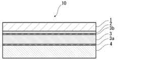
- the process film 10 of the present disclosure is, for example, from a laminate having a base material layer 1 and a heat-sealing resin layer 4 in this order, at least from the outside, as shown in FIGS. 4 to 8. It is configured.
- the base material layer 1 is on the outer layer side
- the heat-sealing resin layer 4 is on the inner layer side.
- the process film 10 may be a laminate of only the base material layer 1 and the heat-sealing resin layer 4. Further, as shown in FIGS. 5 to 8, a water vapor barrier layer 3 may be provided between the base material layer 1 and the heat-sealing resin layer 4. Further, it is preferable that the surface of the water vapor barrier layer 3 has a protective film, and FIGS. 5 to 8 show the water vapor barrier layer protective film 3b on the surface of the water vapor barrier layer 3 on the base material layer 1 side. The configuration in which the water vapor barrier layer protective film 3a is provided on the surface of the heat-sealing resin layer 4 side is shown. As shown in FIG.
- an adhesive layer 2 may be provided between the base material layer 1 and the water vapor barrier layer 3 for the purpose of enhancing the adhesiveness between these layers, if necessary. ..
- an adhesive layer 5 is provided between the water vapor barrier layer 3 and the heat-sealing resin layer 4 for the purpose of enhancing the adhesiveness between these layers, if necessary.
- the process film may include a buffer layer 6 if necessary, and as shown in FIG. 8, the buffer layer 6 is, for example, outside the base material layer 1 (with respect to the heat-sealing resin layer 4 side). It can be suitably provided on the opposite side) or the like.
- the buffer layer 6 may be adhered to the base material layer 1 to form a part of the process film 10, or may be used as a separate member from the process film 10 when the all-solid-state battery element is pressurized. It may be used together with the film 10.
- the thickness of the laminate constituting the process film 10 is not particularly limited, but is preferably about 10,000 ⁇ m or less, about 8,000 ⁇ m or less, about 5,000 ⁇ m or less, and about 100 ⁇ m or less, and protects the all-solid-state battery element during pressurization. From the viewpoint of suitably exhibiting the function of the process film 10, preferably about 5 ⁇ m or more, about 25 ⁇ m or more, about 100 ⁇ m or more, about 150 ⁇ m or more, about 200 ⁇ m or more, and the preferable range is, for example, 5 to 5 to.
- the step of pressurizing the all-solid-state battery element is generally performed in a dry room, but may also be performed in the atmosphere.
- the amount of water vapor permeation of the process film 10 is preferably small.
- the water vapor permeation amount of the process film 10 when left in an environment of 40 ° C. and 100% RH for 48 hours is preferably 10 cc / m 2 / day or less, more preferably 5 cc / m 2 / day.
- the method for measuring the water vapor permeation amount of the process film 10 is as follows.
- the process film 10 of the present disclosure is composed of a laminate having a base material layer 1 and a heat-sealing resin layer 4 in this order, at least from the outside.
- a layer constituting the process film 10 of the present disclosure will be described in detail.
- the base material layer 1 is a layer provided for the purpose of exerting a function as a protective member or a base material of the process film 10.
- the base material layer 1 is located on the outer layer side of the process film 10.
- the material forming the base material layer 1 is not particularly limited as long as it has a function as a protective member or a base material.
- the base material layer 1 can be formed by using, for example, a resin, and the resin may contain an additive described later. As will be described later, the base material layer 1 may form the cushioning layer 6. In this case, the material constituting the cushioning layer 6 described later is used as the material constituting the base material layer 1.
- a resin film formed of a resin may be used, or when the base material layer 1 is formed, a resin may be applied to form a resin film.
- the resin film may be an unstretched film or a stretched film.
- the stretched film include a uniaxially stretched film and a biaxially stretched film, and a biaxially stretched film is preferable.
- the stretching method for forming the biaxially stretched film include a sequential biaxial stretching method, an inflation method, and a simultaneous biaxial stretching method.
- the method of applying the resin include a roll coating method, a gravure coating method, and an extrusion coating method.
- the resin forming the base material layer 1 examples include resins such as polyester, polyamide, polyolefin, epoxy resin, acrylic resin, fluororesin, polyurethane, silicon resin, and phenol resin, and modified products of these resins. Further, the resin forming the base material layer 1 may be a copolymer of these resins or a modified product of the copolymer. Further, it may be a mixture of these resins.
- the resin forming the base material layer 1 is preferably polyester or polyamide.
- polyester examples include polyethylene terephthalate, polybutylene terephthalate, polyethylene naphthalate, polybutylene naphthalate, polyethylene isophthalate, and copolymerized polyester.
- polyethylene terephthalate is preferable.
- copolymerized polyester examples include a copolymerized polyester containing ethylene terephthalate as a repeating unit as a main component.
- a copolymer polyester (hereinafter abbreviated after polyethylene (terephthalate / isophthalate)), polyethylene (terephthalate / adipate), polyethylene (terephthalate / terephthalate /), which polymerizes with ethylene isophthalate using ethylene terephthalate as a repeating unit.
- polyethylene terephthalate / isophthalate
- adipate polyethylene
- terephthalate / terephthalate / polyethylene (terephthalate / adipate), polyethylene (terephthalate / terephthalate /), which polymerizes with ethylene isophthalate using ethylene terephthalate as a repeating unit.
- sodium sulfoisophthalate polyethylene (terephthalate / sodium isophthalate), polyethylene (terephthalate / phenyl-dicarboxylate), polyethylene (terephthalate / decandicarboxylate) and the like can
- polyamide examples include an aliphatic polyamide such as nylon 6, nylon 66, nylon 610, nylon 12, nylon 46, and a copolymer of nylon 6 and nylon 66; terephthalic acid and / or isophthalic acid.
- Hexamethylenediamine-isophthalic acid-terephthalic acid copolymerized polyamide such as nylon 6I, nylon 6T, nylon 6IT, nylon 6I6T (I stands for isophthalic acid, T stands for terephthalic acid), polyamide MXD6 (polymethaki Aroma-containing polyamides such as silylene adipamide); alicyclic polyamides such as polyamide PACM6 (polybis (4-aminocyclohexyl) methaneadipamide); further lactam components and isocyanate components such as 4,4'-diphenylmethane-diisocyanate.
- Examples thereof include a copolymerized polyamide, a polyesteramide copolymer and a polyether esteramide copolymer which are copolymers of a copolymerized polyamide and polyester or polyalkylene ether glycol; and polyamides such as these copolymers. These polyamides may be used alone or in combination of two or more.
- the base material layer 1 preferably contains at least one of a polyester film, a polyamide film, and a polyolefin film, and preferably contains at least one of a stretched polyester film, a stretched polyamide film, and a stretched polyolefin film. It is more preferable to contain at least one of a stretched polyethylene terephthalate film, a stretched polybutylene terephthalate film, a stretched nylon film, and a stretched polypropylene film, preferably a biaxially stretched polyethylene terephthalate film, a biaxially stretched polybutylene terephthalate film, and a biaxially stretched nylon film. , It is more preferable to contain at least one of the biaxially stretched polypropylene films.
- the base material layer 1 contains nylon from the viewpoint of increasing the durability of the process film 10 against pressure.
- the base material layer 1 preferably contains biaxially stretched polyethylene terephthalate.
- the base material layer 1 may be a single layer or may be composed of two or more layers.
- the base material layer 1 may be a laminated body in which a resin film is laminated with an adhesive or the like, or the resin is co-extruded to form two or more layers. It may be a laminated body of the resin film. Further, the laminated body of the resin film obtained by co-extruding the resin into two or more layers may be used as the base material layer 1 without being stretched, or may be uniaxially stretched or biaxially stretched as the base material layer 1.
- the base material layer 1 is a single layer, it is preferable that the base material layer 1 is composed of a single layer of polyester (particularly polyethylene terephthalate).
- the laminated body of two or more layers of resin film in the base material layer 1 a laminated body of a polyester film and a nylon film, a laminated body of two or more layers of nylon film, and a laminated body of two or more layers of polyester film.
- a laminated body of a stretched nylon film and a stretched polyester film preferably a laminated body of two or more layers of stretched nylon film, and a laminated body of two or more layers of stretched polyester film.
- the base material layer 1 is a laminate of two layers of resin film, the laminate of polyester film and polyester film, the laminate of polyamide resin film and polyamide resin film, or the laminate of polyester film and polyamide resin film is A laminate of a polyethylene terephthalate film and a polyethylene terephthalate film, a laminate of a nylon film and a nylon film, or a laminate of a polyethylene terephthalate film and a nylon film is more preferable.
- the base material layer 1 is a laminated body of two or more layers of resin films
- the two or more layers of resin films may be laminated via an adhesive.
- the preferable adhesive the same adhesives as those exemplified in the adhesive layer 2 described later can be mentioned.
- the method for laminating two or more layers of resin films is not particularly limited, and known methods can be adopted. Examples thereof include a dry laminating method, a sandwich laminating method, an extrusion laminating method, a thermal laminating method, and the like, and a dry laminating method is preferable.
- the laminating method can be mentioned.
- When laminating by the dry laminating method it is preferable to use a polyurethane adhesive as the adhesive.
- the thickness of the adhesive may be, for example, about 2 to 5 ⁇ m.
- an anchor coat layer may be formed on the resin film and laminated. Examples of the anchor coat layer include the same adhesives as those exemplified in the adhesive layer 2 described later. At this time, the thickness of the anchor coat layer may be, for example, about 0.01 to 1.0 ⁇ m.
- the melting point of the base material layer 1 is preferably 200 ° C. or higher, more preferably 200 to 450 ° C., and further preferably 200 to 350 ° C. Degree.
- the melting point is the melting peak temperature measured using a differential scanning calorimeter (DSC).
- additives such as a lubricant, a flame retardant, an antiblocking agent, an antioxidant, a light stabilizer, a tackifier, and an antistatic agent are present on at least one of the surface and the inside of the base material layer 1. good. Only one type of additive may be used, or two or more types may be mixed and used.
- the process film 10 may be molded and used.
- the process film 10 can be molded by a known method such as molding using a mold (cold molding or the like) or vacuum forming.
- a lubricant is present on the surface of the base material layer 1.
- the lubricant is not particularly limited, but an amide-based lubricant is preferable.
- the thickness of the base material layer 1 is not particularly limited as long as it functions as a protective member or a base material, and examples thereof include about 3 to 200 ⁇ m, preferably about 5 to 100 ⁇ m, and more preferably about 10 to 50 ⁇ m.
- the thickness of the resin films constituting each layer is preferably about 2 to 50 ⁇ m, respectively.
- a gas barrier film may be provided on one side or both sides of the base material layer 1.
- the gas barrier film is a film having a gas barrier property.
- the gas barrier film mainly contributes to the gas barrier property of the process film 10.
- the gas barrier film may be an inorganic substance or an organic substance, and preferably contains an inorganic substance because of its high gas barrier property.
- the gas barrier membrane may contain an organic and inorganic composite material.
- organic substance examples include ethylene-vinyl alcohol copolymer (EVOH), propylene-vinyl alcohol copolymer (PVOH), polyvinylidene chloride (PVDC) and the like.
- EVOH ethylene-vinyl alcohol copolymer
- PVH propylene-vinyl alcohol copolymer
- PVDC polyvinylidene chloride
- inorganic substances include metals (including alloys) and inorganic compounds.
- gas barrier film containing an inorganic substance include a metal film (for example, a metal vapor deposition film), a film containing an inorganic compound as a main component (hereinafter, may be referred to as an inorganic compound film), and an organic-inorganic composite described later. Materials and the like can be mentioned.
- the metal constituting the metal film examples include metals such as aluminum, stainless steel, titanium, nickel, iron, and copper, or alloys containing these. From the viewpoint of flexibility, it is particularly preferable that the metal film is aluminum.
- Inorganic compound As the inorganic compound constituting the film, for example, a compound containing a metal element such as silicon, aluminum, magnesium, calcium, potassium, tin, sodium, titanium, boron, yttrium, zirconium, cerium, zinc and the like or a non-metal element. Can be mentioned.
- examples of the above-mentioned inorganic compound include inorganic oxides, inorganic oxidative nitrides, inorganic nitrides, inorganic oxidative carbides, inorganic oxidative carbides, and zinc oxide.
- silicon oxides such as SiO 2
- aluminum oxides such as Al 2 O 3
- magnesium oxides titanium oxides, tin oxides, silicon zinc alloy oxides, indium alloy oxides, silicon nitrides, etc.
- examples thereof include aluminum nitride, titanium nitride, silicon oxide nitride and the like.
- the inorganic compound may be used alone or may be used by mixing the above-mentioned materials at an arbitrary ratio.
- the organic-inorganic composite material examples include a composite material of silica as an inorganic component and a resin as an organic component.
- a composite material of an inorganic component and an organic component for example, a material formed by adopting a sol-gel method is known, and as a specific example, a composite material of silica and polyvinyl alcohol (silica in polyvinyl alcohol (PVA)) is known. Is uniformly dispersed).
- the organic component in addition to PVA, PVA modified with a carboxyl group, an acetoacetyl group or the like can be used as the organic component, and silicon alkoxide (tetraethoxysilane, methyltriethoxysilane, etc.) is used as the inorganic component. be able to.
- the inorganic material is uniformly dispersed in the organic material to form a thin film layer.
- the organic and inorganic composite materials constituting the thin film layer may be of only one type or may be two or more types.
- the gas barrier film may be a coating film or a vapor-deposited film. Above all, a thin-film deposition film is preferable from the viewpoint of high adhesion to the base material layer 1 and high gas barrier performance.
- the gas barrier film may be a single film formed by single vapor deposition or a multilayer film formed by multiple vapor deposition. When the gas barrier film is a multilayer film, films having the same composition may be combined, or films having different compositions may be combined. When the gas barrier film is a multilayer film, the entire multilayer film is equivalent to one gas barrier film.
- the thickness of the gas barrier film is not particularly limited as long as it can exhibit the desired gas barrier property, and can be appropriately set according to the type of the gas barrier film.
- the thickness of the gas barrier film can be, for example, in the range of 5 nm or more and 200 nm or less, and more preferably in the range of 10 nm or more and 100 nm or less.
- the above thickness means the thickness per one time. If the thickness of the gas barrier film is less than the above range, the film formation may be insufficient and the desired gas barrier property may not be exhibited. In addition, strength may not be ensured and deterioration may occur over time. On the other hand, if the thickness of the gas barrier film exceeds the above range, defects may easily occur when a mechanical stress such as bending is applied, or the flexibility may decrease.
- the method for forming the gas barrier film may be any method as long as it can form a film with a desired thickness on one side or both sides of the base material layer 1, and is conventionally known depending on the type of the gas barrier film such as a coating method, a thin film deposition method, and a pressure bonding method. The method can be used.
- the adhesive layer 2 has adhesiveness between the base material layer 1 and the water vapor barrier layer 3 (in the case of having the water vapor barrier layer protective film 3b, the base material layer 1 and the water vapor barrier layer protective film 3b are attached to each other. It is a layer provided between these, if necessary, for the purpose of enhancing (adhesiveness).
- the adhesive layer 2 is formed by an adhesive capable of adhering the base material layer 1 and the water vapor barrier layer 3 (or the water vapor barrier layer protective film 3b).
- the adhesive used for forming the adhesive layer 2 is not limited, but may be any of a chemical reaction type, a solvent volatile type, a heat melting type, a thermal pressure type and the like. Further, it may be a two-component curable adhesive (two-component adhesive), a one-component curable adhesive (one-component adhesive), or a resin that does not involve a curing reaction. Further, the adhesive layer 2 may be a single layer or a multilayer.
- the adhesive component contained in the adhesive include polyesters such as polyethylene terephthalate, polybutylene terephthalate, polyethylene naphthalate, polybutylene naphthalate, polyethylene isophthalate, and copolymerized polyester; polyether; polyurethane; epoxy resin; Phenolic resin; Polyesters such as nylon 6, nylon 66, nylon 12, and copolymerized polyamides; Polyester resins such as polyolefins, cyclic polyolefins, acid-modified polyolefins, and acid-modified cyclic polyolefins; Polyvinyl acetate; Cellulose; (Meta) acrylic resins; Polyethylene; polycarbonate; amino resin such as urea resin and melamine resin; rubber such as chloroprene rubber, nitrile rubber and styrene-butadiene rubber; silicone resin and the like can be mentioned.
- polyesters such as polyethylene terephthalate, polybutylene terephthalate, poly
- adhesive components may be used alone or in combination of two or more.
- a polyurethane adhesive is preferable.
- the resin as an adhesive component can be used in combination with an appropriate curing agent to increase the adhesive strength.
- an appropriate one is selected from polyisocyanate, polyfunctional epoxy resin, oxazoline group-containing polymer, polyamine resin, acid anhydride and the like, depending on the functional group of the adhesive component.
- polyurethane adhesive examples include a polyurethane adhesive containing a first agent containing a polyol compound and a second agent containing an isocyanate compound.
- a polyol such as a polyester polyol, a polyether polyol, and an acrylic polyol is used as a first agent, and an aromatic or aliphatic polyisocyanate is used as a second agent.
- the polyol compound it is preferable to use a polyester polyol having a hydroxyl group in the side chain in addition to the hydroxyl group at the terminal of the repeating unit.
- the adhesive layer 2 may contain a colorant, a thermoplastic elastomer, a tackifier, a filler and the like, as long as the adhesiveness is not impaired, the addition of other components is permitted. Since the adhesive layer 2 contains a colorant, the process film 10 can be colored. As the colorant, known ones such as pigments and dyes can be used. Further, as the colorant, only one kind may be used, or two or more kinds may be mixed and used.
- the type of pigment is not particularly limited as long as it does not impair the adhesiveness of the adhesive layer 2.
- organic pigments include azo-based, phthalocyanine-based, quinacridone-based, anthracinone-based, dioxazine-based, indigothioindigo-based, perinone-perylene-based, isowearnine-based, and benzimidazolone-based pigments, which are inorganic.
- the pigment include carbon black-based, titanium oxide-based, cadmium-based, lead-based, chromium oxide-based, and iron-based pigments, and other examples include fine powder of mica (mica) and fish scale foil.
- carbon black is preferable in order to make the appearance of the process film 10 black.
- the average particle size of the pigment is not particularly limited, and examples thereof include about 0.05 to 5 ⁇ m, preferably about 0.08 to 2 ⁇ m.
- the average particle size of the pigment is the median diameter measured by the laser diffraction / scattering type particle size distribution measuring device.
- the content of the pigment in the adhesive layer 2 is not particularly limited as long as the process film 10 is colored, and examples thereof include about 5 to 60% by mass, preferably 10 to 40% by mass.
- the thickness of the adhesive layer 2 is not particularly limited as long as the base material layer 1 and the water vapor barrier layer 3 can be adhered to each other. Preferred ranges include about 1 to 10 ⁇ m, about 1 to 5 ⁇ m, about 2 to 10 ⁇ m, and about 2 to 5 ⁇ m.
- the colored layer is a layer provided between the base material layer 1 and the water vapor barrier layer 3 (or the water vapor barrier layer protective film 3b) or outside the base material layer 1 as needed (not shown).
- a colored layer is provided between the base material layer 1 and the adhesive layer 2 and between the adhesive layer 2 and the water vapor barrier layer 3 (or the water vapor barrier layer protective film 3b). May be good.
- a colored layer may be provided on the outside of the base material layer 1.
- the process film 10 can be colored. By coloring the process film 10, there is an advantage that it becomes easy to visually confirm that the pressurization of the all-solid-state battery element is uniformly performed.
- an ink containing a colorant is applied to the surface of the base material layer 1 or the surface of the water vapor barrier layer 3 (in the case of having the water vapor barrier layer protective film 3b, the surface of the water vapor barrier layer protective film 3b). It can be formed by doing.
- the colorant known ones such as pigments and dyes can be used. Further, as the colorant, only one kind may be used, or two or more kinds may be mixed and used. Further, when the coloring layer is provided on the outside of the base material layer 1, it may contain additives such as an antiblocking agent, a matting agent, a flame retardant, an antioxidant, a tackifier, and an antistatic agent.
- additives include talc, silica, graphite, kaolin, montmorillonite, mica, hydrotalcite, silica gel, zeolite, aluminum hydroxide, magnesium hydroxide, zinc oxide, magnesium oxide, aluminum oxide, neodium oxide, and antimony oxide.
- Titanium oxide, cerium oxide, calcium sulfate, barium sulfate, calcium carbonate, calcium silicate, lithium carbonate, calcium benzoate, calcium oxalate, magnesium stearate, alumina, carbon black, carbon nanotubes, melting point nylon, acrylate resin examples thereof include cross-linked acrylic, cross-linked styrene, cross-linked polyethylene, benzoguanamine, gold, aluminum, copper and nickel.
- the additive may be used alone or in combination of two or more.
- silica, barium sulfate, and titanium oxide are preferable from the viewpoint of dispersion stability and cost.
- the additive may be subjected to various surface treatments such as an insulation treatment and a high dispersibility treatment on the surface.
- colorant contained in the colored layer include the same as those exemplified in the column of [Adhesive layer 2].
- the water vapor barrier layer 3 is at least a layer that suppresses the infiltration of water, and is provided as needed.
- Examples of the water vapor barrier layer 3 include a metal foil having a barrier property, a thin-film deposition film, a resin layer, and the like.
- Examples of the vapor deposition film include a metal vapor deposition film, an inorganic oxide vapor deposition film, a carbon-containing inorganic oxide vapor deposition film, and the like, and examples of the resin layer include polymers and tetras mainly composed of polyvinylidene chloride and chlorotrifluoroethylene (CTFE).
- CTFE chlorotrifluoroethylene
- examples thereof include polymers having a main component of fluoroethylene (TFE), polymers having a fluoroalkyl group, fluorine-containing resins such as polymers having a fluoroalkyl unit as a main component, and ethylene vinyl alcohol copolymers.
- examples of the water vapor barrier layer 3 include a resin film provided with at least one of these vapor-deposited films and a resin layer. A plurality of layers of the water vapor barrier layer 3 may be provided.
- the water vapor barrier layer 3 preferably includes a layer made of a metal material. Specific examples of the metal material constituting the water vapor barrier layer 3 include an aluminum alloy, stainless steel, titanium steel, and a steel plate. When used as a metal foil, at least one of the aluminum alloy foil and the stainless steel foil is used. It is preferable to include it.
- the aluminum alloy foil is more preferably a soft aluminum alloy foil made of, for example, an annealed aluminum alloy from the viewpoint of improving the moldability of the process film 10, and from the viewpoint of further improving the moldability. It is preferably an aluminum alloy foil containing iron.
- the iron content is preferably 0.1 to 9.0% by mass, more preferably 0.5 to 2.0% by mass. When the iron content is 0.1% by mass or more, a process film having more excellent moldability can be obtained. When the iron content is 9.0% by mass or less, a process film having more flexibility can be obtained.
- the soft aluminum alloy foil for example, an aluminum alloy having a composition specified by JIS H4160: 1994 A8021HO, JIS H4160: 1994 A8079HO, JIS H4000: 2014 A8021P-O, or JIS H4000: 2014 A8079P-O. Foil is mentioned. Further, if necessary, silicon, magnesium, copper, manganese and the like may be added. Further, softening can be performed by annealing or the like.
- the stainless steel foil examples include austenite-based, ferrite-based, austenite-ferritic-based, martensitic-based, and precipitation-hardened stainless steel foil. Further, from the viewpoint of providing the process film 10 having excellent formability, the stainless steel foil is preferably made of austenitic stainless steel.
- austenitic stainless steel constituting the stainless steel foil include SUS304, SUS301, and SUS316L, and among these, SUS304 is particularly preferable.
- the thickness of the water vapor barrier layer 3 may be at least as long as it functions as a water vapor barrier layer that suppresses the infiltration of water, and is, for example, about 1 to 200 ⁇ m.
- the thickness of the water vapor barrier layer 3 is, for example, preferably about 85 ⁇ m or less, more preferably about 75 ⁇ m or less, still more preferably 70 ⁇ m or less, still more preferably about 50 ⁇ m or less, still more preferably about 40 ⁇ m or less, and more preferably.
- the thickness is preferably about 1 ⁇ m or more, more preferably about 5 ⁇ m or more, further preferably 45 ⁇ m or more, further preferably 50 ⁇ m or more, still more preferably 55 ⁇ m or more, and the preferred range of the thickness is about 1 to 85 ⁇ m, about 1 to 75 ⁇ m, and more.
- the process film 10 is peeled off from the all-solid-state battery element.
- the thickness of the water vapor barrier layer 3 is particularly preferably about 20 ⁇ m or less, about 10 ⁇ m or less, about 5 to 20 ⁇ m, and about 5 to 10 ⁇ m.
- a steam barrier layer protective film 3a is provided on the surface of the steam barrier layer 3 on the heat-sealing resin layer 4 side, if necessary.
- the water vapor barrier layer protective film 3a may be provided only on the surface of the water vapor barrier layer 3 on the heat-sealing resin layer 4 side, or the water vapor barriers may be provided on both sides of the water vapor barrier layer 3, respectively.
- the layer protective films 3a and 3b may be provided.
- the water vapor barrier layer protective films 3a and 3b can be formed by chemical conversion treatment of the surface of the water vapor barrier layer 3 with a treatment liquid containing a chromium compound such as chromium oxide.
- a chemical conversion treatment using a treatment liquid containing a chromium compound for example, a solution in which a chromium compound such as chromium oxide is dispersed in phosphoric acid and / or a salt thereof is applied to the surface of the water vapor barrier layer 3 and baked.
- a method of forming a water vapor barrier layer protective film on the surface of the water vapor barrier layer 3 can be mentioned.
- the thicknesses of the water vapor barrier layer protective films 3a and 3b are not particularly limited, respectively, but are preferably about 1 nm to 10 ⁇ m, more preferably about 1 to 100 nm, from the viewpoint of effectively suppressing deterioration of the water vapor barrier layer 3. , More preferably about 1 to 50 nm.
- the thickness of the water vapor barrier layer protective film can be measured by observation with a transmission electron microscope or a combination of observation with a transmission electron microscope and energy dispersion type X-ray spectroscopy or electron beam energy loss spectroscopy. ..
- the amount of the water vapor barrier layer protective films 3a and 3b per 1 m 2 of the surface of the water vapor barrier layer 3 is preferably about 1 to 500 mg, more preferably about 1 to 100 mg, and further preferably about 1 to 1, respectively. About 50 mg can be mentioned.
- Examples of the method of applying the treatment liquid containing the chromium compound to the surface of the water vapor barrier layer include a bar coating method, a roll coating method, a gravure coating method, and a dipping method.
- an alkaline dipping method, an electrolytic cleaning method and an acid cleaning method are used before providing the water vapor barrier layer protective films 3a and 3b on the surface of the water vapor barrier layer 3.
- a known treatment method such as an electrolytic acid cleaning method and an acid activation method.
- the heat-sealing resin layer 4 corresponds to the innermost layer, and the heat-sealing resin layers 4 are heat-sealed to each other to exhibit a function of covering the all-solid-state battery element ( Sealant layer).
- the heat-sealing method for heat-sealing the heat-sealing resin layers 4 include a bar seal, a hot plate seal, a rotary roll seal, a belt seal, an impulse seal, a high frequency seal, and an ultrasonic seal.
- the resin constituting the heat-fusing resin layer 4 is not particularly limited as long as it can be heat-fused, but a resin containing a polyolefin skeleton such as a polyolefin or an acid-modified polyolefin is preferable.
- a resin containing a polyolefin skeleton such as a polyolefin or an acid-modified polyolefin is preferable.
- the fact that the resin constituting the heat-sealing resin layer 4 contains a polyolefin skeleton can be analyzed by, for example, infrared spectroscopy, gas chromatography-mass spectrometry, or the like. Further, when the resin constituting the heat-sealing resin layer 4 is analyzed by infrared spectroscopy, it is preferable that a peak derived from maleic anhydride is detected.
- peaks derived from maleic anhydride are detected in the vicinity of wave number 1760 cm -1 and wave number 1780 cm -1 .
- the heat-sealing resin layer 4 is a layer composed of maleic anhydride-modified polyolefin, a peak derived from maleic anhydride is detected when measured by infrared spectroscopy.
- the degree of acid denaturation is low, the peak may become small and may not be detected. In that case, it can be analyzed by nuclear magnetic resonance spectroscopy.
- polystyrene resin examples include polyethylene such as low-density polyethylene, medium-density polyethylene, high-density polyethylene, and linear low-density polyethylene; ethylene- ⁇ -olefin copolymer; homopolypropylene, block copolymer of polypropylene (for example, with propylene).
- Polyethylene block copolymers random copolymers of polypropylene (eg, random copolymers of propylene and ethylene); propylene- ⁇ -olefin copolymers; ethylene-butene-propylene tarpolymers and the like.
- polypropylene is preferable.
- the polyolefin resin may be a block copolymer or a random copolymer. One of these polyolefin resins may be used alone, or two or more thereof may be used in combination.
- the polyolefin may be a cyclic polyolefin.
- the cyclic polyolefin is a copolymer of an olefin and a cyclic monomer, and examples of the olefin which is a constituent monomer of the cyclic polyolefin include ethylene, propylene, 4-methyl-1-pentene, styrene, butadiene, and isoprene. Be done.
- cyclic monomer which is a constituent monomer of the cyclic polyolefin examples include cyclic alkenes such as norbornene; cyclic diene such as cyclopentadiene, dicyclopentadiene, cyclohexadiene, and norbornadiene. Among these, cyclic alkene is preferable, and norbornene is more preferable.
- the acid-modified polyolefin is a polymer modified by block-polymerizing or graft-polymerizing the polyolefin with an acid component.
- the acid-modified polyolefin the above-mentioned polyolefin, a copolymer obtained by copolymerizing the above-mentioned polyolefin with a polar molecule such as acrylic acid or methacrylic acid, or a polymer such as a crosslinked polyolefin can also be used.
- the acid component used for acid modification include carboxylic acids such as maleic acid, acrylic acid, itaconic acid, crotonic acid, maleic anhydride, and itaconic anhydride, or anhydrides thereof.
- the acid-modified polyolefin may be an acid-modified cyclic polyolefin.
- the acid-modified cyclic polyolefin is a polymer obtained by copolymerizing a part of the monomers constituting the cyclic polyolefin in place of the acid component, or by block-polymerizing or graft-polymerizing the acid component with the cyclic polyolefin. be.
- the acid component used for acid denaturation is the same as the acid component used for denaturation of the polyolefin.
- Preferred acid-modified polyolefins include polyolefins modified with carboxylic acid or its anhydride, polypropylene modified with carboxylic acid or its anhydride, maleic anhydride-modified polyolefin, and maleic anhydride-modified polypropylene.
- the heat-sealing resin layer 4 may be formed of one type of resin alone, or may be formed of a blended polymer in which two or more types of resins are combined. Further, the heat-sealing resin layer 4 may be formed of only one layer, but may be formed of two or more layers with the same or different resins.
- the heat-sealing resin layer 4 is formed of a polybutylene terephthalate film or a polytetrafluoroethylene film. These films have excellent heat resistance and can be heat-sealed in a high temperature environment. Therefore, it is particularly effective when the process film 10 is used to pressurize the all-solid-state battery element in a high-temperature and high-pressure environment.
- the polybutylene terephthalate film or polytetrafluoroethylene film forming the heat-sealing resin layer 4 is heat-sealed by laminating a previously prepared polybutylene terephthalate film or polytetrafluoroethylene film with the adhesive layer 5, respectively.
- the sex resin layer 4 may be used, or the resin forming the polybutylene terephthalate film or the polytetrafluoroethylene film may be melt-extruded to form a film, or may be laminated with the adhesive layer 5.
- the polybutylene terephthalate film preferably further contains an elastomer in addition to polybutylene terephthalate.
- the elastomer plays a role of increasing the flexibility of the polybutylene terephthalate film while ensuring its durability in a high temperature environment.
- Preferred elastomers include polytetramethylene glycol.
- the content of the elastomer is not particularly limited as long as the durability of the polybutylene terephthalate film in a high temperature environment can be ensured and the flexibility thereof can be enhanced, for example, about 0.1 mass.
- the content is, for example, about 10.0% by mass or less, about 8.0% by mass or less, about 5.0% by mass or less, and the like.
- the preferable range of the content is about 0.1 to 10.0% by mass, about 0.1 to 8.0% by mass, about 0.1 to 5.0% by mass, and 0.5 to 10.0% by mass. %, 0.5 to 8.0% by mass, 0.5 to 5.0% by mass, 1.0 to 10.0% by mass, 1.0 to 8.0% by mass, 1.0 Examples thereof include about 5.0% by mass, about 3.0 to 10.0% by mass, about 3.0 to 8.0% by mass, and about 3.0 to 5.0% by mass.
- the heat-sealing resin layer 4 is formed of two or more layers, at least one layer is formed of a polybutylene terephthalate film or a polytetrafluoroethylene film, and the polybutylene terephthalate film is the innermost layer. It is preferable to have.
- the layer not formed of the polybutylene terephthalate film or the polytetrafluoroethylene film is, for example, a polyolefin such as polypropylene or polyethylene, or an acid-modified polypropylene. , It may be a layer formed of an acid-modified polyolefin such as acid-modified polyethylene.
- the heat-sealing resin layer 4 is made of polybutylene terephthalate film or polytetrafluoroethylene. It is preferably composed of only a film.
- a resin in which a vinyl polymer such as styrene is finely dispersed in polyrefin is used as the heat-sealed resin layer 4. It may be used for forming or imparting adhesiveness to the heat-sealing resin layer 4. By doing so, when the process film 10 is peeled from the all-solid-state battery element, it is not necessary to cut the process film 10 with scissors or a cutter, and the peeling step can be easily performed.
- the melting point of the heat-sealing resin layer 4 is preferably about 140 to 240 ° C., more preferably 140 to 230 ° C. from the viewpoint of enhancing the durability against pressurization in a high temperature and high pressure environment and the heat fusion property by heat sealing. Degree.
- the melting point is the melting peak temperature measured using a differential scanning calorimeter (DSC).
- the heat-sealing resin layer 4 may contain a moisture-adsorbing material, if necessary.
- the water adsorbing material is not particularly limited, and a known water adsorbing material can be used.
- the water adsorbing material may be used alone or in combination of two or more.
- the water adsorbing material is not particularly limited, but is preferably a group consisting of calcium oxide, anhydrous magnesium sulfate, magnesium oxide, calcium chloride, zeolite, synthetic zeolite, aluminum oxide, silica gel, alumina gel, silica alumina gel, and baked myoban. Examples thereof include materials containing one or more selected from the above. Of these, calcium oxide and anhydrous magnesium sulfate are particularly preferable.
- the content thereof may be, for example, 0.1 to 50% by mass.
- the heat-sealing resin layer 4 may contain a hydrogen sulfide absorbing material, if necessary.
- the hydrogen sulfide absorbing material is not particularly limited, and a known hydrogen sulfide absorbing material can be used.
- the hydrogen sulfide absorbing material may be used alone or in combination of two or more.
- the heat-sealing resin layer 4 may contain both a water-adsorbing material and a hydrogen sulfide absorbing material, if necessary.
- the hydrogen sulfide absorbing material is not particularly limited, but is a metal oxide and / or an inorganic substance carrying or mixed with a metal or a metal ion, and the metal oxide is preferably selected from the group consisting of CuO, ZnO, and AgO.
- the metal species of one or more kinds of materials, metals or inorganic substances carrying or mixed with metal ions consist of Ca, Mg, Na, Cu, Zn, Ag, Pt, Au, Fe, Al and Ni.
- the hydrogen sulfide absorbing material has a maximum particle diameter of 20 ⁇ m or less, and a number average particle diameter of 0.1 ⁇ m or more and 15 ⁇ m or less.
- the content thereof may be, for example, 0.3 to 30% by mass.
- the heat-sealing resin layer 4 contains a water-adsorbing material or a hydrogen sulfide absorbing material
- the heat-sealing resin layer 4 is composed of two or more layers, the innermost layer does not contain a water-adsorbing material or a hydrogen sulfide absorbing material, but is contained in the layer on the base material layer 1 side. Is preferable.
- the heat-sealing resin layer 4 may contain a lubricant or the like, if necessary.
- a lubricant When the heat-bondable resin layer 4 contains a lubricant, the moldability of the process film can be improved.
- the lubricant is not particularly limited, and a known lubricant can be used.
- the lubricant may be used alone or in combination of two or more.
- the lubricant is not particularly limited, but an amide-based lubricant is preferable. Specific examples of the lubricant include those exemplified in the base material layer 1. The lubricant may be used alone or in combination of two or more.
- the amount thereof is not particularly limited, but is preferably about 10 to 50 mg / m 2 from the viewpoint of improving the formability of the process film, more preferably about 10 to 50 mg / m 2 . Is about 15 to 40 mg / m 2 .
- the lubricant present on the surface of the heat-sealing resin layer 4 may be one in which the lubricant contained in the resin constituting the heat-sealing resin layer 4 is exuded, or the lubricant of the heat-sealing resin layer 4 may be exuded.
- the surface may be coated with a lubricant.
- the thickness of the heat-sealing resin layer 4 is not particularly limited as long as the heat-sealing resin layers have a function of heat-sealing to cover the all-solid-state battery element, but is preferably about 100 ⁇ m or less, for example. Is about 85 ⁇ m or less, more preferably about 15 to 85 ⁇ m. For example, when the thickness of the adhesive layer 5 described later is 10 ⁇ m or more, the thickness of the heat-sealing resin layer 4 is preferably about 85 ⁇ m or less, more preferably about 15 to 45 ⁇ m, for example.
- the thickness of the heat-sealing resin layer 4 is preferably about 20 ⁇ m or more, more preferably 35 to 85 ⁇ m. The degree can be mentioned.
- the adhesive layer 5 firmly adheres the water vapor barrier layer 3 (the water vapor barrier layer protective film 3a when the water vapor barrier layer protective film 3a is provided) and the heat-sealing resin layer 4 to each other. It is a layer provided between.
- the adhesive layer 5 is formed of a resin capable of adhering the water vapor barrier layer 3 and the heat-sealing resin layer 4.
- the resin used for forming the adhesive layer 5 for example, the same adhesive as that exemplified in the adhesive layer 2 can be used.
- the adhesive layer 5 is preferably a cured product of a resin composition containing a curing agent.
- the curing agent examples include a curing agent having an oxazoline group and a curing agent having an isocyanate group.
- the curing agent having a C—O—C bond examples include a curing agent having an oxazoline group and a curing agent having an epoxy group.
- the fact that the adhesive layer 5 is a cured product of a resin composition containing these curing agents is, for example, gas chromatograph mass spectrometry (GCMS), infrared spectroscopy (IR), time-of-flight secondary ion mass spectrometry (TOF). -SIMS), X-ray photoelectron spectroscopy (XPS) and other methods can be used for confirmation.
- GCMS gas chromatograph mass spectrometry
- IR infrared spectroscopy
- TOF time-of-flight secondary ion mass spectrometry
- -SIMS X-ray photoelectron spectroscopy
- XPS X-ray photoele
- the compound having an isocyanate group is not particularly limited, but a polyfunctional isocyanate compound is preferable from the viewpoint of effectively enhancing the adhesion between the water vapor barrier layer 3 and the adhesive layer 5.
- the polyfunctional isocyanate compound is not particularly limited as long as it is a compound having two or more isocyanate groups.
- Specific examples of the polyfunctional isocyanate-based curing agent include pentandiisocyanate (PDI), isophorone diisocyanate (IPDI), hexamethylene diisocyanate (HDI), tolylene diisocyanate (TDI), and diphenylmethane diisocyanate (MDI), which are polymerized or nurate. Examples thereof include chemical compounds, mixtures thereof, and copolymers with other polymers.
- an adduct body, a biuret body, an isocyanate body and the like can be mentioned.
- the content of the compound having an isocyanate group in the adhesive layer 5 is preferably in the range of 0.1 to 50% by mass, and 0.5 to 40% by mass in the resin composition constituting the adhesive layer 5. It is more preferable to be in the range. This makes it possible to effectively improve the adhesion between the water vapor barrier layer 3 and the adhesive layer 5.
- the compound having an oxazoline group is not particularly limited as long as it is a compound having an oxazoline skeleton.
- Specific examples of the compound having an oxazoline group include those having a polystyrene backbone and those having an acrylic backbone. Examples of commercially available products include the Epocross series manufactured by Nippon Shokubai Co., Ltd.
- the proportion of the compound having an oxazoline group in the adhesive layer 5 is preferably in the range of 0.1 to 50% by mass, preferably in the range of 0.5 to 40% by mass in the resin composition constituting the adhesive layer 5. It is more preferable to be in. This makes it possible to effectively improve the adhesion between the water vapor barrier layer 3 and the adhesive layer 5.
- Examples of the compound having an epoxy group include an epoxy resin.
- the epoxy resin is not particularly limited as long as it is a resin capable of forming a crosslinked structure by an epoxy group existing in the molecule, and a known epoxy resin can be used.
- the weight average molecular weight of the epoxy resin is preferably about 50 to 2000, more preferably about 100 to 1000, and even more preferably about 200 to 800.
- the weight average molecular weight of the epoxy resin is a value measured by gel permeation chromatography (GPC) measured under the condition of using polystyrene as a standard sample.
- epoxy resin examples include glycidyl ether derivative of trimethylolpropane, bisphenol A diglycidyl ether, modified bisphenol A diglycidyl ether, bisphenol F type glycidyl ether, novolak glycidyl ether, glycerin polyglycidyl ether, polyglycerin polyglycidyl ether and the like. Can be mentioned.
- One type of epoxy resin may be used alone, or two or more types may be used in combination.
- the proportion of the epoxy resin in the adhesive layer 5 is preferably in the range of 0.1 to 50% by mass, preferably in the range of 0.5 to 40% by mass in the resin composition constituting the adhesive layer 5. Is more preferable. This makes it possible to effectively improve the adhesion between the water vapor barrier layer 3 and the adhesive layer 5.
- the polyurethane is not particularly limited, and known polyurethane can be used.
- the adhesive layer 5 may be, for example, a cured product of a two-component curable polyurethane.
- the proportion of polyurethane in the adhesive layer 5 is preferably in the range of 0.1 to 50% by mass, and preferably in the range of 0.5 to 40% by mass in the resin composition constituting the adhesive layer 5. More preferred. This makes it possible to effectively enhance the adhesion between the water vapor barrier layer 3 and the adhesive layer 5 in an atmosphere in which a component that induces corrosion of the water vapor barrier layer such as an electrolytic solution is present.
- the adhesive layer 5 is formed by a cured product of a resin composition containing at least one of polyester and polycarbonate and at least one of an alicyclic isocyanate compound and an aromatic isocyanate compound. It is also preferable to be.
- the polyester is preferably a polyester polyol.
- the polyester polyol is not particularly limited as long as it has an ester bond in the polymer backbone and has a plurality of hydroxyl groups at the terminal or side chain.
- the polycarbonate is preferably a polycarbonate polyol.
- the polyester polyol is not particularly limited as long as it has a carbonate bond in the polymer backbone and has a plurality of hydroxyl groups at the terminal or side chain.
- the polyester and polycarbonate contained in the resin composition forming the adhesive layer 5 may be of one type or two or more types, respectively.
- the alicyclic isocyanate compound is not particularly limited as long as it is a compound having an alicyclic structure and an isocyanate group.
- the alicyclic isocyanate compound preferably has two or more isocyanate groups.
- Specific examples of the alicyclic isocyanate compound include isophorone diisocyanate (IPDI), which is polymerized or nurate, a mixture thereof, or a copolymer with another polymer. Further, an adduct body, a burette body, an isocyanate body and the like can be mentioned.
- IPDI isophorone diisocyanate
- the alicyclic isocyanate compound contained in the resin composition forming the adhesive layer 5 may be one kind or two or more kinds.
- the aromatic isocyanate compound is not particularly limited as long as it is a compound having an aromatic ring and an isocyanate group.
- the aromatic isocyanate compound preferably has two or more isocyanate groups.
- Specific examples of the aromatic isocyanate compound include tolylene diisocyanate (TDI), diphenylmethane diisocyanate (MDI), those obtained by polymerizing or nucleating them, mixtures thereof, and copolymers with other polymers. Further, an adduct body, a burette body, an isocyanate body and the like can be mentioned.
- the aromatic isocyanate compound contained in the resin composition forming the adhesive layer 5 may be one kind or two or more kinds.
- the resin composition forming the adhesive layer 5 contains at least one of the alicyclic isocyanate compound and the aromatic isocyanate compound
- the alicyclic isocyanate compound may be contained and the aromatic isocyanate compound may not be contained.
- the aromatic isocyanate compound may be contained and the alicyclic isocyanate compound may not be contained, or for example, both the alicyclic isocyanate compound and the aromatic isocyanate compound may be contained.
- the content of the alicyclic isocyanate compound and the aromatic isocyanate compound in the adhesive layer 5 is preferably in the range of 0.1 to 50% by mass, respectively, in the resin composition constituting the adhesive layer 5, and is 0. More preferably, it is in the range of .5 to 40% by mass.
- the adhesive layer 5 contains both an alicyclic isocyanate compound and an aromatic isocyanate compound, the total content of these is in the range of 0.1 to 50% by mass in the resin composition constituting the adhesive layer 5. It is preferably in the range of 0.5 to 40% by mass, and more preferably in the range of 0.5 to 40% by mass.
- the thickness of the adhesive layer 5 is preferably about 50 ⁇ m or less, about 40 ⁇ m or less, about 30 ⁇ m or less, about 20 ⁇ m or less, about 5 ⁇ m or less, and preferably about 0.1 ⁇ m or more and about 0.5 ⁇ m or more.
- the thickness range is preferably about 0.1 to 50 ⁇ m, about 0.1 to 40 ⁇ m, about 0.1 to 30 ⁇ m, about 0.1 to 20 ⁇ m, about 0.1 to 5 ⁇ m, and the like. Examples thereof include about 0.5 to 50 ⁇ m, about 0.5 to 40 ⁇ m, about 0.5 to 30 ⁇ m, about 0.5 to 20 ⁇ m, and about 0.5 to 5 ⁇ m.
- the process film 10 may include a buffer layer 6 in order to provide a buffer function that uniformly disperses the pressure due to the pressurization of the all-solid-state battery element.
- the cushioning layer 6 may be located outside the heat-sealing resin layer 4 of the process film 10, and is preferably located outside the base material layer 1.
- the base material layer 1 may form the buffer layer 6.
- the material described later that constitutes the buffer layer 6 is used as the material of the base material layer 1. By doing so, the process film 10 can be provided with a buffering function without providing the buffering layer 6 separately from the base material layer 1.
- the material constituting the cushioning layer 6 is not particularly limited as long as it can function as a cushion for a high-pressure press (can disperse pressure), and preferably includes rubber, a non-woven fabric, and a foamed sheet.
- the rubber is not particularly limited as long as it has elasticity, and examples thereof include natural rubber, fluorine rubber, and silicon rubber.
- the rubber hardness is preferably about 20 to 90.
- the material constituting the non-woven fabric is not particularly limited, and preferably the same resin as the resin exemplified in the base material layer 1 described later is exemplified. Since the all-solid-state battery is expected to be used in a high temperature environment, it is preferable that the non-woven fabric is made of a material having excellent heat resistance.
- the buffer layer 6 is preferably about 20 g / m 2 or more, more preferably about 30 g / m 2 or more, and further preferably 100 g / m. 2 or more, preferably about 300 g / m 2 or less, more preferably about 200 g / m 2 or less, and preferable ranges are about 20 to 300 g / m 2 and about 20 to 200 g / m 2 .
- About / m 2 is particularly preferable.
- the fiber diameter of the fibers constituting the buffer layer 6 is preferably about 5 ⁇ m or more, more preferably about 15 ⁇ m or more, and further. It is preferably 60 ⁇ m or less, more preferably about 40 ⁇ m or less, and preferred ranges are about 5 to 60 ⁇ m, about 5 to 40 ⁇ m, about 15 to 60 ⁇ m, and about 15 to 40 ⁇ m, and particularly preferably about 5 to 40 ⁇ m. Is.
- the thickness of the buffer layer 6 is preferably about 100 ⁇ m or more, about 200 ⁇ m or more, about 1000 ⁇ m or more, and about 5000 ⁇ m or less, about 3000 ⁇ m or less, and the preferred range is about 100 to 5000 ⁇ m, about 100 to 3000 ⁇ m, 200 to. Examples thereof include about 5000 ⁇ m, about 200 to 3000 ⁇ m, about 1000 to 5000 ⁇ m, and about 1000 to 3000 ⁇ m, and among these, 1000 to 3000 ⁇ m is particularly preferable.
- the cushioning layer 6 may be adhered to the base material layer 1 to form a part of the process film 10, or may be used as a separate member from the process film 10 when the all-solid-state battery element is pressurized. It may be used together with the process film 10.
- the method for producing the process film 10 is not particularly limited as long as a laminate obtained by laminating the layers of the process film 10 can be obtained, and at least the base material layer 1 and the heat-sealing resin layer 4 are present from the outside.
- An example is a method including a step of laminating in order.
- the base material layer 1 and the heat-bondable resin layer 4 can be laminated by bonding using the adhesive layer 2, a thermal laminating method, melt extrusion, or the like.
- an example of the method for producing the process film 10 is as follows. First, a laminate in which the base material layer 1, the adhesive layer 2, and the water vapor barrier layer 3 are laminated in this order (hereinafter, may be referred to as “laminate A”) is formed. Specifically, the laminated body A is formed by applying the adhesive used for forming the adhesive layer 2 on the base material layer 1 or the water vapor barrier layer 3 by a gravure coating method, a roll coating method, or the like. After coating and drying, it can be carried out by a dry laminating method in which the water vapor barrier layer 3 or the base material layer 1 is laminated to cure the adhesive layer 2.
- the heat-sealing resin layer 4 is laminated on the water vapor barrier layer 3 of the laminated body A.
- the resin component constituting the heat-sealing resin layer 4 is gravure-coated and rolled on the water vapor barrier layer 3 of the laminated body A. It may be applied by a method such as a coating method.
- the adhesive layer 5 is provided between the water vapor barrier layer 3 and the heat-sealing resin layer 4, for example, (1) the adhesive layer 5 and the heat-sealing property are placed on the water vapor barrier layer 3 of the laminated body A.
- a method of laminating by co-extruding the resin layer 4 (co-extruded laminating method), (2) Separately, a laminated body in which the adhesive layer 5 and the heat-sealing resin layer 4 are laminated is formed, and this is combined with the laminated body A.
- a method of laminating on the water vapor barrier layer 3 by the thermal laminating method (3) an adhesive for forming the adhesive layer 5 is extruded or solution coated on the water vapor barrier layer 3 of the laminated body A, and further dried at a high temperature. Is laminated by a baking method or the like, and a heat-sealing resin layer 4 having a sheet-like film formed in advance on the adhesive layer 5 is laminated by a thermal laminating method.
- the buffer layer 6 is laminated on the outside of the base material layer 1.
- An adhesive or the like can be used for laminating the cushioning layer 6.
- the base material layer 1 may form the buffer layer 6.
- the material constituting the buffer layer 6 is used as the material constituting the base material layer 1.
- the buffer layer 6 provided as needed / the base material layer 1 may constitute the buffer layer 6) / the adhesive layer 2 provided as needed / provided as needed.
- the water vapor barrier layer protective film 3b / the water vapor barrier layer 3 provided as needed / the water vapor barrier layer protective film 3a provided as needed / the adhesive layer 5 provided as needed / the heat-sealing resin layer 4 are formed.
- Laminates are formed in order, but in order to strengthen the adhesiveness of the adhesive layer 2 and the adhesive layer 5 provided as needed, a hot roll contact type, a hot air type, a near infrared type or a far infrared ray is further formed. It may be subjected to heat treatment such as a formula. Examples of the conditions for such heat treatment include about 1 to 5 minutes at about 150 to 250 ° C.
- Each layer constituting the process film 10 is corona-treated or blasted in order to improve or stabilize film-forming property, laminating process, final product secondary process (pouching, embossing) suitability, etc., as necessary.
- Surface activation treatment such as treatment, oxidation treatment, and ozone treatment may be performed.
- a corona treatment to at least one surface of the base material layer 1, film forming property, laminating processing, suitability for secondary processing of final products, and the like can be improved or stabilized.
- the all-solid-state battery element to which the process film 10 of the present disclosure (hereinafter, may be referred to as “process film 10”) is applied is not particularly limited. That is, the battery element of the all-solid-state battery is not particularly limited, and may be one used in a known all-solid-state battery.
- FIGS. 1 to 3 are schematic views showing how the all-solid-state battery element is coated with the process film of the present disclosure.
- a single battery including a positive electrode active material layer 31, a negative electrode active material layer 21, and a solid electrolyte layer 40 laminated between the positive electrode active material layer 31 and the negative electrode active material layer 21.
- the all-solid battery element including at least 50, is coated with the process film 10 of the present disclosure. More specifically, the positive electrode active material layer 31 is laminated on the positive electrode current collector 32 to form the positive electrode layer 30, and the negative electrode active material layer 21 is laminated on the negative electrode current collector 22 to form the negative electrode. It constitutes layer 20.
- the positive electrode current collector 32 and the negative electrode current collector 22 are each joined to an externally exposed terminal 60 and electrically connected to the external environment.
- a solid electrolyte layer 40 is laminated between the positive electrode layer 30 and the negative electrode layer 20, and the positive electrode layer 30, the negative electrode layer 20, and the solid electrolyte layer 40 constitute the cell 50.
- the all-solid-state battery element may include only one cell cell 50, or may include a plurality of cell cells 50.
- FIG. 1 illustrates an all-solid-state battery element including two cell cells 50
- FIG. 2 illustrates an embodiment in which three cell cells 50 are laminated to form an all-solid-state battery element. There is.
- the all-solid-state battery element is covered with the process film 10, and at least a part of the heat-sealing resin layers 4 at the peripheral edge of the process film 10 is heat-sealed and subjected to pressurization in this state.
- the all-solid-state battery element may be covered with the process film 10 so that all the terminals 60 are inside the peripheral portion of the process film 10 (see FIG. 9), and the terminals 60 are placed on the outside of the peripheral portion.
- the all-solid-state battery element may be coated with the process film 10 in a protruding state (see FIGS. 10 and 11).
- the all-solid-state battery element is sealed (see FIGS. 9 and 10).
- the heat-sealing resin portion of the process film 10 of the present disclosure is arranged to be inside (the surface in contact with the battery element). To form a package.
- FIGS. 9 to 10 are schematic plan views showing a state in which the process film 10 is used without being molded and the process film 10 is covered with the all-solid-state battery element.
- the terminal 60 has adhesiveness. It is preferable to arrange the film 61.
- FIG. 9 shows how the terminals 60 of the all-solid-state battery element and the adhesive film 61 are all sealed in the package formed by the process film 10. In FIG. 9, the entire terminal 60 is sealed inside the heat-sealed portion S formed by the heat seal on the peripheral edge of the process film 10. Further, in FIGS.
- the process film 10 is heat-sealed from above the terminal 60 with the tip of the terminal 60 of the all-solid-state battery element protruding from the package.
- the adhesive film 61 exists inside the heat-sealed portion S at the peripheral edge of the process film 10, and the adhesive film 61 is not heat-sealed and the package is sealed.
- the adhesive film 61 may be present outside the heat-sealed portion S at the peripheral edge of the process film 10.
- the adhesive film 61 is located on the peripheral edge of the process film 10, but the heat-sealed portion S is provided on the peripheral edge of the process film 10 so as to avoid the adhesive film 61. Is shown.
- the package is not sealed.
- the terminals 60 of the all-solid-state battery element and the adhesive film 61 are all contained in the package formed of the process film 10. It is preferable to seal it. Further, as shown in FIG. 10, when the heat-sealed portion S is formed on the terminal 60, the adhesion between the terminal 60 and the packaging material for the all-solid-state battery is low, so that the peeling is triggered by the peeling after pressurization. Can be facilitated.
- the process film 10 is peeled off from the all-solid-state battery element, as shown in the schematic views of FIGS. The process film 10 may be cut along the line S.
- the all-solid-state battery element to which the process film 10 of the present disclosure is applied is not particularly limited.
- the materials and the like of the members constituting the all-solid-state battery element to which the process film 10 of the present disclosure is applied will be exemplified.
- the positive electrode layer 30 has a structure in which the positive electrode active material layer 31 is laminated on the positive electrode current collector 32.
- the negative electrode layer 20 has a structure in which the negative electrode active material layer 21 is laminated on the negative electrode current collector 22.
- the positive electrode current collector 32 and the negative electrode current collector 22 are each joined to an externally exposed terminal 60 and electrically connected to the external environment.
- the positive electrode active material layer 31 is a layer containing at least a positive electrode active material.
- the positive electrode active material layer 31 may further contain a solid electrolyte material, a conductive material, a binder, and the like, if necessary, in addition to the positive electrode active material.
- the positive electrode active material is not particularly limited, and examples thereof include an oxide active material and a sulfide active material.
- the oxide active material used as the positive electrode active material include LiCoO 2 , LiMnO 2 , LiNiO 2 , LiVO 2 , and LiNi 1/3 Co 1/3 Mn 1 . / 3 O 2 and other rock salt layered active materials, LiMn 2 O 4 , Li (Ni 0.5 Mn 1.5 ) O 4 and other spinel type active materials, LiFePO 4 , LiMnPO 4 and other olivine type active materials, Li 2 FeSiO 4 , Examples thereof include Si-containing active materials such as Li 2 MnSiO 4 .
- the sulfide active material used as the positive electrode active material of the all-solid-state lithium battery include copper sulphur, iron sulfide, cobalt sulfide, nickel sulfide and the like.
- the shape of the positive electrode active material is not particularly limited, and examples thereof include a particle shape.
- the average particle size (D 50 ) of the positive electrode active material is preferably, for example, about 0.1 to 50 ⁇ m.
- the content of the positive electrode active material in the positive electrode active material layer 31 is preferably about 10 to 99% by mass, more preferably about 20 to 90% by mass.
- the positive electrode active material layer 31 preferably further contains a solid electrolyte material. This makes it possible to improve the ionic conductivity in the positive electrode active material layer 31.
- the solid electrolyte material contained in the positive electrode active material layer 31 is the same as the solid electrolyte material exemplified in the solid electrolyte layer 40 described later.
- the content of the solid electrolyte material in the positive electrode active material layer is preferably about 1 to 90% by mass, more preferably about 10 to 80% by mass.
- the positive electrode active material layer 31 may further contain a conductive material. By adding the conductive material, the electron conductivity of the positive electrode active material layer can be improved. Examples of the conductive material include acetylene black, ketjen black, carbon fiber and the like. Further, the positive electrode active material layer may further contain a binder. Examples of the binder include fluorine-containing binders such as polytetrafluoroethylene (PTFE) and polyvinylidene fluoride (PVDF).
- PTFE polytetrafluoroethylene
- PVDF polyvinylidene fluoride
- the thickness of the positive electrode active material layer 31 is appropriately set according to the size of the all-solid-state battery and the like, but is preferably about 0.1 to 1000 ⁇ m.
- Patent current collector 32 examples of the material constituting the positive electrode current collector 32 include stainless steel (SUS), aluminum, nickel, iron, titanium, carbon and the like.
- the thickness of the positive electrode current collector 32 is appropriately set according to the size of the all-solid-state battery and the like, but is preferably about 10 to 1000 ⁇ m.
- the negative electrode active material layer 21 is a layer containing at least the negative electrode active material.
- the negative electrode active material layer 21 may contain, if necessary, a solid electrolyte material, a conductive material, a binder, and the like, in addition to the negative electrode active material.
- the negative electrode active material is not particularly limited, and examples thereof include a carbon active material, a metal active material, and an oxide active material.
- the carbon active material include graphite such as mesocarbon microbeads (MCMB) and highly oriented graphite (HOPG), and amorphous carbon such as hard carbon and soft carbon.
- the metal active material include In, Al, Si and Sn.
- the oxide active material include Nb 2 O 5 , Li 4 Ti 5 O 12 , SiO and the like.
- the shape of the negative electrode active material is not particularly limited, and examples thereof include a particle shape and a film shape.
- the average particle size (D 50 ) of the negative electrode active material is preferably about 0.1 to 50 ⁇ m.
- the content of the negative electrode active material in the negative electrode active material layer 21 is, for example, about 10 to 99% by mass, more preferably about 20 to 90% by mass.
- the negative electrode active material layer 21 preferably further contains a solid electrolyte material. This makes it possible to improve the ionic conductivity in the negative electrode active material layer 21.
- the solid electrolyte material contained in the negative electrode active material layer 21 is the same as the solid electrolyte material exemplified in the solid electrolyte layer 40 described later.
- the content of the solid electrolyte material in the negative electrode active material layer 21 is preferably about 1 to 90% by mass, more preferably about 10 to 80% by mass.
- the negative electrode active material layer 21 may further contain a conductive material. Further, the negative electrode active material layer 21 may further contain a binder.
- the conductive material and the binder are the same as those exemplified for the positive electrode active material layer 31 described above.
- the thickness of the negative electrode active material layer 21 is appropriately set according to the size of the all-solid-state battery and the like, but is preferably about 0.1 to 1000 ⁇ m.
- Negative electrode current collector 22 Examples of the material constituting the negative electrode current collector 22 include stainless steel (SUS), copper, nickel, carbon and the like.
- the thickness of the negative electrode current collector 22 is appropriately set according to the size of the all-solid-state battery and the like, but is preferably about 10 to 1000 ⁇ m.
- Solid electrolyte layer 40 is a layer containing a solid electrolyte material.
- the solid electrolyte material include a sulfide solid electrolyte material and an oxide solid electrolyte material.
- the sulfide solid electrolyte material is preferable in that many of them have higher ionic conductivity than the oxide solid electrolyte material, and the oxide solid electrolyte material has higher chemical stability than the sulfide solid electrolyte material. Preferred in terms of points.
- the oxide solid electrolyte material include compounds having a NASICON type structure and the like.
- a compound represented by the general formula Li 1 + x Al x Ge 2-x (PO 4 ) 3 (0 ⁇ x ⁇ 2) can be mentioned.
- the above compound is preferably Li 1.5 Al 0.5 Ge 1.5 (PO 4 ) 3 .
- a compound represented by the general formula Li 1 + x AlxTi 2-x (PO 4 ) 3 (0 ⁇ x ⁇ 2) can be mentioned.
- the above compound is preferably Li 1.5 Al 0.5 Ti 1.5 (PO 4 ) 3 .
- LiLaTIO for example, Li 0.34 La 0.51 TiO 3
- LiPON for example, Li 2.9 PO 3.3 N 0.46
- LiLaZrO for example, LiLaZrO
- Li 7 La 3 Zr 2 O 12 Li 7 La 3 Zr 2 O 12
- the sulfide solid electrolyte material include, for example, Li 2 SP 2 S 5 , Li 2 SP 2 S 5 -Li I, Li 2 SP 2 S 5 -Li 2 O, Li 2 S-. P 2 S 5 -Li 2 O-LiI, Li 2 S-SiS 2 , Li 2 S-SiS 2 -LiI, Li 2 S-SiS 2 -LiBr, Li 2 S-SiS 2 -LiCl, Li 2 S-SiS 2 -B 2 S 3 -Li I, Li 2 S-SiS 2 -P 2 S 5 -Li I, Li 2 SB 2 S 3 , Li 6 PS 5 Cl, Li 7 P 3 S 11 , Li 2 SP 2 S 5 -ZmSn (where m and n are positive numbers; Z is any of Ge, Zn, Ga), Li 2S-GeS 2 , Li 2S -SiS 2 - Li 3 PO 4 , Li 2 S -
- Li 2 SP 2 S 5" means a sulfide solid electrolyte material using a raw material composition containing Li 2 S and P 2 S 5 , and the same applies to other descriptions. be. Further, the sulfide solid electrolyte material may be sulfide glass or crystallized sulfide glass.
- the content of the solid electrolyte material in the solid electrolyte layer 40 is not particularly limited, but is preferably 60% by mass or more, more preferably 70% by mass or more, and further preferably 80% by mass or more.
- the solid electrolyte layer may contain a binder or may be composed of only the solid electrolyte material.
- the thickness of the solid electrolyte layer 40 is appropriately set according to the size of the all-solid-state battery and the like, but is preferably about 0.1 to 1000 ⁇ m, more preferably about 0.1 to 300 ⁇ m.
- the pressure applied to the all-solid-state battery element is from the viewpoint of preferably suppressing the peeling between the solid electrolyte and the negative electrode active material layer (further, between the solid electrolyte and the positive electrode active material layer). It is preferably about 1 MPa or more, more preferably 10 MPa or more, still more preferably 50 MPa or more, still more preferably about 100 MPa or more, and preferably about 500 MPa or less, more preferably about 300 MPa or less, still more preferably 100 MPa or less.
- the preferred range is about 1 to 500 MPa, about 1 to 300 MPa, about 1 to 100 MPa, about 10 to 500 MPa, about 10 to 300 MPa, about 50 to 500 MPa, about 50 to 300 MPa, about 50 to 100 MPa, and about 100 to 500 MPa.
- the degree is about 100 to 300 MPa.
- a method of pressurizing a method using a pressurizing device such as a (hot) roll press or a (hot) high-pressure press with a metal plate from above and below is adopted.
- the temperature at which the all-solid-state battery element is pressurized is preferably 20 ° C. or higher, more preferably 40 ° C. or higher, preferably 200 ° C. or lower, and more preferably 150 ° C. or lower.
- a preferable range is about 20 to 150 ° C.
- the shape of the all-solid-state battery element coated with the process film of the present disclosure is not particularly limited, but is preferably a rectangular shape in a plan view, for example, as shown in the schematic diagram of FIG. Further, the ratio of the length of the first side of the all-solid-state battery element having a rectangular shape in a plan view to the length of the second side in the direction perpendicular to the first side (length of the first side: length of the second side). Is preferably about 1: 1 to 1: 5. If the length of the second side with respect to the first side is too long, it becomes difficult for the second side to be fixed to the mold when the process film 10 is molded to form the molding portion M described later, and the molding portion is formed. The R value of the ridge line portion (first curved portion described later) along the second side of M tends to be too large.
- the all-solid-state battery element is formed so that the process film 10 projects from the heat-sealing resin layer 4 side to the steam barrier layer 3 side. It is preferably housed in the molded portion M of the shape.
- FIG. 1 shows a diagram in which the molded portion M is formed on one side of the all-solid-state battery element.
- FIG. 2 shows a diagram in which the molded portion M is formed on both sides of the all-solid-state battery element.
- Method for manufacturing an all-solid-state battery The method for manufacturing an all-solid-state battery of the present disclosure is characterized by using the above-described process film 10 of the present disclosure, and specifically includes the following steps. Step of pressurizing the all-solid-state battery element with the all-solid-state battery element covered with a process film Step of peeling the step film from the all-solid-state battery element Step of sealing the all-solid-state battery element with a packaging material
- the process film 10 of the present disclosure is composed of a laminate having a base material layer and a heat-sealing resin layer, at least from the outside.
- the details of the process film 10 of the present disclosure are as described above.
- the step of pressurizing the all-solid-state battery element with the all-solid-state battery element coated with the process film suppresses separation between the solid electrolyte of the all-solid-state battery element and the negative electrode active material layer or the positive electrode active material layer.
- the heat-sealing resin layers on the peripheral edge of the process film 10 are laminated with each other.
- the all-solid-state battery element is coated with the process film 10 by heat-sealing.
- the heat-sealing conditions are not particularly limited as long as the heat-sealing resin layers are heat-sealed, and are, for example, a temperature of about 160 to 240 ° C., a surface pressure of about 0.1 to 2 MPa, and about 0.5 to 10 seconds. do it.
- the package is formed so that the heat-sealing resin portion of the process film 10 is on the inside (the surface in contact with the all-solid-state battery element).
- the heat-sealing resin layers of the two process films 10 may be overlapped with each other facing each other, and the peripheral edges of the laminated process films may be heat-sealed to form a package, or one process.
- the films 10 may be folded back and overlapped, and the peripheral edges thereof may be heat-sealed to form a package.
- the sides other than the folded side may be heat-sealed to form a package by a three-way seal, or the package may be folded and sealed so that a flange portion can be formed.
- the process film 10 may have recesses for accommodating the all-solid-state battery element formed by deep drawing molding or overhang molding.
- One process film 10 may be provided with a recess, and the other process film 10 may not be provided with a recess, or the other process film 10 may be provided with a recess.
- the process film 10 may be used for coating the all-solid-state battery element without molding.
- a step of pressurizing the all-solid-state battery element is performed with the all-solid-state battery element covered with the process film.
- the all-solid-state battery element may be covered with the process film 10 so that all the terminals 60 are inside the peripheral edge portion of the process film 10 (see FIG. 9), and the terminal 60 is provided on the peripheral edge.
- the all-solid-state battery element may be coated with the process film 10 in a state of projecting to the outside of the portion (see FIGS. 10 and 11). If the entire circumference of the heat-sealing resin layers 4 at the peripheral edge of the process film 10 is heat-sealed, the all-solid-state battery element is sealed (see FIGS. 9 and 10). Conditions such as pressure and temperature when pressurizing the all-solid-state battery element are as described in the pressurization step.
- FIGS. 9 to 11 are schematic plan views showing a state in which the process film 10 is used without being molded and the process film 10 is covered with the all-solid-state battery element.
- the terminal 60 has adhesiveness. It is preferable to arrange the film 61.
- FIG. 9 shows how the terminals 60 of the all-solid-state battery element and the adhesive film 61 are all sealed in the package formed by the process film 10. In FIG. 9, the entire terminal 60 is sealed inside the heat-sealed portion S formed by the heat seal on the peripheral edge of the process film 10. Further, in FIGS.
- the process film 10 is heat-sealed from above the terminal 60 with the tip of the terminal 60 of the all-solid-state battery element protruding from the package.
- the adhesive film 61 exists inside the heat-sealed portion S at the peripheral edge of the process film 10, and the adhesive film 61 is not heat-sealed and the package is sealed.
- the adhesive film 61 is located on the peripheral edge of the process film 10, but the heat-sealed portion S is provided on the peripheral edge of the process film 10 so as to avoid the adhesive film 61. Is shown.
- the package is not sealed. From the viewpoint of more preferably suppressing the infiltration of water into the package, as shown in FIG.
- the terminals 60 of the all-solid-state battery element and the adhesive film 61 are all contained in the package formed of the process film 10. It is preferable to seal it. Further, as shown in FIGS. 10 and 11, when the heat-sealed portion S is formed on the terminal 60, the adhesion between the terminal 60 and the process film 10 is low, so that the peeling is triggered by the peeling after pressurization. Can be facilitated.
- the process film is peeled off from the all-solid-state battery element.
- the process film 10 may be cut along the line C.
- the thickness of the water vapor barrier layer 3 is particularly preferably about 20 ⁇ m or less, about 10 ⁇ m or less, about 5 to 20 ⁇ m, and about 5 to 10 ⁇ m. preferable.
- Example 1 Prepare a polyethylene terephthalate (PET) film (thickness 12 ⁇ m, melting point 260 ° C.) as a base material layer, and an unstretched polypropylene (CPP, melting point 160 ° C.) film (thickness 60 ⁇ m) containing a moisture-adsorbing material as a heat-sealing resin layer. did.
- the unstretched polypropylene (CPP) film contains 30% by mass of calcium oxide as a water-adsorbing material.
- a polyethylene terephthalate (PET) film and an unstretched polypropylene (CPP containing a moisture-adsorbing material) film were bonded by a dry laminating method using a two-component curable urethane adhesive, and then the obtained laminate was bonded.
- a process film in which a base material layer (PET) / an adhesive layer (DL) / a heat-sealing resin layer (CPP containing a water-adsorbing material) was laminated in this order was obtained.
- Example 2 A polyethylene terephthalate (PET) film (thickness 12 ⁇ m, melting point 260 ° C.) was prepared as a base material layer, and an unstretched polypropylene film (thickness 60 ⁇ m, melting point 160 ° C.) was prepared as a heat-sealing resin layer.
- An aluminum alloy foil (JIS H4160: 1994 A8021HO, ALM with a thickness of 7 ⁇ m) was prepared as a water vapor barrier layer.
- a base material layer and a water vapor barrier layer were adhered to each other by a dry laminating method using a two-component curable urethane adhesive to prepare a laminate of a base material layer / adhesive layer / water vapor barrier layer.
- the water vapor barrier layer side of the obtained laminate and the heat-sealing resin layer are adhered by a dry laminating method, and the adhesive layer / is placed on the water vapor barrier layer.
- a heat-sealing resin layer was laminated.
- the base material layer (PET) / adhesive layer (DL) / water vapor barrier layer (ALM) / adhesive layer (DL) / heat-sealing resin layer A process film composed of a laminated body in which (CPP) was laminated in this order was obtained.
- Example 3 A polyethylene terephthalate (PET) film (thickness 12 ⁇ m, melting point 160 ° C.) and a stretched nylon (ONy) film (thickness) in which a transparent gas barrier layer (SiOx thin film thickness 20 nm) is formed on the surface to provide a barrier property as a base material layer.
- PET polyethylene terephthalate
- ON stretched nylon
- SiOx thin film thickness 20 nm a transparent gas barrier layer
- a laminated film having a thickness of 15 ⁇ m and a melting point of 255 ° C. was installed so that the silica thin film faced the stretched nylon side, and was bonded with a two-component curable urethane adhesive (thickness after curing: 3 ⁇ m).
- an unstretched polypropylene film (thickness 40 ⁇ m) was prepared as a heat-sealing resin layer.
- the stretched nylon film side of the base material layer and the unstretched polypropylene film are adhered with a two-component curable urethane adhesive (thickness after curing 3 ⁇ m), and the base material layer (PET / transparent barrier (silica thin film) / An ONy) / adhesive layer (DL) / heat-sealing resin layer (CPP) was laminated in this order to obtain a process film.
- Example 4 A polyethylene terephthalate (PET) film (thickness 12 ⁇ m, melting point 260 ° C.) was prepared as a base material layer, and an unstretched polypropylene (CPP) film (thickness 60 ⁇ m, melting point 160 ° C.) was prepared as a heat-sealing resin layer. Next, the polyethylene terephthalate (PET) film and the unstretched polypropylene (CPP) film are bonded with a two-component curable urethane adhesive (thickness after curing 3 ⁇ m) to form a base material layer (PET) / adhesive layer (DL). / A process film in which heat-sealing resin layers (CPP) were laminated in order was obtained.
- PET polyethylene terephthalate
- CPP unstretched polypropylene
- Example 5 Polyethylene terephthalate (PET) film (thickness 12 ⁇ m, melting point 260 ° C.) as a base material layer, unstretched polypropylene film containing a water-adsorbing material as a heat-sealing resin layer (thickness 60 ⁇ m, melting point 160 ° C., water-adsorbing material (oxidation) CPP) containing 30% by mass of calcium) was prepared.
- An aluminum alloy foil JIS H4160: 1994 A8021HO, ALM with a thickness of 7 ⁇ m was prepared as a water vapor barrier layer.
- a base material layer and a water vapor barrier layer were adhered to each other by a dry laminating method using a two-component curable urethane adhesive to prepare a laminate of a base material layer / adhesive layer / water vapor barrier layer.
- a two-component curable urethane adhesive using a two-component curable urethane adhesive, the water vapor barrier layer side of the obtained laminate and the heat-sealing resin layer are adhered by a dry laminating method, and the adhesive layer / is placed on the water vapor barrier layer.
- a heat-sealing resin layer was laminated.
- the base material layer (PET) / adhesive layer (DL) / water vapor barrier layer (ALM) / adhesive layer (DL) / heat-sealing resin layer A process film composed of a laminated body in which (CPP containing a water adsorbing material) was laminated in this order was obtained.
- Example 6 A polyethylene terephthalate (PET) film (thickness 12 ⁇ m, melting point 260 ° C.) was prepared as a base material layer, and an unstretched polypropylene film (thickness 40 ⁇ m, melting point 160 ° C.) was prepared as a heat-sealing resin layer.
- An aluminum alloy foil (JIS H4160: 1994 A8021HO, ALM with a thickness of 40 ⁇ m) was prepared as a water vapor barrier layer.
- a base material layer and a water vapor barrier layer were adhered to each other by a dry laminating method using a two-component curable urethane adhesive to prepare a laminate of a base material layer / adhesive layer / water vapor barrier layer.
- the water vapor barrier layer side of the obtained laminate and the heat-sealing resin layer are adhered by a dry laminating method, and the adhesive layer / is placed on the water vapor barrier layer.
- a heat-sealing resin layer was laminated.
- the base material layer (PET) / adhesive layer (DL) / water vapor barrier layer (ALM) / adhesive layer (DL) / heat-sealing resin layer A process film composed of a laminated body in which (CPP) was laminated in this order was obtained.
- each process film 10 prepared in Examples and Comparative Examples (respectively, a rectangular shape having a length of 50 mm ⁇ a width of 70 mm ⁇ a thickness of 10 mm) is formed between two stainless steel plates 70 (respectively, each process film 10 (length 50 mm ⁇ width 70 mm ⁇ thickness 10 mm)).
- One sheet (length 30 mm x width 30 mm rectangular shape), one non-woven fabric 71 (length 30 mm x width 30 mm x thickness 2 mm rectangular shape), and a stainless steel plate 72 (length 25 mm x width) that resembles an all-solid-state battery element.
- One sheet (25 mm ⁇ 5 mm thick rectangular shape) was sandwiched, pressed at a pressure of 100 MPa for 300 minutes in an environment of 25 ° C., and fixed with bolts so that the pressure was maintained.
- the center, the length direction, and the width direction of the two stainless steel plates 70, the stainless steel plate 72 resembling an all-solid-state battery element, the non-woven fabric 71, and the process film 10 were made to match.
- the nonwoven fabric 71 was arranged on the substrate layer side of the process film 10.
- the heat-sealing resin layer was set to be on the stainless steel plate 72 side having a thickness of 5 mm.
- a PET film (length 80 mm ⁇ width 80 mm ⁇ thickness 0.15 mm rectangular shape) was placed between two sheets of each process film (length 120 mm ⁇ width 120 mm rectangular shape) prepared in Examples and Comparative Examples. At this time, in the process film of the example, the heat-sealing resin layers were made to face each other. Further, the process film and the PET film were previously left in a dry room having a dew point of -30 degrees for 48 hours to dry. Next, the peripheral edge of the process film was heat-sealed with a width of 10 mm, and the PET film was sealed so that the area (planar view) of the non-heat-sealed portion was 10000 mm 2 to prepare a test sample.
- the PET film of Comparative Example 1 since the PET film cannot be heat-sealed, the PET film was used as a test sample with the PET film sandwiched between the two process films. Next, each test sample was allowed to stand in an environment of 25 ° C. and 55% RH for 48 hours. The PET film in the test sample is taken out, and the water content in the PET film after the test is confirmed by CA-200 (desktop coulometric moisture meter) and VA-236S (automatic water vaporizer), manufacturer: Mitsubishi Analytech). , The water absorption was evaluated by comparing with the water content of the PET film before the test. The evaluation criteria are as follows. The water content of the PET film before the evaluation was about 150 ppm. The results are shown in Table 1.
- A The water content in the PET film is reduced by 20 ppm or more after the test
- B The range of increase / decrease in the water content in the PET film after the test is less than 20 ppm
- C The water content in the PET film is 20 ppm or more and 100 ppm after the test.
- Increased in the following range D Moisture content in the PET film increased by more than 100 ppm after the test.
- the SUS foil / solid electrolyte pellet / SUS foil is sandwiched from above and below so that the heat-bondable resin layers of the two process films face each other, and the peripheral edge of the process film is heat-fused in a vacuum environment.
- Solid electrolyte pellets were sealed.
- the electrodes attached to the solid electrolyte pellets were made to protrude outward from the peripheral edge of the process film.
- SA-602 small tabletop roll press that performs roll pressing in a 25 ° C environment, the solid electrolyte pellets sealed with the process film are pressed at a pressure of 10 t / cm 2 at a speed of 1 m / min. Pressurized twice at speed.
- a vacuum environment is created by sandwiching the SUS foil / solid electrolyte pellet / SUS foil from above and below so that the heat-sealing resin layers of the two process films 10 face each other, and heat-sealing the peripheral edge of the process film.
- the solid electrolyte pellet was sealed.
- the electrodes attached to the solid electrolyte pellets were made to protrude outward from the peripheral edge of the process film.
- SA-602 small tabletop roll press that performs roll pressing in a 25 ° C environment, the solid electrolyte pellets sealed with the process film are pressed at a pressure of 10 t / cm 2 at a speed of 1 m / min. Pressurized twice at speed.
- One sheet of each process film (length 30 mm x width 30 mm rectangular shape) prepared in step 1 and one stainless steel plate (length 20 mm x width 20 mm x thickness 5 mm rectangular shape) resembling an all-solid-state battery element are sandwiched between them.
- the non-woven fabric was arranged on the base material layer side of the process film 10. Further, in the process film of the example, the heat-sealing resin layer was set to be on the stainless steel plate side having a thickness of 5 mm. Next, the process film was peeled off from a stainless steel plate having a thickness of 5 mm, and the ease of peeling was evaluated according to the following criteria. The results are shown in Table 1. A: The process film can be easily peeled off without the process film biting into the corners of the stainless steel sheet. C: The process film bites into the corners of the stainless steel sheet and cannot be easily peeled off.
- Item 1 A process film used in the process of pressurizing an all-solid-state battery element in the manufacture of an all-solid-state battery.
- the process film is used in an application in which the all-solid-state battery element is pressurized with the process film covered with the all-solid-state battery element, and then peeled off from the all-solid-state battery element.
- the process film is a process film composed of a laminate having a base material layer and a heat-sealing resin layer from at least the outside.
- Item 2. Item 2. The process film according to Item 1, wherein the heat-sealing resin layer has a melting point of 140 ° C. or higher and 240 ° C. or lower.
- Item 2 The process film according to Item 1 or 2, wherein the heat-sealing resin layer has a polyolefin skeleton.
- Item 4. Item 6. The process film according to any one of Items 1 to 3, wherein the base film has a melting point of 200 ° C. or higher.
- Item 5. Item 6. The process film according to any one of Items 1 to 4, which comprises a buffer layer.
- Item 6. Item 6. The process film according to any one of Items 1 to 5, which comprises a water vapor barrier layer.
- Item 7. Item 6. The process film according to any one of Items 1 to 6, wherein the water vapor permeation amount when allowed to stand in an environment of 40 ° C. and 100% RH for 48 hours is 10 cc / m 2 / day or less.
- Item 8. Item 6. The process film according to any one of Items 1 to 7, wherein the heat-sealing resin layer contains a moisture-adsorbing material.
- Item 9. Item 6. The process film according to any one of Items 1 to 8, wherein the heat-sealing resin layer contains a hydrogen sulfide absorbing material.
- Item 10. It is a manufacturing method of all-solid-state batteries. The process of pressurizing the all-solid-state battery element with the all-solid-state battery element covered with the process film, and the process of pressurizing the all-solid-state battery element.
- the process of peeling the process film from the all-solid-state battery element The step of sealing the all-solid-state battery element with a packaging material and Equipped with A method for manufacturing an all-solid-state battery, wherein the process film is composed of a laminate including a base material layer and a heat-sealing resin layer from at least the outside.
- Base material layer 2 Adhesive layer 3 Water vapor barrier layer 4 Heat-sealing resin layer 5 Adhesive layer 6 Buffer layer 10 Process film 20 Negative electrode layer 21 Negative electrode active material layer 22 Negative electrode current collector 30 Positive electrode layer 31 Positive electrode active material layer 32 Positive electrode current collector 40 Solid electrolyte layer 50 Single cell 60 Terminal 61 Adhesive film
Landscapes
- Chemical & Material Sciences (AREA)
- General Chemical & Material Sciences (AREA)
- Chemical Kinetics & Catalysis (AREA)
- Electrochemistry (AREA)
- Engineering & Computer Science (AREA)
- Manufacturing & Machinery (AREA)
- General Physics & Mathematics (AREA)
- Condensed Matter Physics & Semiconductors (AREA)
- Inorganic Chemistry (AREA)
- Physics & Mathematics (AREA)
- Laminated Bodies (AREA)
- Secondary Cells (AREA)
- Sealing Battery Cases Or Jackets (AREA)
Priority Applications (5)
| Application Number | Priority Date | Filing Date | Title |
|---|---|---|---|
| EP21900688.9A EP4257358A4 (en) | 2020-12-02 | 2021-12-02 | TREATMENT FILM INTENDED FOR USE IN THE MANUFACTURE OF AN ALL-SOLID BATTERY AND METHOD FOR MANUFACTURING AN ALL-SOLID BATTERY |
| CN202180081409.9A CN116547150A (zh) | 2020-12-02 | 2021-12-02 | 全固体电池的制造中使用的工序膜和全固体电池的制造方法 |
| KR1020237020018A KR20230115999A (ko) | 2020-12-02 | 2021-12-02 | 전고체 전지의 제조에 사용되는 공정 필름, 및 전고체 전지의 제조 방법 |
| US18/039,617 US20240006691A1 (en) | 2020-12-02 | 2021-12-02 | Process film for use in manufacture of all-solid-state battery and method for manufacturing all-solid-state battery |
| JP2022532607A JP7151942B1 (ja) | 2020-12-02 | 2021-12-02 | 全固体電池の製造に用いられる工程フィルム、及び全固体電池の製造方法 |
Applications Claiming Priority (2)
| Application Number | Priority Date | Filing Date | Title |
|---|---|---|---|
| JP2020-200574 | 2020-12-02 | ||
| JP2020200574 | 2020-12-02 |
Publications (1)
| Publication Number | Publication Date |
|---|---|
| WO2022118938A1 true WO2022118938A1 (ja) | 2022-06-09 |
Family
ID=81853377
Family Applications (1)
| Application Number | Title | Priority Date | Filing Date |
|---|---|---|---|
| PCT/JP2021/044365 Ceased WO2022118938A1 (ja) | 2020-12-02 | 2021-12-02 | 全固体電池の製造に用いられる工程フィルム、及び全固体電池の製造方法 |
Country Status (6)
| Country | Link |
|---|---|
| US (1) | US20240006691A1 (https=) |
| EP (1) | EP4257358A4 (https=) |
| JP (1) | JP7151942B1 (https=) |
| KR (1) | KR20230115999A (https=) |
| CN (1) | CN116547150A (https=) |
| WO (1) | WO2022118938A1 (https=) |
Cited By (2)
| Publication number | Priority date | Publication date | Assignee | Title |
|---|---|---|---|---|
| WO2025047693A1 (ja) * | 2023-08-25 | 2025-03-06 | 大日本印刷株式会社 | 蓄電デバイス用外装材の水分透過性の評価方法、蓄電デバイス用外装材の品質管理方法、蓄電デバイス用外装材、蓄電デバイス用外装材の製造方法、蓄電デバイスの製造方法及び水分吸着フィルム |
| EP4550537A4 (en) * | 2022-06-30 | 2025-11-05 | Toppan Holdings Inc | ALL-SOLID BATTERY PROTECTION FILM |
Families Citing this family (6)
| Publication number | Priority date | Publication date | Assignee | Title |
|---|---|---|---|---|
| KR102874996B1 (ko) * | 2019-01-23 | 2025-10-21 | 다이니폰 인사츠 가부시키가이샤 | 전고체 전지용 외장재, 그 제조 방법, 및 전고체 전지 |
| KR20240114158A (ko) * | 2023-01-16 | 2024-07-23 | 삼성전기주식회사 | 전고체 전지 |
| JP7768190B2 (ja) | 2023-05-01 | 2025-11-12 | トヨタ自動車株式会社 | 全固体電池の製造方法及び全固体電池 |
| KR20250131129A (ko) * | 2024-02-26 | 2025-09-02 | 삼성에스디아이 주식회사 | 전고체 전지 및 이의 제조방법 |
| KR20250131112A (ko) * | 2024-02-26 | 2025-09-02 | 삼성에스디아이 주식회사 | 전고체 전지 및 이의 제조방법 |
| KR102806795B1 (ko) * | 2024-10-24 | 2025-05-16 | 주식회사 원케미컬 | 내충격성이 우수한 전고체 배터리 보호용 다층 구조체 및 그 제조방법 |
Citations (8)
| Publication number | Priority date | Publication date | Assignee | Title |
|---|---|---|---|---|
| JP2008103288A (ja) | 2006-10-20 | 2008-05-01 | Idemitsu Kosan Co Ltd | 全固体電池 |
| JP2012142228A (ja) | 2011-01-05 | 2012-07-26 | Toyota Motor Corp | 電極体の製造方法、及び電池の製造方法 |
| WO2012164723A1 (ja) * | 2011-06-02 | 2012-12-06 | トヨタ自動車株式会社 | 全固体電池の製造方法 |
| JP2018181473A (ja) * | 2017-04-05 | 2018-11-15 | トヨタ自動車株式会社 | 全固体電池の製造方法 |
| WO2020153458A1 (ja) * | 2019-01-23 | 2020-07-30 | 大日本印刷株式会社 | 全固体電池用外装材、その製造方法、及び全固体電池 |
| WO2020153456A1 (ja) * | 2019-01-23 | 2020-07-30 | 大日本印刷株式会社 | 全固体電池用外装材、その製造方法、及び全固体電池 |
| WO2020153457A1 (ja) * | 2019-01-23 | 2020-07-30 | 大日本印刷株式会社 | 全固体電池及びその製造方法 |
| JP2020187855A (ja) * | 2019-05-10 | 2020-11-19 | 共同印刷株式会社 | 硫化物系全固体電池用ラミネートシート及びそれを用いたラミネートパック |
-
2021
- 2021-12-02 JP JP2022532607A patent/JP7151942B1/ja active Active
- 2021-12-02 EP EP21900688.9A patent/EP4257358A4/en active Pending
- 2021-12-02 US US18/039,617 patent/US20240006691A1/en active Pending
- 2021-12-02 CN CN202180081409.9A patent/CN116547150A/zh active Pending
- 2021-12-02 WO PCT/JP2021/044365 patent/WO2022118938A1/ja not_active Ceased
- 2021-12-02 KR KR1020237020018A patent/KR20230115999A/ko active Pending
Patent Citations (8)
| Publication number | Priority date | Publication date | Assignee | Title |
|---|---|---|---|---|
| JP2008103288A (ja) | 2006-10-20 | 2008-05-01 | Idemitsu Kosan Co Ltd | 全固体電池 |
| JP2012142228A (ja) | 2011-01-05 | 2012-07-26 | Toyota Motor Corp | 電極体の製造方法、及び電池の製造方法 |
| WO2012164723A1 (ja) * | 2011-06-02 | 2012-12-06 | トヨタ自動車株式会社 | 全固体電池の製造方法 |
| JP2018181473A (ja) * | 2017-04-05 | 2018-11-15 | トヨタ自動車株式会社 | 全固体電池の製造方法 |
| WO2020153458A1 (ja) * | 2019-01-23 | 2020-07-30 | 大日本印刷株式会社 | 全固体電池用外装材、その製造方法、及び全固体電池 |
| WO2020153456A1 (ja) * | 2019-01-23 | 2020-07-30 | 大日本印刷株式会社 | 全固体電池用外装材、その製造方法、及び全固体電池 |
| WO2020153457A1 (ja) * | 2019-01-23 | 2020-07-30 | 大日本印刷株式会社 | 全固体電池及びその製造方法 |
| JP2020187855A (ja) * | 2019-05-10 | 2020-11-19 | 共同印刷株式会社 | 硫化物系全固体電池用ラミネートシート及びそれを用いたラミネートパック |
Non-Patent Citations (1)
| Title |
|---|
| See also references of EP4257358A4 |
Cited By (3)
| Publication number | Priority date | Publication date | Assignee | Title |
|---|---|---|---|---|
| EP4550537A4 (en) * | 2022-06-30 | 2025-11-05 | Toppan Holdings Inc | ALL-SOLID BATTERY PROTECTION FILM |
| WO2025047693A1 (ja) * | 2023-08-25 | 2025-03-06 | 大日本印刷株式会社 | 蓄電デバイス用外装材の水分透過性の評価方法、蓄電デバイス用外装材の品質管理方法、蓄電デバイス用外装材、蓄電デバイス用外装材の製造方法、蓄電デバイスの製造方法及び水分吸着フィルム |
| JP7677561B1 (ja) * | 2023-08-25 | 2025-05-15 | 大日本印刷株式会社 | 蓄電デバイス用外装材の水分透過性の評価方法、蓄電デバイス用外装材の品質管理方法、蓄電デバイス用外装材、蓄電デバイス用外装材の製造方法、蓄電デバイスの製造方法及び水分吸着フィルム |
Also Published As
| Publication number | Publication date |
|---|---|
| KR20230115999A (ko) | 2023-08-03 |
| EP4257358A1 (en) | 2023-10-11 |
| EP4257358A4 (en) | 2025-12-03 |
| CN116547150A (zh) | 2023-08-04 |
| US20240006691A1 (en) | 2024-01-04 |
| JP7151942B1 (ja) | 2022-10-12 |
| JPWO2022118938A1 (https=) | 2022-06-09 |
Similar Documents
| Publication | Publication Date | Title |
|---|---|---|
| JP7151942B1 (ja) | 全固体電池の製造に用いられる工程フィルム、及び全固体電池の製造方法 | |
| JP6747636B1 (ja) | 全固体電池用外装材、その製造方法、及び全固体電池 | |
| JP6844762B2 (ja) | 全固体電池用外装材、全固体電池及びその製造方法 | |
| JP6777276B1 (ja) | 全固体電池用外装材、その製造方法、及び全固体電池 | |
| JP7056810B1 (ja) | 全固体電池用外装材、その製造方法、及び全固体電池 | |
| JP6756421B1 (ja) | 全固体電池及びその製造方法 | |
| JP7018166B1 (ja) | 全固体電池用外装材、その製造方法、及び全固体電池 | |
| JP7020598B2 (ja) | 全固体電池用外装材、その製造方法、及び全固体電池 | |
| JP7647547B2 (ja) | 全固体電池用外装材、その製造方法、及び全固体電池 | |
| JP7047989B1 (ja) | 全固体電池の金属端子用接着性フィルム、金属端子用接着性フィルム付き金属端子、当該金属端子用接着性フィルムを用いた全固体電池、及び全固体電池の製造方法 | |
| WO2021182624A1 (ja) | 全固体電池用外装材、その製造方法、及び全固体電池 | |
| JP7225760B2 (ja) | 蓄電デバイスの製造方法及び蓄電デバイスの品質管理方法 |
Legal Events
| Date | Code | Title | Description |
|---|---|---|---|
| ENP | Entry into the national phase |
Ref document number: 2022532607 Country of ref document: JP Kind code of ref document: A |
|
| 121 | Ep: the epo has been informed by wipo that ep was designated in this application |
Ref document number: 21900688 Country of ref document: EP Kind code of ref document: A1 |
|
| WWE | Wipo information: entry into national phase |
Ref document number: 202180081409.9 Country of ref document: CN |
|
| ENP | Entry into the national phase |
Ref document number: 20237020018 Country of ref document: KR Kind code of ref document: A |
|
| NENP | Non-entry into the national phase |
Ref country code: DE |
|
| ENP | Entry into the national phase |
Ref document number: 2021900688 Country of ref document: EP Effective date: 20230703 |
|
| WWE | Wipo information: entry into national phase |
Ref document number: 18039617 Country of ref document: US |