WO2022118880A1 - 電子装置 - Google Patents
電子装置 Download PDFInfo
- Publication number
- WO2022118880A1 WO2022118880A1 PCT/JP2021/044081 JP2021044081W WO2022118880A1 WO 2022118880 A1 WO2022118880 A1 WO 2022118880A1 JP 2021044081 W JP2021044081 W JP 2021044081W WO 2022118880 A1 WO2022118880 A1 WO 2022118880A1
- Authority
- WO
- WIPO (PCT)
- Prior art keywords
- circuit board
- passage
- electrolytic capacitor
- housing
- electronic device
- Prior art date
Links
- 239000003990 capacitor Substances 0.000 claims abstract description 76
- 229910052751 metal Inorganic materials 0.000 claims description 29
- 239000002184 metal Substances 0.000 claims description 29
- 239000011888 foil Substances 0.000 claims description 14
- 239000000463 material Substances 0.000 claims description 9
- 239000000758 substrate Substances 0.000 claims description 7
- 239000010410 layer Substances 0.000 description 33
- 229920003002 synthetic resin Polymers 0.000 description 9
- 239000000057 synthetic resin Substances 0.000 description 9
- 239000004519 grease Substances 0.000 description 7
- 238000010030 laminating Methods 0.000 description 7
- 230000002093 peripheral effect Effects 0.000 description 7
- 230000013011 mating Effects 0.000 description 6
- 238000000034 method Methods 0.000 description 5
- 229910000838 Al alloy Inorganic materials 0.000 description 4
- 238000000465 moulding Methods 0.000 description 4
- 230000005855 radiation Effects 0.000 description 4
- 239000004593 Epoxy Substances 0.000 description 3
- 239000011521 glass Substances 0.000 description 3
- 229910000831 Steel Inorganic materials 0.000 description 2
- 239000003638 chemical reducing agent Substances 0.000 description 2
- 238000005530 etching Methods 0.000 description 2
- 238000010438 heat treatment Methods 0.000 description 2
- 239000010959 steel Substances 0.000 description 2
- 239000002344 surface layer Substances 0.000 description 2
- RYGMFSIKBFXOCR-UHFFFAOYSA-N Copper Chemical compound [Cu] RYGMFSIKBFXOCR-UHFFFAOYSA-N 0.000 description 1
- 229910052782 aluminium Inorganic materials 0.000 description 1
- XAGFODPZIPBFFR-UHFFFAOYSA-N aluminium Chemical compound [Al] XAGFODPZIPBFFR-UHFFFAOYSA-N 0.000 description 1
- 238000002485 combustion reaction Methods 0.000 description 1
- 238000001816 cooling Methods 0.000 description 1
- 239000011889 copper foil Substances 0.000 description 1
- 238000005260 corrosion Methods 0.000 description 1
- 230000007797 corrosion Effects 0.000 description 1
- 230000017525 heat dissipation Effects 0.000 description 1
- NJPPVKZQTLUDBO-UHFFFAOYSA-N novaluron Chemical compound C1=C(Cl)C(OC(F)(F)C(OC(F)(F)F)F)=CC=C1NC(=O)NC(=O)C1=C(F)C=CC=C1F NJPPVKZQTLUDBO-UHFFFAOYSA-N 0.000 description 1
- 230000000149 penetrating effect Effects 0.000 description 1
- 229920001296 polysiloxane Polymers 0.000 description 1
- 238000007789 sealing Methods 0.000 description 1
- 238000005476 soldering Methods 0.000 description 1
Images


Classifications
-
- H—ELECTRICITY
- H01—ELECTRIC ELEMENTS
- H01G—CAPACITORS; CAPACITORS, RECTIFIERS, DETECTORS, SWITCHING DEVICES, LIGHT-SENSITIVE OR TEMPERATURE-SENSITIVE DEVICES OF THE ELECTROLYTIC TYPE
- H01G2/00—Details of capacitors not covered by a single one of groups H01G4/00-H01G11/00
- H01G2/02—Mountings
- H01G2/06—Mountings specially adapted for mounting on a printed-circuit support
-
- H—ELECTRICITY
- H01—ELECTRIC ELEMENTS
- H01G—CAPACITORS; CAPACITORS, RECTIFIERS, DETECTORS, SWITCHING DEVICES, LIGHT-SENSITIVE OR TEMPERATURE-SENSITIVE DEVICES OF THE ELECTROLYTIC TYPE
- H01G9/00—Electrolytic capacitors, rectifiers, detectors, switching devices, light-sensitive or temperature-sensitive devices; Processes of their manufacture
- H01G9/004—Details
- H01G9/08—Housing; Encapsulation
- H01G9/12—Vents or other means allowing expansion
Definitions
- the present invention relates to an electronic device in which an electrolytic capacitor is mounted on a circuit board housed inside a housing.
- Electrolytic capacitors are generally equipped with an explosion-proof mechanism (also called an explosion-proof valve) that can release the internal pressure when the pressure rises, in order to avoid an excessive rise in pressure inside the case for some reason.
- an explosion-proof mechanism also called an explosion-proof valve
- a relatively large electrolytic capacitor is provided with an explosion-proof valve on the top surface of the case, and in a relatively small electrolytic capacitor, an explosion-proof mechanism using, for example, a terminal lead-out portion is often provided on the bottom surface of the case.
- Patent Document 1 when an electrolytic capacitor having an explosion-proof mechanism on the bottom surface of the case as in the latter is mounted on a circuit board, a through hole is formed at a position corresponding to the explosion-proof mechanism of the circuit board, and the capacitor is discharged by the explosion-proof mechanism.
- a configuration is disclosed in which the gas is discharged to the space on the back surface (the surface opposite to the mounting surface of the electrolytic capacitor) side of the circuit board through the through hole.
- the top surface of the electrolytic capacitor case is configured to be pressed against the inner surface of the housing via an insulating sheet in order to cool (heat heat) the electrolytic capacitor.
- gas is basically discharged from the bottom of the case along the electrolytic capacitor mounting surface of the circuit board, but heat transfer such as heat radiation grease is transmitted in close proximity to the electrolytic capacitor. It is difficult to release gas when a thermal member is provided.
- Patent Document 1 in which the circuit board is provided with a through hole, the back surface of the circuit board is close to the inner side surface of the housing, or the heat dissipation sheet or the heat radiation grease is arranged on the back surface of the circuit board. In some cases, it is not possible to secure a sufficient gas release path.
- the electronic device is mounted on a first surface of a circuit board, and an explosion-proof mechanism capable of releasing internal pressure is provided on a bottom surface facing the first surface.
- FIG. 3 is an enlarged cross-sectional view showing a main part of FIG.
- FIG. 4 is an enlarged cross-sectional view of the circuit board along the line AA in FIG.
- the cross-sectional view which shows the layer structure of a circuit board by disassembling.
- FIG. 2 is a cross-sectional view showing a second embodiment in which the entire inside of the housing is filled with gel.
- FIG. 1 is a schematic cross-sectional view of the electronic device 1 of the first embodiment
- FIG. 4 is an enlarged cross-sectional view showing a main part of FIG.
- the electronic device 1 constitutes, for example, a controller of a variable valve timing mechanism that changes the valve timing of an intake valve or an exhaust valve of an internal combustion engine for an automobile.
- the electronic device 1 includes a metal housing 2 and a circuit board 3 housed inside the housing 2.
- the housing 2 includes, for example, a box-shaped body 4 having an open upper surface made of die-cast aluminum alloy, and a cover 5 made of die-cast aluminum alloy or a steel plate attached so as to cover the opening surface of the body 4. , Consists of.
- the cover 5 also serves as the base plate of the electric motor unit 6, and by attaching the electric motor unit 6 to the body 4, the housing 2 is configured to be substantially sealed.
- a rotary shaft 7 projecting to the side opposite to the body 4 is located at the center of the electric motor unit 6, and a speed reducer (not shown) is coaxially connected to the rotary shaft 7.
- the electronic device 1, the electric motor unit 6, and the speed reducer constitute a so-called mechanical / electrical integrated variable valve timing mechanism.
- the circuit board 3 has, as a main surface, a first surface 3A facing the body 4 side and a second surface 3B facing the cover 5 side. At least one electrolytic capacitor 11 is mounted on the first surface 3A together with various other electronic components 12.
- the second surface 3B basically includes only a circuit pattern, and electronic components are not mounted on the second surface 3B. Alternatively, a small electronic component (not shown) may be mounted on the second surface 3B.
- a connector 8 that collects power supplies and signal lines is arranged on one side surface of the housing 2.
- the connector 8 is exposed to the outside from the housing 2 so that the mating side connector connected to the controller or the like on the vehicle side is inserted, and the synthetic resin tubular portion 9a into which the mating side connector is inserted is inserted. (See FIG. 8) protrudes from the side wall surface of the housing 2 along the direction parallel to the surfaces 3A and 3B of the circuit board 3.
- the connector 8 is mounted on the circuit board 3 at the end of the circuit board 3 as described later.
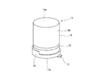
- the electrolytic capacitor 11 is, for example, an aluminum electrolytic capacitor and has a cylindrical shape.
- FIG. 3 shows an example of the electrolytic capacitor 11.
- the thin-walled metal capacitor case 14 has a bottomed cylindrical shape, and the opening surface of the capacitor case 14 is sealed by inserting a cap member (not shown) made of synthetic resin into the opening surface and squeezing it. It has been stopped.
- the concave groove portion 15 over the entire circumference of the capacitor case 14 shown in FIG. 2 is a crimped portion.
- the bottom of the capacitor case 14 is provided with a pedestal 16 made of synthetic resin in order to improve the stability when mounted on the circuit board 3.
- a pair of terminals 17 are provided on the bottom surface 11a of the electrolytic capacitor 11 composed of a cap member (not shown) along the surface of the bottom surface 11a.
- the electrolytic capacitor 11 is fixed to the circuit board 3 by soldering the pair of terminals 17 to a land portion (not shown) provided on the first surface 3A of the circuit board 3.
- the electrolytic capacitor 11 having a cylindrical shape is attached in such a posture that the central axis of the electrolytic capacitor 11 is orthogonal to the first surface 3A.
- the electrolytic capacitor 11 is arranged at a position offset from the center of the circuit board 3 to one side.
- the electrolytic capacitor 11 is relatively small (for example, having a diameter of 8 mm or less), and is an explosion-proof mechanism that releases the internal pressure (in other words, the internal gas) when the internal pressure of the capacitor case 14 rises abnormally. (Not shown) is provided on the bottom surface 11a. In the mounted state, the bottom surface 11a provided with the explosion-proof mechanism faces the first surface 3A of the circuit board 3.
- FIG. 2 is a plan view of the body 4 constituting the housing 2 as viewed from the opening surface side.
- a substrate support portion 21 is formed in a frame shape over the entire circumference at a position recessed from the joint surface with the cover 5 on the peripheral edge of the body 4.
- the circuit board 3 is supported in a state of being placed on the board support portion 21, and is fixed by a plurality of screws (not shown) screwed to the board support portion 21.
- the peripheral edge (end region) of the first surface 3A of the circuit board 3 is in contact with the support surface 21a of the substrate support portion 21.
- a pocket portion 22 is formed in a portion of the bottom surface 4a of the body 4 facing the electrolytic capacitor 11 so as to accommodate the electrolytic capacitor 11.
- the pocket portion 22 of the electrolytic capacitor 11 accommodates almost the entire electrolytic capacitor 11 (for example, a portion on the tip side of the concave groove portion 15) with a slight gap between the electrolytic capacitor 11 and the capacitor case 14. It is formed as a cylindrical recess with a diameter slightly larger than the diameter. Further, the depth is set so that a slight gap is similarly formed between the bottom surface 22a of the pocket portion 22 and the top surface 14a of the capacitor case 14.
- the inner peripheral surface 22b of the pocket portion 22 and the outer peripheral surface 14b of the capacitor case 14 face each other with a slight gap, and the bottom surface 22a of the pocket portion 22 and the top surface 14a of the capacitor case 14 pass through a slight gap. Facing.
- thermal paste 23 is filled.
- the thermal paste 23 is obtained by filling the pocket portion 22 with an appropriate amount in advance before inserting the electrolytic capacitor 11 into the pocket portion 22, and the filling amount is set with some allowance in mind.
- the excess thermal paste 23 overflows from the pocket portion 22 and also covers the bottom portion of the electrolytic capacitor 11.
- the excess thermal paste 23 overflowing from the pocket portion 22 is indicated by reference numeral 23a.
- the excess thermal paste 23a reaches, for example, the first surface 3A of the circuit board 3.
- the pocket portion 22 and the thermal paste 23 are not always essential. Further, even when the thermal paste 23 is provided, the bottom portion of the electrolytic capacitor 11 can be configured not to be covered with the thermal paste 23 by relatively reducing the filling amount to the pocket portion 22.
- the thermal paste 23 instead of the heat radiating grease 23, another type of heat transfer member such as a heat radiating sheet may be used.
- the bottom surface 4a of the body 4 excluding the pocket portion 22 is located closer to the circuit board 3 than the bottom surface 22a of the pocket portion 22.
- the bottom surface 4a is simplified and drawn as a flat surface, but of course, it may include an uneven shape.
- the pocket portion 22 can also be configured by providing a cylindrical wall portion protruding from the bottom surface of the body 4.
- the electrolytic capacitor 11 which is a heat generating component in the pocket portion 22 and filling the heat radiation grease 23 in this way, the heat of the electrolytic capacitor 11 is effectively dissipated to the body 4 side. Therefore, for example, when the body 4 is cooled by the outside air, the electrolytic capacitor 11 is surely cooled.
- the second surface 3B of the circuit board 3 is adjacent to the inner surface of the cover 5, and the heat transfer grease 24 is interposed as a heat transfer member in the gap between the two.
- a heat radiating sheet or the like can also be used as the heat transfer member.
- the circuit board 3 is provided with a gas passage 31 for guiding the gas to a relatively wide internal space or external space of the housing 2 when the explosion-proof mechanism of the electrolytic capacitor 11 is opened and gas is discharged from the inside. ing.
- FIG. 4 is an enlarged view of a main part of FIG. 1 showing the configuration of the gas passage 31, and FIG. 5 is an enlarged cross-sectional view of the circuit board 3 along the line AA in FIG.
- the gas passage 31 passes through the first passage 32 formed along the thickness direction of the circuit board 3 at the mounting position of the electrolytic capacitor 11 of the circuit board 3 and the inside of the circuit board 3. It includes a second passage 33 formed along the first surface 3A.
- the second passage 33 In the second passage 33, one end 33a intersects with the first passage 32 and opens or communicates with the first passage 32, and the other end 33b opens at the end surface 3C of the circuit board 3.
- the second passage 33 extends linearly in a plan view, and is connected to the end surface 3C in a plan view so as to connect the first passage 32 and the end surface 3C of the circuit board 3 at the shortest distance. It is orthogonal.
- the second passage 33 does not necessarily have to be linear, and may be, for example, an L-shaped curved shape or a curved shape in a plan view.
- the second passage 33 is, for example, a passage having a circular cross section. It may have a cross-sectional shape other than a circular shape.
- the second passage 33 is formed in the laminating process of the circuit board 3 which is a multi-layer laminated board.
- the first passage 32 is formed as a circular hole penetrating the circuit board 3 in the thickness direction.
- the first passage 32 is secondarily machined, for example, after the circuit board 3 which is a multilayer laminated board is manufactured. If processing is possible, the first passage 32 may be a sealing hole in which the second surface 3B side is sealed instead of the through hole.
- the first passage 32 is formed as a through hole, but the end portion on the second surface 3B side is substantially closed by the inner surface of the cover 5 via the thermal paste 24.
- the first passage 32 is located corresponding to the gas discharge position of the explosion-proof mechanism of the electrolytic capacitor 11, but even if the positions of the two are not exactly the same, the gas emitted from the explosion-proof mechanism is the first. It suffices if it is in a positional relationship that flows into the passage 32 of.
- the first passage 32 may be open within the range of the circle where the bottom surface 11a of the electrolytic capacitor 11 is projected onto the first surface 3A.
- the first passage 32 and the second passage 33 in this way, when the gas is discharged from the explosion-proof mechanism of the bottom surface 11a of the electrolytic capacitor 11, this gas is applied to the heat radiation grease 23 around the electrolytic capacitor 11. It flows into the first passage 32 without being hindered, and is discharged from the end surface 3C of the circuit board 3 into the relatively narrow space 35 between the end surface 3C and the body 4 through the second passage 33.
- the support surface 21a of the substrate support portion 21 can finally guide the gas to the wider space 36 formed between the circuit board 3 and the bottom surface 4a of the body 4.
- a concave groove 34 is formed in the end region of the first surface 3A in contact with the surface.
- the concave groove 34 is formed in parallel with the second linear passage 33. Similar to the first passage 32, the concave groove 34 is secondarily machined, for example, after the circuit board 3 is manufactured.
- the concave groove 34 having a V-shaped cross section is drawn in FIG. 5, the cross-sectional shape of the concave groove 34 may be any shape.
- the concave groove 34 is formed to have a length from the end surface 3C of the circuit board 3 to at least the space 36. That is, the concave groove 34 crosses the contact portion (contact surface range between the two) between the circuit board 3 and the board support portion 21.
- the concave groove 34 allows the space 35 facing the end surface 3C of the circuit board 3 and the space 36 wider than this to communicate with each other. Therefore, when the gas is discharged from the electrolytic capacitor 11, the gas or pressure is finally released into the relatively wide space 36 in the housing 2.
- the concave groove 34 is unnecessary.
- a concave groove may be provided on the substrate support portion 21 side.
- the circuit board 3 of the embodiment is a so-called four-layer structure printed wiring board provided with a four-layer metal foil layer 41 (for example, a copper foil layer).
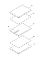
- FIG. 6 is a cross-sectional view showing the layer structure of the circuit board 3 in an exploded manner
- FIG. 7 is a perspective view showing the layer structure of the circuit board 3 in an exploded manner.
- the circuit board 3 has a core laminated board 42 located at the center in the thickness direction (stacking direction), a first exterior laminated board 43 located on the first surface 3A side, and a second. It is roughly composed of a second exterior laminated plate 44 located on the surface 3B side.
- the core laminated plate 42 has a metal foil layer 41 (second metal foil layer 41b and third metal foil layer 41c) attached to both sides of a base material layer 42a such as glass epoxy.
- the metal foil layer 41 (first metal foil layer 41a) is attached to one surface of the base material layer 43a such as glass epoxy in the first exterior laminated plate 43, and the second exterior laminated plate 44 is similarly attached.
- a metal foil layer 41 (fourth metal foil layer 41d) is attached to one surface of a base material layer 44a such as glass epoxy.
- the laminated plates 42, 43, and 44 are stacked via the sheet-shaped prepregs 45, 46, respectively, and are integrated by heating and pressurizing.
- the metal foil layer 41 is formed in a desired wiring pattern (including a land portion and the like) by an appropriate etching method or the like. At least, for the second metal leaf layer 41b and the third metal leaf layer 41c, which are the internal metal leaf layers, a wiring pattern is formed before laminating via the prepregs 45 and 46.
- only the metal foil may be laminated on the central core laminating plate 42 via the prepreg.
- the second passage 33 is notched in the core laminated plate 42 in advance before laminating the circuit board 3.
- the second metal leaf layer 41b and the third metal leaf layer 41c do not have a wiring pattern in the vicinity of the portion where the slit serving as the second passage 33 is formed. That is, the metal foil layer 41 is in a state of being removed by etching or the like, and therefore, the slit serving as the second passage 33 is substantially formed in the base material layer 42a in the core laminated plate 42. There is.
- the second passage 33 is formed in a passage shape. Slit. If necessary, a metal rod-shaped jig is arranged in the slit and laminated so that the prepregs 45 and 46 softened during the laminating process do not enter the slit and block the second passage 33. The jig may be removed (for example, pulled out) after cooling and solidifying by performing a heating and pressurizing treatment in the step.
- the second passage 33 or the like through which gas flows when the explosion-proof mechanism is opened and the wiring pattern of the metal foil layer 41 are located close to each other, there is a concern that the wiring pattern may be corroded by the components contained in the gas. There is. Therefore, it is desirable that there is a certain distance between the passage through which the gas flows and the wiring pattern.
- a wiring pattern is provided in any of the metal leaf layers 41 in the region overlapping with the second passage 33. do not have.
- the second passage 33 is positioned so as to overlap the second passage 33 when projected in the thickness direction of the circuit board 3.
- Circuit board 3 There may be a wiring pattern on the surface layer.
- the explosion-proof mechanism of the electrolytic capacitor 11 when the explosion-proof mechanism of the electrolytic capacitor 11 is opened and the gas is discharged, the gas is guided from the bottom surface 11a of the electrolytic capacitor 11 to a relatively wide space 36 in the housing 2. can do.
- the inside of the housing 2 since the gas is guided through the gas passage 31 including the second passage 33 along the surfaces 3A and 3B of the circuit board 3, the inside of the housing 2 is not limited to the arrangement position of the electrolytic capacitor 11.
- the gas can be guided to any position to the space or the external space, increasing the degree of freedom in design.
- FIG. 8 is a schematic cross-sectional view of the electronic device 1 of the second embodiment, as in FIG. 1. Since the basic configuration of the electronic device 1 of the second embodiment is the same as that of the first embodiment, the differences from the first embodiment will be mainly described below.
- the electronic device 1 includes a metal housing 2 and a circuit board 3 housed inside the housing 2.
- the housing 2 includes, for example, a box-shaped body 4 having an open upper surface made of die-cast aluminum alloy, and a cover 5 made of die-cast aluminum alloy or a steel plate attached so as to cover the opening surface of the body 4. , Is equipped.
- the cover 5 also serves as a base plate for the electric motor unit 6, and by attaching the electric motor unit 6 to the body 4, the housing 2 is configured to be substantially sealed.
- the circuit board 3 has, as a main surface, a first surface 3A facing the body 4 side and a second surface 3B facing the cover 5 side, and at least one electrolytic capacitor 11 is on the first surface 3A. It is mounted together with various electronic components 12.
- a connector 8 that collects power supplies and signal lines is arranged on one side surface of the housing 2.
- the connector 8 is exposed to the outside from the housing 2 so that the mating side connector connected to the controller or the like on the vehicle side is inserted, and the synthetic resin tubular portion 9a into which the mating side connector is inserted is inserted. Projects from the side wall surface of the housing 2 along the direction parallel to the surfaces 3A and 3B of the circuit board 3.
- the connector 8 is mounted on the circuit board 3 at the end of the circuit board 3.
- the connector 8 includes a synthetic resin molding portion 9 including a tubular portion 9a and a base portion 9b, and a plurality of metal terminals 10 insert-molded into the base portion 9b of the synthetic resin molding portion 9.
- the tubular portion 9a is opened in a direction parallel to the circuit board 3 so that the mating connector can be inserted and removed along the direction parallel to the circuit board 3.
- the plurality of metal terminals 10 are bent so as to be directed toward the circuit board 3 at locations protruding from the base portion 9b to the inside of the housing 2. That is, each of the metal terminals 10 has a substantially L-shape.
- the end of the metal terminal 10 on the circuit board 3 side is soldered after passing through a through hole (not shown) provided in the circuit board 3, whereby the connector 8 is attached to the circuit board 3. It is attached.
- the connector 8 is mounted on the circuit board 3 with one side surface of the synthetic resin molding portion 9 near the base portion 9b in contact with the first surface 3A of the circuit board 3.
- the second passage 33 passing through the inside of the circuit board 3 is provided at a position overlapping with the connector 8.
- one end 33a intersects with the first passage 32 and opens or communicates with the first passage 32
- the other end 33b is a circuit. It is open at the end surface 3C of the substrate 3.
- a third passage 37 along the thickness direction of the circuit board 3 is formed on the first surface 3A side of the circuit board 3 as a part of the gas passage 31.
- the passage 37 of 3 intersects or opens with the second passage 33.
- a hole 38 connected in series with the third passage 37 is formed through the tubular portion 9a of the synthetic resin molding portion 9 of the connector 8.
- the gas released from the explosion-proof mechanism is guided to the external space inside the connector 8 through the first passage 32 and the second passage 33, and further through the third passage 37 and the hole 38. ..
- the gas passage 31 communicates with the external space through the gap between the two. Therefore, the gas emitted from the electrolytic capacitor 11 can be guided to the external space, and on the other hand, the opening of the hole 38 in the connector 8 causes rainwater to enter from the outside through the gas passage 31. The intrusion of foreign matter is suppressed.
- the open end of the second passage 33 in the end surface 3C may be left open as shown in FIG. 8, or may be sealed by some means.
- the space 36 between the body 4 of the housing 2 and the circuit board 3 is filled with a gel such as a silicone gel that also functions as a heat transfer member, an appropriate synthetic resin material, or the like.
- a gel such as a silicone gel that also functions as a heat transfer member, an appropriate synthetic resin material, or the like.
- the gel 51 is filled in the entire space 36 including the gap between the pocket portion 22 and the electrolytic capacitor 11. Therefore, there is no space inside the housing 2 that can absorb the gas released from the explosion-proof mechanism. Even with such a configuration, according to the second embodiment, it is possible to discharge the gas to the external space.
- the electronic device of the present invention is With the housing
- the circuit board housed in this housing and
- An electrolytic capacitor mounted on the first surface of this circuit board and provided with an explosion-proof mechanism capable of releasing internal pressure on the bottom surface facing the first surface.
- a first passage formed along the thickness direction of the circuit board at the mounting position of the electrolytic capacitor on the circuit board, and
- a second which is formed along the first surface of the circuit board through the inside of the circuit board, one end of which opens into the first passage and the other end of which communicates with the internal space or the external space of the housing.
- the passage and It is equipped with.
- the other end of the second passage is open at the end face of the circuit board.
- the end region of the first surface of the circuit board is in contact with the board contact portion provided inside the housing.
- a concave groove is formed on the first surface so as to cross the substrate contact portion and communicate the second passage with the internal space of the housing.
- the second passage is formed in the base material layer in the circuit board having a laminated structure including the base material layer and the metal foil layer.
- a connector exposed from the housing to the outside is mounted on the end of the circuit board.
- the second passage communicates to the outside through a hole formed in the connector.
- a pocket portion is formed in a portion of the housing facing the electrolytic capacitor so as to accommodate the electrolytic capacitor. Thermal paste is filled between the inner surface of the pocket and the outer surface of the electrolytic capacitor.
- a part of the thermal paste may overflow from the pocket portion and cover the bottom portion of the electrolytic capacitor.
Landscapes
- Engineering & Computer Science (AREA)
- Power Engineering (AREA)
- Microelectronics & Electronic Packaging (AREA)
- Structures For Mounting Electric Components On Printed Circuit Boards (AREA)
Abstract
筐体(2)に回路基板(3)が収容されており、回路基板(3)の第1面(3A)に電解コンデンサ(11)が実装されている。ガス通路(31)として、電解コンデンサ(11)の底面の防爆機構に対応して回路基板(3)の厚さ方向に沿って第1の通路(32)が形成され、回路基板(3)の面(3A,3B)に沿って回路基板(3)の内部を通る第2の通路(33)が形成される。防爆機構が開いてガスが放出された際に、ガスは、第1面(3A)の凹溝(34)を介して、筐体(2)内の空間(35)から広い空間(36)へと案内される。
Description
この発明は、筐体の内部に収容される回路基板に電解コンデンサが実装された電子装置に関する。
電解コンデンサは、一般に、何らかの原因によるケース内部の過剰な圧力の上昇を回避するために、圧力上昇時に内部の圧力を放出可能な防爆機構(防爆弁とも呼ばれる)を備えている。比較的大型の電解コンデンサではケースの頂面に防爆弁を備えることが多く、比較的小型の電解コンデンサでは、ケースの底面に例えば端子の導出部などを利用した防爆機構が設けられることが多い。
特許文献1には、後者のようにケースの底面に防爆機構を備えた電解コンデンサを回路基板に実装するに際して、回路基板の防爆機構に対応する位置に貫通孔を形成し、防爆機構により排出されたガスがこの貫通孔を介して回路基板の背面(電解コンデンサの実装面と反対側の面)側の空間に放出されるようにした構成が開示されている。電解コンデンサのケースの頂面は、電解コンデンサの冷却(放熱)を図るために、絶縁シートを介して筐体の内側面に圧接した構成となっている。
ケースの底面に防爆機構を備えた電解コンデンサでは、基本的にケース底面から回路基板の電解コンデンサ実装面に沿ってガスが放出されることとなるが、電解コンデンサに近接して放熱グリス等の伝熱部材が設けられたような場合に、ガスの放出が困難である。
一方、回路基板に貫通孔を設けた特許文献1の構成では、回路基板の背面が筐体の内側面に近接している場合や、放熱シートや放熱グリスが回路基板背面に配置されたような場合に、ガスの放出経路を十分に確保できない。
本発明によれば、その1つの態様において、電子装置は、回路基板の第1の面に実装され、該第1の面に向かう底面に、内部の圧力を放出可能な防爆機構が設けられた電解コンデンサと、上記回路基板の上記電解コンデンサの実装位置に、当該回路基板の厚さ方向に沿って形成された第1の通路と、上記回路基板の内部を通して当該回路基板の上記第1の面に沿って形成され、一端が上記第1の通路に開口するとともに他端が上記筐体の内部空間もしくは外部空間に連通した第2の通路と、を備えている。
上記構成では、電解コンデンサの防爆機構からガスが放出された際に、第1の通路から回路基板内部の回路基板の面に沿って延びる第2の通路を通して電解コンデンサから離れた任意の位置へガスが導かれる。従って、設計の自由度が高くなり、かつ確実なガスの放出が可能となる。
以下、この発明の一実施例の電子装置1について、図面に基づいて詳細に説明する。
図1は、第1実施例の電子装置1の概略的な断面図であり、図4は、図1の要部を拡大して示す断面図である。この電子装置1は、例えば自動車用内燃機関の吸気弁もしくは排気弁のバルブタイミングを変更する可変バルブタイミング機構のコントローラを構成している。この電子装置1は、金属製の筐体2と、この筐体2の内部に収容された回路基板3と、を備えている。
筐体2は、例えばアルミニウム合金のダイキャストからなる上面が開口した箱状をなすボディ4と、このボディ4の開口面を覆うように取り付けられるアルミニウム合金のダイキャストもしくは鋼板などからなるカバー5と、から構成される。この実施例では、カバー5は、電動モータ部6のベースプレートを兼ねており、ボディ4に電動モータ部6を取り付けることで筐体2が実質的に密閉された状態に構成されるようになっている。電動モータ部6の中心部にはボディ4とは反対側へ突出した回転軸7が位置しており、この回転軸7に図示しない減速機が同軸状に連結される。これらの電子装置1、電動モータ部6および減速機によって、いわゆる機電一体型の可変バルブタイミング機構が構成されている。
回路基板3は、主面として、ボディ4側へ向かう第1面3Aと、カバー5側へ向かう第2面3Bと、を有する。第1面3Aには、少なくとも1つの電解コンデンサ11が他の種々の電子部品12とともに実装されている。第2面3Bは、基本的に回路パターンのみを具備しており、電子部品は実装されていない。あるいは、第2面3Bに、図示しない小型の電子部品が実装されていてもよい。
筐体2の一つの側面には、電源や信号ラインをまとめたコネクタ8が配置されている。このコネクタ8は、車両側のコントローラ等に接続されている相手側コネクタが挿入されるように筐体2から外部へ露出しており、相手側コネクタが挿入される合成樹脂製の筒状部9a(図8参照)が筐体2の側壁面から回路基板3の面3A,3Bと平行な方向へ沿って突出している。このコネクタ8は、後述するように回路基板3の端部において該回路基板3に実装されている。
電解コンデンサ11は、例えばアルミ電解コンデンサであり、円筒形をなしている。図3は、電解コンデンサ11の一例を示している。薄肉な金属製のコンデンサケース14は、有底円筒状をなし、その開口面に合成樹脂製のキャップ部材(図示せず)を挿入しかつかしめ加工することで、コンデンサケース14の開口面が封止されている。図2に示すコンデンサケース14の全周に亘る凹溝部15が、かしめ加工された箇所である。また、コンデンサケース14の底部には、回路基板3に実装した際の安定性を高めるために、合成樹脂製の台座16を備えている。図示しないキャップ部材により構成される電解コンデンサ11の底面11aには、一対の端子17が該底面11aの面に沿った形で設けられている。この一対の端子17が回路基板3の第1面3Aに設けられたランド部(図示せず)にハンダ付けされることで、電解コンデンサ11は、回路基板3に固定されている。詳しくは、円筒形をなす電解コンデンサ11の中心軸線が第1面3Aと直交するような姿勢で取り付けられている。
図1の例では、回路基板3の中心部から一方へ片寄った位置に電解コンデンサ11が配置されている。
電解コンデンサ11は、比較的小型(例えば直径8mm以下)のものであり、コンデンサケース14の内部の圧力が異常に上昇したときに、内部の圧力(換言すれば内部のガス)を放出する防爆機構(図示せず)を底面11aに備えている。取付状態では、防爆機構を備えた底面11aは、回路基板3の第1面3Aへ向かっている。
図2は、筐体2を構成するボディ4を開口面側から見た平面図である。この図2および図1の断面図に示すように、ボディ4の周縁には、カバー5との接合面から凹んだ位置に全周に亘って枠状に基板支持部21が形成されている。回路基板3は、この基板支持部21の上に載った状態に支持されており、基板支持部21に螺合する図示しない複数のネジによって固定されている。このようにボディ4に取り付けられた状態では、回路基板3の第1面3Aの周縁(端部領域)が基板支持部21の支持面21aに接した状態となっている。
また、図1および図2に示すように、ボディ4の底面4aにおける電解コンデンサ11と対向する部位に、電解コンデンサ11を収容するようにポケット部22が形成されている。このポケット部22は、電解コンデンサ11のコンデンサケース14との間に僅かな間隙を介して電解コンデンサ11のほぼ全体(例えば凹溝部15よりも先端側部分)を収容するように、電解コンデンサ11の径よりも僅かに大きな口径の円筒形の凹部として形成されている。また、その深さは、ポケット部22の底面22aとコンデンサケース14の頂面14aとの間に同様に僅かな間隙が生じるように設定されている。従って、ポケット部22の内周面22bとコンデンサケース14の外周面14bとは僅かな間隙を介して対向し、ポケット部22の底面22aとコンデンサケース14の頂面14aとは僅かな間隙を介して対向する。
そして、これらのポケット部22の内周面22bとコンデンサケース14の外周面14bとの間の間隙およびポケット部22の底面22aとコンデンサケース14の頂面14aとの間の間隙には、伝熱部材例えば放熱グリス23が充填されている。この放熱グリス23は、電解コンデンサ11をポケット部22内に挿入する前に予め適当量をポケット部22内に充填したものであり、多少の余裕を見込んで充填量が設定されることから、図1の例では、余剰の放熱グリス23がポケット部22から溢れて、電解コンデンサ11の底部をも覆っている。図1には、ポケット部22から溢れた余剰の放熱グリス23が符号23aでもって示されている。余剰の放熱グリス23aは、例えば、回路基板3の第1面3Aに達している。
なお、本発明においては、ポケット部22および放熱グリス23は必ずしも必須のものではない。また、放熱グリス23を設ける場合でも、ポケット部22への充填量を比較的少なくすることで、電解コンデンサ11の底部が放熱グリス23に覆われていない構成とすることができる。放熱グリス23に代えて放熱シート等の他の形式の伝熱部材を用いてもよい。
図示例では、ポケット部22を除くボディ4の底面4aは、ポケット部22の底面22aよりも回路基板3に近い位置にある。図では、底面4aが平面として単純化されて描かれているが、勿論、凹凸形状を含んでいてもよい。また、ポケット部22は、ボディ4の底面から突出した円筒状の壁部を設けることで構成することもできる。
このように発熱部品である電解コンデンサ11をポケット部22内に収容しかつ放熱グリス23を充填することで、電解コンデンサ11の熱が効果的にボディ4側へ放熱される。従って、例えばボディ4が外気により冷却作用を受けることで、電解コンデンサ11が確実に冷却される。
回路基板3の第2面3Bは、カバー5の内側面に隣接しており、両者間の間隙には、伝熱部材として放熱グリス24が介在している。なお、伝熱部材として放熱シート等を用いることもできる。
回路基板3には、電解コンデンサ11の防爆機構が開いて内部からガスが放出された際に、このガスを筐体2の比較的広い内部空間もしくは外部空間へ導くためのガス通路31が設けられている。
図4は、ガス通路31の構成を示す図1の要部の拡大図であり、図5は、図4におけるA-A線に沿った回路基板3の拡大断面図である。これらの図に示すように、ガス通路31は、回路基板3の電解コンデンサ11の実装位置において回路基板3の厚さ方向に沿って形成された第1の通路32と、回路基板3の内部を通して第1面3Aに沿って形成された第2の通路33と、を含んでいる。
第2の通路33は、一端33aが第1の通路32と交差して該第1の通路32に開口ないし連通し、かつ、他端33bが回路基板3の端面3Cにおいて開口している。図示例では、第2の通路33は、平面視で直線状に延びており、第1の通路32と回路基板3の端面3Cとの間を最短距離で結ぶように、平面視で端面3Cに直交している。但し、本発明においては、第2の通路33は必ずしも直線状でなくてもよく、例えば平面視でL字形に屈曲した形状や曲線状などであってもよい。図5に示すように、第2の通路33は、例えば断面円形の通路である。円形以外の断面形状であってもよい。後述するように、第2の通路33は、多層積層基板である回路基板3の積層工程の中で形成される。
また、第1の通路32は、図示例では、回路基板3を厚さ方向に貫通した円形の孔として形成されている。第1の通路32は、例えば、多層積層基板である回路基板3の製造後に二次的に機械加工される。加工が可能であれば、第1の通路32は、貫通孔ではなく第2面3B側が封止された封止孔であってもよい。図示例は、第1の通路32が貫通孔として形成されているが、第2面3B側の端部は、放熱グリス24を介してカバー5の内側面によって実質的に塞がれている。第1の通路32は、電解コンデンサ11の防爆機構のガス排出位置に対応して位置することが望ましいが、両者の位置が厳密に一致していなくても、防爆機構から出たガスが第1の通路32に流れ込む位置関係にあればよい。例えば、電解コンデンサ11の底面11aを第1面3Aに投影した円の範囲内に第1の通路32が開口していればよい。
このように第1の通路32および第2の通路33を備えることで、電解コンデンサ11の底面11aの防爆機構からガスが放出された際に、このガスは、電解コンデンサ11周囲の放熱グリス23に妨げられることなく第1の通路32に流入し、かつ第2の通路33を通って、回路基板3の端面3Cから該端面3Cとボディ4との間の比較的狭い空間35に排出される。
さらに、図示の第1実施例では、回路基板3とボディ4の底面4aとの間に形成されるより広い空間36に最終的にガスを案内し得るように、基板支持部21の支持面21aに接する第1面3Aの端部領域に、凹溝34が形成されている。図示例では、直線状をなす第2の通路33と平行に凹溝34が形成されている。この凹溝34は、第1の通路32と同様に、例えば、回路基板3の製造後に二次的に機械加工される。図5には、断面V字形をなす凹溝34が描かれているが、凹溝34の断面形状はどのような形状であってもよい。
凹溝34は、回路基板3の端面3Cから少なくとも空間36に達するまでの長さに形成されている。つまり、凹溝34は、回路基板3と基板支持部21との当接部(両者の接触面範囲)を横切っている。この凹溝34によって、回路基板3の端面3Cが面する空間35とこれよりも広い空間36とが互いに連通している。従って、電解コンデンサ11からガスが放出された際には、最終的にガスないし圧力が筐体2内の比較的広い空間36に開放されることとなる。
なお、回路基板3の端面3Cに面する空間35(つまり回路基板3の周縁に残存する空間35)の容積が電解コンデンサ11の容量に対して十分に大きい場合には、凹溝34は不要である。あるいは、回路基板3の凹溝34に代えて、基板支持部21側に凹溝を設けるようにしてもよい。
次に、図5~図7を参照して、第2の通路33の形成方法の一例を説明する。図5に示すように、実施例の回路基板3は、4層の金属箔層41(例えば銅箔層)を備えたいわゆる4層構造のプリント配線基板である。図6は、回路基板3の層構造を分解して示した断面図、図7は、回路基板3の層構造を分解して示した斜視図である。
図6および図7に示すように、回路基板3は、厚さ方向(積層方向)中央に位置するコア積層板42と、第1面3A側に位置する第1外装積層板43と、第2面3B側に位置する第2外装積層板44と、から大略構成されている。コア積層板42は、ガラスエポキシ等の基材層42aの両面に金属箔層41(第2金属箔層41bおよび第3金属箔層41c)がそれぞれ貼着されている。第1外装積層板43は、ガラスエポキシ等の基材層43aの一方の面に金属箔層41(第1金属箔層41a)が貼着されており、第2外装積層板44は、同様に、ガラスエポキシ等の基材層44aの一方の面に金属箔層41(第4金属箔層41d)が貼着されている。そして、これらの積層板42,43,44は、それぞれシート状のプリプレグ45,46を介して重ねられ、かつ加熱加圧することで、一体化されている。金属箔層41は、適宜なエッチング法等により所望の配線パターン(ランド部等を含む)に形成されている。少なくとも、内部金属箔層となる第2金属箔層41bおよび第3金属箔層41cについては、プリプレグ45,46を介した積層前に配線パターンの形成が行われる。
なお、回路基板3の他の積層方法として、中心のコア積層板42にプリプレグを介して金属箔のみを積層していくようにしてもよい。
ここで、上記の第2の通路33は、図7に示すように、回路基板3の積層前に予めコア積層板42にスリット状に切欠形成される。この第2の通路33となるスリットが形成される箇所の近傍では、第2金属箔層41bおよび第3金属箔層41cは配線パターンを具備していない。つまり、金属箔層41がエッチング等により取り除かれた状態となっており、従って、第2の通路33となるスリットは、実質的にはコア積層板42の中の基材層42aに形成されている。
このようにスリットを具備したコア積層板42の両側にプリプレグ45,46とともに第1外装積層板43および第2外装積層板44が積層されることで、第2の通路33が通路状に形成される。なお、積層工程中に軟化したプリプレグ45,46がスリット内に進入して第2の通路33を塞いでしまわないように、必要に応じて、金属棒状の治具をスリット内に配置して積層工程における加熱加圧処理を行い、冷却固化後にこの治具を除去(例えば、引き抜き)するようにしてもよい。
ところで、防爆機構が開いた際にガスが流れる第2の通路33等と金属箔層41の配線パターンとが互いに近くに位置していると、ガスに含まれる成分によって配線パターンの腐食が生じる懸念がある。そのため、ガスが流れる通路と配線パターンとの間に、ある一定の距離があることが望ましい。例えば一つの例では、第2の通路33を回路基板3の厚さ方向に投影したときに、第2の通路33と重なる領域には、いずれの金属箔層41においても配線パターンが設けられていない。ガスによる腐食の観点からは、第1の通路32についても、その周囲には配線パターンを設けないことが望ましく、例えば、電解コンデンサ11の径と同程度の円内には、第2,第3,第4金属箔層41b,41c,41dは配線パターンを具備していない。
なお、表層の配線パターンはガスによる影響を受けにくいので、本発明においては、第2の通路33を回路基板3の厚さ方向に投影したときに第2の通路33と重なることとなる位置に、回路基板3表層の配線パターンがあってもよい。
以上のように、上記実施例によれば、電解コンデンサ11の防爆機構が開いてガスが放出された際に、電解コンデンサ11の底面11aから筐体2内の比較的広い空間36にガスを案内することができる。特に、回路基板3の面3A,3Bに沿った第2の通路33を含むガス通路31を介してガスが案内されるので、電解コンデンサ11の配置位置に制限されずに、筐体2の内部空間もしくは外部空間へと任意の位置にガスを案内でき、設計の自由度が高くなる。
次に、図8に基づいて本発明の第2実施例を説明する。図8は、図1と同様に、第2実施例の電子装置1の概略的な断面図である。この第2実施例の電子装置1の基本的な構成は、第1実施例のものと変わりがないので、以下では、主に第1実施例との相違点について説明する。
前述したように、この電子装置1は、金属製の筐体2と、この筐体2の内部に収容された回路基板3と、を備えている。
筐体2は、例えばアルミニウム合金のダイキャストからなる上面が開口した箱状をなすボディ4と、このボディ4の開口面を覆うように取り付けられるアルミニウム合金のダイキャストもしくは鋼板などからなるカバー5と、を備えている。カバー5は、電動モータ部6のベースプレートを兼ねており、ボディ4に電動モータ部6を取り付けることで筐体2が実質的に密閉された状態に構成されるようになっている。
回路基板3は、主面として、ボディ4側へ向かう第1面3Aと、カバー5側へ向かう第2面3Bと、を有し、第1面3Aに、少なくとも1つの電解コンデンサ11が他の種々の電子部品12とともに実装されている。
筐体2の一つの側面には、電源や信号ラインをまとめたコネクタ8が配置されている。このコネクタ8は、車両側のコントローラ等に接続されている相手側コネクタが挿入されるように筐体2から外部へ露出しており、相手側コネクタが挿入される合成樹脂製の筒状部9aが筐体2の側壁面から回路基板3の面3A,3Bと平行な方向へ沿って突出している。このコネクタ8は、回路基板3の端部において該回路基板3に実装されている。
すなわち、コネクタ8は、筒状部9aおよびベース部9bを含む合成樹脂成形部9と、この合成樹脂成形部9のベース部9bにインサート成形された複数の金属端子10と、を含んでいる。筒状部9aは、回路基板3と平行な方向に沿って相手側コネクタが抜き差しできるように、回路基板3と平行な方向へ向かって開口している。複数の金属端子10は、ベース部9bから筐体2の内側へ出た箇所でそれぞれ回路基板3へ向かうように折れ曲がっている。つまり、金属端子10は、それぞれ略L字形をなしている。そして、金属端子10の回路基板3側の端部は、回路基板3に設けられたスルーホール(図示せず)を貫通した上でハンダ付けされており、これによって、コネクタ8が回路基板3に取り付けられている。詳しくは、合成樹脂成形部9のベース部9b付近の一つの側面が回路基板3の第1面3Aに接した状態でもって、コネクタ8が回路基板3に実装されている。
ここで、第2実施例においては、回路基板3の内部を通る第2の通路33がコネクタ8と重なる位置に設けられている。第2の通路33は、前述した第1実施例のものと同様に、一端33aが第1の通路32と交差して該第1の通路32に開口ないし連通し、かつ、他端33bが回路基板3の端面3Cにおいて開口している。そして、他端33bの近傍において、ガス通路31の一部として、回路基板3の厚さ方向に沿った第3の通路37が回路基板3の第1面3A側に形成されており、この第3の通路37が第2の通路33に交差ないし開口している。さらに、コネクタ8の合成樹脂成形部9の筒状部9aに、上記第3の通路37に直列に連なる孔38が貫通形成されている。
従って、防爆機構から放出されたガスは、第1の通路32および第2の通路33を通り、さらに第3の通路37および孔38を通って、コネクタ8の内側で外部空間へと案内される。コネクタ8に相手側コネクタが挿入されている状態でも、両者の隙間を通してガス通路31は外部空間に連通している。そのため、電解コンデンサ11から出たガスを外部空間へ案内することができ、かつ一方で、コネクタ8内で孔38が開口していることにより、ガス通路31を介した外部からの雨水の侵入や異物の侵入が抑制される。なお、端面3Cにおける第2の通路33の開口端は、図8のように開口したままでもよく、何らかの手段で封止するようにしてもよい。
この第2実施例は、特に、筐体2のボディ4と回路基板3との間の空間36が、伝熱部材としても機能するシリコーンゲル等のゲルや適宜な合成樹脂材料等で充填された構成に適している。図8の例では、ポケット部22と電解コンデンサ11との間の間隙を含む空間36の全体にゲル51が充填されている。従って筐体2の内部には、防爆機構から放出されたガスを吸収できる空間がない。このような構成でも、上記第2実施例によれば、外部空間へのガスの排出が可能である。
なお、図1に示したようなポケット部22内に放熱グリス23を充填した構成においても、第2実施例の構成を適用することが可能である。
以上のように、この発明の電子装置は、
筐体と、
この筐体に収容された回路基板と、
この回路基板の第1の面に実装され、該第1の面に向かう底面に、内部の圧力を放出可能な防爆機構が設けられた電解コンデンサと、
上記回路基板の上記電解コンデンサの実装位置に、当該回路基板の厚さ方向に沿って形成された第1の通路と、
上記回路基板の内部を通して当該回路基板の上記第1の面に沿って形成され、一端が上記第1の通路に開口するとともに他端が上記筐体の内部空間もしくは外部空間に連通した第2の通路と、
を備えている。
筐体と、
この筐体に収容された回路基板と、
この回路基板の第1の面に実装され、該第1の面に向かう底面に、内部の圧力を放出可能な防爆機構が設けられた電解コンデンサと、
上記回路基板の上記電解コンデンサの実装位置に、当該回路基板の厚さ方向に沿って形成された第1の通路と、
上記回路基板の内部を通して当該回路基板の上記第1の面に沿って形成され、一端が上記第1の通路に開口するとともに他端が上記筐体の内部空間もしくは外部空間に連通した第2の通路と、
を備えている。
好ましい一つの態様では、上記第2の通路は、上記他端が上記回路基板の端面において開口している。
また好ましい一つの態様では、
上記回路基板の上記第1の面の端部領域が上記筐体内部に設けられた基板当接部に接しており、
上記第1の面には、上記基板当接部を横切って上記第2の通路と上記筐体の内部空間とを連通する凹溝が形成されている。
上記回路基板の上記第1の面の端部領域が上記筐体内部に設けられた基板当接部に接しており、
上記第1の面には、上記基板当接部を横切って上記第2の通路と上記筐体の内部空間とを連通する凹溝が形成されている。
好ましい一つの態様では、上記第2の通路は、基材層と金属箔層とを含む積層構造をなす上記回路基板の中で、上記基材層に形成されている。
また、好ましい一つの態様では、
上記筐体から外部へ露出するコネクタが上記回路基板の端部に実装されており、
上記第2の通路は、上記コネクタに形成された孔を介して外部へ連通している。
上記筐体から外部へ露出するコネクタが上記回路基板の端部に実装されており、
上記第2の通路は、上記コネクタに形成された孔を介して外部へ連通している。
また好ましい一つの態様では、上記筐体の上記電解コンデンサと対向する部分に、上記電解コンデンサを収容するようにポケット部が形成されており、
このポケット部の内側面と上記電解コンデンサ外表面との間に放熱グリスが充填されている。
このポケット部の内側面と上記電解コンデンサ外表面との間に放熱グリスが充填されている。
上記放熱グリスの一部が、上記ポケット部から溢れて上記電解コンデンサの底部を覆っていてもよい。
Claims (7)
- 筐体と、
この筐体に収容された回路基板と、
この回路基板の第1の面に実装され、該第1の面に向かう底面に、内部の圧力を放出可能な防爆機構が設けられた電解コンデンサと、
上記回路基板の上記電解コンデンサの実装位置に、当該回路基板の厚さ方向に沿って形成された第1の通路と、
上記回路基板の内部を通して当該回路基板の上記第1の面に沿って形成され、一端が上記第1の通路に開口するとともに他端が上記筐体の内部空間もしくは外部空間に連通した第2の通路と、
を備えてなる電子装置。 - 上記第2の通路は、上記他端が上記回路基板の端面において開口している、請求項1に記載の電子装置。
- 上記回路基板の上記第1の面の端部領域が上記筐体内部に設けられた基板当接部に接しており、
上記第1の面には、上記基板当接部を横切って上記第2の通路と上記筐体の内部空間とを連通する凹溝が形成されている、請求項2に記載の電子装置。 - 上記第2の通路は、基材層と金属箔層とを含む積層構造をなす上記回路基板の中で、上記基材層に形成されている、請求項1~3のいずれかに記載の電子装置。
- 上記筐体から外部へ露出するコネクタが上記回路基板の端部に実装されており、
上記第2の通路は、上記コネクタに形成された孔を介して外部へ連通している、
請求項1に記載の電子装置。 - 上記筐体の上記電解コンデンサと対向する部分に、上記電解コンデンサを収容するようにポケット部が形成されており、
このポケット部の内側面と上記電解コンデンサ外表面との間に放熱グリスが充填されている、
請求項1~5のいずれかに記載の電子装置。 - 上記放熱グリスの一部が、上記ポケット部から溢れて上記電解コンデンサの底部を覆っている、請求項6に記載の電子装置。
Priority Applications (1)
| Application Number | Priority Date | Filing Date | Title |
|---|---|---|---|
| JP2022566957A JPWO2022118880A1 (ja) | 2020-12-02 | 2021-12-01 |
Applications Claiming Priority (2)
| Application Number | Priority Date | Filing Date | Title |
|---|---|---|---|
| JP2020199988 | 2020-12-02 | ||
| JP2020-199988 | 2020-12-02 |
Publications (1)
| Publication Number | Publication Date |
|---|---|
| WO2022118880A1 true WO2022118880A1 (ja) | 2022-06-09 |
Family
ID=81853266
Family Applications (1)
| Application Number | Title | Priority Date | Filing Date |
|---|---|---|---|
| PCT/JP2021/044081 WO2022118880A1 (ja) | 2020-12-02 | 2021-12-01 | 電子装置 |
Country Status (2)
| Country | Link |
|---|---|
| JP (1) | JPWO2022118880A1 (ja) |
| WO (1) | WO2022118880A1 (ja) |
Citations (6)
| Publication number | Priority date | Publication date | Assignee | Title |
|---|---|---|---|---|
| JPH0178018U (ja) * | 1987-11-12 | 1989-05-25 | ||
| JPH07220708A (ja) * | 1994-01-28 | 1995-08-18 | Shin Kobe Electric Mach Co Ltd | 電子,電気機器収納用電池及び電子,電気機器 |
| JP2005174950A (ja) * | 2003-12-05 | 2005-06-30 | Toyota Industries Corp | 電解コンデンサの実装構造 |
| JP2011065906A (ja) * | 2009-09-18 | 2011-03-31 | Panasonic Corp | 電池モジュール |
| JP2016197683A (ja) * | 2015-04-06 | 2016-11-24 | 株式会社デンソー | 電子制御装置 |
| WO2020144922A1 (ja) * | 2019-01-08 | 2020-07-16 | 日立オートモティブシステムズ株式会社 | 電子制御装置 |
-
2021
- 2021-12-01 JP JP2022566957A patent/JPWO2022118880A1/ja active Pending
- 2021-12-01 WO PCT/JP2021/044081 patent/WO2022118880A1/ja active Application Filing
Patent Citations (6)
| Publication number | Priority date | Publication date | Assignee | Title |
|---|---|---|---|---|
| JPH0178018U (ja) * | 1987-11-12 | 1989-05-25 | ||
| JPH07220708A (ja) * | 1994-01-28 | 1995-08-18 | Shin Kobe Electric Mach Co Ltd | 電子,電気機器収納用電池及び電子,電気機器 |
| JP2005174950A (ja) * | 2003-12-05 | 2005-06-30 | Toyota Industries Corp | 電解コンデンサの実装構造 |
| JP2011065906A (ja) * | 2009-09-18 | 2011-03-31 | Panasonic Corp | 電池モジュール |
| JP2016197683A (ja) * | 2015-04-06 | 2016-11-24 | 株式会社デンソー | 電子制御装置 |
| WO2020144922A1 (ja) * | 2019-01-08 | 2020-07-16 | 日立オートモティブシステムズ株式会社 | 電子制御装置 |
Also Published As
| Publication number | Publication date |
|---|---|
| JPWO2022118880A1 (ja) | 2022-06-09 |
Similar Documents
| Publication | Publication Date | Title |
|---|---|---|
| EP2107864B1 (en) | Control device | |
| US5672414A (en) | Multilayered printed board structure | |
| TW200601926A (en) | Printed circuit board and manufacturing method thereof | |
| US20030161491A1 (en) | Electret capacitor microphone | |
| JP2011243870A (ja) | コイル実装基板 | |
| WO2007013239A1 (ja) | 積層型電子部品、電子装置および積層型電子部品の製造方法 | |
| JP2017163810A (ja) | 電動モータ制御装置 | |
| WO2022118880A1 (ja) | 電子装置 | |
| JP2007174635A (ja) | マイクロホンパッケージの製造方法及びマイクロホンパッケージ | |
| JP3556121B2 (ja) | 電動式パワーステアリング回路装置 | |
| WO2011102468A1 (ja) | 車載電気接続箱、及びこれに用いられる回路材、回路ユニット | |
| JP2007134612A (ja) | コンデンサ | |
| WO2016117441A1 (ja) | コンデンサ構造 | |
| US10098267B1 (en) | Housing for a camera and method of manufacture | |
| US20090294052A1 (en) | Method For Fabricating Component-Embedded Printed Circuit Board | |
| WO2022064842A1 (ja) | 基板ユニット | |
| US20040066602A1 (en) | Electronic control device and manufacturing method for the same | |
| WO2020144922A1 (ja) | 電子制御装置 | |
| JPH0682922B2 (ja) | 金属プリント配線基板の製造方法 | |
| WO2020202954A1 (ja) | 電子部品の実装構造、及び電子部品の実装構造の製造方法 | |
| US20110048777A1 (en) | Component-Embedded Printed Circuit Board | |
| JP6046063B2 (ja) | 基板 | |
| JP7010001B2 (ja) | 電子装置 | |
| CN112352298B (zh) | 电子装置 | |
| WO2014208006A1 (ja) | 電子装置およびその電子装置の製造方法 |
Legal Events
| Date | Code | Title | Description |
|---|---|---|---|
| 121 | Ep: the epo has been informed by wipo that ep was designated in this application |
Ref document number: 21900631 Country of ref document: EP Kind code of ref document: A1 |
|
| ENP | Entry into the national phase |
Ref document number: 2022566957 Country of ref document: JP Kind code of ref document: A |
|
| NENP | Non-entry into the national phase |
Ref country code: DE |
|
| 122 | Ep: pct application non-entry in european phase |
Ref document number: 21900631 Country of ref document: EP Kind code of ref document: A1 |