WO2022118712A1 - Cartouche de médicament, cassette, dispositif d'injection de médicament et système d'injection de médicament - Google Patents
Cartouche de médicament, cassette, dispositif d'injection de médicament et système d'injection de médicament Download PDFInfo
- Publication number
- WO2022118712A1 WO2022118712A1 PCT/JP2021/043006 JP2021043006W WO2022118712A1 WO 2022118712 A1 WO2022118712 A1 WO 2022118712A1 JP 2021043006 W JP2021043006 W JP 2021043006W WO 2022118712 A1 WO2022118712 A1 WO 2022118712A1
- Authority
- WO
- WIPO (PCT)
- Prior art keywords
- drug
- temperature
- cassette
- injection device
- information
- Prior art date
Links
- 239000003814 drug Substances 0.000 title claims abstract description 736
- 229940079593 drug Drugs 0.000 title claims abstract description 719
- 239000007924 injection Substances 0.000 title claims description 499
- 238000002347 injection Methods 0.000 title claims description 499
- 239000007788 liquid Substances 0.000 claims abstract description 35
- 230000004044 response Effects 0.000 claims abstract description 6
- 238000001514 detection method Methods 0.000 claims description 74
- 230000001133 acceleration Effects 0.000 claims description 29
- 230000005540 biological transmission Effects 0.000 claims description 27
- 238000012546 transfer Methods 0.000 claims description 19
- 238000001802 infusion Methods 0.000 claims description 17
- 238000003860 storage Methods 0.000 claims description 15
- 230000005856 abnormality Effects 0.000 claims description 7
- 239000003795 chemical substances by application Substances 0.000 claims description 6
- 238000004364 calculation method Methods 0.000 claims description 5
- 238000000926 separation method Methods 0.000 claims description 4
- 230000003287 optical effect Effects 0.000 claims description 3
- 238000003825 pressing Methods 0.000 claims description 3
- 230000000717 retained effect Effects 0.000 abstract description 2
- 239000007787 solid Substances 0.000 description 20
- 230000000740 bleeding effect Effects 0.000 description 19
- 238000010586 diagram Methods 0.000 description 19
- 239000003990 capacitor Substances 0.000 description 16
- 230000007246 mechanism Effects 0.000 description 16
- 238000000034 method Methods 0.000 description 16
- 230000035945 sensitivity Effects 0.000 description 10
- 238000004891 communication Methods 0.000 description 9
- 238000002156 mixing Methods 0.000 description 9
- 230000008569 process Effects 0.000 description 9
- 238000005070 sampling Methods 0.000 description 8
- 230000007423 decrease Effects 0.000 description 5
- 230000006870 function Effects 0.000 description 4
- 238000004590 computer program Methods 0.000 description 3
- 230000006866 deterioration Effects 0.000 description 3
- 230000007613 environmental effect Effects 0.000 description 3
- 238000005259 measurement Methods 0.000 description 3
- 239000000126 substance Substances 0.000 description 3
- 230000008859 change Effects 0.000 description 2
- 230000000694 effects Effects 0.000 description 2
- 230000005684 electric field Effects 0.000 description 2
- 230000020169 heat generation Effects 0.000 description 2
- NOESYZHRGYRDHS-UHFFFAOYSA-N insulin Chemical compound N1C(=O)C(NC(=O)C(CCC(N)=O)NC(=O)C(CCC(O)=O)NC(=O)C(C(C)C)NC(=O)C(NC(=O)CN)C(C)CC)CSSCC(C(NC(CO)C(=O)NC(CC(C)C)C(=O)NC(CC=2C=CC(O)=CC=2)C(=O)NC(CCC(N)=O)C(=O)NC(CC(C)C)C(=O)NC(CCC(O)=O)C(=O)NC(CC(N)=O)C(=O)NC(CC=2C=CC(O)=CC=2)C(=O)NC(CSSCC(NC(=O)C(C(C)C)NC(=O)C(CC(C)C)NC(=O)C(CC=2C=CC(O)=CC=2)NC(=O)C(CC(C)C)NC(=O)C(C)NC(=O)C(CCC(O)=O)NC(=O)C(C(C)C)NC(=O)C(CC(C)C)NC(=O)C(CC=2NC=NC=2)NC(=O)C(CO)NC(=O)CNC2=O)C(=O)NCC(=O)NC(CCC(O)=O)C(=O)NC(CCCNC(N)=N)C(=O)NCC(=O)NC(CC=3C=CC=CC=3)C(=O)NC(CC=3C=CC=CC=3)C(=O)NC(CC=3C=CC(O)=CC=3)C(=O)NC(C(C)O)C(=O)N3C(CCC3)C(=O)NC(CCCCN)C(=O)NC(C)C(O)=O)C(=O)NC(CC(N)=O)C(O)=O)=O)NC(=O)C(C(C)CC)NC(=O)C(CO)NC(=O)C(C(C)O)NC(=O)C1CSSCC2NC(=O)C(CC(C)C)NC(=O)C(NC(=O)C(CCC(N)=O)NC(=O)C(CC(N)=O)NC(=O)C(NC(=O)C(N)CC=1C=CC=CC=1)C(C)C)CC1=CN=CN1 NOESYZHRGYRDHS-UHFFFAOYSA-N 0.000 description 2
- 238000004519 manufacturing process Methods 0.000 description 2
- 238000002844 melting Methods 0.000 description 2
- 230000008018 melting Effects 0.000 description 2
- 102000018997 Growth Hormone Human genes 0.000 description 1
- 108010051696 Growth Hormone Proteins 0.000 description 1
- 102000004877 Insulin Human genes 0.000 description 1
- 108090001061 Insulin Proteins 0.000 description 1
- 238000010009 beating Methods 0.000 description 1
- 230000004397 blinking Effects 0.000 description 1
- 239000004020 conductor Substances 0.000 description 1
- 238000005336 cracking Methods 0.000 description 1
- 238000005520 cutting process Methods 0.000 description 1
- 230000002542 deteriorative effect Effects 0.000 description 1
- 238000004090 dissolution Methods 0.000 description 1
- 238000009826 distribution Methods 0.000 description 1
- 239000006260 foam Substances 0.000 description 1
- 238000005187 foaming Methods 0.000 description 1
- 239000000122 growth hormone Substances 0.000 description 1
- 208000015181 infectious disease Diseases 0.000 description 1
- 238000007689 inspection Methods 0.000 description 1
- 229940125396 insulin Drugs 0.000 description 1
- 238000010030 laminating Methods 0.000 description 1
- 239000000463 material Substances 0.000 description 1
- 239000000203 mixture Substances 0.000 description 1
- 238000012986 modification Methods 0.000 description 1
- 230000004048 modification Effects 0.000 description 1
- 230000010355 oscillation Effects 0.000 description 1
- 238000002360 preparation method Methods 0.000 description 1
- 238000012545 processing Methods 0.000 description 1
- 230000005855 radiation Effects 0.000 description 1
- 230000000630 rising effect Effects 0.000 description 1
- 238000004904 shortening Methods 0.000 description 1
- 238000003756 stirring Methods 0.000 description 1
Images


Classifications
-
- A—HUMAN NECESSITIES
- A61—MEDICAL OR VETERINARY SCIENCE; HYGIENE
- A61M—DEVICES FOR INTRODUCING MEDIA INTO, OR ONTO, THE BODY; DEVICES FOR TRANSDUCING BODY MEDIA OR FOR TAKING MEDIA FROM THE BODY; DEVICES FOR PRODUCING OR ENDING SLEEP OR STUPOR
- A61M5/00—Devices for bringing media into the body in a subcutaneous, intra-vascular or intramuscular way; Accessories therefor, e.g. filling or cleaning devices, arm-rests
- A61M5/178—Syringes
- A61M5/31—Details
- A61M5/315—Pistons; Piston-rods; Guiding, blocking or restricting the movement of the rod or piston; Appliances on the rod for facilitating dosing ; Dosing mechanisms
- A61M5/31533—Dosing mechanisms, i.e. setting a dose
- A61M5/31545—Setting modes for dosing
- A61M5/31546—Electrically operated dose setting, e.g. input via touch screen or plus/minus buttons
-
- A—HUMAN NECESSITIES
- A61—MEDICAL OR VETERINARY SCIENCE; HYGIENE
- A61M—DEVICES FOR INTRODUCING MEDIA INTO, OR ONTO, THE BODY; DEVICES FOR TRANSDUCING BODY MEDIA OR FOR TAKING MEDIA FROM THE BODY; DEVICES FOR PRODUCING OR ENDING SLEEP OR STUPOR
- A61M5/00—Devices for bringing media into the body in a subcutaneous, intra-vascular or intramuscular way; Accessories therefor, e.g. filling or cleaning devices, arm-rests
- A61M5/178—Syringes
- A61M5/20—Automatic syringes, e.g. with automatically actuated piston rod, with automatic needle injection, filling automatically
-
- A—HUMAN NECESSITIES
- A61—MEDICAL OR VETERINARY SCIENCE; HYGIENE
- A61M—DEVICES FOR INTRODUCING MEDIA INTO, OR ONTO, THE BODY; DEVICES FOR TRANSDUCING BODY MEDIA OR FOR TAKING MEDIA FROM THE BODY; DEVICES FOR PRODUCING OR ENDING SLEEP OR STUPOR
- A61M5/00—Devices for bringing media into the body in a subcutaneous, intra-vascular or intramuscular way; Accessories therefor, e.g. filling or cleaning devices, arm-rests
- A61M5/178—Syringes
- A61M5/28—Syringe ampoules or carpules, i.e. ampoules or carpules provided with a needle
- A61M5/284—Syringe ampoules or carpules, i.e. ampoules or carpules provided with a needle comprising means for injection of two or more media, e.g. by mixing
-
- A—HUMAN NECESSITIES
- A61—MEDICAL OR VETERINARY SCIENCE; HYGIENE
- A61M—DEVICES FOR INTRODUCING MEDIA INTO, OR ONTO, THE BODY; DEVICES FOR TRANSDUCING BODY MEDIA OR FOR TAKING MEDIA FROM THE BODY; DEVICES FOR PRODUCING OR ENDING SLEEP OR STUPOR
- A61M5/00—Devices for bringing media into the body in a subcutaneous, intra-vascular or intramuscular way; Accessories therefor, e.g. filling or cleaning devices, arm-rests
- A61M5/178—Syringes
- A61M5/31—Details
- A61M5/315—Pistons; Piston-rods; Guiding, blocking or restricting the movement of the rod or piston; Appliances on the rod for facilitating dosing ; Dosing mechanisms
- A61M5/31511—Piston or piston-rod constructions, e.g. connection of piston with piston-rod
-
- A—HUMAN NECESSITIES
- A61—MEDICAL OR VETERINARY SCIENCE; HYGIENE
- A61M—DEVICES FOR INTRODUCING MEDIA INTO, OR ONTO, THE BODY; DEVICES FOR TRANSDUCING BODY MEDIA OR FOR TAKING MEDIA FROM THE BODY; DEVICES FOR PRODUCING OR ENDING SLEEP OR STUPOR
- A61M5/00—Devices for bringing media into the body in a subcutaneous, intra-vascular or intramuscular way; Accessories therefor, e.g. filling or cleaning devices, arm-rests
- A61M5/178—Syringes
- A61M5/31—Details
- A61M5/315—Pistons; Piston-rods; Guiding, blocking or restricting the movement of the rod or piston; Appliances on the rod for facilitating dosing ; Dosing mechanisms
- A61M5/31565—Administration mechanisms, i.e. constructional features, modes of administering a dose
- A61M5/31576—Constructional features or modes of drive mechanisms for piston rods
- A61M5/31583—Constructional features or modes of drive mechanisms for piston rods based on rotational translation, i.e. movement of piston rod is caused by relative rotation between the user activated actuator and the piston rod
- A61M5/31585—Constructional features or modes of drive mechanisms for piston rods based on rotational translation, i.e. movement of piston rod is caused by relative rotation between the user activated actuator and the piston rod performed by axially moving actuator, e.g. an injection button
-
- A—HUMAN NECESSITIES
- A61—MEDICAL OR VETERINARY SCIENCE; HYGIENE
- A61M—DEVICES FOR INTRODUCING MEDIA INTO, OR ONTO, THE BODY; DEVICES FOR TRANSDUCING BODY MEDIA OR FOR TAKING MEDIA FROM THE BODY; DEVICES FOR PRODUCING OR ENDING SLEEP OR STUPOR
- A61M5/00—Devices for bringing media into the body in a subcutaneous, intra-vascular or intramuscular way; Accessories therefor, e.g. filling or cleaning devices, arm-rests
- A61M5/178—Syringes
- A61M5/24—Ampoule syringes, i.e. syringes with needle for use in combination with replaceable ampoules or carpules, e.g. automatic
- A61M2005/2403—Ampoule inserted into the ampoule holder
- A61M2005/2407—Ampoule inserted into the ampoule holder from the rear
-
- A—HUMAN NECESSITIES
- A61—MEDICAL OR VETERINARY SCIENCE; HYGIENE
- A61M—DEVICES FOR INTRODUCING MEDIA INTO, OR ONTO, THE BODY; DEVICES FOR TRANSDUCING BODY MEDIA OR FOR TAKING MEDIA FROM THE BODY; DEVICES FOR PRODUCING OR ENDING SLEEP OR STUPOR
- A61M5/00—Devices for bringing media into the body in a subcutaneous, intra-vascular or intramuscular way; Accessories therefor, e.g. filling or cleaning devices, arm-rests
- A61M5/178—Syringes
- A61M5/24—Ampoule syringes, i.e. syringes with needle for use in combination with replaceable ampoules or carpules, e.g. automatic
- A61M2005/2485—Ampoule holder connected to rest of syringe
- A61M2005/2492—Ampoule holder connected to rest of syringe via snap connection
-
- A—HUMAN NECESSITIES
- A61—MEDICAL OR VETERINARY SCIENCE; HYGIENE
- A61M—DEVICES FOR INTRODUCING MEDIA INTO, OR ONTO, THE BODY; DEVICES FOR TRANSDUCING BODY MEDIA OR FOR TAKING MEDIA FROM THE BODY; DEVICES FOR PRODUCING OR ENDING SLEEP OR STUPOR
- A61M2205/00—General characteristics of the apparatus
- A61M2205/33—Controlling, regulating or measuring
- A61M2205/3368—Temperature
-
- A—HUMAN NECESSITIES
- A61—MEDICAL OR VETERINARY SCIENCE; HYGIENE
- A61M—DEVICES FOR INTRODUCING MEDIA INTO, OR ONTO, THE BODY; DEVICES FOR TRANSDUCING BODY MEDIA OR FOR TAKING MEDIA FROM THE BODY; DEVICES FOR PRODUCING OR ENDING SLEEP OR STUPOR
- A61M2209/00—Ancillary equipment
- A61M2209/08—Supports for equipment
- A61M2209/084—Supporting bases, stands for equipment
-
- A—HUMAN NECESSITIES
- A61—MEDICAL OR VETERINARY SCIENCE; HYGIENE
- A61M—DEVICES FOR INTRODUCING MEDIA INTO, OR ONTO, THE BODY; DEVICES FOR TRANSDUCING BODY MEDIA OR FOR TAKING MEDIA FROM THE BODY; DEVICES FOR PRODUCING OR ENDING SLEEP OR STUPOR
- A61M5/00—Devices for bringing media into the body in a subcutaneous, intra-vascular or intramuscular way; Accessories therefor, e.g. filling or cleaning devices, arm-rests
- A61M5/178—Syringes
- A61M5/28—Syringe ampoules or carpules, i.e. ampoules or carpules provided with a needle
-
- A—HUMAN NECESSITIES
- A61—MEDICAL OR VETERINARY SCIENCE; HYGIENE
- A61M—DEVICES FOR INTRODUCING MEDIA INTO, OR ONTO, THE BODY; DEVICES FOR TRANSDUCING BODY MEDIA OR FOR TAKING MEDIA FROM THE BODY; DEVICES FOR PRODUCING OR ENDING SLEEP OR STUPOR
- A61M5/00—Devices for bringing media into the body in a subcutaneous, intra-vascular or intramuscular way; Accessories therefor, e.g. filling or cleaning devices, arm-rests
- A61M5/178—Syringes
- A61M5/31—Details
- A61M5/32—Needles; Details of needles pertaining to their connection with syringe or hub; Accessories for bringing the needle into, or holding the needle on, the body; Devices for protection of needles
- A61M5/3205—Apparatus for removing or disposing of used needles or syringes, e.g. containers; Means for protection against accidental injuries from used needles
- A61M5/321—Means for protection against accidental injuries by used needles
- A61M5/3243—Means for protection against accidental injuries by used needles being axially-extensible, e.g. protective sleeves coaxially slidable on the syringe barrel
-
- G—PHYSICS
- G16—INFORMATION AND COMMUNICATION TECHNOLOGY [ICT] SPECIALLY ADAPTED FOR SPECIFIC APPLICATION FIELDS
- G16H—HEALTHCARE INFORMATICS, i.e. INFORMATION AND COMMUNICATION TECHNOLOGY [ICT] SPECIALLY ADAPTED FOR THE HANDLING OR PROCESSING OF MEDICAL OR HEALTHCARE DATA
- G16H20/00—ICT specially adapted for therapies or health-improving plans, e.g. for handling prescriptions, for steering therapy or for monitoring patient compliance
- G16H20/10—ICT specially adapted for therapies or health-improving plans, e.g. for handling prescriptions, for steering therapy or for monitoring patient compliance relating to drugs or medications, e.g. for ensuring correct administration to patients
- G16H20/17—ICT specially adapted for therapies or health-improving plans, e.g. for handling prescriptions, for steering therapy or for monitoring patient compliance relating to drugs or medications, e.g. for ensuring correct administration to patients delivered via infusion or injection
Definitions
- the present application relates to a medical drug cartridge, a cassette for storing the drug cartridge, a drug injection device, and a drug injection system.
- Patients suffering from a particular illness may be prescribed, for example, to inject drugs such as insulin and growth hormone several times a day. Since a patient injects such a drug by himself / herself (also referred to as self-injection), various drug injection devices have been put into practical use as disclosed in Patent Document 1 and the like.
- the drug cartridge may contain the amount of drug to be injected in multiple doses depending on the specifications or prescription. In this case, it is preferable to properly manage the drug. In addition, giving multiple injections daily may make the patient feel annoyed from various points of view. In view of these circumstances, the present application provides drug cartridges, cassettes, drug injection devices and drug injection systems that can appropriately manage drugs and injections or reduce the burden on the operator.
- the drug cartridge according to an embodiment of the present disclosure is held in the space, a cylinder having a cylindrical cylinder columnar space extending in the longitudinal direction, a gasket supported in the space so as to be movable in the longitudinal direction, and the space.
- a drug comprising at least a first component of a liquid, and a first temperature sensor and an RF tag arranged on the side surface of the cylinder, wherein the RF tag contains at least information indicating the type of the drug.
- the drug information including the drug is stored, and in response to an external command, at least the information indicating the type of the drug and the first temperature information indicating the temperature detected by the first temperature sensor are wirelessly transmitted to the outside.
- the drug injection device includes a housing space for storing at least a part of a cassette containing a first temperature sensor and a drug cartridge having an RF tag, and a housing communicating with the housing space.
- a device housing having an opening, a piston supported so as to be movable in the housing space, a motor for driving the piston, a motor driver for generating a drive signal for driving the motor, and the housing.
- An antenna arranged adjacent to the space, a transmission / reception circuit for transmitting radio waves from the antenna and receiving the radio waves received by the antenna, a display device for outputting information related to the injection operation, and the motor driver.
- the control device can be inserted into the transmission / reception circuit from the RF tag of the drug cartridge.
- the drug information including the information indicating the type of the drug in the drug cartridge and the first temperature information detected by the first temperature sensor, which are transmitted, are received via the antenna, and are based on the first temperature information.
- the motor driver is controlled so as to determine the drive power of the motor and output the determined drive power.
- a drug injection device capable of performing appropriate management is provided.
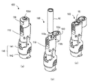
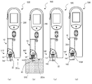
- FIG. 1 is a perspective view showing the appearance of a drug injection system including a cassette, a drug injection device and a charger.
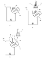
- 2 (a), 2 (b), and 2 (c) are perspective views illustrating the storage of the drug cartridge in the cassette.
- 3 (a), 3 (b), and 3 (c) are perspective views illustrating storage of the cassette in the drug injection device.
- 4 (a) and 4 (b) are perspective views illustrating a state in which injection is performed.
- FIG. 5 is a block diagram showing a configuration example of an electric circuit of a drug injection device.
- FIG. 6A is a diagram illustrating a state in which the drug injection device is set in the charger.
- FIG. 6B is a front view showing a state in which the drug injection device is set in the charger.
- FIG. 7A is a cross section parallel to the longitudinal direction of the drug cartridge.
- FIG. 7B is a cross section perpendicular to the longitudinal direction of the drug cartridge.
- FIG. 8A is a schematic plan view of the RF tag.
- FIG. 8B is a schematic plan view of another RF tag.
- FIG. 9A shows a schematic cross section of another drug cartridge.
- FIG. 9B shows a schematic cross section of another drug cartridge in line 9B-9B of FIG. 9A.
- 10 (a) and 10 (b) are schematic views illustrating the movement of the liquid component.
- FIG. 11 is an exploded perspective view of the hood of the cassette.
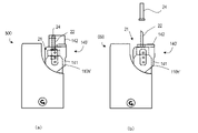
- 12 (a) and 12 (b) are diagrams illustrating the attachment of the needle unit to the cassette.
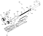
- FIG. 13 is an exploded perspective view of the drug injection device with the device housing removed.
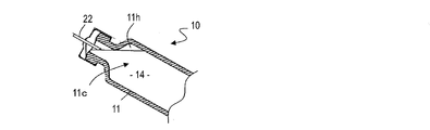
- FIG. 14 is a perspective view of a drug injection device showing the arrangement of the RF-ID antenna.
- FIG. 15 is an exploded perspective view of the piston drive mechanism.
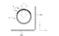
- FIG. 16A is a schematic diagram showing the positional relationship between the RF tag of the drug cartridge and the antenna in the drug injection device.
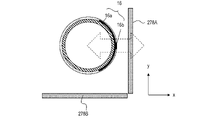
- FIG. 16B is a schematic diagram showing the positional relationship between the RF tag of the drug cartridge and the antenna in the drug injection device.
- FIG. 17 shows an example of driving information by PWM.
- FIG. 18A shows an example of the starting current generated when PWM control is not performed.
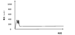
- FIG. 18B shows an example of the starting current by PWM control of this embodiment.
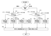
- FIG. 19A is a flowchart illustrating the operation of the drug injection device during the injection operation.
- FIG. 19B is a flowchart illustrating the operation of the drug injection device during the injection operation.
- FIG. 19C is a flowchart illustrating the reminding operation.
- FIG. 20 shows an example of the detection result of the touch sensor.
- FIG. 21 is a flowchart illustrating an injection operation of a drug injection device using a touch sensor.
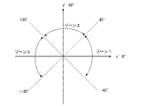
- FIG. 22 is a schematic diagram illustrating the directions of the three axes of the acceleration sensor.
- FIG. 23 is a schematic diagram illustrating a portion where air is difficult to escape when air is evacuated.
- FIG. 24 is a schematic diagram illustrating a posture suitable for bleeding air.
- FIG. 25 is a flowchart illustrating an air bleeding operation using an acceleration sensor.
- FIG. 25 is a flowchart illustrating an air bleeding operation using an acceleration sensor.
- FIG. 26 is a flowchart illustrating the mixing operation.
- FIG. 27 is a schematic diagram showing a zone used in the mixing operation.
- FIG. 28 is a schematic diagram illustrating an air bleeding operation.
- FIG. 29 is an exploded perspective view showing a part of the piston drive mechanism including the rotary encoder.
- FIG. 30 is a plan view of the encoder plate.
- FIG. 31 shows an example of a pulse signal.
- FIG. 32 is a block diagram showing an example of a failure determination device.
- FIG. 33 shows an example of an image displaying information stored in the RF tag.
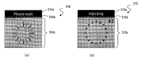
- 34 (a) to 34 (c) show an example of an image displayed during the air bleeding operation.
- 35 (a) and 35 (b) show an example of an image that encourages the operator to maintain the same state until the operation of the drug injection device is completed.
- FIG. 38A is a front view showing how the drug cartridge is loaded into the drug injection device.
- FIG. 38B is a front view showing how the drug cartridge is loaded into the drug injection device.
- FIG. 38C is a front view showing how the drug cartridge is loaded into the drug injection device.
- FIG. 39 is a diagram illustrating a state in which a needle unit is attached to a drug cartridge loaded in a drug injection device and a used injection needle is removed.
- FIG. 40 is a diagram illustrating a state in which a needle unit is attached to a drug cartridge loaded in a drug injection device and a used injection needle is removed.
- FIG. 41 is a diagram illustrating a state in which a needle unit is attached to a drug cartridge loaded in a drug injection device and a used injection needle is removed.
- FIG. 42 is a diagram illustrating a state in which an injection is performed using a drug injection device.
- the drug cartridge contains a plurality of doses of the drug
- a cold place such as a refrigerator
- the viscosity of the drug increases due to the low temperature.
- the drug cartridge or the drug injection device is taken out from a cold place and an injection is to be performed immediately, it is necessary to discharge the highly viscous drug from a small-diameter injection needle, which imposes a heavy load on the injection motor or the like. Such as this makes it difficult to properly drive and control the motor. Also, some patients may feel pain when infused with cold drugs.
- the waiting time until the injection becomes possible is substantially included in the time required for one injection, it is preferable for the patient to have a short waiting time. Also, the pain of injection is preferably small. On the other hand, it is preferable that the drug injection device is appropriately controlled according to the viscosity of the drug.
- the inventor of the present application has conceived a drug cartridge, a cassette, a drug injection device, and a drug injection system that can be appropriately managed and can reduce the burden on the operator.
- the drug cartridges, cassettes, drug infusion devices and drug infusion systems of the present disclosure are as follows.
- a drug cartridge provided with a first temperature sensor and an RF tag arranged on the side surface of the cylinder. The RF tag stores drug information including at least information indicating the type of the drug, and in response to an external command, information indicating at least the type of the drug and the temperature detected by the first temperature sensor.
- a cassette that stores a drug cartridge and is loaded into a drug injection device.
- a cassette columnar space capable of accommodating at least a part of a drug cartridge, an injection needle mounting portion located at the tip of the cassette columnar space and capable of attaching / detaching an injection needle, and a rear end of the cassette columnar space.
- a cassette cap that is supported so that the opening of the main body can be opened and closed in the vicinity of the rear end of the cassette main body.
- a needle concealment that is movably supported by the hood body and a needle concealment that is movably supported between the protruding position that protrudes from the hood body and the storage position that is at least partially housed in the hood body.
- a hood containing an urging member for urging in the direction of the protruding position, and a hood. Cassette with.
- a device housing having a space and a housing opening communicating with the housing space, A piston supported so as to be movable in the housing space, The motor that drives the piston and A motor driver that generates a drive signal to drive the motor, An antenna arranged adjacent to the housing space and A transmission / reception circuit for transmitting radio waves from the antenna and receiving radio waves received by the antenna, A display device that outputs information about the injection operation, The motor driver, the transmission / reception circuit, and a control device for controlling the display device are provided.
- the control device includes, in the transmission / reception circuit, information indicating the type of the drug in the drug cartridge, which is transmitted from the RF tag of the drug cartridge.
- Information and the first temperature information detected by the first temperature sensor are received via the antenna, the drive power of the motor based on the first temperature information is determined, and the determined drive power is output.
- a drug injection device that controls the motor driver.
- a device housing having a space and a housing opening communicating with the housing space, A piston supported so as to be movable in the housing space, The motor that drives the piston and A motor driver that generates a drive signal to drive the motor, An antenna arranged adjacent to the housing space and A transmission / reception circuit for transmitting radio waves from the antenna and receiving radio waves received by the antenna, Control information for controlling the motor for each of the plurality of agents, wherein the control information for each agent includes a set of control parameters for the motor for each of the plurality of temperature ranges, and the control information is stored.
- a display device that outputs information about the injection operation
- a control device that controls the motor driver, the transmission / reception circuit, the memory, and the display device.
- the RF tag stores drug information including at least information indicating the type of the drug.
- the control device With the drug cartridge loaded in the housing space, the control device The transmission / reception circuit is made to transmit a control signal via the antenna.
- the transmission / reception circuit receives the first temperature information and the drug information output from the first temperature sensor of the drug cartridge and the RF tag via the antenna. Based on the first temperature information and the drug information, one control parameter set is determined from the control information stored in the memory.
- the drug injection device according to item 9, wherein the motor is controlled using the determined control parameter set.
- the control parameter set of the motor in each temperature range includes an initial value and an increase width of the duty ratio of the drive signal due to the pulse width modulation.
- the control device controls the display device to display information indicating that injection is possible when the first temperature information is within the third temperature range of the third temperature or more and lower than the second temperature.
- the drug injection device according to item 15.
- the drug injection device according to item 15, further comprising a second temperature sensor provided in the device housing and outputting second temperature information indicating the temperature inside the device housing.
- the control device sequentially acquires the first temperature information at a predetermined time interval, and can inject based on the first temperature information and the second temperature information.
- Item 17 The drug injection device according to item 17, wherein the predicted time until the temperature is reached is sequentially calculated, and the display device is controlled so as to display the information indicating the calculated predicted time.
- the antenna includes a first portion and a second portion, each of which can independently receive an external signal.
- the drug injection device according to any one of items 8 to 18, wherein the first portion and the second portion are arranged adjacent to the housing space and orthogonally to each other.
- a user interface that accepts commands from the operator, including an injection button, With a surface charge transfer type touch sensor, Including
- the device housing has a skin contact surface that comes into contact with the operator's skin at the time of injection.
- the drug injection device according to any one of items 8 to 19, wherein the touch sensor is arranged on the skin contact surface.
- the control device is When the detection signal due to skin contact is received from the touch sensor and the signal due to the pressing of the injection button is received, the motor driver is controlled to perform the injection operation.
- the touch sensor detects skin separation during the injection operation,
- the drug injection device according to item 20, wherein the display device displays information indicating an abnormality.
- a sensor that has first, second, and third axes that are orthogonal to each other and detects acceleration along the axis or an angle around the axis, and one of the first, second, and third axes is that of the piston. Further equipped with sensors placed inside the housing to match the direction of movement, The drug injection device according to any one of items 8 to 21, wherein the control device causes the display device to display information regarding the posture of the drug injection device based on the detection signal of the sensor.
- a rotary encoder including an encoder plate attached to the rotary shaft of the motor and a pulse encoder.
- the encoder plate comprises one reference vane portion arranged on the circumference, each having a notch and a vane, and a plurality of normal vane portions.
- the lengths of the blades of the plurality of normal blade portions in the circumferential direction are equal to each other, and the lengths of the notches of the plurality of normal blade portions are equal to each other in the circumferential direction.
- the length of the blade of the reference blade portion in the circumferential direction and the length of the notch in the circumferential direction are the length of the blade of the plurality of normal blade portions in the circumferential direction and the length of the notch in the circumferential direction.
- the pulse encoder includes a light emitting element and a light receiving element arranged so that light emitted from the light emitting element is incident on the pulse encoder, and the reference blade portion of the encoder plate that rotates in accordance with the rotation of the motor and the reference blade portion.
- a pulse signal including a pulse corresponding to a blade of the reference blade portion and a pulse corresponding to the blade of the plurality of normal blade portions by a plurality of normal blade portions crossing an optical path between the light emitting element and the light receiving element.
- the length of the blade of the reference blade portion in the circumferential direction is larger than the length of the blade of the normal blade portion in the circumferential direction, and the length of the notch of the reference blade portion in the circumferential direction is the normal blade. 23.
- the control device calculates the number of blades of the reference blade portion and the blades of the plurality of normal blade portions per rotation of the encoder plate based on the pulse signal, and the calculation result is different from a predetermined value.
- the drug injection device according to any one of items 23 to 25, wherein the display device displays information indicating a failure.
- Item 22 The drug injection device according to item 22, wherein the control device reverses the direction of the information displayed on the display device based on the detection signal of the sensor.
- the control device is The drug injection device according to any one of items 8 to 27, which displays the drug information on the display device.
- the control device is The drug injection device according to any one of items 8 to 28, which displays a theme color corresponding to the type of the drug in common on a plurality of operation screens.
- the device housing includes a convex portion extending in the longitudinal direction, a skin contact surface located on the upper surface of the convex portion, a device concave portion adjacent to the skin contact surface, and a housing opening located at the bottom thereof, and the housing. It comprises a tip that covers the opening and includes an injection needle mounting portion with an inner space into which the tip of the drug cartridge is inserted.
- the housing space is adapted to accommodate at least a portion of the drug cartridge that is not contained in the cassette.
- the needle hiding which is located in the recess of the device and is rotatably attached to the housing of the device and is movably supported with respect to the hood body and the hood body, and the needle hiding in the direction of the protruding position. Further equipped with a hood containing urging members to urge The drug injection device according to item 8 or 9, wherein the hood is rotatable between a first position that covers the injection needle mounting portion and a second position that exposes the injection needle mounting portion.
- the drug injection device is With a secondary battery,
- the charging terminal provided on the device housing and Equipped with The device housing includes a tip including a convex portion extending in the longitudinal direction, a skin contact surface located on the upper surface of the convex portion, and a device concave portion adjacent to the skin contact surface, and the housing opening is the device.
- Located on the bottom of the recess In a state where the cassette is loaded in the housing space of the drug injection device, a part of the hood of the cassette is exposed to the outside in the recess of the device housing, and the other part of the hood is said.
- a charger including a power supply circuit for charging the secondary battery of the drug injection device and a charger housing containing the power supply circuit is further provided.
- the charger housing is provided at the bottom of the charger recess and the charger recess having a space into which the tip portion of the drug injection device can be inserted, and has a shape corresponding to the housing recess of the drug injection device.
- the charger housing has the tip of the drug injection device so that the charging terminal of the drug injection device is in contact with the supply terminal in a state where the cassette is not loaded in the drug injection device.
- FIG. 1 is a perspective view showing the appearance of a drug injection system 400 including a cassette 100, a drug injection device 200, and a charger 300.
- the cassette 100 houses the drug cartridge 10.
- 2 (a) to 2 (c) are perspective views illustrating the storage of the drug cartridge 10 in the cassette 100
- FIGS. 3 (a) to 3 (c) show the drug injection device 200 of the cassette 100.
- It is a perspective view explaining the storage in. 4 (a) and 4 (b) are perspective views illustrating a state in which injection is performed.
- FIG. 5 is a block diagram showing a configuration example of an electric circuit of the drug injection device 200. The outline of the drug infusion system will be described with reference to these figures.
- the drug infusion system of the present disclosure is typically used by the patient to inject himself. However, if the patient is young and it is not appropriate for the patient to handle the drug infusion system, a person other than the patient, such as a guardian, may handle the drug infusion system.
- the drug cartridge 10 stores, for example, a plurality of drugs to be injected into an operator such as a patient.
- the cassette 100 includes a cassette body 110, a cassette cap 130, and a hood 140.
- the cassette body 110 is located at a cassette columnar space 110c that can store at least a part of the drug cartridge 10, a tip 110a of the cassette columnar space 110c, an injection needle mounting portion 110h that allows the injection needle to be attached and detached, and the columnar space. It is located at the rear end 110b and has a main body opening 110e that can access the columnar space.
- the cassette cap 130 is supported so that the main body opening 110e can be opened and closed in the vicinity of the rear end 110b of the cassette main body 110.
- the hood 140 includes a hood body 141 and a needle hiding 142.
- the needle hiding 142 is movably supported by the hood body 141 between a protruding position protruding with respect to the hood body 141 and a storage position in which at least a part thereof is stored in the hood body 141.
- the loading of the drug cartridge 10 into the cassette 100 is completed by opening the cassette cap 130, inserting the drug cartridge 10 into the cassette columnar space 110c, and closing the cassette cap 130. If the medicine still remains in the medicine cartridge 10 after starting to use the new medicine cartridge 10, for example, the cassette 100 is stored in a case (not shown) with the medicine cartridge 10 loaded in the cassette 100, and a refrigerator or the like is used. Can be stored in a cold place.
- the drug cartridge 10 includes a first temperature sensor and an RF tag.
- the first temperature information detected by the first temperature sensor 15 is transmitted to the drug injection device 200 by the RF tag.
- the injection needle 21 can be attached to and detached from the injection needle mounting portion 110h of the cassette 100.
- the injection needle 21 is disposable and is handled separately from the cassette 100, for example, as a needle unit 20 except when in use.
- the needle unit 20 includes an injection needle 21, a needle cap 24 and a needle case 25.
- the injection needle 21 has a needle 22 and a connection portion 23 that supports the needle 22 and is detachably attached to the injection needle mounting portion 110h of the cassette 100.
- a male screw may be provided at the tip of the injection needle mounting portion 110h
- a female screw may be provided at the connection portion 23 of the injection needle 21.
- the needle cap 24 has a tubular shape that covers the needle 22, and the needle case 25 houses the injection needle 21 with the needle 22 covered by the needle cap 24.
- the drug cartridge 10, the cassette 100, and the drug injection device 200 each have a longitudinal direction L.
- the end to which the injection needle 21 is attached is referred to as a tip, a tip portion, or a tip portion.
- the ends of the drug cartridge 10, the cassette 100, and the drug injection device 200 in the longitudinal direction opposite to the front end are referred to as a rear end, a rear end portion, or a rear end portion.
- the drug injection device 200 includes a device housing 201.
- the device housing 201 has a tubular shape having a thickness that is easy for an operator to grasp with one hand, for example.
- the device housing 201 has an oval shape in a cross section perpendicular to the longitudinal direction, and has a shape that is easy for the operator to hold.
- the shape of the device housing 201 is not limited to this, and may have a cylindrical shape or a square cylinder shape.
- the tip portion 201a which is one of both ends in the longitudinal direction of the device housing 201, has a convex portion 201t extending in the longitudinal direction and a device recess 201r.
- the device concave portion 201r is adjacent to the convex portion 201t, and the convex portion 201t and the device concave portion 201r are provided by providing a notch in the tubular shape for cutting out a part of the end face and a part of the side surface in the tubular shape of the device housing 201. And are formed.
- the upper surface of the convex portion 201t is referred to as a skin contact surface 201e.
- a housing opening 201d into which the cassette 100 can be inserted is located on the bottom surface of the device recess 201r.
- the drug injection device 200 has a housing space 201c capable of accommodating at least a part of the cassette 100 in the device housing 201, and the housing space 201c is connected to the housing opening 201d.
- the drug injection device 200 includes a power button 255, a selection button 256, a decision button 257, an injection button 258, a discharge lever 209, and a display device 259 on the surface of the device housing 201.
- the surface on which these buttons and the display device 259 are located is referred to as a front surface.
- the power button 255, the selection button 256, the enter button 257, and the injection button 258 are examples of a user interface that accepts commands from the operator. Part or all of the user interface may be a touch panel provided on the display device 259.
- a charging terminal 201g is arranged at the tip portion 201a of the device housing 201, which will be described later.
- the power button 255 When using the drug injection system 400, when the power button 255 is pressed to activate the drug injection device 200, the operation procedure of the drug injection device 200 is displayed on the display device 259, and the drug in the drug cartridge 10 in the loaded cassette 100 is charged. Information, injection history, etc. are displayed.
- the cassette 100 to which the needle unit 20 is mounted is loaded into the drug injection device 200 from the housing opening 201d, and the needle case 25 and the needle cap 24 are removed. .. In this state, the needle 22 is located in the space surrounded by the needle hiding 142, and the tip of the needle 22 does not protrude from the needle hiding 142.
- the drug injection device 200 of the present embodiment is a semi-automatic type, and the needle sticking and needle removal are performed manually, that is, by the operator.
- FIGS. 4A and 4B when the drug injection device 200 is pressed against the skin from the state where the drug injection device 200 is held so that the tip of the needle concealment 142 comes into contact with the skin, the needle is pressed. The hidden 142 retracts into the hood body 141. Along with this, the tip of the needle 22 comes into contact with the skin, and the injection needle 22 is inserted into the skin at a predetermined depth. Subsequently, when the injection button 258 is pressed, a predetermined amount of the drug is injected from the drug cartridge 10.
- the injection needle 21 is pulled out from the skin. After that, the discharge lever 209 is operated to discharge the cassette 100 from the drug injection device 200.
- the drug injection device 200 includes a control unit 251 including a computer such as a CPU, a secondary battery 253 as a power source, and a charging unit 252 including a charging circuit for charging the secondary battery 253.
- a memory 254 for storing computer programs, data, and the like, and a clock 261 are provided.
- the control unit 251 and the memory 254 configure the control device 280, and the control unit 251 reads the program stored in the memory 254 and controls each component shown in FIG. 5 according to the procedure of the computer program.
- the procedure of the computer program is shown by the flow chart of the description and the attached drawing described later.
- the drug injection device 200 may further include a buzzer 260 that notifies the operator by sound.
- the drug injection device 200 further includes a motor driver 263, a motor 264, and a rotary encoder 265.
- the motor driver 263, the motor 264, and the rotary encoder 265 form a part of the piston drive mechanism as described later.
- the drug injection device 200 includes various detectors for detecting the state of each part of the drug injection device 200.
- the drug injection device 200 includes a piston origin detector 271, a cassette loading detector 272, a discharge lever detector 274, a touch sensor 275 and an acceleration sensor 276.
- the drug injection device 200 may further include a second temperature sensor 273.
- the drug injection device 200 includes an RF-ID reader 277.
- the drug injection device 200 may further include an RF-ID writer.
- the RF-ID reader 277 reads the drug information including the first temperature information of the first temperature sensor 15 transmitted from the RF tag 16 of the drug cartridge 10 and the information indicating the type of the drug stored in the memory of the RF tag 16. ..
- the read information is input to the control unit 251 and uses the acquired first temperature information to control the motor and control the operation of the drug injection device 200.
- the drug injection device 200 may further include a communication unit 262.
- the communication unit 262 transmits / receives information to / from the outside by, for example, infrared communication, wireless communication, or the like.
- the communication unit 262 may be a transmitter / receiver that uses a short-range wireless communication standard such as BLE (Bluetooth Low Energy, Bluetooth is a registered trademark).
- BLE Bluetooth Low Energy, Bluetooth is a registered trademark.
- the time when the operator used the drug injection device 200, the type of the drug, the injection amount, etc. are stored in the memory 254 at the time of use, and these information are stored in the memory 254 at a predetermined timing using the communication unit 262, such as a smartphone or a tablet.
- a portable device such as a terminal or a dedicated device for managing the drug injection device 200.
- the above-mentioned information may be transmitted from a mobile device to a server such as a hospital or a drug maker via a mobile phone line or an Internet line.
- the charger 300 includes a charging housing 301 and a power supply circuit arranged in the charging housing 301.
- the charging housing 301 has a charger recess 301r having a space into which the tip portion 201a of the drug injection device 200 can be inserted.
- the charging housing 301 is provided at the bottom of the charger recess 301r, has a step 301s having a shape corresponding to the device recess 201r provided at the tip 201a of the drug injection device 200, and is inside the charger recess 301r. It includes a space 301u adjacent to the step 301s and a supply terminal 301e located in the charger recess 301r and connected to the charging circuit. On the side surface of the charger recess 301r, a plurality of ribs 301d extending in the depth direction of the charger recess 301r are provided.
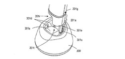
- FIG. 6A is a diagram illustrating a state in which the drug injection device 200 is set in the charger 300
- FIG. 6B is a front view showing a state in which the drug injection device 200 is set in the charger 300.
- the tip portion 201a of the drug injection device 200 is housed in the charger recess 301r so that the charging terminal 201g of the drug injection device 200 is in contact with the supply terminal 301e.
- the side surface of the tip portion 201a of the drug injection device 200 is in contact with the rib 301d of the charger 300. Therefore, a space is formed between the side surface of the charger recess 301r and the side surface of the tip portion 201a of the drug injection device 200. This space makes it possible to release the heat of the secondary battery generated by charging to the outside of the charger recess 301r.
- the charger 300 can hold the drug injection device 200 in a state where the drug injection device 200 is upright.
- the charger 300 functions as a storage place for the drug injection device 200 when not in use, and when the drug injection device 200 is stored sideways or the drug injection device 200 is stored and charged in the case. In comparison, it is possible to store the drug injection device 200 in a conspicuous state without taking up a lot of space.
- the cassette 100 when the cassette 100 is loaded in the drug injection device 200, a part of the cassette 100 protrudes into the device recess 201r. Therefore, even if the tip portion 201a of the drug injection device 200 is to be inserted into the charger concave portion 301r of the charger 300, the cassette 100 interferes with the step 301s of the charger concave portion 301r, so that the convex portion 201t is lateral to the step 301s. It cannot be inserted into the space 301u, and the entire tip portion 201a cannot be inserted into the charger recess 301r. Therefore, the tip portion 201a of the drug injection device 200 cannot be housed in the charger recess 301r, and the drug injection device 200 cannot be set in the charger 300.
- the drug injection device 200 cannot be loaded into the charger 300 with the cassette 100 inserted. Therefore, the cassette 100 is always removed during charging, and it is possible to prevent the chemicals in the cassette 100 from deteriorating due to heat generated by the chemical injection device 200 during charging.
- the drug cartridge 10 since the drug cartridge 10 includes the first temperature sensor 15, the temperature of the drug stored in the drug cartridge 10 can be measured. Using this information, it is possible to estimate the viscosity of the drug, drive the motor with a driving force according to the viscosity, determine whether the temperature is suitable for injection, and control the operation of the drug injection device 200.
- the drug cartridge 10, the cassette 100, and the drug injection device 200 will be described in detail.
- FIG. 7A is a cross section parallel to the longitudinal direction of the drug cartridge 10
- FIG. 7B is a cross section perpendicular to the longitudinal direction of the drug cartridge 10.
- the drug cartridge 10 includes a cylinder 11, a cylinder cap 12, a gasket 13, a drug 14, and an RF tag 16.
- the cylinder 11 has a first end 11a and a second end 11b separated in the longitudinal direction, and a cylinder columnar space 11c located between the first end 11a and the second end 11b.
- the needle 22 of the injection needle 21 can be inserted and removed from the first end 11a.
- the outer shape of the cylinder 11 is narrowed on the first end 11a side so that the cross section perpendicular to the longitudinal direction of the cylinder columnar space 11c becomes smaller on the first end 11a side, and the first end 11a is made of rubber.
- the opening on the first end 11a side of the cylinder columnar space 11c is sealed with the cylinder cap 12 made of the above.
- the cylinder 11 has a cylinder opening 11d connected to the cylinder columnar space 11c at the second end 11b.
- the gasket 13 is inserted into the cylinder columnar space 11c from the cylinder opening 11d and is supported on the inner wall of the cylinder 11 so as to be movable in the longitudinal direction.
- the first end 11a and the second end 11b side of the cylinder columnar space 11c are closed by the cylinder cap 12 and the gasket 13, and the drug 14 is sealed in the closed cylinder columnar space 11c.
- the drug 14 contains at least the first component of the liquid and is liquid at room temperature.
- the RF tag 16 is a device that stores identification information of an object to which the tag is attached and wirelessly transmits the identification information.
- the RF tag 16 stores drug information including at least information indicating the type of the drug in the cylinder columnar space 11c, and in response to an external command, information indicating the type of the drug and a second. 1
- the first temperature information indicating the temperature detected by the temperature sensor is wirelessly transmitted to the outside.
- the RF tag 16 may be an active type or a passive type.
- the RF tag 16 is a passive type and is an RF tag with a temperature sensor.
- the RF tag 16 includes an antenna 16a and an IC 16b.
- the antenna 16a transmits and receives electromagnetic waves in a long wave, a short wave, or a microwave band.
- the IC 16b includes a transmission unit, a reception unit, a storage unit, and a power supply rectification unit.
- the IC 16b of the present embodiment further includes a first temperature sensor.
- the RF tag 16' may include an antenna 16a and an IC 16c that does not include a temperature sensor.
- the drug cartridge 10 further includes a first temperature sensor 15 electrically connected to the IC 16c.
- the RF tag 16 or the RF tag 16'and the first temperature sensor 15 are supported by, for example, affixing to a label 17 or laminating.
- the label 17 is affixed to the outer surface of the cylinder 11.
- the name of the drug 14 or the like may be written on the outside of the attached label 17.
- the drug information described later may be described in characters, pictograms, or the like.
- the first temperature sensor detects the ambient temperature of the second temperature sensor.
- the temperature of the cylinder 11 is directly detected.
- the temperature of the cylinder 11 is the same as the temperature of the drug in the cylinder columnar space 11c. Therefore, it can be said that the first temperature sensor detects the temperature of the drug in the drug cartridge 10.
- the storage unit stores drug information regarding the drug in the cylinder columnar space 11c.
- the drug information includes at least information indicating the type of drug.
- the drug information further includes information indicating the expiration date of the drug, information indicating the initial amount of the drug in an unused state, information on manufacturing such as a manufacturing rod of the drug, unique identification information of the drug cartridge 10, and viscosity of the drug. Information and the like may be stored.
- the antenna 16a receives a signal transmitted from the drug injection device 200 described later, an electromotive force due to resonance is generated, and the power supply rectifying unit of the IC 16b rectifies the electromotive force to drive the RF tag 16. Power is generated.
- the IC 16b is activated, the drug information stored in the storage unit and the first temperature information indicating the temperature detected by the first temperature sensor are read out, and the information read by the transmission unit is converted into electromagnetic waves to convert the antenna into an electromagnetic wave. It is transmitted from 16a to the outside. The transmitted information is received by the drug injecting device and used for controlling the drug injecting device as described later.
- the drug cartridge 10 is provided with the first temperature sensor, it is possible to detect the temperature of the drug in response to a request from the drug injection device 200. Therefore, when using a drug cartridge stored at a low temperature for injection, the temperature of the drug is used to determine whether or not the temperature is suitable for injection, and the viscosity according to the temperature of the drug is estimated and appropriate. It is possible to realize a drug injection device capable of injecting a drug with a sufficient driving force.
- the drug cartridge 10 contains only a liquid component, but the drug cartridge of the present disclosure may contain a solid component and a liquid component.
- FIG. 9A shows a schematic cross section of a drug cartridge 10'containing a drug in which a liquid component and a solid component are separately and retained in an unused state
- FIG. 9B shows a line cross section taken along the line 9B-9B of FIG. 9A.
- the drug cartridge 10' includes a cylinder 11', a first gasket 13A, a second gasket 13B, a liquid component 14A containing the first component of the drug 14, and a solid component 14B containing the second component.
- the liquid component 14A is liquid at room temperature
- the solid component 14B is solid at room temperature.
- the solid component 14B is in contact with and supported by, for example, the inner surface of the cylinder 11'.
- the label 17 and the RF tag 16 are arranged on the side surface of the cylinder 11'.
- the cylinder 11' has a cylinder columnar space 11c, and the cylinder columnar space 11c has a first region 11c1 located on the first end 11a side, a second region 11c2 located on the second end 11b side, and a first region.
- the third region 11c3 sandwiched between the 11c1 and the second region 11c2 is included.
- the protrusion 11t extends in the longitudinal direction and defines a bypass space 11e arranged adjacent to the cylinder columnar space 11c in a cross section perpendicular to the longitudinal direction.
- the longitudinal length Lb of the bypass space 11e is longer than the longitudinal length Lg in contact with the inner surface of the cylinder 11'of the second gasket 13B (Lb> Lg).
- the second gasket 13B In the initial state where the drug cartridge 10'is unused, at least a part of the second gasket 13B is located in the second region 11c2.
- the first gasket 13A is located on the second end 11b side of the second region 11c2 in the cylinder columnar space 11c.
- the liquid component 14A of the drug is located in the second region 11c2 and is sandwiched between the first gasket 13A and the second gasket 13B.
- the solid component 14B is located in the first region 11c1 of the cylinder columnar space 11c.
- FIG. 10 (a) and 10 (b) are schematic views illustrating the movement of the liquid component 14A during dissolution of the solid component 14B.
- the piston 210 of the drug injection device 200 advances the first gasket 13A.
- the rear end of the second gasket 13B is in the second region 11c2
- the space between the first gasket 13A and the second gasket 13B is sealed. Therefore, as the first gasket 13A advances, the second gasket 13B And the liquid component 14A advances together.
- the longitudinal length Lg of the second gasket 13B is larger than the longitudinal length Lb of the bypass space 11e.
- the first region 11c1 located in front of the second gasket 13B and the second region 11c2 located behind the second gasket 13B are connected by the bypass space 11e.
- the liquid component 14A flows into the first region 11c1 through the bypass space 11e.
- the second gasket 13B does not move, and only the liquid component 14A moves to the first region 11c1.
- the liquid component 14A comes into contact with the solid component 14B, and the solid component 14B dissolves in the liquid component 14A.
- the solid component 14B in contact with the liquid component 14A is dissolved in the liquid component 14A by shaking the entire drug cartridge 10'by the operation of the operator.
- the drug information can be stored in the storage unit of the RF tag 16. Therefore, by transmitting the stored drug information and the first temperature information of the drug to the drug injection device 200, the drug injection device 200 can be controlled by a procedure different from that of the drug cartridge containing only the liquid component, or the drug can be controlled. It is possible to perform the melting operation according to the temperature.
- the cassette 100 includes a cassette body 110, a cassette cap 130, and a hood 140.
- the operator can more safely handle the cassette 100 or the drug injection device 200 to which the cassette 100 is attached in a state where the injection needle 21 is attached. ..
- FIG. 11 is an exploded perspective view of the hood 140 of the cassette 100.
- the hood 140 includes a hood body 141, a needle hiding 142, and an urging member 143.
- the needle concealment 142 has a substantially U-shape in a cross section perpendicular to the longitudinal direction.
- the hood body 141 also has a portion having a substantially U-shape in a cross section perpendicular to the longitudinal direction.
- the needle hiding 142 is supported so as to be movable in the longitudinal direction with respect to the hood body 141.
- the urging member 143 urges the needle concealment 142 in a direction protruding from the hood body 141.
- the urging member 143 is a spring, but it may be another elastic member.
- the needle concealment 142 includes a transparent first portion 142c and a translucent second portion 142d. More specifically, the first portion 142c is a region extending in the longitudinal direction, for example, located at the bottom of a substantially U-shaped cross section in a cross section perpendicular to the longitudinal direction. The second portion 142d is located so as to sandwich the first portion 142c.
- the hood body 141 is rotatably supported by the cassette body 110 at the rear end 141b in the longitudinal direction. As a result, the hood 140 can rotate between the first position that covers the injection needle mounting portion and the second position that exposes the injection needle mounting portion. Further, the hood body 141 is connected to the rear end 141b and has an arm portion 141c extending in the longitudinal direction opposite to the hood body 141.
- the hood body 141 is made of, for example, an opaque material. Transparent and opaque may be colorless or colored.
- FIG. 12 (a) and 12 (b) are diagrams illustrating the attachment of the needle unit 20 to the cassette 100.
- the drug cartridge 10 is inserted in the cassette 100 in advance.
- FIG. 12A first, the hood 140 is rotated to the second position. In this state, the hood 140 does not cover the injection needle mounting portion 110h of the cassette 100, and the injection needle mounting portion 110h is exposed. In particular, the hood 140 is located below (rear end side) the injection needle mounting portion 110h. Therefore, for example, when the operator attaches the needle unit 20 to the injection needle mounting portion 110h, the hand does not hit the hood 140 and the attachment is easy.
- FIG. 12B when the attachment of the needle unit 20 is completed, the hood 140 is rotated to the first position. As a result, the portion of the needle unit 20 other than the tip portion 201a is covered by the hood 140 from three directions.
- FIG. 3A in this state, the cassette 100 is inserted into the housing space 201c from the housing opening 201d of the drug injection device 200.
- FIG. 3B shows a state in which loading of the cassette 100 is completed.
- a part of the hood 140 is exposed in the device recess 201r of the tip portion 201a, and a part is located in the housing opening 201d.
- at least the arm portion 141c of the hood body 141 is located in the housing opening 201d. Therefore, in this state, for example, the operator rotates the hood 140 to the second position, that is, even if the hood 140 is opened so that the needle unit 20 is exposed, the arm portion 141c is in the housing space 201c.
- the hood 140 cannot be rotated because it comes into contact with the internal housing of the drug injection device 200.
- a part of the hood body 141 surrounds the device recess 201r at the tip portion 201a. Therefore, at the time of administration, the drug injection device 200 can be stably pressed and held against the skin.
- the needle cap 24 and the needle case 25 are removed from the needle unit 20, and the injection needle 21 is exposed.
- the tip of the exposed injection needle 21 is lower than the tip of the needle hiding 142.
- the translucent second portion 142d of the needle concealment 142 faces the same direction as the front surface on which the display device 259 of the drug injection device 200 is arranged. Therefore, when the operator performs an injection, the operator visually recognizes the injection needle 21 through the second portion 142d of the needle concealment 142. Since the second portion 142d is translucent, the operator can recognize that the shape of the injection needle 21 is obscured, but that the needle 22 is attached. Therefore, the operator can confirm that the injection needle 21 is correctly attached, and can suppress the occurrence of fear by not clearly recognizing the needle 22.
- the first part 142c is transparent to the needle concealment 142, and the first part faces the same direction as the side surface of the drug injection device 200. Therefore, the operator can clearly see the injection needle 21 via the first portion 142c. As will be described later, for example, when performing the air bleeding operation in the drug cartridge 10, it can be confirmed through the first portion 142c that the drug seeps out from the tip of the injection needle 21, and it is determined that the air bleeding is completed. It is possible to do.
- the needle concealment 142 retracts and is housed in the hood body 141, so that the injection needle 21 is relatively needled. It protrudes from the tip of the hidden 142. As a result, the injection needle 21 is inserted into the skin until the skin contact surface 201e of the convex portion 201t of the drug injection device 200 comes into contact with the skin.
- the needle concealment 142 protrudes toward the tip side by the urging member 143 and covers the injection needle 21 again.
- the cassette 100 for storing the drug cartridge 10 has been described above, the cassette of the present embodiment can be similarly configured even when the above-mentioned drug cartridge 10'is stored.
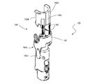
- FIG. 13 is an exploded perspective view of the drug injection device 200 with the device housing 201 removed
- FIG. 14 is a perspective view of the drug injection device 200 showing the arrangement of the RF-ID antenna.
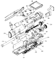
- FIG. 15 is an exploded perspective view of the piston drive mechanism 220 of the drug injection device 200.
- the drug injection device 200 includes a piston 210 and a piston drive mechanism 220 in addition to the above-mentioned device housing 201 and control device 280.
- the drug injection device 200 further includes an internal housing 202, a main board 290, a first sub board 291 and a second sub board 292.
- the internal housing 202 supports the piston drive mechanism 220.
- a control device 280 and a motor driver 263 are formed on the main board 290.
- An acceleration sensor 276 is also arranged on the main board 290.
- the RF-ID reader 277 includes an antenna 278 and a transmission / reception circuit 279.
- the transmission / reception circuit 279 is formed on the main board 290, for example.
- a selection button 256, a decision button 257, an injection button 258, and a second temperature sensor 273 are arranged on the second subboard 292. It is preferable that the second temperature sensor 273 is arranged at a position that is not easily affected by the heat generated by various parts in the apparatus housing 201 during operation.
- the RF-ID reader 277 receives the first temperature information transmitted from the drug cartridge 10 and the drug stored in the memory of the RF tag 16. Read drug information, including information indicating the type of. Based on this information, the drug injection device 200 injects the drug in the drug cartridge 10 into the operator by moving the piston 210.
- the structures of the RF-ID reader 277 and the piston drive mechanism 220 of the drug injection device 200 will be mainly described.
- the RF-ID reader 277 includes an antenna 278 and a transmission / reception circuit 279.
- the antenna 278 includes a first portion 278A and a second portion 278B, each of which can independently receive an external signal.
- the first portion 278A and the second portion 278B of the antenna 278 are arranged adjacent to the housing space 201c. It is preferable that the first portion 278A and the second portion 278B each include a substantially planar radiation conductor and are arranged orthogonal to each other.
- FIGS. 16A and 16B schematically show the positional relationship between the RF tag 16 and the first portion 278A and the second portion 278B of the antenna 278 in a state where the cassette 100 into which the drug cartridge 10 is inserted is loaded in the drug injection device 200. Shown. In FIGS. 16A and 16B, the cassette 100 is not shown.
- the drug cartridge 10 has a cylindrical shape, and the outer shape of the cross section perpendicular to the longitudinal direction has a substantially circular shape. Therefore, it can be inserted in any direction (angle) around the axis with respect to the cassette columnar space 110c of the cassette 100. Therefore, when the cassette 100 is loaded into the drug injection device 200, the flat plate-shaped RF tag 16 can be oriented in any direction.
- the antenna 16a of the RF tag 16 has a substantially planar shape and has directivity. Specifically, the antenna 16a transmits an electromagnetic wave having a large electric field strength distribution in a direction perpendicular to the planar shape. Therefore, if the antenna 278 of the RF-ID reader 277 has high reception sensitivity in only one direction, the direction in which the reception sensitivity of the antenna 278 is high and the electric field of the electromagnetic wave transmitted from the antenna 16a of the RF tag 16 There is a possibility that the electromagnetic wave transmitted from the RF tag 16 cannot be correctly received because the direction in which the intensity is strong is orthogonal or close to orthogonal.
- the antenna 278 since the first portion 278A and the second portion 278B of the antenna 278 are arranged orthogonal to each other, the antenna 278 has high sensitivity in two orthogonal directions. Therefore, for example, as shown in FIG. 16A, when the antenna 16a of the RF tag 16 spreads substantially perpendicular to the y direction, the antenna 278 has a strong sensitivity in the first portion 278A, and the antenna 16a of the RF tag 16 has a strong sensitivity. Although it is not possible to receive the electromagnetic wave from the RF tag 16, the second portion 278B can receive the electromagnetic wave from the antenna 16a of the RF tag 16 with sufficient sensitivity. Further, as shown in FIG.
- the antenna 278 when the antenna 16a of the RF tag 16 spreads substantially perpendicular to the x direction, the antenna 278 receives the electromagnetic wave from the antenna 16a of the RF tag 16 with high sensitivity in the second portion 278B. Although it cannot be received, the first portion 278A can receive the electromagnetic wave from the antenna 16a of the RF tag 16 with sufficient sensitivity. Even when the antenna 16a of the RF tag 16 is oriented in a direction other than the directions shown in FIGS. 16A and 16B, the first portion 278A or the second portion 278B of the antenna 278 allows the antenna 16a of the RF tag 16 to have sufficiently high sensitivity. Can receive electromagnetic waves. Therefore, according to the drug injection device 200 of the present embodiment, the drug information including the first temperature information and the information indicating the type of the drug stored in the memory of the RF tag 16 more reliably from the drug cartridge 10 in the cassette 100. Is possible to read.
- the information from the RF tag 16 attached to the drug cartridge 10 is read by the RF-ID reader 277, for example, by the following procedure.
- a start-up signal is generated from the transmission / reception circuit 279 of the RF-ID reader 277, and the first part 278A of the antenna 278 and / or Electromagnetic waves are transmitted from the second part 278B.
- the antenna 16a of the RF tag 16 receives the electromagnetic wave
- the antenna 16a receives the electromagnetic wave
- an electromotive force is generated by resonance.
- the generated electromotive force activates the IC 16b to read out the information even stored in the storage unit and convert it into a signal.
- the temperature detected by the first temperature sensor is signalized.
- the generated signal is sent from the IC 16b to the antenna 16a, and an electromagnetic wave is transmitted from the antenna 16a.
- the RF-ID reader 277 receives the electromagnetic wave from the RF tag 16 by the first portion 278A or the second portion 278B of the antenna 278, and is converted into a signal by the transmission / reception circuit 279.
- drug information including the first temperature information and information indicating the type of the drug stored in the memory of the RF tag 16 can be obtained. This information is transmitted to the control device 280.
- the piston 210 includes a tip 211 and a body 212 connected to the tip 211.
- the tip portion 211 is located on the first end 210a side.
- the tip portion 211 has an I-cut shape in which a cylinder is cut by two parallel two planes along an axis.
- the tip portion 211 has a shape corresponding to the cap opening 130d provided in the cassette cap 130 of the cassette 100.
- the piston 210 includes a drive convex portion 213 located on the side surface of the main body 212.
- the drive convex portion 213 regulates rotation according to the shape of the guide 231 by engaging with the guide 231 provided in the piston drive mechanism 220 as described later.
- the drive convex portion 213 is a rib provided on the side surface of the piston 210, and the rib is a ridge-shaped convex portion extending parallel to the axis of the piston 210.
- the piston 210 has two drive protrusions 213 arranged on the second end 210b side of the side surface of the main body.
- the main body 212 of the piston 210 is provided with a female screw 214 located inside a hole 210h extending along the axis of the piston 210.
- the piston drive mechanism 220 includes a motor 264, a gearbox 221, a drive gear 222, a drive rod 235, and a piston guide 230.
- the motor 264, the gearbox 221 and the drive gear 222 and the piston guide 230 are supported by the internal housing 202.
- the motor 264 rotates forward or reverse based on the control of the control device 280.
- forward rotation means rotation in the direction in which the piston 210 is advanced
- reverse rotation means rotation in the direction in which the piston 210 is retracted.
- a rotary encoder 265 is attached to the rotation shaft of the motor 264 as a rotation amount detector, and the rotary encoder 265 detects the rotation amount (rotation number) of the motor 264.
- the rotary encoder 265 includes an encoder plate 266 and a pulse encoder 267 including a light emitting element and a light receiving element. The rotary encoder 265 will be described in detail below.
- the gearbox 221 contains at least one gear attached to the rotating shaft of the motor 264.
- the gearbox 221 may include two or more gears to reduce the rotational speed of the motor 264.
- the drive gear 222 meshes with the gear of the gearbox 221 and is rotatably supported by the internal housing 202 by the bearing 223.
- a hole is provided in the shaft of the drive gear 222, and one end of the drive rod 235 is inserted and fitted.
- the drive rod 235 has a rod shape, and a male screw 236 is formed on the side surface.
- the male screw 236 has a thread height, a shape, a screw pitch, and the like so as to mesh with the female screw 214 provided on the piston 210.
- the piston guide 230 has a hole 230h into which the piston 210 is inserted.
- a guide 231 is provided on the inner surface of the hole 230h. The guide 231 engages with the drive protrusion 213 of the piston 210 and guides the piston 210 forward or backward without rotating it about an axis.
- the guide 231 is a straight groove extending parallel to the axis of the hole 230h, and a rib which is a drive convex portion 213 provided on the side surface of the piston 210 is inserted.
- the piston guide 230 includes two guides 231 corresponding to the two drive protrusions 213 of the piston 210.
- the drive gear 222 rotates via the gearbox 221 and the drive rod 235 rotates.
- the female screw 214 of the piston 210 that meshes with the male screw 236 of the drive rod 235 receives a rotational force around the axis. Since the drive protrusion 213 of the piston 210 is inserted into the groove of the guide 231, the guide 231 restricts the rotation of the piston 210 around the axis, and the piston 210 advances without rotating according to the rotation of the drive rod 235. ..
- the viscosity of the liquid drug 14 changes with temperature. Generally, the higher the temperature of the drug, the lower the viscosity. In addition, the viscosity varies depending on the type of drug. Further, even if the same drug is stored in the drug cartridge, the load required to move the gasket 13 may differ if the diameter of the cylinder 11 is different due to the difference in the capacity of the cylinder 11. In the conventional drug injection device, the most viscous drug and drug cartridge among the corresponding drugs and drug cartridges can be performed so that smooth injection operation can be performed regardless of the type of drug and the capacity of the drug cartridge 10. It provided the motor with a sufficiently high drive voltage to handle the heaviest drug cartridge.
- the problem that a cold drug may be injecting may cause pain, and the operator has dealt with the problem by leaving the drug cartridge indoors for a certain period of time before injecting. Time management such as leaving it for a certain period of time is troublesome for the operator, and the temperature inside the room when injecting is different depending on the season, place, etc., so even if it is left for the same time, the drug cartridge is the same. It does not always reach the temperature.
- the drug information including the information indicating the type of the drug in the drug cartridge transmitted from the RF tag 16 of the drug cartridge and the first temperature information detected by the first temperature sensor are stored in the RF-ID reader 277.
- the motor driver is controlled so as to determine the drive power of the motor based on the first temperature information and output the determined drive power. Further, when the temperature indicated by the first temperature information is in a certain temperature range, the injection operation is not started by determining that the temperature is not suitable for injection and not driving the motor 264.
- the memory 254 stores control information for controlling the motor 264 for each of a plurality of agents.
- the control information for each drug contains a set of motor control parameters for each of the multiple temperature ranges.
- Table 1 shows an example of a set of motor control parameters stored in the memory 254.
- Drug A and Drug B are shown as examples of the plurality of drugs.
- the viscosity of the drug B is higher than the viscosity of the drug A.
- temperature ranges of less than 0 ° C., 0 ° C. or higher and lower than 10 ° C., 10 ° C. or higher and lower than 20 ° C., 20 ° C. or higher and lower than 38 ° C., and 38 ° C. or higher are shown.
- 0 ° C., 38 ° C. and 10 ° C. are examples of the first temperature, the second temperature and the third temperature, respectively.
- the memory 254 may further comprise a set of motor control parameters in the absence of such a drug cartridge.
- the drug may be frozen. Further, when the first temperature information is 38 ° C. or higher, there is a possibility that the drug has been altered by being stored at a high temperature. If the first temperature information is in these two temperature ranges, it is not preferable to make an injection. Therefore, the driving information C is assigned regardless of whether the type of the drug in the drug information is A or B.
- the drive information C may be, for example, information that the motor 264 is not driven.
- injection cannot be performed in any temperature range, so that the drive information C is assigned in all temperature ranges. In the temperature range of 0 ° C. or higher and lower than 10 ° C., 10 ° C. or higher and lower than 20 ° C., and 20 ° C. or higher and lower than 38 ° C.
- Each control parameter set is assigned.
- Table 2 shows a specific example of the control parameter set of the drive information A1, A2, A3 and the drive information B1, B2, B3.
- the drive power of the motor may be adjusted, for example, the applied voltage may be adjusted, or may be adjusted by another method.
- the drive power is adjusted by PWM (Pulse Width Modulation) to control the motor.
- FIG. 17 shows an example of a drive signal by PWM and a rotation speed of a motor rotated by the drive signal.
- the drive information that defines the drive signal by PWM includes, for example, a duty ratio initial value, a duty ratio increase width, an increase period, an increase maximum waiting time, and a target arrival duty ratio.
- the viscosity of drug B is higher than the viscosity of drug A. Therefore, when comparing each temperature range, the initial value of the duty ratio initial value is larger for the drug B than for the drug A. This is because a larger driving force is required to drive a highly viscous drug.
- the increase period and the maximum increase waiting time are shorter for the drug B than for the drug A, and the target duty ratio is larger for the drug B than the drug A in each temperature range.
- the value of the parameter becomes smaller as the temperature range becomes higher. That is, the higher the lower limit of each temperature range, the smaller the duty ratio initial value, duty ratio increase width, increase period, increase maximum waiting time, and target arrival duty ratio. This is because the higher the temperature of the drug, the lower the viscosity and the smaller the power generated by driving.
- the control device 280 reads the drive information A2 from the memory 254 and uses the parameters included in the drive information A2 to drive the motor driver 263. Drive.
- the duty ratio gradually increases, so that the control device 280 gradually increases the current flowing through the motor.
- the motor driver is made to generate a drive signal so as to increase the duty cycle.
- the duty ratio reaches the target duty ratio, the drive is continued at the target duty ratio.
- the peak value of the starting (starting) current current overrun is performed by performing PWM control with the initial value of the duty ratio according to the viscosity of the drug and the stepwise increase in the duty ratio.
- the shoot) can be made smaller.
- FIG. 18A shows a starting current generated when PWM control is not performed
- FIG. 18B shows an example of a starting current generated by PWM control according to the present embodiment.
- a peak current of about 800 mA flows at the maximum.
- the peak current can be suppressed to about 400 mA.
- the initial value of the duty ratio according to the viscosity of the drug contributes to shortening the time until the motor 264 becomes a steady state. Even if the initial value of the duty ratio is not changed according to the viscosity of the drug, if the motor 264 is driven by a pulse signal in which the duty ratio is gradually increased, overshoot of the current at startup can be suppressed. However, if the initial value of the appropriate duty ratio according to the viscosity is not used, the time required for the gasket of the drug cartridge 10 to start and move at a constant speed may become very long. For this reason, it is considered that the time required for injection becomes long, it becomes impractical, and the burden on the operator becomes large.
- the time until the motor 264 becomes a steady state is set by setting the parameters of the entire PWM control such as the initial duty ratio in consideration of the difference in viscosity depending on the type of the drug and the difference in viscosity depending on the temperature.
- the starting current can be reduced while suppressing the lengthening.
- the maximum discharge current can be reduced, so that the capacity of the secondary battery can be reduced. Therefore, it is possible to realize a drug injection device capable of injecting with an appropriate driving force even if a secondary battery having a smaller capacity is mounted.
- the battery capacity can be reduced by, for example, about 20 to 30% as compared with the case where the drive power is not adjusted. Therefore, it is possible to realize a compact and lighter drug injection device, which is easy to handle and provides excellent operability.
- the first temperature information transmitted from the RF tag 16 of the drug cartridge 10 can also be used to determine whether or not the temperature is suitable for injection.
- FIGS. 19A and 19B an example of an injection operation in which the first temperature information is also used to determine the suitability of injection is shown.
- 19A and 19B are flowcharts illustrating the operation of the drug injection device 200 during the injection operation. The injection operation will be described with reference to FIG. 5 and these figures.
- the control device 280 When the operator loads the cassette 100 into the drug injection device 200, the control device 280 causes the transmission / reception circuit of the RF-ID reader 277 to transmit a signal for generating an electromotive force for transmitting information to the RF tag 16. (S1). If the RF-ID reader 277 cannot receive the signal from the RF tag 16, it means that the drug cartridge 10 is not inserted in the cassette 100. In this case, the control device 280 reads the drive information C from the memory 254 (S2), and drives the motor 264 with the drive information C (S3).
- the drive information C is, for example, information that controls the motor driver 263 so that the motor 264 is maintained in a stopped state.
- the control device 280 When the RF-ID reader 277 receives the signal from the RF tag 16 (S4), the control device 280 indicates the type of the drug in the drug cartridge 10 transmitted from the RF tag 16 of the drug cartridge 10.
- the drug information including the information and the first temperature information detected by the first temperature sensor are stored in the memory 254 as T0.
- T0 is also used as an initial temperature for predicting the time until the drug, which will be described later, reaches an appropriate temperature.
- the control device 280 compares the temperature indicated by the acquired first temperature information with the reference temperature (S5).
- the reference temperature is 0 ° C. (first temperature), 20 ° C. (third temperature) and 38 ° C. (second temperature).
- the control device 280 displays, for example, a screen prompting the replacement of the drug cartridge 10 on the display device 259 (S6), and ends the drug injection operation.
- the control device 280 displays, for example, a screen prompting the display device 259 to wait for an injection until the temperature of the drug rises (S7).
- the operator decides that he / she wants to inject the injection as soon as he / she feels some pain, he / she accepts an input of whether to select the injection or the standby (S8). If the operator selects standby, the process proceeds to the remind operation flow. On the other hand, when the operator selects injection, the process proceeds to the flow of administration operation.
- the process proceeds to the flow of administration operation.
- the control device 280 first determines whether the drug information is the drug A or the drug B (S11).
- the drug information is drug A
- the first temperature information and the reference temperature are compared (S12), and the drive information corresponding to the comparison result is read from the memory 254.
- the drive information A1 is used when the temperature indicated by the first temperature information is 0 ° C. or higher and lower than 10 ° C.
- the drive information A2 is used when the temperature is 10 ° C. or higher and lower than 20 ° C.
- the drive information A3 is read from the memory 254 (S14, S15, S16).
- the drug information is drug B
- the first temperature information and the reference temperature are compared (S13), and the drive information corresponding to the comparison result is read from the memory 254.
- the drive information B1 is set, and when the temperature is 10 ° C. or higher and lower than 20 ° C., the drive information B2 is set to 20 ° C. or higher and lower than 38 ° C.
- the drive information B3 is read from the memory 254 (S17, S18, S19).
- the control device 280 controls the motor driver 263 using the parameters of the selected drive information, and rotates the motor 264 by PWM control as described above.
- FIG. 19C is a flowchart showing an example of the reminding operation.
- the control device 280 sequentially receives the first temperature information from the first temperature sensor 15 attached to the drug cartridge 10, and notifies that when the temperature of the drug reaches an appropriate temperature.
- the time required for the temperature to reach an appropriate temperature is predicted, and the predicted time is notified.
- the control device 280 receives the second temperature information from the second temperature sensor 273, and when the second temperature information is equal to or higher than the predetermined temperature, the control device 280 sequentially acquires the first temperature information at a predetermined time interval.
- the control device 280 sequentially calculates the predicted time until injection becomes possible based on the acquired first temperature information and the second temperature information, and controls the display device so as to display the information indicating the calculated predicted time.
- the control device 280 receives the second temperature information from the second temperature sensor 273, and determines whether or not the second temperature information is 20 ° C. or higher (S21).
- the second temperature information output by the second temperature sensor 273 directly indicates the temperature inside the apparatus housing 201.
- the second temperature information substantially coincides with the environmental temperature in which the drug injection device 200 is used.
- the temperature of the drug rises to room temperature by removing the drug cartridge 10 from a refrigerator or the like and holding it indoors. Therefore, if the room temperature is less than 20 ° C., the temperature of the drug even if the drug cartridge 10 is held indoors.
- the control device 280 displays, for example, a screen informing the display device 259 that the injection cannot be performed because the room temperature is low (S35), and terminates the reminding operation. ..
- the control device 280 stores the temperature T0 of the first acquired drug cartridge described above as T1 (S22). Further, the control device 280 adjusts the timing of acquiring the first temperature information. If one minute has passed from the previous time or the time when the first temperature information was first acquired, the process proceeds to the next step (S23).
- the control device 280 determines the state of the power supply of the drug injection device 200 (S24). If it is in the OFF state due to auto power off or the like, turn on the power (S25) and proceed to the next step. If the power is on, proceed to the next step as it is.
- the control device 280 acquires the first temperature information and stores it as the current measured value T2 (S26). Subsequently, the difference between T2 and T1 which is the measured value of the first temperature information immediately before (one time before) is obtained (S27). When the difference between T2 and T1 is 1 or more, the temperature of the drug rises sharply, and it is difficult to appropriately predict the time required for the drug to reach an appropriate temperature. Therefore, it waits until a certain period of time elapses again. Specifically, first, the latest first temperature information T2 is stored as T1 (S31), and the state of the power supply is determined (S32). In the auto power mode, the power is turned off (S33), and the process returns to the step (S23) of waiting for 1 minute. If it is not in the auto power mode, the process returns to the step (S23) of waiting for 1 minute without changing the state of the power supply.
- control device 280 calculates the temperature of the drug cartridge 10, in other words, how long the drug temperature will reach the optimum temperature.
- the rate of temperature rise immediately after that is the size of the drug cartridge 10. It may vary depending on the amount of drug held and the amount of the drug held. However, it was found that as the rate of temperature rise decreases, the rate of subsequent temperature rise becomes almost the same regardless of the size of the drug cartridge 10 and the amount of the drug. More specifically, when the difference between T2 and T1 is less than 1 ° C., the rate of subsequent temperature rise is almost the same regardless of the size of the drug cartridge 10 and the amount of the drug. It was found that the temperature can be approximated by the elapsed time from the time when the initial temperature TO was acquired.
- the temperature f (x) of the drug estimated from the elapsed time when the elapsed time is x is the temperature range of the second temperature information which can be said to be the environmental temperature. It is shown by the following function according to. (1) When the second temperature information is 25 ° C or higher and lower than 30 ° C (2) When the second temperature information is 20 ° C or more and less than 25 ° C
- the temperature of the drug after the time when the difference between T2 and T1 becomes less than 1 ° C. using the formula (1) can be predicted using the elapsed time.
- the elapsed time from the time when the initial temperature TO is acquired is expressed by t n .
- the time elapsed every 1 minute from t n is t n + 1 , t n + 2 , t n + 3 , ... t n + i
- the first temperature information T2 at t n is T2 n , i minutes after t n .
- the predicted drug temperature T (i) in is expressed by the following equation.
- the control device 280 determines whether or not the first temperature information T2 n at this time (currently) is less than 20 ° C. (S29), and if it is less than 20 ° C., the control device 280 tells the display device 259. , Notification of the predicted time, that is, a screen indicating that the drug reaches an appropriate temperature after i minutes is displayed (S30).
- the notification of the estimated time is not limited to the display device 259, and the control device 280 transmits the estimated time to the operator's mobile device such as a smartphone or tablet terminal by using the communication unit 262, and notifies the portable device such as display. May be done.
- the latest first temperature information T2 is stored as T1 (S31), and the state of the power supply is determined (S32).
- the power is turned off (S33), and the process returns to the step (S23) of waiting for 1 minute. If it is not in the auto power mode, the process returns to the step (S23) of waiting for 1 minute without changing the state of the power supply. Further, steps S23 to S29 are repeated to predict the time until the temperature reaches an appropriate level.
- t n and the first temperature information T2 n are used as the elapsed time from the time when the initial temperature TO is acquired to that time. More accurate prediction can be made by using the first temperature information T2n , which is a new measured value, for the time prediction.
- the control device 280 determines whether or not the first temperature information T2 n is less than 20 ° C. (S29), and if it is 20 ° C. or higher, the display device 259 is set to an appropriate temperature. The screen to the effect is displayed (S34), and the reminding operation is terminated. Then, as shown in FIG. 19A, the administration operation proceeds.
- i 1, that is, the temperature of the drug predicted 1 minute after this point (6 minutes after the initial temperature TO is acquired) is 14.3555 ° C.
- the predicted temperature of the drug is 20.075 ° C., which is 20 ° C. or higher. Therefore, it is determined that the predicted time for reaching the optimum temperature is 10 minutes later. As described above, when the time prediction is calculated again after 1 minute has elapsed, the measured value T26 is used.
- the operator can decide how to use the time until the appropriate temperature is reached. ..
- the predicted time until the drug reaches an appropriate temperature is calculated, but the predicted time does not have to be calculated and notified. That is, the first temperature information may be acquired at a predetermined time interval, and when the first temperature information becomes a predetermined temperature or higher, it may be notified that the drug has reached an appropriate temperature and injection is possible.
- the touch sensor 275 is arranged on the skin contact surface 201e of the convex portion 201t of the drug injection device 200. As a result, it is possible to detect the state in which the skin contact surface 201e is in contact with the skin without fail, and improperly hold the drug injection device 200 such as wobbling before the needle 22 is completely separated from the skin at the time of injection. The state can be detected.
- the touch sensor 275 will be described in detail.
- the touch sensor 275 is a surface charge transfer type touch sensor.
- the touch sensor 275 includes a sensor capacitor Cx arranged on the skin contact surface 201e, a sampling capacitor Cs incorporated in the control device 280, and a control circuit.
- the control circuit of the touch sensor 275 first discharges the sensor capacitor Cx and the sampling capacitor Cs to reset the touch sensor 275. After that, the control circuit of the touch sensor 275 charges the sensor capacitor Cx, and transfers the charge charged in the sensor capacitor Cx to the sampling capacitor Cs. This charging and transfer operation is repeated, and charges are sequentially accumulated in the sampling capacitors Cs.
- the control circuit monitors the voltage of the sampling capacitor Cs, and when the voltage exceeds a predetermined value, outputs the number of repeated transfers N up to that time.
- the number of transfers N is inversely proportional to the capacity of the sensor capacitor Cx, and as the capacity of the sensor capacitor Cx increases, the number of transfers N decreases.
- the capacity of the sensor capacitor Cx increases, so that the charge stored in the sensor capacitor Cx also increases, and once.
- the amount of charge transferred to the sampling capacitor Cs by the transfer operation also increases. Therefore, the number of transfers N until the voltage of the sampling capacitor Cs exceeds a predetermined value decreases.
- FIG. 20 shows an example of the result of confirming the detection sensitivity of the touch sensor 275 using the drug injection device 200.
- the result of N of about 900 times indicates the result when the skin contact surface 201e is in contact with the skin
- the result of the value of N of about 1300 times indicates that the skin contact surface 201e touches the skin.
- the result when there is no contact is shown.
- the time required for one transfer operation in the surface charge transfer type touch sensor is, for example, about 0.5 microseconds to 4 microseconds, and the time required for the voltage of the sampling capacitor Cs to exceed a predetermined value is It is about 2 to 8 milliseconds.
- the area of the skin contact surface 201e is relatively small, and depending on the injection site, the posture held by the drug injection device 200 may not be stable at the time of injection. Therefore, for example, the skin is continuously 5 to 8 times.
- the surface charge transfer type touch sensor is superior to the conventional oscillation type touch sensor in that it is not easily affected by noise. Therefore, it is possible to detect that the skin is in contact with the skin contact surface 201e more reliably than in the conventional case, and it is possible to realize safer and more reliable handling of the drug injection device.
- FIG. 21 is a flowchart illustrating an injection operation of the drug injection device 200 using the touch sensor 275.
- the control device 280 confirms whether or not the touch sensor 275 is connected by the control circuit of the touch sensor 275 (S101), and if it is not connected.
- the display device 259 displays that there is a failure or abnormality (S102).
- the control device 280 sequentially receives the detection signal from the control circuit of the touch sensor 275. For example, when a detection signal indicating the number of transfers of 1050 times or less is received five times in a row (hereinafter referred to as "skin contact is detected" in S104), the control device 280 causes the display device 259 to press the injection button 258. Display the prompting information (S105).
- the control device 280 When the control device 280 detects the signal that the injection button 258 is pressed (S106), the control device 280 controls the motor driver 263 to perform the above-mentioned injection operation, that is, injection of the drug (S107).
- the control device 280 sequentially receives detection signals from the control circuit of the touch sensor 275 in parallel during the drug injection operation.
- the control device 280 interrupts the injection operation and the drug injection device 200 is separated from the injection site.
- the display device 259 displays the information to be shown and the information prompting the input of whether to interrupt or continue the injection (S110).
- control device 280 When the control device 280 detects the signal that the injection button 258 is pressed (S111), the control device 280 confirms that the touch sensor 275 has detected the skin contact (S112), and returns to the injection operation (S113). When the operator makes an input to interrupt the injection (for example, an input of the decision button 257), the control device 280 ends the injection operation.
- the end of the injection operation is determined by, for example, the control device 280 based on the number of pulses or the number of rotations detected by the rotary encoder 265 (S109), and the injection operation is terminated.
- the drug injection device 200 of the present embodiment includes an acceleration sensor 276. As a result, the posture of the drug injection device 200 can be detected, and the operator can be urged to change the posture of the drug injection device 200.
- the accelerometer 276 can be arranged, for example, on the main board 290. It is preferred that the acceleration sensor 276 has first, second and third axes orthogonal to each other and can detect acceleration along the axis or angular acceleration around the axis. Further, it is preferable that one of the first, second and third axes is arranged in the housing so as to coincide with the moving direction of the piston. In this embodiment, the accelerometer 276 detects acceleration along the first, second and third axes. For example, as shown in FIG. 22, in the drug injection device 200, the method of the surface on which the display device 259 is arranged so that the movement direction of the piston 210 and the positive direction of the y-axis coincide with the forward direction of the piston.
- the direction of the line vector is taken on the z-axis.
- the x-axis coincides with the direction of the normal vector on the right side surface when the drug injection device 200 is held upward.
- the x-axis, y-axis and z-axis are fixed to the drug injection device 200. Since the acceleration sensor 276 can detect the gravitational acceleration along the x-axis, the y-axis, and the z-axis, it can detect the posture of the drug injection device 200, for example, the inclination of the y-axis from the vertical direction.
- the detection result of such a posture can be used for various operations and operations of the drug injection device 200.
- bleed air also referred to as blank beating
- the piston 210 is moved with the needle 22 facing upward, so that the air accumulated above the drug cartridge 10 is discharged from the needle 22.
- the tip of the drug injection device 200 is tilted rather than directly upward, as shown in FIG. 23, the cylinder columnar space 11c in which air is difficult to escape depends on the shape of the cylinder columnar space 11c of the drug cartridge 10. Air may stay at the corner 11h. In such a case, by using the acceleration sensor 276, it is possible to guide the operator to hold the drug injection device 200 in a posture suitable for bleeding air.
- the vertical direction is the y'axis. If the y-axis of the drug injection device 200 is ⁇ 70 ° from the vertical direction, that is, within the range of 70 ° or more and 110 ° or less with respect to the x'axis, the operator adjusts the posture (direction adjustment). It is thought that the air can be discharged almost correctly without feeling difficult to do.
- FIG. 25 shows a flowchart for performing an operation of bleeding air using the acceleration sensor 276.
- the control device 280 performs the air bleeding when the operator selects the air bleeding operation or when the operator inputs a command to perform an injection
- the control device 280 holds the drug injection device 200 upward.
- Information (information about the posture of the drug injecting device) prompting the operator to display the information on the display device 259 (S201).
- the control device 280 receives the detection signal of the acceleration sensor 276, specifically, the acceleration information in the x, y, and z-axis directions, calculates the angle of inclination of the y-axis from the horizontal direction, and makes a determination regarding the inclination ( S202).
- the drug injection device 200 is tilted, so that the control device 280 holds the drug injection device 200 tilted and correctly upwards.
- Information prompting the operator to do so is displayed on the display device 259 (S203).
- control device 280 controls the motor driver 263 to drive the motor 264 and advance the piston 210 to start the air bleeding operation (S204).
- the control device 280 sequentially receives the detection signal of the acceleration sensor 276 and determines the inclination (S205).
- the control device 280 stops driving the motor 264, and the drug injection device 200 is tilted and held correctly upward. Information prompting the operator to do so is displayed on the display device 259 (S207). Further, when the inclination angle becomes 70 ° to 110 ° (S208), the driving of the motor 264 is restarted (S208).
- the end of the air bleeding operation is determined by, for example, the control device 280 based on the number of pulses or the number of rotations detected by the rotary encoder 265 (S206), and the air bleeding operation is ended.
- the operator can present information regarding the appropriate handling of the drug injection device 200.
- the drug injection device 200 of the present embodiment also corresponds to a drug cartridge 10'containing a drug in which a liquid component and a solid component are separately and held in an unused state.
- the liquid component 14A and the solid component 14B are brought into contact with each other before use, as described with reference to FIGS. 9A, 9B, 10 (a) and 10 (b).
- the solid component 14B may not be immediately dissolved in the liquid component 14A only by bringing the liquid component 14A and the solid component 14B into contact with each other. Therefore, it is preferable that the operator moves the drug injection device 200 to mix (stir) the liquid component 14A and the solid component 14B.
- the posture detection of the drug injection device 200 by the acceleration sensor 276 is also suitable for performing such a mixing operation. Hereinafter, the mixing operation of the chemicals using the acceleration sensor 276 will be described.
- FIG. 26 is a flowchart of the mixed operation.
- the drug injection device 200 may be shaken up and down.
- the liquid component 14A tends to foam and injection cannot be performed immediately after mixing.
- the drug injection device 200 may hit furniture such as a desk, which is not preferable.
- the drug injection device 200 in order to slowly mix the drug without foaming, is tilted to the left or right as shown by an arrow in FIG. 22.
- the posture of the drug injection device 200 is shown by the angle of the y-axis of the drug injection device 200 shown in FIG. 22 on the x'y'coordinates shown in FIG.
- the x'y'coordinates are fixed regardless of the posture of the drug injection device 200. As shown in FIG. 27, it is shown as ⁇ 180 ° with the positive direction of the x'axis as 0 °. As shown in FIG. 27, the range of ⁇ 45 ° to 45 ° is defined as Zone 1, the range of 45 ° to 135 ° is defined as Zone 2, and the range of ⁇ 180 ° to ⁇ 135 ° or 135 ° to 180 ° is defined as Zone 3. do.
- the control device 280 determines that the y-axis angle of the drug injection device 200 calculated using the acceleration sensor 276 falls within the zone 1 range, the zone 2 range, and the zone 3 range in a predetermined order. By doing so, it is determined that the operator correctly swings the drug injection device 200 and mixes the drug.
- the control device 280 displays information prompting the above-mentioned rocking operation to be performed. Is displayed in (S301). Subsequently, the counter is reset in order to count the number of swings (S302). As shown in FIG. 28, the operator tilts the drug injection device 200 left and right in the order of P1, P2, P3, P4, and P1. At this time, the control device 280 receives the detection signal from the acceleration sensor 276, and the inclination of the y-axis is zone 1 ( ⁇ 45 ° to 45 °) (S303) and zone 2 (45 ° to 135 °) (S304). , Zone 3 ( ⁇ 180 ° to ⁇ 135 ° or 135 ° to 180 °) (S305), Zone 2 and Zone 1 are sequentially determined to be within the respective ranges.
- control device 280 advances the count number by one and determines whether or not the count number has reached the specified value (S309). For example, if the specified value is 5 and the count number is equal to or less than the specified value, The above-mentioned detection operation is repeated (S303 to S308).
- control device 280 can detect that the operator has correctly performed the mixing operation.
- the images corresponding to the operations shown in P1 to P4 shown in FIG. 28 may be sequentially displayed on the display device 259.
- an image showing the operation of P1 to P4 may be displayed before the determination of S303, S304, S305, S306, and S307 in the flowchart.
- the rotary encoder 265 detects the rotation speed (driving amount) of the motor 264. Since the amount of the drug to be injected is set by the rotation speed of the motor 264, it is important to accurately measure the rotation speed of the motor 264, and for this purpose, it is important that the rotary encoder 265 can accurately measure the rotation speed. ..
- the rotary encoder 265 of the present embodiment has a structure capable of correctly detecting a failure when the rotary encoder 265 itself fails.
- FIG. 29 is an exploded perspective view showing a part of the piston drive mechanism 220 including the rotary encoder 265.
- the rotary encoder 265 includes an encoder plate 266 attached to the rotating shaft of the motor and a pulse encoder 267 including a light emitting element 267c and a light receiving element 267d.
- FIG. 30 is a plan view of the encoder plate 266.
- the encoder plate 266 includes one reference blade portion 266S arranged on the circumference and a plurality of normal blade portions 266N. In this embodiment, the encoder plate 266 includes five normal blade portions 266N.
- the reference blade portion 266S has a blade 266Sf and a notch 266Sc. Further, each normal blade portion 266N has a blade 266Nf and a notch 266Nc.
- the lengths of the blades 266Nf of the blade portion 266N in the circumferential direction are equal to each other.
- the lengths of the notches 266Nc of the normal blade portion 266N in the circumferential direction are equal to each other.
- the circumferential length of the blade 266Sf of the reference blade portion 266S and the circumferential length of the notch 266Sc are the circumferential length of the blade 266Nf of the normal blade portion 266N and the normal blade portion 266N.
- the notch of 266 Nc is different from the length in the circumferential direction.
- the central angles of the blade 266Nf and the notch 266Nc of the normal blade portion 266N are each 30 °.
- the central angle of the blade 266Sf of the reference blade portion 266S is 45 °, and the central angle of the notch 266Sc is 15 °.
- the encoder plate 266 is attached to the rotation shaft of the motor 264, and when the motor makes one rotation, the encoder plate 266 also makes one rotation.
- the light receiving element 267d of the pulse encoder 267 is arranged at a position where the light emitted from the light emitting element 267c is incident.
- the pulse encoder 267 changes the amount of light generated by the reference blade portion 266S and the normal blade portion 266N of the encoder plate 266 rotating in accordance with the rotation of the motor 264 crossing the optical path between the light emitting element 267c and the light receiving element 267d. Detects and generates a pulse signal.
- FIG. 31 shows an example of a pulse signal.
- the example shown in FIG. 31 shows a signal obtained when the encoder plate 266 shown in FIG. 30 rotates counterclockwise.
- the pulse signal P includes a pulse Ps corresponding to the blade 266Sf of the reference blade portion 266S and a pulse Pn corresponding to the blade 266Nf of the plurality of normal blade portions 266N.
- the rising edge of each pulse is called the control edge, and the falling edge is called the check edge.
- the control edge and the check edge can be distinguished by whether the amount of light detected by the light receiving element increases or decreases.
- the control device 280 receives the pulse signal P from the rotary encoder 265 and controls the motor driver 263 based on the pulse signal P. Specifically, the control device 280 controls the rotation speed of the motor 264 based on the pulse signal P. Further, a failure of the rotary encoder 265 is detected, and when the failure is detected, the rotation of the motor 264 is stopped.
- a failure of the rotary encoder 265 to be detected is that the blades of the encoder plate 266 are broken or broken. Breaking a blade means that it breaks near the base of the blade and falls off. When the blade breaks, the number of pulses generated per rotation of the encoder plate 266 decreases.
- the control device 280 includes a failure determination device 281 as shown in FIG. 32.
- the failure determination device 281 includes a blade information acquisition unit 282, a breakage detection unit 283, a speed stability determination unit 284, a reference blade detection unit 285, a blade number detection unit 286, and a breakage / crack detection unit 287.
- the blade information acquisition unit 282 receives a pulse signal from the pulse encoder 267, and measures, for example, the time of the control edge and the check edge of the pulse Ps and the pulse Pn in the pulse signal P based on the reference clock of the control device 280.
- the rupture detection unit 283 sequentially calculates the blade ratio, and when the blade ratio becomes equal to or less than the reference value, outputs a detection signal indicating an abnormality. Specifically, the fracture detection unit 283 detects an abnormality in which one or more blades 266Sf or 266Nf are fractured and are missing from the encoder plate 266. This is because when one or more blades are completely missing, the number of pulses per rotation is more reliably reduced and the error with respect to the drug dose becomes larger than when a part of the blades is cracked and missing.
- the blade ratio is the ratio of each pulse width to the time from the control edge of each pulse (Ps, Pn) in the pulse signal P to the control edge of the next pulse, that is, the ratio of the time width from the control edge to the check edge of each pulse.
- the blade ratio of the pulse Ps is 75% (75/100)
- the blade ratio of the pulse Pn is 50% (50/100).
- the blade ratio is 25% (50/200), which is adjacent to the reference blade portion 266S.
- the blade ratio is 37.5% (75/200). Further, when two blades adjacent to the normal blade portion 266N are missing, the blade ratio is 16.7% (50/300), and when two blades adjacent to the reference blade portion 266S are missing, the blade ratio is 16.7% (50/300). The blade ratio is 25% (75/300). Therefore, for example, if 37.5% is used as the reference value and the blade ratio is 37.5% or less, it may be determined that the blades of one or more blade portions are broken.
- the reference value used by the fracture detection unit 283 for determination may be another value.
- the reference value is set to a value smaller than 25%, for example, the reference value is set to 24%, it can be determined that two or more blades are continuously missing.
- the number of pulses per rotation of the encoder plate 266 is smaller, so that the error with respect to the dose of the drug is further increased.
- the reference value to be set is not limited to the value shown in Table 4, and the reference value may be determined in consideration of the margin due to the variation in the rotation speed of the motor 264.
- the fracture detection unit 283 calculates the blade ratio using the control edge time and the check edge time of the immediately preceding pulse, and the value is within the above range. If so, a signal indicating a failure is output.
- the breakage of the blade has a high probability of reducing the number of pulses, and the error given to the measurement of the rotation speed and the rotation angle of the motor 264 is large. Therefore, when the breakage detection unit 283 outputs a signal indicating an abnormality, the control device 280 does not use the determination result of the speed stability determination unit 284 described later, and the motor driver so that the motor 264 stops immediately. Controls 263.
- the speed stability determination unit 284 determines whether or not the rotation speed of the encoder plate 266 is stable. This can be determined, for example, by measuring the length of the pulse interval (the time interval between the control edges of two adjacent pulses). However, if the blades are broken or cracked, the pulse interval will change. Specifically, if a part of the blade is missing, the pulse width may be shortened and the pulse interval may be lengthened. If the blade is broken, that is, if the blade is completely broken and missing, the pulse interval will be long. When the blade is cracked, the pulse interval is shortened at two points by making one pulse two. That is, the pulse interval obtained in one rotation of the encoder plate 266 may include those that are longer or shorter due to the blades being chipped, broken, or cracked. Therefore, the speed stability determination unit 284 excludes these and sequentially obtains and outputs the average time of the pulse interval.
- the number of blades of the encoder plate 266 is n, and when the blades are broken, the number of pulses generated in one rotation is n + 1, and the interval between the two pulses is short.
- the number of short pulse intervals is (2 / (n + 1)) ⁇ (nr).
- the number of long pulse intervals is (1 / (n-1)) ⁇ (nr).
- the pulse intervals for the acquired 18 pulses are arranged in order of length, and the upper (long) 4 and lower (short) 6 are arranged.
- the pulse interval data is excluded and the stability is determined from the eight pulse intervals. For example, the standard deviation of eight pulse intervals is obtained, and when the standard deviation value is larger than a predetermined value, a signal indicating that the rotation speed is not stable is output. Alternatively, when the standard deviation value is smaller than a predetermined value, a signal indicating that the rotation speed is stable is output.
- the reference blade detection unit 285 detects the pulse Ps based on the reference blade portion 266S in the pulse signal P and outputs the detection signal.
- the blade ratio described above can be used for detection.
- the blade number detection unit 286 detects the pulses Ps and Pn in the pulse signal and outputs the detection signal.
- the break / crack detection unit 287 receives signals from the speed stability determination unit 284, the reference blade detection unit 285, and the blade number detection unit 286, and determines whether or not the blade is broken or cracked. For example, when a signal indicating that the rotation speed is stable is received from the speed stability determination unit 284, based on the detection signal output from the reference blade detection unit 285 and the detection signal from the blade number detection unit 286. Obtain the number of pulses per rotation. When the number of pulses is not 6, it is determined that the blade is broken or cracked (hereinafter, the broken or cracked blade is referred to as a failure), and a signal indicating the failure is output.
- the rotation speed is not stable. Since the detection signal from the blade number detection unit 286 may not be accurate, the detection result is not output. Alternatively, the break / crack detection unit 287 outputs a signal indicating that correct measurement is impossible. As a result, it is possible to prevent erroneous detection of breakage or cracking of the blades of the encoder plate 266 due to the unstable rotation speed of the motor 264.
- the control device 280 receives a signal indicating a failure from the break / crack detection unit 287, the control device 280 controls the motor driver 263 so that the motor 264 stops.
- the failure determination in the blade number detection unit 286 uses the determination result of the speed stability determination unit 284, but the speed stability determination unit 284 outputs a signal indicating that the rotation speed is stable.
- the speed stability determination unit 284 outputs a signal indicating that the rotation speed is stable.
- the probability of erroneous detection of failure can be further reduced by using the detection result of the break / crack detection unit 287 a plurality of times. For example, it is conceivable to set the number of failure detections used for one determination to a plurality of times, and to accumulate the number of failures determined.
- the determination of the break / crack detection unit 287 is accumulated M times by using the detection result of N times in succession for one determination of the break / crack detection unit 287.
- the break / crack detection unit 287 outputs a signal indicating that the failure has been determined.
- the above-mentioned failure detection of the rotary encoder 265 may be set to be performed whenever the drug injection device 200 is operating and the motor 264 rotates. Alternatively, if it is not preferable that the injection is interrupted or terminated in the middle by detecting a failure during the injection and stopping the motor 264, the failure detection is not performed during the injection operation. May be good. Alternatively, although failure detection is performed during the injection operation, the motor 264 may be stopped after the injection is completed.
- the display device 259 displays information indicating the failure. This makes it possible for the operator to recognize the abnormality.
- ⁇ User interface> Information obtained from the various detection devices described above included in the drug injection device 200 is displayed on the display device 259, and information for prompting the operator to operate the drug injection device 200 using the detection device is displayed on the display device 259. It can be displayed.
- an example of an image displayed on the display device 259 by the control device 280 will be described.
- FIG. 33 shows an example of information on the RF tag 16 of the drug cartridge 10 to be displayed on the display device 259.
- the image 310 includes a first region 310a, a second region 310b, and a third region 310c.
- the first area 310a an operation instructed to the operator and character information indicating the state of the drug injection device 200 are displayed.
- the characters “Information” are displayed.
- the second region 310b is displayed, for example, colored with a theme color corresponding to the type of the drug. Specific information on the drug is displayed in the third region 310c.
- the drug is XXXXX
- the second region 310b is colored blue.
- the name of the drug, one dose, and the amount of the remaining drug are displayed together with the image of the drug cartridge 10.
- the amount of the remaining drug may be stored in the RF tag 16 or may be stored in the memory of the drug injection device 200.
- the operator can easily recognize what kind of information is displayed on the screen of the display device 259.
- the second region 310b is colored with the theme color of the drug and displayed on the screen of any operation. This allows the operator to recognize the type of drug to be injected in any operational state.
- FIGS. 34 (a) to 34 (c) show an example of an image displayed during an air bleeding operation using the acceleration sensor 276.
- FIG. 34 (a) shows image 311 urging the operator to invert and hold the drug injection device 200 prior to the air bleeding operation.
- FIG. 34 (b) shows an image 312 immediately before the air bleeding operation is started in a state where the operator inverts the drug injection device 200 and holds the drug injection device 200 in a state of facing upward.
- the first region 311a is displayed on the rear end side of the drug injection device 200 in the display device 259
- the first region 312a is the drug in the display device 259. It is displayed on the tip side of the injection device 200.
- the control device 280 inverts the direction of the image 312 displayed on the display device 259 based on the detection signal from the acceleration sensor 276.
- control device 280 After that, while the control device 280 is performing the air bleeding operation, the control device 280 has an image in which an animation indicating that the air bleeding is being performed is arranged in the third region 313c, as shown in FIG. 34 (c). 313 may be displayed.
- 35 (a) and 35 (b) are examples of images 314 and 315 that urge the operator to maintain the same state until the operation of the drug injection device 200 is completed. Since the length of the waiting time is not constant, the waiting time is not displayed, and the animation that the figure appears to be moving is displayed by blinking the figure arranged in a circle. By displaying the animation in this way, the operator can recognize that the operation of the drug injection device 200 is normal.
- 36 (a) to 36 (f) show an example of images 316 to 321 that urge the operator to attach the needle unit 20 and remove the needle case 25 after the attachment.
- images 316 to 321 that urge the operator to attach the needle unit 20 and remove the needle case 25 after the attachment.
- FIGS. 37 (a) to 37 (f) show examples of images 322 to 327 that press the drug injection device 200 against the skin at the time of injection and prompt the user to press the injection button 258.
- the images of FIGS. 37 (a) to 37 (c) are repeatedly displayed until the touch sensor 275 detects contact with the skin. After that, when the touch sensor 275 detects the contact with the skin, the image of FIG. 37 (d) prompting the user to press the injection button 258 is displayed. While the drug is being injected, the images of FIGS. 37 (e) and 37 (f) are sequentially and repeatedly displayed. If the touch sensor 275 detects skin separation while the drug is being injected, the images of FIGS. 37 (a) to 37 (c) may be repeatedly displayed.
- the operator can use the information of the first temperature sensor, the information of the RF tag 16, and the detection signals of the acceleration sensor 276, the touch sensor 275, and the like. It is possible to provide easy-to-use operability.
- the drug injection device of the present disclosure may be configured to directly store the drug cartridge 10 without using the cassette 100.
- a drug injection system including a drug injection device 500 that does not use the cassette 100 will be described with reference to the drawings.
- 38A to 38C are front views showing how the drug cartridge 10 is loaded into the drug injection device 500.
- 39 to 41 are views for explaining how the needle unit 20 is attached to the drug injection device 500 loaded with the drug cartridge and the used injection needle 21 is removed from the drug injection device 500.
- FIG. 42 is a diagram illustrating a state in which an injection is performed using the drug injection device 500. The structure and operation of the drug injection device 500 will be described with reference to these figures.
- the drug injection device 500 is not loaded with the cassette 100 containing the drug cartridge 10, but the drug cartridge 10 is directly loaded. Also, the drug injection system does not include the cassette 100. Except for this point, the drug injection device 500 has the same structure and function as the drug injection device 200 of the first embodiment. That is, an RF-ID reader 277, a piston drive mechanism 220, a touch sensor 275, an acceleration sensor 276, a rotary encoder 265, and the like are provided, and control using these is performed as described in the first embodiment, and the display device 259 is used. The point that the user interface using the above is realized is the same in the drug injection device 500. Therefore, in the following, the points different from the first embodiment will be mainly described.
- the drug injection device 500 includes a cartridge holder 204, a hood 140', and an injection needle mounting portion 110h'. Further, the drug injection device 500 has a housing space 201c'in the device housing 201' that can store at least a part of the drug cartridge 10 that is not stored in the cassette.
- the housing space 201c' is adapted so that a part of the drug cartridge 10 supported by the cartridge holder 204 described later can be stored.
- the device housing 201' has a holder opening 201j connected to the housing space 201c'.
- the holder opening 201j is a housing opening provided on the side surface of the device housing 201'. In the drug injection device 500, the drug cartridge 10 in a state not stored in the cassette is supported by the cartridge holder 204 and loaded from the holder opening 201j.
- the cartridge holder 204 includes a door portion 204c and a holder portion 204d.
- the door portion 204c has a shape corresponding to the holder opening 201j so that the holder opening 201j can be closed.
- the holder portion 204d has an inner space for supporting the drug cartridge 10.
- the cartridge holder 204 is rotatably attached to the device housing 201'so that the door portion 204c can take a state in which the holder opening 201j is opened and a state in which the holder opening 201j is closed. As shown in FIG.
- the medicine cartridge 10 is supported by the cartridge holder 204 by inserting the medicine cartridge 10 from the first end 11a into the holder portion 204d. It is possible. Further, it is possible to pull out the medicine cartridge 10 supported by the holder portion 204d. With the medicine cartridge 10 inserted in the holder portion 204d, the cartridge holder 204 is rotated, and the holder opening 201j is closed by the door portion 204c. As shown in FIG. 38C, a part of the medicine cartridge 10 is arranged in the housing space 201c'with the door portion 204c closing the holder opening 201j. Further, the tip portion including the first end 11a of the drug cartridge 10 is housed in the injection needle mounting portion 110h.
- the injection needle mounting portion 110h' has a space for accommodating the tip portion of the drug cartridge 10 inside, and is arranged so as to cover the housing opening 201d located at the bottom of the device recess 201r of the device housing 201'. There is.
- the injection needle mounting portion 110h' has the same structure as the injection needle mounting portion 110h of the cassette 100.
- the hood 140' has the same structure as the hood 140 of the cassette 100 of the first embodiment except that it does not have the arm portion 141c (shown in FIG. 11).
- the hood 140' is located in the device recess 201r of the housing 201'and is rotatably attached to the housing 201'.
- the hood 140'covers the injection needle mounting portion 110h'and can be rotated in the direction indicated by the arrow in FIG. 38A with respect to the device housing 201'. Specifically, it is rotatable between the first position that covers the injection needle mounting portion 110h'and the second position that exposes the injection needle mounting portion 110h'.
- the needle hiding 142 may be at least partially transparent as described with reference to FIG.
- FIG. 39 (a) first, the hood 140'is rotated to expose the injection needle mounting portion 110h'from the hood 140'. As shown in FIG. 39 (b), the needle unit 20 in which the injection needle 21 is housed is attached to the injection needle mounting portion 110h'. Next, as shown in FIG. 39 (c), the needle case 25 is removed.
- the hood 140' is returned to the original position, and as shown in FIG. 40 (b), the needle hiding 142 is pushed down. Subsequently, the needle cap 24 is removed to expose the needle 22 of the injection needle 21. This makes it possible to inject.
- the drug injection device 500 when injecting, as shown in FIG. 42 (a), the drug injection device 500 is held so that the tip of the needle 22 faces downward.
- the needle 22 is covered with a hood body 41 and a needle hiding 142.
- FIG. 42B when the skin contact surface 201e is brought into contact with the skin 510 and the drug injection device 500 is further pressed against the skin in this state, the needle 22 pierces the skin 510 while the needle hiding 142 retracts. Get caught. After that, the injection button 258 is pressed to inject the drug.
- the needle concealment 142 advances and covers the needle 22 as shown in FIG. 42 (c).
- the injection needle mounting portion 110h' is covered with the hood 140' as shown in FIG. 42 (d). After that, the injection is completed by rotating the cartridge holder 204 and taking out the drug cartridge 10.
- the drug injection device 500 uses the RF-ID reader 277 to control the temperature of the drug, the piston drive mechanism 220 to control the motor according to the type of drug, and the touch sensor 275 to contact the skin.
- the attitude control of the drug injection device 500 using the acceleration sensor 276, the failure determination using the rotary encoder 265, and the like can be performed in the same manner as in the first embodiment.
- the charger corresponding to the drug injection device 500 of the present embodiment may have, for example, a space in which the tip of the drug injection device 500 cannot be inserted when the drug cartridge 10 is loaded in the drug injection device 500.
- mounting the drug cartridge 10 changes the appearance and outer shape of the device housing 201', and it is possible to add some mechanism that hinders the setting in the charger. By hindering the attachment to the charger, it is possible to avoid deterioration of the drug due to heat generation during charging.
- the charger may have a space in which the tip of the drug injection device 500 cannot be inserted, for example, with the needle unit 20 attached to the first end 11a of the drug cartridge 10.
- this configuration is also effective in reducing the size of the drug injection device and charger and preventing infection due to reuse of the injection needle.
- the drug injection device 500 of the present embodiment it is possible to provide an easy-to-use operability to the operator as described in the first embodiment without using the cassette 100.
- the drug injection device 500 of the present embodiment is preferably used, for example, when the drug cartridge 10 stores a single dose of drug to be injected into an operator such as a patient. Since the used drug cartridge 10 is discarded, it is not necessary to store it in a cold place such as a refrigerator using the cassette 100. Therefore, it is possible to reduce the cost required for injection.
- the drug cartridge 10 may store a plurality of drugs. In this case, a separate storage case may be prepared and the drug cartridge 10 containing the remaining drug may be stored in a refrigerator or the like, or the drug injection device 500 equipped with the drug cartridge 10 may be stored in the refrigerator or the like. .. However, when the drug injection device 500 is stored in a cold place, the drug injection device 500 itself is also cooled, which makes the reminding operation described in the first embodiment described above difficult.
- the above embodiment is an example of the drug injection device of the present disclosure, and various modifications can be made.
- the shapes of the medicine cartridge 10, the cassette 100, the medicine injection device 200, the charger 300, and the parts constituting them are shown as examples, and may have other shapes.
- the drug injection device 200 does not have to include all the various sensors.
- the injection operation, air bleeding operation, mixing operation, etc. according to the temperature of the drug described with reference to the flowchart are examples, and some of the steps may be omitted, may be executed in another order, or may be performed. It may include a step.
- the time for the drug to reach the optimum temperature may be predicted based on calculations other than the formulas (1) to (3), or the time for the drug to reach the optimum temperature may be directly obtained as a function of the elapsed time.
- the failure determination device 281 may include other functional blocks, or may perform signal processing different from that of the above embodiment to determine the failure.
- the cassette, drug injecting device and drug injecting system of the present disclosure are suitably used for devices for injecting various drugs.
Landscapes
- Health & Medical Sciences (AREA)
- Vascular Medicine (AREA)
- Engineering & Computer Science (AREA)
- Anesthesiology (AREA)
- Biomedical Technology (AREA)
- Heart & Thoracic Surgery (AREA)
- Hematology (AREA)
- Life Sciences & Earth Sciences (AREA)
- Animal Behavior & Ethology (AREA)
- General Health & Medical Sciences (AREA)
- Public Health (AREA)
- Veterinary Medicine (AREA)
- Infusion, Injection, And Reservoir Apparatuses (AREA)
Abstract
L'invention concerne une cartouche de médicament comprenant : un cylindre 11 ayant un espace cylindrique en colonne de cylindre s'étendant dans la direction longitudinale; un joint d'étanchéité 13 qui est supporté de façon mobile dans la direction longitudinale dans un espace; un médicament 14 retenu dans l'espace et contenant au moins un premier composant liquide ; et un premier capteur de température et une étiquette RF 16 disposés sur la face latérale du cylindre. L'étiquette RF 16 stocke des informations de médicament comprenant au moins des informations indiquant le type de médicament, et en réponse à une commande externe, transmet sans fil, à l'extérieur, au moins des informations indiquant le type de médicament et des premières informations de température indiquant la température détectée par le premier capteur de température.
Priority Applications (5)
| Application Number | Priority Date | Filing Date | Title |
|---|---|---|---|
| US18/023,230 US20230321353A1 (en) | 2020-12-02 | 2021-11-24 | Drug cartridge, cassette, drug injection device, and drug injection system |
| EP21900467.8A EP4257166A4 (fr) | 2020-12-02 | 2021-11-24 | Cartouche de médicament, cassette, dispositif d'injection de médicament et système d'injection de médicament |
| JP2022566863A JP7469514B2 (ja) | 2020-12-02 | 2021-11-24 | 薬剤カートリッジ、カセット、薬剤注入装置および薬剤注入システム |
| CN202180053149.4A CN116209488A (zh) | 2020-12-02 | 2021-11-24 | 药剂囊、贮盒、药剂注入装置及药剂注入系统 |
| JP2024060678A JP2024088722A (ja) | 2020-12-02 | 2024-04-04 | カセット、薬剤注入装置および薬剤注入システム |
Applications Claiming Priority (2)
| Application Number | Priority Date | Filing Date | Title |
|---|---|---|---|
| JP2020199996 | 2020-12-02 | ||
| JP2020-199996 | 2020-12-02 |
Publications (1)
| Publication Number | Publication Date |
|---|---|
| WO2022118712A1 true WO2022118712A1 (fr) | 2022-06-09 |
Family
ID=81853532
Family Applications (1)
| Application Number | Title | Priority Date | Filing Date |
|---|---|---|---|
| PCT/JP2021/043006 WO2022118712A1 (fr) | 2020-12-02 | 2021-11-24 | Cartouche de médicament, cassette, dispositif d'injection de médicament et système d'injection de médicament |
Country Status (5)
| Country | Link |
|---|---|
| US (1) | US20230321353A1 (fr) |
| EP (1) | EP4257166A4 (fr) |
| JP (2) | JP7469514B2 (fr) |
| CN (1) | CN116209488A (fr) |
| WO (1) | WO2022118712A1 (fr) |
Citations (13)
| Publication number | Priority date | Publication date | Assignee | Title |
|---|---|---|---|---|
| JPH06227062A (ja) * | 1993-02-04 | 1994-08-16 | Seiko Epson Corp | シリアルプリンタ及びシリアルプリンタの制御方法 |
| JPH09154944A (ja) * | 1995-12-01 | 1997-06-17 | Terumo Corp | 医療用ポンプ |
| JPH10198972A (ja) * | 1997-01-14 | 1998-07-31 | Nippon Columbia Co Ltd | 多層構造光ディスク媒体記録再生装置および光ディスク媒体 |
| WO2003024385A1 (fr) * | 2001-09-12 | 2003-03-27 | Terumo Kabushiki Kaisha | Reservoir de medicament et dispositif d'injection de medicament integrant ledit reservoir |
| JP2014533539A (ja) * | 2011-11-22 | 2014-12-15 | サノフィ−アベンティス・ドイチュラント・ゲゼルシャフト・ミット・ベシュレンクテル・ハフツング | その駆動のためのコントローラと時間ロックアウト機構とを備えたペン型薬物注射デバイス |
| JP2015514524A (ja) * | 2012-04-24 | 2015-05-21 | サノフィ−アベンティス・ドイチュラント・ゲゼルシャフト・ミット・ベシュレンクテル・ハフツング | 医用自動注射デバイスに使用されるニードル・シールドおよびデータ記憶デバイスを有するシリンジ・キャリヤ |
| JP2016534788A (ja) * | 2013-10-30 | 2016-11-10 | サノフィ−アベンティス・ドイチュラント・ゲゼルシャフト・ミット・ベシュレンクテル・ハフツング | モータ巻線の抵抗測定を含む装置、およびそのような装置を制御する方法 |
| WO2017110590A1 (fr) * | 2015-12-24 | 2017-06-29 | パナソニックヘルスケアホールディングス株式会社 | Dispositif de perfusion de médicament, adaptateur de cartouche, et système de perfusion de médicament |
| JP2017531459A (ja) * | 2014-08-28 | 2017-10-26 | ユニトラクト シリンジ プロプライエタリイ リミテッドUnitract Syringe Pty Ltd | 薬剤送達デバイス用センサシステム |
| JP2019098013A (ja) * | 2017-12-06 | 2019-06-24 | Phcホールディングス株式会社 | 薬剤注入システム |
| JP2020506760A (ja) * | 2017-01-26 | 2020-03-05 | サノフィ−アベンティス・ドイチュラント・ゲゼルシャフト・ミット・ベシュレンクテル・ハフツング | 注射デバイス向けのフレキシブルモジュール |
| WO2020072299A1 (fr) * | 2018-10-03 | 2020-04-09 | Eli Lilly And Company | Systèmes de détection d'états dans un ensemble de dispositif d'injection |
| JP2020525100A (ja) * | 2017-06-29 | 2020-08-27 | アセンディス ファーマ エー/エス | 再構成処理サポートを有する自動注入装置 |
Family Cites Families (3)
| Publication number | Priority date | Publication date | Assignee | Title |
|---|---|---|---|---|
| WO2013073650A1 (fr) * | 2011-11-20 | 2013-05-23 | 日本ケミカルリサーチ株式会社 | Dispositif d'injection pourvu d'une unité de mesure de température |
| WO2017156523A1 (fr) * | 2016-03-11 | 2017-09-14 | Quio Technologies Llc | Dispositifs d'injecteurs automatiques et systèmes pour l'administration contrôlée de dosage et procédés associés |
| EP4052743A1 (fr) * | 2021-03-01 | 2022-09-07 | Ypsomed AG | Informations de code pour dispositif d'administration de médicaments |
-
2021
- 2021-11-24 WO PCT/JP2021/043006 patent/WO2022118712A1/fr unknown
- 2021-11-24 US US18/023,230 patent/US20230321353A1/en active Pending
- 2021-11-24 EP EP21900467.8A patent/EP4257166A4/fr active Pending
- 2021-11-24 CN CN202180053149.4A patent/CN116209488A/zh active Pending
- 2021-11-24 JP JP2022566863A patent/JP7469514B2/ja active Active
-
2024
- 2024-04-04 JP JP2024060678A patent/JP2024088722A/ja active Pending
Patent Citations (13)
| Publication number | Priority date | Publication date | Assignee | Title |
|---|---|---|---|---|
| JPH06227062A (ja) * | 1993-02-04 | 1994-08-16 | Seiko Epson Corp | シリアルプリンタ及びシリアルプリンタの制御方法 |
| JPH09154944A (ja) * | 1995-12-01 | 1997-06-17 | Terumo Corp | 医療用ポンプ |
| JPH10198972A (ja) * | 1997-01-14 | 1998-07-31 | Nippon Columbia Co Ltd | 多層構造光ディスク媒体記録再生装置および光ディスク媒体 |
| WO2003024385A1 (fr) * | 2001-09-12 | 2003-03-27 | Terumo Kabushiki Kaisha | Reservoir de medicament et dispositif d'injection de medicament integrant ledit reservoir |
| JP2014533539A (ja) * | 2011-11-22 | 2014-12-15 | サノフィ−アベンティス・ドイチュラント・ゲゼルシャフト・ミット・ベシュレンクテル・ハフツング | その駆動のためのコントローラと時間ロックアウト機構とを備えたペン型薬物注射デバイス |
| JP2015514524A (ja) * | 2012-04-24 | 2015-05-21 | サノフィ−アベンティス・ドイチュラント・ゲゼルシャフト・ミット・ベシュレンクテル・ハフツング | 医用自動注射デバイスに使用されるニードル・シールドおよびデータ記憶デバイスを有するシリンジ・キャリヤ |
| JP2016534788A (ja) * | 2013-10-30 | 2016-11-10 | サノフィ−アベンティス・ドイチュラント・ゲゼルシャフト・ミット・ベシュレンクテル・ハフツング | モータ巻線の抵抗測定を含む装置、およびそのような装置を制御する方法 |
| JP2017531459A (ja) * | 2014-08-28 | 2017-10-26 | ユニトラクト シリンジ プロプライエタリイ リミテッドUnitract Syringe Pty Ltd | 薬剤送達デバイス用センサシステム |
| WO2017110590A1 (fr) * | 2015-12-24 | 2017-06-29 | パナソニックヘルスケアホールディングス株式会社 | Dispositif de perfusion de médicament, adaptateur de cartouche, et système de perfusion de médicament |
| JP2020506760A (ja) * | 2017-01-26 | 2020-03-05 | サノフィ−アベンティス・ドイチュラント・ゲゼルシャフト・ミット・ベシュレンクテル・ハフツング | 注射デバイス向けのフレキシブルモジュール |
| JP2020525100A (ja) * | 2017-06-29 | 2020-08-27 | アセンディス ファーマ エー/エス | 再構成処理サポートを有する自動注入装置 |
| JP2019098013A (ja) * | 2017-12-06 | 2019-06-24 | Phcホールディングス株式会社 | 薬剤注入システム |
| WO2020072299A1 (fr) * | 2018-10-03 | 2020-04-09 | Eli Lilly And Company | Systèmes de détection d'états dans un ensemble de dispositif d'injection |
Non-Patent Citations (1)
| Title |
|---|
| See also references of EP4257166A4 |
Also Published As
| Publication number | Publication date |
|---|---|
| US20230321353A1 (en) | 2023-10-12 |
| JPWO2022118712A1 (fr) | 2022-06-09 |
| CN116209488A (zh) | 2023-06-02 |
| JP7469514B2 (ja) | 2024-04-19 |
| EP4257166A1 (fr) | 2023-10-11 |
| EP4257166A4 (fr) | 2024-05-22 |
| JP2024088722A (ja) | 2024-07-02 |
Similar Documents
| Publication | Publication Date | Title |
|---|---|---|
| US11948671B2 (en) | Intelligent accessories for medicine dispensing device | |
| TWI639450B (zh) | 用於安全通訊方法及醫用輸注裝置與用於此類醫用裝置之遠程控制器的配對 | |
| US9391670B2 (en) | Methods for secure communication and pairing of a medical infusion device and a remote controller for such medical device | |
| US8444595B2 (en) | Methods to pair a medical device and at least a remote controller for such medical device | |
| US8449523B2 (en) | Method of operating a medical device and at least a remote controller for such medical device | |
| US8932250B2 (en) | Systems and methods to pair a medical device and a remote controller for such medical device | |
| ES2912584T3 (es) | Un sistema y procedimiento de monitorización de glucosa | |
| CA2753140C (fr) | Systemes et procedes de gestion de distribution de medicaments | |
| EP3460644B1 (fr) | Dispositif électronique de mesure de la glycémie | |
| WO2022118712A1 (fr) | Cartouche de médicament, cassette, dispositif d'injection de médicament et système d'injection de médicament |
Legal Events
| Date | Code | Title | Description |
|---|---|---|---|
| 121 | Ep: the epo has been informed by wipo that ep was designated in this application |
Ref document number: 21900467 Country of ref document: EP Kind code of ref document: A1 |
|
| ENP | Entry into the national phase |
Ref document number: 2022566863 Country of ref document: JP Kind code of ref document: A |
|
| NENP | Non-entry into the national phase |
Ref country code: DE |
|
| ENP | Entry into the national phase |
Ref document number: 2021900467 Country of ref document: EP Effective date: 20230703 |