WO2022118547A1 - 情報保持媒体および演出出力玩具 - Google Patents
情報保持媒体および演出出力玩具 Download PDFInfo
- Publication number
- WO2022118547A1 WO2022118547A1 PCT/JP2021/038458 JP2021038458W WO2022118547A1 WO 2022118547 A1 WO2022118547 A1 WO 2022118547A1 JP 2021038458 W JP2021038458 W JP 2021038458W WO 2022118547 A1 WO2022118547 A1 WO 2022118547A1
- Authority
- WO
- WIPO (PCT)
- Prior art keywords
- output
- information
- convex
- information holding
- holding medium
- Prior art date
- Legal status (The legal status is an assumption and is not a legal conclusion. Google has not performed a legal analysis and makes no representation as to the accuracy of the status listed.)
- Ceased
Links
Images


Classifications
-
- A—HUMAN NECESSITIES
- A63—SPORTS; GAMES; AMUSEMENTS
- A63H—TOYS, e.g. TOPS, DOLLS, HOOPS OR BUILDING BLOCKS
- A63H33/00—Other toys
- A63H33/22—Optical, colour, or shadow toys
-
- A—HUMAN NECESSITIES
- A63—SPORTS; GAMES; AMUSEMENTS
- A63H—TOYS, e.g. TOPS, DOLLS, HOOPS OR BUILDING BLOCKS
- A63H31/00—Gearing for toys
- A63H31/08—Gear-control mechanisms; Gears for imparting a reciprocating motion
-
- A—HUMAN NECESSITIES
- A63—SPORTS; GAMES; AMUSEMENTS
- A63H—TOYS, e.g. TOPS, DOLLS, HOOPS OR BUILDING BLOCKS
- A63H33/00—Other toys
-
- A—HUMAN NECESSITIES
- A63—SPORTS; GAMES; AMUSEMENTS
- A63H—TOYS, e.g. TOPS, DOLLS, HOOPS OR BUILDING BLOCKS
- A63H5/00—Musical or noise- producing devices for additional toy effects other than acoustical
-
- A—HUMAN NECESSITIES
- A63—SPORTS; GAMES; AMUSEMENTS
- A63H—TOYS, e.g. TOPS, DOLLS, HOOPS OR BUILDING BLOCKS
- A63H5/00—Musical or noise- producing devices for additional toy effects other than acoustical
- A63H5/04—Pistols or machine guns operated without detonators; Crackers
-
- A—HUMAN NECESSITIES
- A63—SPORTS; GAMES; AMUSEMENTS
- A63J—DEVICES FOR THEATRES, CIRCUSES, OR THE LIKE; CONJURING APPLIANCES OR THE LIKE
- A63J7/00—Auxiliary apparatus for artistes
Definitions
- the present invention relates to an information holding medium and a staging output toy.
- a staging output toy generates a sound or the like based on a predetermined operation.
- this staging output toy new information is provided to the main body via a sub-toy body that is attached to and detached from the main body side that outputs the staging, and a predetermined staging output is executed based on this information.
- Patent Document 1 although it is a portable game device, a cartridge having predetermined information is attached to the portable game device (main body side), and information for identifying a character from the cartridge is used. , The information for determining the variation of the character is acquired, the specific character can be used based on the acquired information, and the game is executed.
- Patent Document 1 a protrusion is provided on the surface of the disk-shaped cartridge, and cartridge information is supplied to the main body side based on the unevenness of the protrusion.
- cartridge information is supplied to the main body side based on the unevenness of the protrusion.
- the cartridge is not so toy-like in itself, only having a protrusion on the disk-shaped surface.
- An object of the present invention is to provide an information holding medium and a staging output toy capable of diversifying movements.
- the information holding medium according to the present invention is an information holding medium that holds identification information, and the identification information is composed of concave and convex patterns of concave portions and convex portions formed on the outer peripheral end faces of the information holding medium.
- the outer circumference of the information holding medium may be configured to be substantially circular.
- the uneven pattern may be provided with a plurality of layers in the thickness direction of the information holding medium.
- the concave-convex pattern of a plurality of layers may have a portion in which the positions of the concave portion and the convex portion of the concave-convex pattern in different layers are different in the circumferential direction.
- the information holding medium may be configured to have only one portion where the convex portions of the uneven pattern in different layers overlap each other in a state viewed in the thickness direction. ..
- the effect output toy has a mounting portion that can be mounted by changing the front and back of the information holding medium, a detection unit that detects the identification information from the information holding medium mounted on the mounting portion, and the detection.
- the identification information detected by the detection unit is changed by providing an output unit that outputs an effect based on the identification information detected by the unit and changing the front and back of the information holding medium mounted on the mounting unit.
- the information holding medium is rotatable in the mounting portion, and the detecting portion has a switch configured to be in contact with the convex portion in each of the plurality of concave-convex patterns. Then, the identification information may be acquired according to the combination of the output results of the switch.
- the staging output toy has a mounting portion that can be mounted by changing the front and back of the information holding medium, a detection unit that detects the identification information from the information holding medium mounted on the mounting portion, and the detection.
- the information holding medium includes an output unit that outputs an effect based on the identification information detected by the unit, the information holding medium is rotatable in the mounting unit, and the detection unit is a convex portion in each of the plurality of uneven patterns.
- a state in which a plurality of switches configured to be independently contactable, the identification information is acquired according to a combination of output results of all the switches, and all the switches are in contact with the convex portion. Is used as a starting point to determine the combination.
- the detection unit when the detection unit detects the starting point from the second time onward, the detection unit may determine the combination as the ending point of the combination determination.
- the effect output toy includes an operation handle to be rotated and a connecting gear portion for connecting the operation handle and the mounting portion, and the rotation of the operation handle causes the connecting gear portion to be interposed.
- the information holding medium may be rotationally driven.
- the mounting portion includes a drive engaging portion that is detachably engaged with a driven engaging portion provided radially inside the outer peripheral end surface of the information holding medium. May be.
- the connecting gear portion may rotate in conjunction with a rotation portion different from the mounting portion.
- the distance between the outer peripheral end surface of the information holding medium and the peripheral wall surface facing the outer peripheral end face is at least a part. May be configured to have a size larger than a predetermined size.
- the operation handle may be configured so that the information holding medium can be rotated in only one direction.
- FIG. 1 It is a perspective view which shows the whole effect output toy of this invention. It is a perspective view which shows the state before the auxiliary toy body is attached in the staging output toy shown in FIG. It is a perspective view which shows the state which the auxiliary toy body is attached in the staging output toy shown in FIG. It is a perspective view which shows an example when viewed from one end surface side (front surface side) of a secondary toy body. It is an exploded perspective view of the auxiliary toy body shown in FIG. It is a perspective view when viewed from the other end surface side (rear surface side) of the auxiliary toy body shown in FIG. It is an exploded perspective view which shows the position regulation member of a secondary toy body.
- FIG. 14 is an exploded perspective view of the auxiliary toy body shown in FIG. It is a perspective view when viewed from the other end surface side (rear surface side) of the auxiliary toy body shown in FIG.
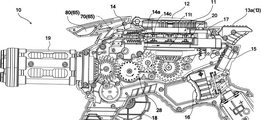
- FIG. 1 is a perspective view showing the entire effect output toy.
- the staging output toy 10 shown in FIG. 1 is a toy that imitates the shape of a machine gun used by a fighting hero of a hero such as a TV program.
- this hero is set to emit sound and light from the machine gun and transform it by attaching various attachments to the machine gun.
- "transformation” means that the clothes, form, etc. of the hero change.
- the user can play so-called “impersonator play” by impersonating the hero.
- the effect output toy 10 shown in FIG. 1 is provided with a barrel portion 19 having a plurality of muzzles 19 m on the tip end side of the toy body body 10a, and a rear pistol grip on the rear side on the lower side of the toy body body 10a.
- a front gun grip portion 10f is provided on the front side of the portion 10r
- an operation handle 18 is provided on the right side surface of the toy body body portion 10a
- a subordinate described later is provided on the upper side of the toy body body portion 10a.
- a sub-toy body mounting portion 11 (hereinafter, simply referred to as a “mounting portion”) for mounting the toy body 20 is provided.
- the sub-toy body 20 functions as an information holding medium for holding identification information.
- the auxiliary toy body 20 is prepared in a plurality of shapes having different colors and patterns, and each of them has different identification information. Therefore, by attaching the sub-toy body 20 to the effect output toy 10, it is possible to perform a desired effect according to the sub-toy body 20.
- the expressions of the directions such as up / down, front / back, left / right, etc. indicating the direction are the states when the user holds the effect output toy 10, that is, the front / rear pistol grip with the barrel portion 19 facing forward. It is assumed that the user holds the parts 10r and 10f and holds the unit 10r and 10f.
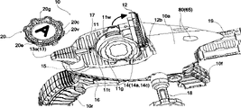
- FIG. 2 is a perspective view showing a state before the auxiliary toy body 20 is attached.
- the mounting portion 11 of the staging output toy 10 is opened forward by the opening / closing lid 12 with the hinge portion 12b as a fulcrum.
- the mounting portion 11 has a substantially cylindrical recessed structure composed of a substantially circular peripheral wall surface 11w and a rotary table 11t constituting the bottom portion.
- unevenness convex portion 20v, concave portion 20c
- a gear-like driven engagement is further formed inside.
- auxiliary toy body 20 It is a disk-shaped auxiliary toy body 20 (hereinafter referred to as “gear member”) on which a portion 20 g is formed. Then, the gear member 20 is mounted so that the driven engaging portion 20g is fitted to the driving engaging portion 11g provided on the rotary table 11t.
- FIG. 3 is a perspective view showing a state in which the gear member 20 is attached.
- the gear member 20 is mounted on the rotary table 11t.
- the opening / closing lid 12 is rotated backward to close.
- the opening / closing lid 12 is urged in the opening direction (direction opposite to the arrow in the figure) by an urging member such as a torsion spring provided on the hinge portion 12b.
- an urging member such as a torsion spring provided on the hinge portion 12b.
- the tip engaging portion 12e of the opening / closing lid 12 is locked to the tip locking portion 41, and the side projections 12d formed on the left and right side surfaces of the opening / closing lid 12 form the toy body. It is also locked to a pair of left and right protruding pieces 42 projecting from the upper surface of the body portion 10a.
- a predetermined effect can be produced by rotating the gear member 20 together with the rotary table 11t by rotating the operation handle 18 in a predetermined direction after closing the opening / closing lid 12.
- the effect is expressed based on the rotation of the gear member 20, which is a switch (first switch 14a, second switch 14c) which is a detection means to be described later and is provided so as to be in contact with the gear member 20. ) Detects the unevenness of the outer peripheral end surface 20e of the gear member 20, and a predetermined effect is performed based on this detection signal.
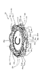
- FIG. 4 is a perspective view of the gear member 20 when viewed from the front surface side.
- the shape of the gear member 20 is a flat plate-shaped disk shape as also shown in FIG.
- a concavo-convex pattern is formed on the outer peripheral end surface 20e of the gear member 20 by the trapezoidal convex convex portion 20v and the trapezoidal concave concave portion 20c in the circumferential direction.
- this uneven pattern can be seen as eight uneven patterns when the gear member 20 is viewed from the upper surface in a plane.
- the outer peripheral end surface 20e is a first outer peripheral end surface 21e which is an upper region on the outer peripheral side surface (side wall surface) of the gear member 20 and a second outer peripheral end surface which is a lower region.
- the first concavo-convex pattern 31 is composed of the convex portions and the concave portions formed of the first outer peripheral end surface 21e along the circumferential direction, and is formed along the circumferential direction of the second outer peripheral end surface 22e.
- the second uneven pattern 32 is formed by the convex portion and the concave portion.
- different uneven patterns are formed in the upper region and the lower region divided in the stacking direction (vertical direction) in the thickness direction.
- the first uneven pattern 31 is formed by eight convex portions 20v and concave portions 20c.
- the second uneven pattern 32 is formed by one convex portion 20v (see FIG. 6) and a concave portion 20c (a concave portion that substantially goes around the outer peripheral end surface except for one convex portion). Is formed.
- the first concavo-convex pattern 31 and the second concavo-convex pattern 32 are detected separately, and are recognized by the control unit 60 (see FIG. 10) as an integrated identification pattern 30 of both concavo-convex patterns.
- a large convex portion 20vs formed by overlapping the convex portion 20v in the first unevenness pattern 31 and the convex portion 20v in the second unevenness pattern 32 is provided.
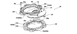
- FIG. 5 is an exploded perspective view of the gear member 20.
- the gear member 20 is composed of a plurality of disk members of the first disk member 21, the second disk member 22, and the third disk member 23.
- the first disk member 21 and the second disk member 22 are formed as annular members having a relatively large opening 20h, although they are disk members.
- the first disk member 21 and the second disk member 22 are fastened with a fixing screw 20j so as to sandwich the third disk member 23, for example.
- the convex portions 20v are formed on the first outer peripheral end surface 21e (20e) at equal intervals in the circumferential direction as described above. Therefore, the concave portions 20c are formed between the convex portions 20v, and eight concave portions 20c are also formed at equal intervals. Further, a driven engaging portion 20g in the shape of an internal gear is provided on the inner peripheral surface forming the opening 20h of the first disk member 21.
- the driven engaging portion 20g is a portion that is detachably engaged and engaged with the driving engaging portion 11g (see FIG. 2) of the mounting portion 11.
- one convex portion 20v is formed on the second outer peripheral end surface 22e (20e). Therefore, the concave portion 20c is a portion of the second outer peripheral end surface 22e other than the convex portion 20v. Further, the second disk member 22 is also provided with a driven engaged portion 20 g having the same shape as the internal gear of the first disk member 21.
- the third disk member 23 is formed as a thin plate member as compared with the other two members. Different symbols are provided on the front and back surfaces thereof, and the symbols on the front and back surfaces can be seen from the openings 20h of the first disk member 21 and the second disk member 22.
- FIG. 6 is a perspective view when viewed from the back surface side of the gear member 20.
- the convex portion 20v of the second disk member 22 is positioned so as to overlap one of the convex portions 20v on the first disk member 21 side in the thickness direction of the gear member 20, and the above-mentioned large convex portion It forms 20 vs. It is preferable that only one (one place) of the large convex portion 20 vs is formed in the gear member 20, but a plurality (multiple places) may be provided.
- the first symbol A in which the alphabet A is drawn can be seen from the first disk member 21 side, and for example B is drawn from the first disk member 21 side.
- the second symbol B can be made visible. This is different from the case where the gear member 20 is mounted so that the first symbol A can be seen and the case where the second symbol B is mounted so as to be visible when the gear member 20 is mounted on the mounting portion 11, as will be described later. It is easy to understand that the pattern 30 (different identification information) is detected.
- the uneven pattern of the upper and lower two layers of the gear member 20 is composed of an uneven pattern formed on the first disk member 21 which is a separate member and an uneven pattern formed on the second disk member 22. ..
- the same first disk member 21 and second disk member 22 can be used to create a plurality of gear members 20 having different positional relationships of irregularities.
- the pattern is such that the maximum number of convex portions 20v of the first disk member 21 is formed, there is no change even if the position of the convex portions 20v on the second disk member 22 side is changed, but for example.
- the first disk member 21 has three convex portions 20v and the second disk member 22 has four convex portions 20v, it is possible to form a pattern having different unevenness patterns depending on the angle of combination.
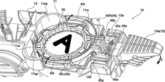
- FIG. 7 is an exploded perspective view showing the position restricting member 45 of the gear member 20.
- the opening / closing lid 12 is opened so that the gear member 20 is dropped.
- the position regulating protrusion 45t protruding from the peripheral wall surface 11w of the mounting portion 11 is located on the upper side of the outer peripheral edge of the gear member 20, so that the gear member 20 does not fall off.
- the position is regulated as such.
- the position restricting protrusion 45t moves so that the outer peripheral edge of the gear member 20 comes into contact with the peripheral wall surface 11w side, and when the gear member 20 is completely mounted, the gear member 20 moves. Return to be located above the outer perimeter.
- the position regulating protrusion 45t is provided on one end side of a pair of left and right position regulating members 45 (right position regulating member 45R, left position regulating member 45L).
- the position restricting member 45 is an arm-shaped member extending so as to surround the outside of the peripheral wall surface 11w.
- the position restricting member 45 is provided so as to be swingable with the rotation fulcrum portion 45p as a fulcrum.
- the other end 45e on the side opposite to the side where the position restricting protrusion 45t is provided is provided with a swing spring 45s that acts to push the left and right other ends 45e in the left-right direction.
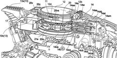
- FIG. 8 is a perspective view showing a state in which the gear member 20 is mounted on the mounting portion 11.
- the driven engaging portion 20g on the lower end side of the gear member 20 has a convex drive engaging portion 11g on the rotary table 11t. Engaged to mesh with.
- the gear member 20 is rotated in a predetermined direction together with the rotary table 11t.
- the mounting portion 11 is provided with a pair of first switches 14a and second switches 14c of the detection unit 14 so as to be in contact with each other facing the outer peripheral end surface 20e.
- the first and second switches 14a and 14c are arranged vertically with respect to the convex portions 20v of the first outer peripheral end surface 21e on the first disk member 21 side and the second outer peripheral end surface 22e on the second disk member 22 side. Can be contacted separately.
- the first switch 14a contacts the upper convex portion 20v and the second switch 14c independently contacts the lower convex portion 20v.
- the detection unit 14 here includes not only the first and second switches 14a and 14c as detection elements but also a part of the control system in the control unit 60.
- the first switch 14a and the second switch 14c have a storage wall portion 14w having two upper and lower storage chambers, slide portions 14ab and 14cc that slide in the accommodation wall portion 14w in the front-rear direction (left-right direction in the figure), and slides.
- Coil springs 14as and 14cs provided in the openings in the portions 14ab and 14cab to urge the slide portions 14ab and 14cc to the gear member 20 side, and switch portions 14am such as a micro switch corresponding to the slide portions 14ab and 14cc, respectively. It has 14 cm and.
- FIG. 9 is an exploded perspective view showing an example of an opening / closing detection switch 17 that detects the opening / closing of the opening / closing lid 12.
- the open / close detection switch 17 includes a switch main body 17a such as a micro switch, and a pressed portion 17c that is pressed by the open / close lid 12 and moves in the vertical direction.
- the pressed portion 17c is provided so as to be movable up and down in the slide accommodating portion 17w in a state of being urged upward by the pressing spring 17s.
- the lower end portion 17t of the pressed portion 17c is provided so as to be engaged with the detection end 17e of the switch body 17a, and the tip portion (upper part in the figure) of the pressed portion 17c is pushed downward. Occasionally, the detection end 17e is pushed to detect that the opening / closing lid 12 is closed.
- a protruding tip locking portion 41 surrounding the outer periphery of the tip portion of the pressed portion 17c is provided.
- a groove-shaped locking hook portion 41f recessed toward the front is formed on the outer surface of the tip locking portion 41 on the rear side (left side in the drawing). The locking hook portion 41f can be engaged with the tip engaging portion 12e of the opening / closing lid 12 so as to be hooked, and the closed state of the opening / closing lid 12 can be maintained.
- the opening / closing lid 12 is locked to the above-mentioned tip locking portion 41 in the closed state, but the left and right side projections 12d (see FIG. 3) are provided on the upper surface of the main body as a pair of left and right protruding pieces 42 (FIG. 3). 3) is also locked.
- the unlocked state of the opening / closing lid 12 is released by an operation (swing) of pushing the unlocking trigger-13a of the unlocking part 13 provided on the rear side of the toy body body 10a downward (in the direction of arrow Z).
- the front end 13e (see FIG. 7) on the opposite side of the rotary support shaft from the rear end pushed downward swings upward. .. Due to this upward swing, the block member 13b (see FIG. 8) provided so as to surround the front end portion 13e presses the main body outer wall surface member (upper surface portion) from the inside. The pressing from the inside deforms the upper surface portion of the outer wall of the toy body body 10a.
- the tip locking portion 41 and the protruding piece 42 which had locked the opening / closing lid 12, slightly move in the unlocking direction (the left and right protruding pieces 42 move so that the protruding tip side opens to the left and right, and the tip The locking portion 41 moves so as to fall forward of the gun) to release the locked state.
- the opening / closing lid 12 is opened by the urging force of the torsion spring provided on the hinge portion 12b.
- FIG. 10 is a block diagram showing a control system of the effect output toy 10 when the gear member 20 is mounted so that the first outer peripheral end surface 21e of the gear member 20 shown in FIG. 4 is arranged on the upper side.
- the effect output toy 10 has an information reading unit (in this embodiment, a first switch 14a functioning as a first detection unit and a second switch 14c functioning as a second detection unit) that reads identification information held by the gear member 20. It has a control unit 60 and the like that operate the drive unit 62 based on the identification information read by the information reading unit.
- the control unit 60 can read the operation data from the storage unit 61 and operate the drive unit 62 based on the read operation data.
- the first concavo-convex pattern 31 of the gear member 20 is detected by the combination of on and off of the first switch 14a
- the second concavo-convex pattern 32 is detected by the combination of on and off of the second switch 14c.
- the gear member 20 is identified according to the identification pattern 30 based on the combination of the first unevenness pattern 31 detected by the first switch 14a and the second unevenness pattern 32 detected by the second switch 14c. From the information, for example, information regarding the operation data recorded in the storage unit 61 can be extracted.
- the input signal when the first switch 14a and the second switch 14c detect the convex portion 20v (when the first switch 14a and the second switch 14c are turned on), for example, "1", respectively.
- the convex portion 20v is not detected (recessed portion 20c) (when the first switch 14a and the second switch 14c are off), they are recognized as "0”.
- both the first switch 14a and the second switch 14c are in contact with the convex portion 20v (the first and second switches 14a and 14c are in contact with the large convex portion 20vs and are turned on.
- the identification is started from the state). That is, when the detection signal becomes "1, 1", the ID reading start bit (recognition start) of the identification information is set.
- the timing of the end of ID reading can be, for example, the time when the second "1,1" is read.
- the end timing of ID reading when "1,1" is read from the third time onward, or when "0,0” is read from the eighth time on the gear member 20 shown in the figure (gear member). Information indicating that 20 has made one rotation) may be set as the end timing.
- the open / close detection switch 17 of the open / close lid 12 functions as an ID reset switch, and no matter how many times the gear member 20 rotates, it is recognized as the same ID until the open / close lid 12 is opened.
- the type of effect output is recorded in the storage unit 61, and the identification information corresponding to the determined identification pattern 30 is transmitted to the detection unit 14 (first and second switches 14a and 14c, and a part of the control unit 60).
- the effect is output from the output unit 65 via the drive unit 63 based on (including).
- the output unit 65 includes a sound output unit 70 such as a speaker and an optical output unit 80 using an LED or the like, and these are appropriately combined and operated.
- the power switch 15, the trigger button 16 that triggers the gun, and the open / close detection switch 17 of the open / close lid 12 are connected to the control unit 60, and a predetermined effect is produced by these switching operations.
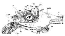
- FIG. 11 is a side view showing the internal structure of the staging output toy 10.
- FIG. 12 is a perspective view of a portion that is rotationally driven by the operation of the operation handle 18.
- the rotation of the mounting portion 11 is performed by the operation handle 18 provided outside the main body and rotating around the rotation axis CL1. This is achieved by a plurality of connecting gear portions 28 that connect the operating handle 18 and the mounting portion 11 as shown in FIGS. 11 and 12.
- the drive of the rotary table 11t is, for example, a first gear portion 28a coaxial with the operation handle 18, a second gear portion 28b meshing with the first gear portion 28a, and a third gear portion 28c coaxially integrated with the second gear portion 28b.
- the fourth gear portion 28d that meshes with the third gear portion 28c, the fifth gear portion 28e that is coaxially integrated with the fourth gear portion 28d, and the sixth gear portion 28f that is coaxially integrated with the fifth gear portion 28e and the rotary table 11t. It is done via.
- the fifth gear portion 28e and the sixth gear portion 28f are composed of cap tooth gears as shown in FIG.
- the rotation of the rotary table 11t can be set to the rotation axis CL2 that is orthogonal to the rotation axis CL1 of the operation handle 18 in the vertical direction.
- the weight of the operation handle 18 at the time of rotation can be set to a predetermined value, and the rotation operation feeling of the operation handle 18 can be obtained. Further, it is easy to set the rotation speed of the operation handle 18 and the rotation speed of the rotary table 11t.
- the barrel portion 19 is configured on the toy body body portion 10a as a rotating portion that can rotate around the rotation axis CL3.
- the drive of the barrel portion 19 is, for example, with the seventh gear portion 28g that meshes with the first gear portion 28a, the eighth gear portion 28h coaxially integrated with the seventh gear portion 28g, the eighth gear portion 28h, and the barrel portion 19. This is done via a coaxially integrated ninth gear portion 28i.
- the eighth gear portion 28h and the ninth gear portion 28i are composed of cap tooth gears, the rotation of the rotation axis CL3 is in the front-rear direction with respect to the rotation axis CL1 of the operation handle 18. It is orthogonal.
- FIG. 13 is an exploded perspective view of the mounting portion of the operation handle 18.
- the operation handle 18 is configured to be removable from the handle mounting portion 28t on the toy body body 10a side.
- the operation handle 18 is rotatably provided at the tip of the mounting portion 18t to be mounted so as to coincide with the rotation axis CL1, the arm portion 18m extending in the direction orthogonal to the rotation axis CL1, and the tip of the arm portion 18m. It is provided with a grip portion of 18 g.
- the handle mounting portion 28t has a first rotating portion 28k on the first gear portion 28a side and a second rotating portion 28j that engages with the mounting portion 18t.
- the second rotating portion 28j is provided with an engaging projection 28jj so that the second rotating portion 28j can engage with the end surface 18e of the mounting portion 18t to transmit the rotational force.
- the first rotating portion 28k and the second rotating portion 28j are configured so that the ratchet engaging portion 28p engages in rotation in only one direction and can transmit the rotational force.
- the first rotating portion 28k and the second rotating portion 28j are provided on the same rotation axis.
- the first rotating portion 28k is provided so as to be integrally rotatable with respect to the first gear portion 28a and slidable along the rotation axis CL1 (in the direction of arrow X). Further, the first rotating portion 28k is urged by a coil spring (not shown) in a direction away from the first gear portion 28a (direction pressed against the second rotating portion 28j).
- the ratchet engaging portion 28p for example, when the toy body body portion 10a is viewed from the right direction, the first rotating portion 28k and the second rotating portion 28j are integrated in the clockwise direction (arrow C direction). It works to rotate in a positive manner.
- the ratchet engaging portion 28p is disengaged from the ratchet engaging portion 28p due to the engagement of the inclined surfaces between the two rotating portions 28k and 28j, and the second rotating portion 28j slips.
- the rotary table 11t and the barrel portion 19 can rotate in only one direction.
- the power switch 15 When playing the production output toy 10, first, the power switch 15 is turned on. This produces a start-up sound. When the effect of the start-up sound is performed, for example, the operation of the trigger button 16 is invalidated, and the effect output is not generated even if the trigger button 16 is operated. After that, when the trigger button 16 is operated without loading (mounting) the gear member 20, for example, an attack sound or the like is generated.
- the opening / closing lid 12 is opened.
- an opening sound (detected by the open / close detection switch 17) is generated.
- the gear member 20 is loaded, for example, with the A side facing up and the open / close lid 12 is closed, for example, it is detected that the open / close lid 12 is closed (detected by the open / close detection switch 17), and the gear member 20 is used. It produces a gear loading sound that indicates that it has been loaded.
- the operation handle 18 is rotated to rotate the loaded gear member 20.
- a gear rotation standby sound is generated. By rotating the operation handle 18, the barrel portion 19 is also rotated.
- the gear rotation standby sound starts to be expressed by detecting that the rotation operation has been started by using, for example, the first switch 14a and the second switch 14c. After the gear rotation standby sound is generated for a predetermined time, a gear detection sound indicating that the gear member 20 is detected is generated.
- the first switch 14a and the second switch 14c are turned on and off by the uneven pattern (identification pattern 30), and based on the combination of the first switch 14a and the second switch 14c on and off, the first switch 14a and the second switch 14c are turned on and off.
- the identification pattern 30 is recognized and the ID (identification information) of the gear member 20 is detected.
- the effect corresponding to the ID is expressed.
- the trigger button 16 is briefly pressed (pressed and immediately released), for example, an attack sound by a hero is generated.
- a charge attack which is a particularly powerful attack
- a maximum charge attack is expressed for a predetermined time from the charge attack.
- a Gatling sound (a shooting sound of a Gatling gun) is generated along with the rotation of the barrel portion 19.
- this gear member 20 is provided with a wide variety of uneven patterns that differ for each hero, and it is possible to load different hero gear members 20 and play with different effects for each hero. Further, the colors and patterns of the gear member 20 are distinguished by different emblems for each hero, and the change can be enjoyed by this.
- the first switch 14a and the second switch 14c detect an ID different from that when the A side faces up. .. Even with the same gear member 20, different effects can be exhibited. In short, you can enjoy the production of twice the number of prepared gear members 20.
- the gear member 20 having the identification pattern 30 is mounted on the identification pattern 30 with the front and back surfaces changed so that the identification pattern 30 can be read by the detection unit 14. Since the identification information based on the above can be changed, a plurality of effect outputs can be output based on one gear member 20.
- the gear member 20 is a flat plate
- the space of the gear member 20 can be saved, and the front and back surfaces can be distinguished, for example, the symbols of the front and back surfaces A and B. Changes such as changes can make it easier to recognize the front and back.
- the identification pattern 30 is formed by the uneven pattern formed on the outer peripheral end surface 20e of the flat plate, the region having the maximum length in the gear member 20 can be used as the uneven pattern forming region. As a result, the size of the uneven pattern can be increased and the number of formations can be increased.
- the gear member 20 since the uneven pattern is provided on the outer peripheral end surface 20e, easily visible information can be displayed (design, emblem) on the front and back surfaces A and B of the gear member 20. Further, the gear member 20 can produce a mechanical shape having a gear shape due to unevenness as an appearance.
- the gear member 20 since the gear member 20 is configured in a disk shape, it becomes easy to rotate and use it. As a result, the rotation of the gear member 20 can be used to read the identification information of the unevenness pattern, and the information can be easily read.
- the gear member 20 is provided with a plurality of layers of uneven patterns in the thickness direction of the gear member 20, so that more patterns can be formed.
- the gear member 20 is a superposition of a plurality of disk members (first disk member 21 and second disk member 22), an uneven pattern is formed for each disk member. It can be formed, and it is easy to form an uneven pattern. Further, even if the combination of the first disk member 21 and the second disk member 22 to be laminated is the same, by changing the relative angle in the circumferential direction of both disk members and combining them, a different identification pattern 30 is provided as a whole.
- the gear member 20 can be used.
- the concave-convex pattern in each concave-convex pattern formed in a plurality of layers, can be read at one starting position by setting the overlapped portion 20v at one location. For example, when the contact type first and second switches 14a and 14c in contact with the convex portion 20v are provided, all the switches (first and second switches 14a and 14c) are convex at the same position when the gear member 20 is rotated. It is turned on by the unit 20v, and by using this on operation as the starting point for reading the pattern array, the reading and analysis of the pattern array becomes easy. Further, one place where the convex portions 20v overlap can be set as the end position of reading the concave-convex pattern. As a result, the starting point and the ending point of ID reading are clarified, and more reliable reading can be performed.
- the rotational driving force is transmitted between the operation handle 18 provided on the effect output toy 10 and the mounting portion 11 via the connecting gear portion 28.
- the orientation of the rotation surface of the operation handle 18 and the rotation surface of the mounting portion 11 can be arbitrarily set, and the degree of freedom in the orientation and positional relationship between the operation handle 18 and the mounting portion 11 can be increased.
- the rotation operation of the operation handle 18 and the rotation ratio of the gear member 20 can be freely set by using the connecting gear portion 28, the rotation resistance of the operation handle 18 and the like can be set, and the rotation operation feeling of the operation handle 18 can be set. Can be produced.
- the mounting portion 11 includes a drive engaging portion 11g that engages with the front and back surfaces (A side, B side) of the gear member 20, so that the gear member 20 is It is not necessary to use the outer peripheral end surface 20e as a driving portion, and the entire surface of the outer peripheral end surface 20e can be used as a region for forming an uneven pattern. Further, since the driven engaging portion 20g of the gear member 20 has an internal tooth-shaped uneven shape on the front and back surfaces, it is possible to produce a mechanical shape of the gear member 20 in combination with the uneven pattern of the outer peripheral end surface 20e.
- the connecting gear portion 28 can rotate the barrel portion 19 in conjunction with the rotation of the mounting portion 11.
- the barrel portion 19 can perform a rotation effect at the same time as the rotation of the gear member 20, and various effects can be produced.
- the distance between the outer peripheral end surface 20e of the gear member 20 and the peripheral wall surface 11w facing the outer peripheral end surface 20e is a gap having a size equal to or larger than a predetermined value. Since the 11sp is provided, for example, the fingertip can enter the gap 11sp, and the operability when removing the gear member 20 from the mounting portion 11 can be improved.
- the operation handle 18 since the operation handle 18 is configured so that the mounting portion 11 can rotate only in one direction, the reading direction of the uneven pattern of the gear member 20 is determined. As a result, erroneous reading of the identification pattern 30 can be avoided.
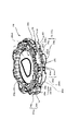
- FIG. 14 is a perspective view of the gear member 20 having a variation different from that of FIG. 4 when viewed from the front surface side.
- the gear member 20 has a substantially circular outer circumference and has a flat disk shape.
- the shape of the gear member 20 is not limited to this, and may be a polygon such as a rectangle, or may have a shape in which the upper surface or the lower surface is bulged.
- the outer peripheral end surface 20e of the gear member 20 is a region where a concave portion and a convex portion forming identification information of the gear member 20 are formed, and here, a trapezoidal convex convex portion 20v and a trapezoidal concave concave portion are formed along the circumferential direction. An uneven pattern formed by 20c is formed.
- the outer peripheral end surface 20e of the gear member 20 is divided into two upper and lower regions when viewed from the side (thickness direction), the first outer peripheral end surface 21e in the upper region and the second region in the lower region. It is composed of an outer peripheral end surface 22e.
- the concave and convex portions formed on the first outer peripheral end surface 21e and the concave and convex portions formed on the second outer peripheral end surface 22e are formed independently of each other. That is, the first unevenness pattern 31 is formed by the convex portions and concave portions formed along the circumferential direction of the first outer peripheral end surface 21e, and the convex portions and concave portions formed along the circumferential direction of the second outer peripheral end surface 22e.
- the second uneven pattern 32 is configured.
- the gear member 20 has different uneven patterns formed in the thickness direction. Note that FIG. 14 shows an example in which the outer peripheral end surface 20e has two stages of upper and lower regions, but the present invention is not limited to this, and only one stage may be used, or three or more stages may be formed.
- a region may be provided. Further, the concave portion and the convex portion formed on the first outer peripheral end surface 21e and the concave portion and the convex portion formed on the second outer peripheral end surface 22e are formed of separate members, but the present invention is not limited thereto.
- the uneven portion may be integrally formed by one member such that the first disk member 21 and the second disk member 22 are integrated.
- the first unevenness pattern 31 is formed by the four convex portions 20v and the concave portions 20c.
- the second uneven pattern 32 is formed by the five convex portions 20v and the concave portions 20c.
- the first concavo-convex pattern 31 and the second concavo-convex pattern 32 are detected separately, and are recognized by the control unit 60 (see FIG. 10) as an integrated identification pattern 30 of both concavo-convex patterns.
- a large convex portion 20vs formed by overlapping the convex portion 20v in the first unevenness pattern 31 and the convex portion 20v in the second unevenness pattern 32 is provided.
- the concave portions and the convex portions appear alternately. It has become.
- a region 20vk in which a convex portion is not formed is provided in a part between the two concave portions 20c, and corresponds to the region 20vk in the lower second outer peripheral end surface 22e.
- a convex portion 20v is provided at the position.
- a region 20vk in which a convex portion is not formed is provided in a part between the two concave portions 20c, and at a position corresponding to the region 20vk in the upper first outer peripheral end surface 21e. Is provided with a convex portion 20v.
- a convex portion 20v is formed on either the upper first outer peripheral end surface 21e or the lower second outer peripheral end surface 22e, and in the present embodiment, the first unevenness is formed.
- the pattern 31 and the second uneven pattern 32 can be detected as 16-bit signals, respectively.
- the convex portion 20v is always formed between the concave portions 20c of either the upper first outer peripheral end surface 21e or the lower second outer peripheral end surface 22e, so that the first unevenness pattern 31 or the pattern 32 is formed.
- the identification pattern 30 to be used can be definitely recognized.
- FIG. 15 is an exploded perspective view of the gear member 20 shown in FIG.
- the gear member 20 is composed of a plurality of disk members of the first disk member 21, the second disk member 22, and the third disk member 23.
- the first disk member 21 and the second disk member 22 are formed as annular members having a relatively large opening 20h, although they are disk members.
- the first disk member 21 and the second disk member 22 are fastened with a fixing screw 20j so as to sandwich the third disk member 23, for example.
- the first outer peripheral end surface 21e (20e) is formed with four convex portions 20v in the circumferential direction and four regions 20vk where no convex portions are formed. Further, the concave portions 20c are formed between the convex portions 20v or the regions 20vk, and are formed at eight places at equal intervals. Further, a driven engaging portion 20g in the shape of an internal gear is provided on the inner peripheral surface forming the opening 20h of the first disk member 21.
- the driven engaging portion 20g is a portion that is detachably engaged and engaged with the driving engaging portion 11g (see FIG. 2) of the mounting portion 11.
- the second outer peripheral end surface 22e (20e) is formed with five convex portions 20v and three regions 20vk where no convex portions are formed. Further, the concave portions 20c are formed between the convex portions 20v or the regions 20vk, and are formed at eight places at equal intervals. Further, the second disk member 22 is also provided with a driven engaged portion 20 g having the same shape as the internal gear of the first disk member 21.
- the third disk member 23 is formed as a thin plate member as compared with the other two members. Different symbols are provided on the front and back surfaces thereof, and the symbols on the front and back surfaces can be seen from the openings 20h of the first disk member 21 and the second disk member 22.
- FIG. 16 is a perspective view of the gear member 20 shown in FIG. 14 when viewed from the back surface side.
- the convex portion 20v of the second disk member 22 is positioned so as to overlap one of the convex portions 20v on the first disk member 21 side in the thickness direction of the gear member 20, and the above-mentioned large convex portion It forms 20 vs. It is preferable that only one (one place) of the large convex portion 20 vs is formed in the gear member 20, but a plurality of (multiple places) may be provided.
- the first symbol C in which the alphabet C is drawn can be seen from the first disk member 21 side, and the alphabet D is drawn from the first disk member 21 side.
- the second symbol D can be made visible.
- this symbol is not a simple C or D as shown in the figure, but an effective effect in which the gear member 20 and the effect output are associated with each other by showing a pattern corresponding to the effect output (for example, a hero's emblem). Is possible.
- the concave portion and the convex portion are formed in the same arrangement in the left and right regions with respect to the line segment drawn from the center of the gear member 20 to the large convex portion 20vs, and the convex portion 20v is symmetrically formed. (Region 20vk) is formed.
- the convex portion 20v (concave portion 20c) is formed symmetrically in this way, a special effect may be output from the effect output toy, and a more versatile effect is possible.
- the convex portion 20v is provided at a position facing the large convex portion 20vs, and the second outer peripheral end surface 22e (20e) is provided with the convex portion 20v.
- a region 20vk where no convex portion is formed is formed.
- the convex portion 20v and the region 20vk are provided at positions facing the large convex portion 20vs, but the present invention is not limited to this and can be appropriately set, preferably the convex portion 20v. , It is preferable to provide it at the position of the intermediate position (intermediate bit) of the uneven pattern composed of the region 20vk or the concave portion 20c.
- the unevenness detecting means of the gear member 20 may be a non-contact detection sensor instead of the contact type switch (first switch 14a, second switch 14c) of the above embodiment.
- the number of convex portions 20v of the first outer peripheral end surface 21e of the gear member 20 is 8 or 4, and the number of convex portions 20v of the second outer peripheral end surface 22e is 1 or 5.
- the number of irregularities is not limited, and the number of irregularities can be appropriately changed.
- the gear member 20 has two upper and lower layers in the thickness direction for forming the uneven pattern, but may be a plurality of three or more layers, or may be only one layer. good.
- first disk member 21 and the second disk member 22 of the gear member 20 are composed of an annular member, but the gear member 20 does not necessarily have to be an annular member.
- the rotation direction of the gear member 20 is only one direction, but the gear member 20 may also be rotated in the reverse direction.
- the opening / closing lid 12 may be composed of a light-transmitting (transparent or translucent) member so that the mounted gear member 20 can be seen. In this case, the rotational operation of the gear member 20 can be seen, and the effect of the effect can be enhanced.
- the operation handle 18 has a detachable structure, but the structure is not limited to this.
- a hinge structure may be provided on the arm portion 18 m so that the arm portion can be folded.
- the outer surface of the toy body body 10a is provided with a recessed portion capable of accommodating the arm portion 18 m and the grip portion 18 g, so that the arm portion 18 m and the grip portion 18 g can be accommodated in this recessed portion. Is also good.
Landscapes
- Physics & Mathematics (AREA)
- Engineering & Computer Science (AREA)
- Acoustics & Sound (AREA)
- Multimedia (AREA)
- Toys (AREA)
Priority Applications (1)
| Application Number | Priority Date | Filing Date | Title |
|---|---|---|---|
| KR1020237016830A KR102840297B1 (ko) | 2020-12-02 | 2021-10-18 | 정보 유지 매체 및 연출 출력 완구 |
Applications Claiming Priority (2)
| Application Number | Priority Date | Filing Date | Title |
|---|---|---|---|
| JP2020-200285 | 2020-12-02 | ||
| JP2020200285A JP6998443B1 (ja) | 2020-12-02 | 2020-12-02 | 情報保持媒体および演出出力玩具 |
Publications (1)
| Publication Number | Publication Date |
|---|---|
| WO2022118547A1 true WO2022118547A1 (ja) | 2022-06-09 |
Family
ID=80469010
Family Applications (1)
| Application Number | Title | Priority Date | Filing Date |
|---|---|---|---|
| PCT/JP2021/038458 Ceased WO2022118547A1 (ja) | 2020-12-02 | 2021-10-18 | 情報保持媒体および演出出力玩具 |
Country Status (4)
| Country | Link |
|---|---|
| JP (3) | JP6998443B1 (enExample) |
| KR (1) | KR102840297B1 (enExample) |
| CN (2) | CN114307196B (enExample) |
| WO (1) | WO2022118547A1 (enExample) |
Families Citing this family (2)
| Publication number | Priority date | Publication date | Assignee | Title |
|---|---|---|---|---|
| JP7738117B1 (ja) | 2024-03-21 | 2025-09-11 | 株式会社バンダイ | 模型玩具、及び模型部品 |
| JP7679527B1 (ja) * | 2024-06-12 | 2025-05-19 | 株式会社バンダイ | 動作玩具 |
Citations (4)
| Publication number | Priority date | Publication date | Assignee | Title |
|---|---|---|---|---|
| JP2010119504A (ja) * | 2008-11-18 | 2010-06-03 | Agatsuma:Kk | 知育玩具 |
| JP2012096026A (ja) * | 2011-10-07 | 2012-05-24 | Bandai Co Ltd | 情報読取玩具 |
| JP2018033979A (ja) * | 2017-10-13 | 2018-03-08 | 株式会社バンダイ | 読取体 |
| JP2019146784A (ja) * | 2018-02-27 | 2019-09-05 | 株式会社タカラトミー | 発音玩具 |
Family Cites Families (13)
| Publication number | Priority date | Publication date | Assignee | Title |
|---|---|---|---|---|
| JPH0421196A (ja) * | 1990-05-16 | 1992-01-24 | Hitachi Ltd | 情報記録媒体 |
| JPH10255333A (ja) * | 1997-03-11 | 1998-09-25 | Mitsubishi Electric Corp | 円環状記録媒体及び該円環状記録媒体の媒体カバー及び該円環状記録媒体の媒体駆動装置 |
| JP2004219956A (ja) * | 2003-01-17 | 2004-08-05 | Takara Co Ltd | オルゴール玩具 |
| JP4253020B2 (ja) | 2007-02-14 | 2009-04-08 | 株式会社バンダイ | ゲーム装置 |
| JP2013141563A (ja) * | 2012-01-12 | 2013-07-22 | President Japan Kk | 対戦ゲーム玩具 |
| JP5694587B1 (ja) * | 2014-04-14 | 2015-04-01 | 株式会社バンダイ | 演出出力玩具 |
| JP5802322B1 (ja) * | 2014-12-02 | 2015-10-28 | 株式会社バンダイ | 演出玩具 |
| JP6085055B1 (ja) * | 2016-06-08 | 2017-02-22 | 株式会社バンダイ | 演出出力玩具 |
| JP6304843B2 (ja) * | 2016-11-24 | 2018-04-04 | 株式会社バンダイ | 動作玩具 |
| JP6232154B1 (ja) * | 2017-03-10 | 2017-11-15 | 株式会社タカラトミー | 回転速度検出装置 |
| JP6660916B2 (ja) * | 2017-05-31 | 2020-03-11 | 株式会社バンダイ | 演出出力玩具 |
| JP6890196B2 (ja) * | 2017-06-29 | 2021-06-18 | 株式会社バンダイ | 情報処理装置およびシステム |
| JP2017225837A (ja) * | 2017-08-22 | 2017-12-28 | 株式会社バンダイ | 演出出力玩具及び演出出力玩具に適用される物品 |
-
2020
- 2020-12-02 JP JP2020200285A patent/JP6998443B1/ja active Active
-
2021
- 2021-10-18 KR KR1020237016830A patent/KR102840297B1/ko active Active
- 2021-10-18 WO PCT/JP2021/038458 patent/WO2022118547A1/ja not_active Ceased
- 2021-11-29 CN CN202111433900.1A patent/CN114307196B/zh active Active
- 2021-11-29 CN CN202410390959.4A patent/CN118304661A/zh active Pending
- 2021-12-20 JP JP2021205872A patent/JP7672329B2/ja active Active
-
2025
- 2025-04-22 JP JP2025070078A patent/JP2025105758A/ja active Pending
Patent Citations (4)
| Publication number | Priority date | Publication date | Assignee | Title |
|---|---|---|---|---|
| JP2010119504A (ja) * | 2008-11-18 | 2010-06-03 | Agatsuma:Kk | 知育玩具 |
| JP2012096026A (ja) * | 2011-10-07 | 2012-05-24 | Bandai Co Ltd | 情報読取玩具 |
| JP2018033979A (ja) * | 2017-10-13 | 2018-03-08 | 株式会社バンダイ | 読取体 |
| JP2019146784A (ja) * | 2018-02-27 | 2019-09-05 | 株式会社タカラトミー | 発音玩具 |
Also Published As
| Publication number | Publication date |
|---|---|
| CN114307196A (zh) | 2022-04-12 |
| JP6998443B1 (ja) | 2022-01-18 |
| CN118304661A (zh) | 2024-07-09 |
| CN114307196B (zh) | 2024-03-12 |
| JP2025105758A (ja) | 2025-07-10 |
| KR20230091946A (ko) | 2023-06-23 |
| KR102840297B1 (ko) | 2025-07-30 |
| JP7672329B2 (ja) | 2025-05-07 |
| JP2022088051A (ja) | 2022-06-14 |
| JP2022088353A (ja) | 2022-06-14 |
Similar Documents
| Publication | Publication Date | Title |
|---|---|---|
| JP2025105758A (ja) | 情報保持媒体および演出出力玩具 | |
| JP7375095B2 (ja) | 演出出力玩具 | |
| CN104941215B (zh) | 动作响应玩具及玩具体 | |
| JP4872019B1 (ja) | 動作玩具 | |
| KR101306999B1 (ko) | 완구 | |
| JP7144575B1 (ja) | 演出出力玩具 | |
| CN110141872B (zh) | 动作玩具 | |
| CN112704886A (zh) | 演出输出玩具 | |
| JP7665664B2 (ja) | 演出出力玩具 | |
| JP7745700B2 (ja) | 動作玩具 | |
| JP2022027793A (ja) | 玩具 | |
| JP2006346220A (ja) | 遊戯玩具 | |
| JP6480552B1 (ja) | 演出出力玩具、及び演出出力玩具用の物品 | |
| JP2020078555A (ja) | 演出出力玩具、演出出力玩具セット、及び演出出力玩具用の操作具 | |
| JP6738950B2 (ja) | 動作応答玩具 | |
| JP2018019994A (ja) | 動作玩具 | |
| JP7793100B1 (ja) | 演出出力玩具、および副玩具体 | |
| JP7793101B1 (ja) | 演出出力玩具、および副玩具体 | |
| JP7622150B1 (ja) | 演出出力玩具、遊技媒体、および玩具別体 | |
| JP6707701B1 (ja) | アクションロボット玩具 | |
| TWI309052B (enExample) | ||
| HK40005861B (zh) | 动作玩具 | |
| KR20130003185U (ko) | 다기능 핸드폰 완구 |
Legal Events
| Date | Code | Title | Description |
|---|---|---|---|
| 121 | Ep: the epo has been informed by wipo that ep was designated in this application |
Ref document number: 21900303 Country of ref document: EP Kind code of ref document: A1 |
|
| ENP | Entry into the national phase |
Ref document number: 20237016830 Country of ref document: KR Kind code of ref document: A |
|
| NENP | Non-entry into the national phase |
Ref country code: DE |
|
| 122 | Ep: pct application non-entry in european phase |
Ref document number: 21900303 Country of ref document: EP Kind code of ref document: A1 |