WO2022114018A1 - インクジェット記録装置 - Google Patents
インクジェット記録装置 Download PDFInfo
- Publication number
- WO2022114018A1 WO2022114018A1 PCT/JP2021/043034 JP2021043034W WO2022114018A1 WO 2022114018 A1 WO2022114018 A1 WO 2022114018A1 JP 2021043034 W JP2021043034 W JP 2021043034W WO 2022114018 A1 WO2022114018 A1 WO 2022114018A1
- Authority
- WO
- WIPO (PCT)
- Prior art keywords
- head
- ink
- heads
- processing
- post
- Prior art date
Links
- 239000007788 liquid Substances 0.000 claims abstract description 342
- 238000012545 processing Methods 0.000 claims abstract description 164
- 238000007781 pre-processing Methods 0.000 claims abstract description 128
- 238000011144 upstream manufacturing Methods 0.000 claims abstract description 102
- 230000032258 transport Effects 0.000 claims description 202
- 238000012805 post-processing Methods 0.000 claims description 195
- 238000007599 discharging Methods 0.000 claims description 11
- 230000015572 biosynthetic process Effects 0.000 claims description 10
- 239000000976 ink Substances 0.000 description 728
- 238000007639 printing Methods 0.000 description 51
- 238000000034 method Methods 0.000 description 46
- 238000012423 maintenance Methods 0.000 description 18
- 230000001965 increasing effect Effects 0.000 description 17
- 239000011295 pitch Substances 0.000 description 17
- 239000003086 colorant Substances 0.000 description 15
- 230000008569 process Effects 0.000 description 14
- 238000012546 transfer Methods 0.000 description 10
- 230000008859 change Effects 0.000 description 9
- 230000000052 comparative effect Effects 0.000 description 8
- 230000001133 acceleration Effects 0.000 description 7
- 238000010586 diagram Methods 0.000 description 7
- 238000002203 pretreatment Methods 0.000 description 7
- 230000000694 effects Effects 0.000 description 6
- 238000011161 development Methods 0.000 description 5
- 239000000049 pigment Substances 0.000 description 5
- 239000004744 fabric Substances 0.000 description 4
- 239000011347 resin Substances 0.000 description 4
- 229920005989 resin Polymers 0.000 description 4
- 238000004804 winding Methods 0.000 description 4
- 238000011156 evaluation Methods 0.000 description 3
- 238000007641 inkjet printing Methods 0.000 description 3
- 239000002904 solvent Substances 0.000 description 3
- 230000002457 bidirectional effect Effects 0.000 description 2
- 230000005611 electricity Effects 0.000 description 2
- 238000007654 immersion Methods 0.000 description 2
- 230000005499 meniscus Effects 0.000 description 2
- 238000005507 spraying Methods 0.000 description 2
- XLYOFNOQVPJJNP-UHFFFAOYSA-N water Substances O XLYOFNOQVPJJNP-UHFFFAOYSA-N 0.000 description 2
- 239000002759 woven fabric Substances 0.000 description 2
- 238000012935 Averaging Methods 0.000 description 1
- 240000006829 Ficus sundaica Species 0.000 description 1
- 239000011230 binding agent Substances 0.000 description 1
- 125000002091 cationic group Chemical group 0.000 description 1
- 239000000470 constituent Substances 0.000 description 1
- 230000002708 enhancing effect Effects 0.000 description 1
- 238000002474 experimental method Methods 0.000 description 1
- 239000000835 fiber Substances 0.000 description 1
- 230000020169 heat generation Effects 0.000 description 1
- 238000010438 heat treatment Methods 0.000 description 1
- 230000007246 mechanism Effects 0.000 description 1
- 239000002985 plastic film Substances 0.000 description 1
- 229920001296 polysiloxane Polymers 0.000 description 1
- 238000007790 scraping Methods 0.000 description 1
- 239000004753 textile Substances 0.000 description 1
Images


Classifications
-
- B—PERFORMING OPERATIONS; TRANSPORTING
- B41—PRINTING; LINING MACHINES; TYPEWRITERS; STAMPS
- B41J—TYPEWRITERS; SELECTIVE PRINTING MECHANISMS, i.e. MECHANISMS PRINTING OTHERWISE THAN FROM A FORME; CORRECTION OF TYPOGRAPHICAL ERRORS
- B41J11/00—Devices or arrangements of selective printing mechanisms, e.g. ink-jet printers or thermal printers, for supporting or handling copy material in sheet or web form
- B41J11/0015—Devices or arrangements of selective printing mechanisms, e.g. ink-jet printers or thermal printers, for supporting or handling copy material in sheet or web form for treating before, during or after printing or for uniform coating or laminating the copy material before or after printing
-
- B—PERFORMING OPERATIONS; TRANSPORTING
- B41—PRINTING; LINING MACHINES; TYPEWRITERS; STAMPS
- B41J—TYPEWRITERS; SELECTIVE PRINTING MECHANISMS, i.e. MECHANISMS PRINTING OTHERWISE THAN FROM A FORME; CORRECTION OF TYPOGRAPHICAL ERRORS
- B41J2/00—Typewriters or selective printing mechanisms characterised by the printing or marking process for which they are designed
- B41J2/005—Typewriters or selective printing mechanisms characterised by the printing or marking process for which they are designed characterised by bringing liquid or particles selectively into contact with a printing material
- B41J2/01—Ink jet
- B41J2/21—Ink jet for multi-colour printing
- B41J2/2107—Ink jet for multi-colour printing characterised by the ink properties
- B41J2/2114—Ejecting specialized liquids, e.g. transparent or processing liquids
-
- B—PERFORMING OPERATIONS; TRANSPORTING
- B41—PRINTING; LINING MACHINES; TYPEWRITERS; STAMPS
- B41J—TYPEWRITERS; SELECTIVE PRINTING MECHANISMS, i.e. MECHANISMS PRINTING OTHERWISE THAN FROM A FORME; CORRECTION OF TYPOGRAPHICAL ERRORS
- B41J29/00—Details of, or accessories for, typewriters or selective printing mechanisms not otherwise provided for
- B41J29/12—Guards, shields or dust excluders
- B41J29/13—Cases or covers
-
- B—PERFORMING OPERATIONS; TRANSPORTING
- B41—PRINTING; LINING MACHINES; TYPEWRITERS; STAMPS
- B41J—TYPEWRITERS; SELECTIVE PRINTING MECHANISMS, i.e. MECHANISMS PRINTING OTHERWISE THAN FROM A FORME; CORRECTION OF TYPOGRAPHICAL ERRORS
- B41J29/00—Details of, or accessories for, typewriters or selective printing mechanisms not otherwise provided for
- B41J29/38—Drives, motors, controls or automatic cut-off devices for the entire printing mechanism
Definitions
- the present disclosure relates to an inkjet recording apparatus equipped with an ink head mounted on a carriage that moves in the main scanning direction.
- An inkjet recording device such as an inkjet printer is provided with an ink head that ejects ink for image formation toward a recording medium.
- the recording medium is a fiber sheet such as a woven fabric or a knitted fabric or a plastic sheet
- a pretreatment liquid / posttreatment liquid to the recording medium before and after ejecting the ink toward the recording medium.
- the pretreatment liquid is, for example, a treatment liquid for improving the fixing property of the ink on the recording medium and the cohesiveness of the ink pigment.
- the post-treatment liquid is, for example, a treatment liquid that enhances the fastness of a printed image.
- the inkjet recording device is provided with a processing head for discharging the pretreatment liquid and the posttreatment liquid in addition to the ink head.
- the ink head and each processing head are mounted on a carriage that reciprocates in the main scanning direction.
- the recording medium is intermittently fed in a predetermined transport direction (sub-scanning direction), and the carriage is reciprocated in the main scanning direction while the recording medium is stopped.
- a predetermined transport direction sub-scanning direction
- the carriage is reciprocated in the main scanning direction while the recording medium is stopped.
- the inkjet recording apparatus includes a transport unit, a carriage, one or more ink head rows, and a processing head.
- the transport unit transports the recording medium in a predetermined transport direction.
- the carriage reciprocates in the main scanning direction intersecting the transport direction.
- the one or more rows of ink heads are mounted on the carriage at predetermined positions in the transport direction.
- the processing head is mounted on the carriage and discharges a non-color-developing processing liquid.
- Each of the one or more ink head rows includes a plurality of ink heads arranged so as to be aligned in the main scanning direction to eject ink for image formation.
- the processing head includes a pretreatment head that is arranged upstream of the one or more ink head rows in the transport direction and discharges the pretreatment liquid that is the treatment liquid.
- the head arranged on the one end side in the main scanning direction is defined as the one end side head
- the head arranged on the other end side is defined as the other end side head.
- the inkjet recording apparatus includes a transport unit, a carriage, one or more ink head rows, and a processing head.
- the transport unit transports the recording medium in a predetermined transport direction.
- the carriage reciprocates in the main scanning direction intersecting the transport direction.
- the one or more rows of ink heads are mounted on the carriage at predetermined positions in the transport direction.
- the processing head is mounted on the carriage and discharges a non-color-developing processing liquid.
- Each of the one or more ink head rows includes a plurality of ink heads arranged so as to be aligned in the main scanning direction to eject ink for image formation.
- the processing head includes a post-processing head that is arranged on the downstream side of the one or more ink head rows in the transport direction and discharges the post-processing liquid that is the processing liquid.
- the head arranged on the one end side in the main scanning direction is defined as the one end side head
- the head arranged on the other end side is defined as the other end side head.
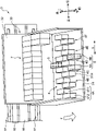
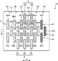
- FIG. 1 is a perspective view showing an overall configuration of an inkjet printer according to an embodiment of the present disclosure.
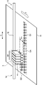
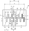
- FIG. 2 is a schematic cross-sectional view taken along line II-II of FIG.
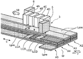
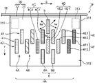
- FIG. 3 is an enlarged perspective view of the carriage shown in FIG.
- FIG. 4 is a schematic diagram showing a serial printing method adopted in the present embodiment.
- FIG. 5A is a schematic diagram showing a printing situation on the outward path and the return path of the carriage.
- FIG. 5B is a schematic diagram showing a printing situation on the outward path and the return path of the carriage.
- FIG. 6 is a plan view schematically showing the head arrangement according to the first embodiment, showing the arrangement of the ink head and the processing head in the carriage shown in FIG. FIG.
- FIG. 7 is a schematic diagram for explaining the landing time of the pretreatment liquid, the ink, and the posttreatment liquid at the point P on the recording medium.
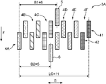
- FIG. 8 is a plan view of the carriage showing the head arrangement according to the second embodiment.
- FIG. 9 is a plan view of the carriage showing the head arrangement according to the third embodiment.
- FIG. 10 is a plan view of the carriage showing the head arrangement according to the fourth embodiment.
- FIG. 11 is a plan view of the carriage showing the head arrangement according to the fifth embodiment.
- FIG. 12 is a plan view of the carriage showing the head arrangement according to the sixth embodiment.
- FIG. 13 is a plan view of the carriage showing the head arrangement according to the seventh embodiment.
- FIG. 14 is a plan view of the carriage showing the head arrangement according to the eighth embodiment.
- FIG. 8 is a plan view of the carriage showing the head arrangement according to the second embodiment.
- FIG. 9 is a plan view of the carriage showing the head arrangement according to the third embodiment.
- FIG. 10 is a plan view
- FIG. 15 is a plan view of the carriage showing the head arrangement and the sub tank arrangement according to the ninth embodiment.
- FIG. 16 is a plan view of the carriage showing the head arrangement according to the tenth embodiment.
- FIG. 17 is a plan view of the carriage showing the head arrangement according to the eleventh embodiment.
- FIG. 18 is a plan view of the carriage showing the head arrangement according to Comparative Example 1 compared with the present disclosure.
- FIG. 19 is a plan view of a carriage showing a head arrangement according to Comparative Example 2 compared with the present disclosure.
- an inkjet printer provided with an ink head that ejects ink for image formation onto a wide and long recording medium
- the inkjet printer of this embodiment is suitable for digital textile printing in which images such as characters and patterns are printed by an inkjet method on a recording medium made of a fabric such as a woven fabric or a knitted fabric.
- the inkjet recording apparatus according to the present disclosure can also be used for printing various inkjet images on a recording medium such as a paper sheet or a resin sheet.
- FIG. 1 is a perspective view showing the overall configuration of the inkjet printer 1 according to the embodiment of the present disclosure
- FIG. 2 is a schematic cross-sectional view taken along the line II-II of FIG.
- the inkjet printer 1 is a printer that prints an image on a wide and long work W (recording medium) by an inkjet method, and is a device frame 10 and a work transfer unit 20 (transport unit) incorporated in the device frame 10. ) And the carriage 3.
- the left-right direction is the main scanning direction for printing on the work W
- the direction from the rear to the front is the sub-scanning direction (transport direction F of the work W).
- the device frame 10 forms a framework for mounting various components of the inkjet printer 1.
- the work transfer unit 20 is a mechanism for intermittently feeding the work W so that the work W advances in the transfer direction F from the rear to the front in the printing area where the inkjet printing process is performed.
- the carriage 3 mounts an ink head 4, a pre-processing head 5, a post-processing head 6, and a sub-tank 7, and reciprocates in the left-right direction during the inkjet printing process.
- the device frame 10 includes a center frame 111, a right frame 112, and a left frame 113.
- the central frame 111 forms a frame for mounting various constituent members of the inkjet printer 1, and has a left-right width corresponding to the work transport portion 20.
- the right frame 112 and the left frame 113 are erected on the right side and the left side of the center frame 111, respectively.
- the area between the right frame 112 and the left frame 113 is the print area 12 on which the print process is executed for the work W.
- the right frame 112 forms the maintenance area 13.
- the maintenance area 13 is an area for retracting the carriage 3 when the printing process is not executed.
- the nozzles (discharge holes) of the ink head 4, the pretreatment head 5, and the posttreatment head 6 are cleaned, purged, and the like, and a cap is fitted.
- the left frame 113 forms a folded area 14 of the carriage 3.
- the folded area 14 is an area where the carriage 3 that has mainly scanned the print area 12 from right to left in the printing process temporarily enters when performing the main scan in the reverse direction.
- a carriage guide 15 for causing the carriage 3 to reciprocate in the left-right direction is assembled on the upper side of the device frame 10.
- the carriage guide 15 is a flat plate-shaped member that is long in the left-right direction, and is arranged above the work transfer portion 20.
- a timing belt 16 (moving member) is assembled to the carriage guide 15 so as to be able to orbit in the left-right direction (main scanning direction).
- the timing belt 16 is an endless belt and is driven to orbit to the left or right by a drive source (not shown).
- the carriage guide 15 is equipped with a pair of upper and lower guide rails 17, which are holding members for holding the carriage 3, so as to extend in parallel in the left-right direction.
- the carriage 3 is engaged with the guide rail 17. Further, the carriage 3 is fixed to the timing belt 16.
- the carriage 3 moves to the left or right along the carriage guide 15 while being guided by the guide rail 17 as the timing belt 16 orbits the timing belt 16 to the left or right.
- the work transfer unit 20 includes a feed roller 21 that feeds out the work W before printing, and a take-up roller 22 that winds up the work W after printing.
- the feeding roller 21 is arranged in the lower rear part of the apparatus frame 10 and is a winding shaft of the feeding roll WA which is a winding body of the work W before printing.
- the take-up roller 22 is arranged in the lower front part of the apparatus frame 10 and is a take-up shaft of the take-up roll WB which is a winding body of the work W after the printing process.
- the take-up roller 22 is provided with a first motor M1 that rotationally drives the take-up roller 22 around an axis to execute the take-up operation of the work W.
- the path between the feed roller 21 and the take-up roller 22 that passes through the print area 12 is the transport path for the work W.
- a first tension roller 23, a work guide 24, a transport roller 25, a pinch roller 26, a folding roller 27, and a second tension roller 28 are arranged in this order from the upstream side.
- the first tension roller 23 applies a predetermined tension to the work W on the upstream side of the transport roller 25.
- the work guide 24 changes the transport direction of the work W from the upper direction to the front direction, and causes the work W to be carried into the print area 12.
- the transport roller 25 is a roller that generates a transport force that intermittently feeds the work W in the printing area 12.
- the transfer roller 25 is rotationally driven around the axis by the second motor M2, and moves the work W forward (predetermined transfer direction F) so that the work W passes through the print area 12 (image forming position) facing the carriage 3. ) Intermittently.
- the pinch roller 26 is arranged so as to face the transport roller 25 from above, and forms a transport nip portion with the transport roller 25.
- the folding roller 27 changes the transport direction of the work W that has passed through the printing area 12 from the front direction to the downward direction, and guides the work W after the printing process to the winding roller 22.
- the second tension roller 28 applies a predetermined tension to the work W on the downstream side of the transport roller 25.
- a platen 29 is arranged below the transport path of the work W in the print area 12.
- the carriage 3 reciprocates in the main scanning direction (left-right direction in the present embodiment) intersecting the transport direction F (orthogonal in the present embodiment) while being cantilevered by the guide rail 17.
- the carriage 3 includes a carriage frame 30, an ink head 4, a pre-processing head 5, a post-processing head 6 and a sub-tank 7 mounted on the carriage frame 30.
- the carriage frame 30 includes a head support frame 31 and a back frame 32 (engagement portion).
- the head support frame 31 is a horizontal plate that holds the above heads 4 to 6.
- the back frame 32 is a vertical plate extending upward from the rear end edge of the head support frame 31. As described above, the timing belt 16 is fixed to the back frame 32. Further, the guide rail 17 is engaged with the back frame 32. That is, in the present embodiment, the back frame 32 is an engaging portion held by the guide rail 17 in a cantilevered state.
- the head support frame 31 is a horizontal plate whose rear end side is cantilevered and supported by the engaging portion.
- the engaging portion (back frame 32) exists only on one side from the center of the carriage 3 to the upstream side or the downstream side in the transport direction F, and the engaging portion exists.
- the engaging portion is a portion held by a guide rail 17 which is a holding member.
- the engaging portion may be further arranged in the transport direction F outside the range in which the ink head 4 and the processing head are arranged. That is, the engaging portion may be arranged only on the upstream side or only on the downstream side with respect to the range in which the ink head 4 and the processing head are arranged in the transport direction F.
- FIG. 3 is an enlarged perspective view of the carriage 3 shown in FIG.
- FIG. 3 shows the transport direction F (sub-scanning direction) of the work W and the main scanning direction S, which is the moving direction of the carriage 3.
- a plurality of ink heads 4 that eject ink for image formation to the work W, pre-processing heads 5 and post-processing heads 6 that eject non-color-developing processing liquid, and these heads 4 to 6 are shown.
- An example is shown in which a plurality of sub-tanks 7 for supplying the ink and the treatment liquid are mounted on the carriage 3.
- Each of the ink heads 4 has a large number of nozzles (ink ejection holes) that eject ink droplets by an ejection method such as a piezo method using a piezo element or a thermal method using a heating element, and ink that guides ink to these nozzles. It has a passage.
- the ink for example, a water-based pigment ink containing a water-based solvent, a pigment and a binder resin can be used.
- the plurality of ink heads 4 in the present embodiment include first to sixth ink heads 4A to 4F that eject inks of six different colors from each other.
- the first ink head 4A is orange (second color)
- the second ink head 4B is green (second color)
- the third ink head 4C is yellow (first color)
- the fourth ink head 4D is red (first color). 1 color)
- the 5th ink head 4E ejects blue (first color)
- the 6th ink head 4F ejects black ink (second color).
- the ink heads 4A to 4F of each color are mounted on the head support frame 31 of the carriage 3 so as to line up in the main scanning direction S.
- the ink heads 4A to 4F of each color have two heads, respectively.
- the first ink head 4A is located on the upstream side of the upstream head 4A1 arranged on the upstream side in the transport direction F and on the downstream side of the upstream head 4A1 and shifted to the left side in the main scanning direction S. It is composed of an arranged downstream head 4A2.
- the upstream heads of the ink heads 4B to 4F are arranged in a row in the main scanning direction S at the same position in the transport direction F as the upstream head 4A1, and the downstream heads are arranged in a row in the downstream head 4A2 and the transport direction F. They are lined up in a row in the main scanning direction S at the same position.
- the ink heads 4 that eject one color are collectively arranged in the main scanning direction S. Specifically, all the ink heads 4 mounted on the carriage 3 for ejecting one color are arranged so as not to sandwich the ink heads 4 for ejecting other colors in the middle of each other in the main scanning direction S. Ink. Further, all the ink heads 4 mounted on the carriage 3 for ejecting one color are arranged within a predetermined range of the main scanning direction S, and the ink head 4 for ejecting another color is within the range. May not be placed.
- the difference is when the two ink heads 4 eject the same color rather than ejecting different colors. Is more likely to stand out. If the ink heads 4 that eject the same color are arranged together in the main scanning direction S, the image quality of printing can be less likely to deteriorate even if there is a difference in printing state between the ink heads 4.
- the pre-processing head 5 and the post-processing head 6 are each a type of processing head that discharges a non-color-developing processing liquid described later.
- the pre-processing head 5 and the post-processing head 6 are arranged at positions different from those of the ink head 4 in the transport direction F.
- the pretreatment head 5 is arranged on the upstream side of the transport direction F with respect to the ink head 4.
- FIG. 3 shows an example in which one pretreatment head 5 is arranged near the center of the array of ink heads 4.
- the post-processing head 6 is arranged on the downstream side in the transport direction F with respect to the ink head 4.
- FIG. 3 shows an example in which two post-processing heads 6A and 6B (a plurality of processing heads) are arranged so as to be arranged in the main scanning direction S near the center of the array of ink heads 4.
- Various arrangement patterns of the ink head 4, the pre-processing head 5, and the post-processing head 6 on the carriage 3 will be described in detail in Examples 1 to 17 described later.
- a series of heads along the main scanning direction S which is composed of the ink head 4 and the post-processing head 6, is referred to as a head row or simply a row.
- the row of heads may include the pre-processing head 5.
- a series of heads along the transport direction F which is composed of an ink head 4, a pre-processing head 5, and a post-processing head 6, is referred to as a row of heads or simply a row.
- the pretreatment head 5 is a kind of processing head and discharges a pretreatment liquid for applying a predetermined pretreatment to the work W.
- the pretreatment liquid is ejected from the pretreatment head 5 to a position on the work W from the ink head 4 where ink has not yet been ejected from the ink head 4.
- the pretreatment liquid is a non-color-developing treatment liquid that does not develop color even if it adheres to the work W, and is a treatment liquid that exhibits, for example, a function of enhancing the fixability of ink to the work W and the cohesiveness of ink pigments. ..
- a treatment liquid in which a binding resin is blended in a solvent, a treatment liquid in which a positively charged cationic resin is blended in a solvent, or the like can be used.
- the post-treatment head 6 is a kind of processing head, and discharges a post-treatment liquid for performing a predetermined post-treatment on the work W to which ink is attached.
- the post-treatment liquid is ejected from the post-processing head 6 at a position on the work W after the ink is ejected from the ink head 4.
- the post-treatment liquid is also a non-color-developing treatment liquid that does not develop color even if it adheres to the work W, and the fixing property and fastness (against rubbing and scraping) of the ink image printed on the work W by the ink head 4 It is a treatment liquid that develops a function of increasing resistance).
- a silicone-based treatment liquid or the like can be used as such a post-treatment liquid.
- the post-treatment liquid and the pre-treatment liquid are different treatment liquids. Specifically, the components contained in the post-treatment liquid and the pre-treatment liquid are different.
- the non-color-developing treatment liquid means a liquid that is not recognized by humans as having developed color when printed alone on a recording medium.
- the color here includes those having zero saturation such as black, white and gray.
- the non-color-developing treatment liquid is basically a transparent liquid, but for example, when a 1-liter treatment liquid is viewed in a liquid state, it may not be completely transparent and may appear slightly white. .. Such colors are so faint that when printed alone on a recording medium, it cannot be perceived by the naked eye as being developed by the naked eye.
- there may be changes such as glossiness in the recording medium when printing on the recording medium alone, but such a state is not color development.
- the pretreatment liquid and the posttreatment liquid may be ejected to substantially the entire surface of the work W, and the pretreatment liquid and the posttreatment liquid may be selectively selected according to the image to be printed, like the ink. It may be discharged to.
- the pretreatment liquid, the ink, and the posttreatment liquid are ejected in this order to the work W of the portion where the color is printed according to the image.
- the ink may be one color or a plurality of colors.
- neither the pretreatment liquid nor the post-treatment liquid is ejected to the portion where the color is not printed, that is, the portion where the ink is not ejected.
- a part of the selection of ejection of the pretreatment liquid and the posttreatment liquid may be different from the ink ejection.
- An opening 31H is provided at the location where the head of the head support frame 31 is arranged.
- the ink heads 4A to 4F, the pre-processing head 5 and the post-processing head 6 are assembled to the head support frame 31 so as to be fitted into the respective openings 31H.
- Nozzles arranged on the lower end surfaces of the heads 4, 5 and 6 are exposed from each opening 31H.
- the sub tank 7 is supported by the carriage 3 on the upper side of the heads 4, 5, and 6 via a holding frame (not shown).
- the sub tank 7 is provided corresponding to each of the heads 4, 5, and 6.
- Ink or treatment liquid is supplied to each sub tank 7 from a cartridge or main tank containing the ink and treatment liquid (not shown).
- Each sub-tank 7 supplies the ink or the treatment liquid to each of the heads 4, 5, and 6.
- Each sub-tank 7 and the heads 4, 5 and 6 are connected by a pipeline (P1, P2, P3 shown in FIG. 24) shown in FIG. 3 in FIG.
- the inkjet printer 1 is an all-in-one printer in which three types of heads, an ink head 4, a pre-processing head 5, and a post-processing head 6, are mounted on one carriage 3.
- this inkjet printer 1 for example, in the printing step of performing inkjet printing on a fabric in digital printing, the pretreatment liquid discharge step and the posttreatment liquid discharge step can be integrally executed. Therefore, the printing process can be simplified and the printing device can be made compact.
- FIG. 4 is a schematic diagram showing the serial printing method.
- the carriage 3 is simply drawn by omitting the pre-processing head 5 and the post-processing head 6.
- the serial printing method is a printing method in which the carriage 3 equipped with the ink heads 4 of each color is repeatedly moved back and forth in the main scanning direction S and intermittently fed in the transport direction F of the work W.
- the ink head 4 has a predetermined print width Pw in the transport direction F.
- the print width Pw is substantially equal to the arrangement range of the ink ejection nozzles of the ink head 4.
- each head in the transport direction F and the print width Pw are drawn substantially equal to each other.
- the width in the transport direction F of each head is larger than the print width Pw and the arrangement range of the ejection nozzles.
- FIG. 4 shows a state in which the carriage 3 moves in the outward path direction SA in the main scanning direction S, and the printing of the strip-shaped image G1 having the print width Pw is completed.
- the feed of the work W is stopped.
- the work W is sent out in the transport direction F by a pitch corresponding to the print width Pw.
- the carriage 3 stands by in the folding area 14 on the left end side.
- the carriage 3 turns back to the return path SB as the timing belt 16 reverses and moves.
- the work W is in a stopped state.
- the carriage 3 prints the band-shaped image G2 having the print width Pw on the upstream side of the band-shaped image G1 while moving in the return path direction SB.
- the same operation is repeated.
- the ink head 4 includes first, second, third, and fourth ink heads 4A, 4B, 4C, and 4D for ejecting first, second, third, and fourth colors that are different from each other. These first to fourth ink heads 4A to 4D are arranged in a row in the main scanning direction S.
- the pretreatment head 5 is arranged on the upstream side of the transport direction F with respect to the ink head 4, and the post-processing head 6 is arranged on the downstream side with respect to the ink head 4.
- the work W is sent out in the transport direction F between the printing on the outward route and the printing on the return route.
- the moving distance in the transport direction F at this time is the spacing pitch (head pitch) between adjacent heads in the transport direction F. Further, this moving distance is also the printing width of each of the heads 4, 5, and 6.
- FIG. 5A shows a state in which the carriage 3 is performing a printing operation (outward main scanning) while moving in the outward direction SA in the main scanning direction S.
- the area A4 on the work W is an area facing the preprocessing head 5 mounted on the most upstream side of the carriage 3.
- the pretreatment layer Lpre is formed on the region A4 by the pretreatment liquid discharged from the pretreatment head 5.
- the region A3 is a region downstream of the region A4 by one head pitch, and is a region facing the ink heads 4.
- the pretreatment layer Lpre is already formed on the region A3 over the entire length in the main scan direction by the previous return main scan.
- the first and fourth inks of the first to fourth colors are sequentially ejected on the pretreatment layer Lpre of the region A3 in the order of the first to fourth ink heads 4A to 4D.
- the second, third, and fourth ink layers LCA, LCB, LCC, and LCD are formed. Note that FIG. 5A shows that the fourth to first ink layers LCD to LCA are sequentially laminated for ease of understanding, and is not actually laminated.
- the above-mentioned pretreatment layer Lpre and the later-described post-treatment layer Lpos are not formed on the work W either.
- the region A2 is a region downstream of the region A3 by one head pitch, and is a region facing the post-processing head 6 mounted on the most downstream side of the carriage 3.
- the pretreatment layer Lpre by the previous outbound main scan and the first to fourth ink layers LCA to LCD by the previous inbound main scan are already formed over the entire length in the main scan direction. ..
- the post-treatment layer Lpos is formed on the first to fourth ink layers LCA to LCD of the region A2 by the post-treatment liquid discharged from the post-treatment head 6.
- the area A1 is an area on the downstream side of the area A2 by one head pitch, and is an area through which the carriage 3 has passed and the printing process has been completed. That is, in the region A1, the pretreatment layer Lpre, the first to fourth ink layers LCA to LCD, and the posttreatment layer Lpos are formed over the entire length in the main scanning direction.
- FIG. 5B shows a state in which the carriage 3 turns back and moves in the return direction SB after the outward main scan of FIG. 5A is completed, and the return main scan is performed.
- the work W Prior to the turn-back movement, the work W is sent out in the transport direction F by one head pitch.
- the region A5 on the work W is a region on the upstream side of the region A4 by one head pitch, and is a region facing the preprocessing head 5 in the main return scan this time.
- the pretreatment layer Lpre is formed on the region A5 by the pretreatment liquid discharged from the pretreatment head 5.
- the first to fourth ink layers LCA to LCD and the post-treatment layer Lpos are formed on the existing layers, respectively. Specifically, in the region A4, the first to fourth ink layers LCA to LCD are formed on the pretreatment layer Lpre. In the region A3, the post-treatment layer Lpos is formed on the first to fourth ink layers LCA to LCD.
- the area A2 is an area where the printing process is completed following the area A1.
- the printing process is possible in both the outward main scan and the return main scan as described above, because the pre-processing head 5 and the post-processing head 6 are arranged so as to be shifted in the transport direction F with respect to the ink head 4. Because there is. If the pre-processing head 5, the ink head 4, and the post-processing head 6 are arranged in a row in the main scanning direction S in this order in the carriage 3, the pre-processing liquid and the post-processing liquid are arranged in a desirable landing order.
- the printing process that can be ejected to the carriage can be realized only in one of the outbound or inbound main scans.
- the pair of the pre-processing head 5 and the post-processing head 6 must be arranged on both sides of the array of ink heads 4. In this case, the width of the main scanning direction S of the carriage 3 becomes large. Since such an arrangement is unnecessary in this embodiment, the width of the carriage 3 in the main scanning direction S can be reduced.
- the amount of ink landed on the work W can be increased.
- printing can be performed as follows. After the first to fourth ink layers LCA to LCD are formed by the ink heads 4 in the first row as described above, the work W is conveyed in the conveying direction F by one head pitch, and the ink heads 4 in the second row. The first to fourth ink layers LCA to LCD are formed. By doing so, it is possible to print two layers of ink of each color on the work W.
- FIGS. 1 to 5A and 5B described above are intended to explain the basic functions of the pre-processing head 5 and the post-processing head 6 and relate to the present embodiment.
- the detailed arrangement of the pre-processing head 5 and the post-processing head 6 will be described with reference to FIGS. 6 and 6 below.
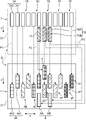
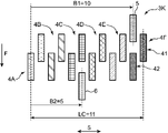
- FIG. 6 is a plan view schematically showing the head arrangement according to the first embodiment.
- FIG. 6 is also a diagram showing the arrangement of the ink head 4, the pre-processing head 5, and the post-processing head 6 (a plurality of processing heads) in the carriage 3 shown in FIG.
- the carriage 3 is supported in a cantilevered state by a guide rail 17 in the back frame 32 (engaging portion).
- the back frame 32 is arranged on the upstream side of the head support frame 31 in the transport direction F.
- the side of the head support frame 31 where the back frame 32 is arranged is the base end side 311, and the side of the head support frame 31 opposite to the base end side 311 is the tip end side 312.
- the head support frame 31 of the carriage 3 is equipped with first to sixth ink heads 4A to 4F, pretreatment heads 5, and posttreatment heads 6 for ejecting inks of six different colors. ..
- Each of the ink heads 4A to 4F of each color has two unit heads (12 in total). Although there is one pre-processing head 5, two post-processing heads 6 are provided.
- the groups of the first to sixth ink heads 4A to 4F constituting the ink head 4 are arranged so as to be aligned with the main scanning direction S in the central region of the transport direction F of the head support frame 31.
- the preprocessing head 5 is located at a substantially central portion of the carriage 3 in the main scanning direction S, on the upstream side of the ink head 4 in the transport direction F, and on the proximal end side 311 of the head support frame 31.
- the post-processing head 6 is arranged at a substantially central portion of the carriage 3 in the main scanning direction S, on the downstream side of the ink head 4 in the transport direction F, and on the tip end side 312 of the head support frame 31. Both the pre-processing head 5 and the post-processing head 6 are arranged near the central portion of the head support frame 31 in the main scanning direction S.
- the first ink head 4A includes an upstream head 4A1 and a downstream head 4A2 arranged on the downstream side of the upstream head 4A1. That is, the upstream head 4A1 and the downstream head 4A2 are arranged in the transport direction F.
- the arrangement position of the upstream head 4A1 is a position closer to the proximal end side 311 in the central region of the head support frame 31.
- the arrangement position of the downstream head 4A2 is a position closer to the tip end side 312 in the central region of the head support frame 31.
- the downstream head 4A2 is arranged at a position shifted to one side (left side) of the main scanning direction S with respect to the upstream head 4A1 and partially overlaps with the transport direction F.
- the upstream head 4A1 and the downstream head 4A2 may be arranged at the same position in the main scanning direction S (positions linearly arranged in the transport direction F).
- the arrangement of this embodiment can reduce the size of the carriage 3 in the transport direction F.
- the second to sixth ink heads 4B to 4F also have the same upstream heads 4B1, 4C1, 4D1, 4E1, 4F1 and downstream heads 4B2, 4C2, 4D2, similar to the upstream heads 4A1 and downstream heads 4A2 described above. It is equipped with 4E2 and 4F2.
- the upstream heads 4A1 to 4F1 of the first to sixth ink heads 4A to 4F are arranged in a row at the same position in the transport direction F at a predetermined interval in the main scanning direction S.
- the downstream heads 4A2 to 4F2 are also arranged in a row at the same position in the transport direction F with a predetermined interval in the main scanning direction S.
- a staggered arrangement mode is formed in which a part of the downstream heads 4A2 to 4F2 is inserted between the arrangement pitches of the upstream heads 4A1 to 4F1.
- the ink head 4 has a plurality of ink head rows mounted on the carriage 3 so as to be arranged in the transport direction F.
- Each of the plurality of ink head rows includes a plurality of ink heads arranged so as to line up in the main scanning direction S and eject ink for image formation.
- the plurality of ink head rows have a first ink head row 41 and a second ink head row 42.
- the ink heads included in the first ink head row 41 are upstream heads 4A1, 4B1, 4C1, 4D1, 4E1, and 4F1.
- the ink heads included in the second ink head row 42 are downstream heads 4A2, 4B2, 4C2, 4D2, 4E2, and 4F2.
- the pretreatment head 5 is arranged so that a part thereof is inserted between a pair of adjacent ink heads in the main scanning direction S. Specifically, the positional relationship is such that the downstream portion of the preprocessing head 5 is inserted between the upstream head 4C1 of the third ink head 4C and the upstream head 4D1 of the fourth ink head 4D.
- the post-processing head 6 includes a first post-processing head 6A and a second post-processing head 6B arranged side by side in the main scanning direction S.
- FIG. 6 shows an example in which the first and second post-processing heads 6A and 6B are arranged at the same position in the transport direction F at a predetermined interval in the main scanning direction S.
- the first post-processing head 6A is arranged so that an upstream portion thereof is inserted between the downstream head 4C2 of the third ink head 4C and the downstream head 4D2 of the fourth ink head 4D.
- the second post-processing head 6B is arranged between the downstream head 4D2 and the downstream head 4E2 so that the upstream portion thereof is inserted, and is arranged at the same position as the upstream head 4D1 in the main scanning direction S. ..
- the first and second post-processing heads 6A and 6B are arranged so as to have an overlapping region fa in the transport direction F with the downstream heads 4C2, 4D2, and 4E2.
- each head In the transport direction F, the width of each head is larger than the print width Pw and the arrangement range of the ejection nozzles. Therefore, each head is arranged to have an overlapping area fa so as not to be vacant between the print range Pw of the heads in each row and the print range Pw of the heads in the adjacent row.
- the distance between adjacent heads in the main scanning direction S (the distance between the centers of the heads) is the same.
- the distance between adjacent heads (distance between the centers of each head) in the transport direction F is the same.
- the pre-processing head 5 and the post-processing head 6 are arranged within the range of the arrangement width H in the main scanning direction S of the ink head 4.
- the ink head 4 has an arrangement width H between the downstream head 4A2 of the first ink head 4A and the upstream head 4F1 of the sixth ink head 4F in the main scanning direction S.
- the pre-processing head 5 is arranged within the range of the arrangement width H on the upstream side of the ink head 4
- the post-processing head 6 is arranged within the range of the arrangement width H on the downstream side of the ink head 4.
- the pre-processing head 5 and the post-processing head 6 are located substantially at the center of the array of all heads in the main scanning direction S.
- the head arrangement according to the first embodiment described above it is possible to increase the required amount of ink and processing liquid while reducing the size of the carriage 3. That is, the pre-processing head 5 and the post-processing head 6 are arranged at positions different from those of the ink head 4 in the transport direction F.
- the ink heads 4A to 4F capable of increasing the required ink ejection amount are arranged in the main scanning direction S, and the printing processing can be performed in both the outward main scanning and the inbound main scanning, while the heads 4 to 4F are described above.
- the width in the main scanning direction of the carriage required for mounting the 6 can be shortened.
- the post-processing head 6 is composed of a plurality of first and second post-processing heads 6A and 6B, which are arranged side by side in the main scanning direction S. Therefore, even if the discharge amount of the post-treatment liquid is insufficient with the single head, the required amount can be discharged by arranging the plurality of post-treatment heads 6A and 6B.
- the first to sixth ink heads 4A to 4F are the upstream heads 4A1 to 4F1 (first ink head row 41) and the downstream side arranged in the transport direction F (the direction intersecting the arrangement direction of the plurality of processing heads), respectively.
- the heads 4A2 to 4F2 (second ink head row 42) are provided. Therefore, even if the number of ink heads 4 is increased in order to increase the ejection amount of the ink of each color or to increase the number of colors, it is difficult to increase the width of the carriage 3 in the main scanning direction.
- the pre-processing head 5 and the post-processing head 6 are arranged within the range of the arrangement width H in the main scanning direction S of the first to sixth ink heads 4A to 4F. Therefore, even when the pre-processing head 5 and the post-processing head 6 are mounted on the carriage 3 in addition to the ink head 4, it is not necessary to expand the width in the main scanning direction of the carriage 3. That is, it is difficult to increase the width of the carriage 3 in the main scanning direction.
- the pre-processing head 5 and the post-processing head 6 are arranged so that a part thereof is inserted between the arrangement pitches of the first to sixth ink heads 4A to 4F. Focusing on the first post-processing head 6A, a part of the first post-processing head 6A is inserted between the pair of downstream heads 4C2 and 4D2. With such a staggered arrangement, the ink heads 4 and the processing heads 5 and 6 arranged at different positions in the transport direction F can be arranged at high density in the transport direction F. Therefore, the width of the carriage 3 in the transport direction F can be reduced.
- one pre-processing head 5 is arranged on the upstream side of the ink head 4 and two post-processing heads 6A and 6B are arranged on the downstream side in the transport direction F, respectively. That is, it is possible to provide an all-in-one type inkjet printer 1 in which three types of heads, a head for discharging a pretreatment liquid, an ink, and a posttreatment liquid, are mounted on one carriage 3. Further, since the pretreatment head 5, the ink head 4, and the posttreatment head 6 are sequentially arranged in the transport direction F, the pretreatment liquid, the ink, and the posttreatment liquid are desirable in both the outward main scan and the return main scan. It can be ejected in the order of landing.
- the carriage 3 has a back frame 32 (engaging portion) held in a cantilevered state by a guide rail 17 (holding member) (FIG. 1).
- a back frame 32 engaging portion held in a cantilevered state by a guide rail 17 (holding member) (FIG. 1).
- the pre-processing head 5 is on the proximal end side 311 (closer to the engaging portion) of the head support frame 31, and the post-processing head 6 is on the distal end side 312 (far from the engaging portion). It is arranged on each side). Unlike the base end side 311 close to the back frame 32 fixed to the timing belt 16, it is assumed that the position accuracy is lowered at the tip end side 312 which is a free end. However, the tip side 312 is equipped with a post-processing head 6 which is not required to have a relatively high degree of severity in ejection accuracy.
- the post-treatment liquid coats the ink image printed on the work W, even if the landing position shift occurs, the image quality is better than the same degree of landing position shift in the pretreatment liquid.
- the relative impact given can be reduced. Therefore, even when the carriage 3 supported by the cantilever is used, it is possible to prevent the quality of the image from being deteriorated.
- the pretreatment head 5 for discharging the pretreatment liquid and the post-processing head 6 for discharging the post-treatment liquid are mounted on the carriage 3, respectively, and the carriage 3 reciprocates in the main scanning direction.
- the pretreatment liquid, the ink, and the posttreatment liquid are ejected to the work W in order, depending on the image position in the main scanning direction S, the time from the landing of the pretreatment liquid to the landing of the ink and the landing of the ink may occur.
- the time until the post-treatment liquid lands varies, and as a result, the image quality tends to vary on the work W.
- the color development becomes deeper as the time from the pretreatment liquid landing to the ink landing becomes longer.
- a post-treatment liquid that enhances fastness is used, the color development becomes deeper as the time from the ink landing to the post-treatment liquid landing becomes longer.
- the longer the time from the landing of the pretreatment liquid to the landing of the post-treatment liquid the darker the color development.
- the time from the landing of the pretreatment liquid to the first landing ink after the landing has a relatively large effect on the color density.
- the time from the landing of the post-treatment liquid to the last landing ink before the landing has a relatively large influence on the color development density.
- the present disclosers appropriately set the arrangement of the pre-processing head 5 and the post-processing head 6 on the carriage 3 in order to solve the above-mentioned problems, so that even between different image positions in the main scanning direction S. It was newly found that it is possible to reduce the variation in the time from the landing of the pretreatment liquid to the landing of the ink and the variation in the time from the landing of the ink to the landing of the post-treatment liquid.
- the concept of head arrangement and an example of the arrangement (Example) based on such a new point of view will be described below.
- FIG. 7 is a schematic diagram for explaining the landing time of the pretreatment liquid, the ink, and the posttreatment liquid at the point P on the work W.
- the print area 12 is arranged in the central portion, and the maintenance area 13 and the folded area 14 are arranged on both the left and right sides thereof.
- the carriage 3 moves between the maintenance area 13 and the folding area 14 along the main scanning direction S, so that the ink head 4, the pretreatment head 5, and the post-processing head 6 ink the work W.
- the pretreatment liquid and the posttreatment liquid are discharged respectively.
- the carriage 3 is shown in both the maintenance area 13 and the folding area 14 for the sake of explanation.
- the ink head 4 has a plurality of ink head rows, and the work W is intermittently fed at one head pitch (interval pitch between adjacent heads in the transport direction F) while printing is performed. I will explain.
- one end of a plurality of ink heads and processing heads (pre-processing head 5 and post-processing head 6) included in the plurality of ink head rows 41 and 42, which are arranged on the most one end side in the main scanning direction S, is used.
- the side head, the head arranged on the farthest end side is the other end side head, the distance in the main scanning direction S from the one end side head to the other end side head is LC, and the main from the one end side head to the pretreatment head 5.
- the distance in the scanning direction S is B1, the distance in the main scanning direction S from the one end side head to the predetermined ink head (upstream head 4D1 of the fourth ink head 4D in FIG.
- the distance to the processing head 6 in the main scanning direction S is defined as B2.
- one end side head is a downstream side head 4A2 of the first ink head 4A
- the other end side head is an upstream side head 4F1 of the sixth ink head 4F.
- the distances LC, K, B1 and B2 may be set with reference to a part of each head, but in the following description, each of the above distances is set with reference to the center of the main scanning direction S of each head. Will be described. Further, the one end side head and the other end side head may be reversed.
- the center of the main scanning direction S of the head is basically a virtual line orthogonal to the main scanning direction S, which bisects the area of the planar shape with respect to the planar shape when the head is viewed from above. It is the position of the virtual line in the main scanning direction S when the above is considered.
- the area of the convex polygon is bisected with respect to the convex polygon having the smallest area among the convex polygons including all the ejection nozzles of the head.
- the position of the virtual line in the main scanning direction S may be the center of the main scanning direction S of the head.
- the timing at which each liquid lands on the point P on the work W in the print area 12 will be described. Since the moving speed of the carriage 3 is constant, the distance will be used in the following description.
- the actual timing (time) can be calculated by dividing each distance by the moving speed of the carriage 3. It is assumed that the point P is located at a distance A from the end of the print area 12 on the maintenance area 13 side.
- the liquid is discharged from the center of the main scanning direction S of the head.
- the nozzles provided in each head are actually spread and distributed in the main scanning direction S, the spread also affects the landing timing.
- the difference in the position of the nozzles in the main scanning direction S in one head is often smaller than the difference in the position of the nozzles in the main scanning direction S in different heads, it is the center of the head in the main scanning direction S. It is possible to estimate the effect of the arrangement of the heads by considering that the nozzles are discharged from the head.
- the timing of discharge and the timing of landing are explained as if they were at the same time.
- the discharge is performed earlier than the landing timing by the amount of flight time during which the liquid flies from the head to the work W so that the liquid lands at a predetermined position at a predetermined timing.
- the one-way movement distance of the carriage 3 (the distance traveled from the maintenance area 13 to the folding area 14) is the minimum distance LP + LC required for printing, and the carriage 3 is arranged in the maintenance area 13 as an initial position.
- the timing T1 at which the pretreatment liquid discharged from the pretreatment head 5 lands on the point P is set. It can be expressed by the following formula A in terms of distance.
- the timing T2 at which the red ink (also referred to as the first ink or the first ink) lands on the point P from the upstream head 4D1 of the fourth ink head 4D can be expressed by the following formula B.
- Equation B (LP + LC) + (LP-A) + (LC-K) (Equation B)
- the inside of the first parenthesis of the above equation B corresponds to the time for the carriage 3 to move from the maintenance area 13 to the folding area 14 in the first movement operation, and the inside of the second parenthesis is the tip of the carriage 3 in the second movement operation.
- the third parenthesis corresponds to the time until the predetermined ink head reaches the point P by further moving the carriage 3.
- the carriage 3 may first move from the folded area 14, that is, may move to the right as the first movement operation during printing on the work W.
- the time ⁇ T from the landing of the pretreatment liquid to the landing of the first (first) red ink can be expressed by the following formula D.
- ⁇ T 2A-LP- (LC- (B1 + K)) + (LP + LC) (Equation D)
- the red ink (also referred to as the second ink or the last ink) ejected by the downstream head 4D2 of the fourth ink head 4D lands on the point P, and then the post-treatment liquid is discharged.
- the time before landing ⁇ T will be described.
- the first movement operation is a leftward movement from the maintenance area 13 to the turn-back area 14
- the time ⁇ T from the landing of the red ink of the downstream head 4D2 to the landing of the post-treatment liquid at the point P is , Can be expressed by the following equation H.
- ⁇ T LP-2A + (LC- (K + B2)) + (LP + LC) (Equation H)
- the second ink is landed after the first ink landing represented by the formula C.
- the ink head rows of the ink heads 4 are an odd number of rows along the transport direction F, the second ink is landed after the first ink landing represented by the formula D.
- the second ink is landed after the first ink landing represented by the formula D.
- the ink head rows of the ink heads 4 are an odd number of rows along the transport direction F, the second ink is landed after the first ink landing represented by the formula C.
- At least one preprocessing head 5 is arranged so as to satisfy the formula 1.
- At least one post-processing head 6 is arranged so as to satisfy the formula 2.
- the time variation from the ink landing to the post-treatment liquid landing can be reduced, and in addition, from the other post-processing heads 6. Since the post-treatment liquid can be further discharged, the amount of the post-treatment liquid that can be discharged can be increased.
- the carriage 3 equipped with both the pre-processing head 5 and the post-processing head 6 has been described.
- the processing head mounted on the carriage 3 is only the pre-processing head 5.
- only the post-processing head 6 may be used.
- the equation 1 is satisfied, the variation in the time from the landing of the pretreatment liquid to the landing of the ink can be reduced.
- the equation 2 is satisfied, the variation in the time from the landing of the ink to the landing of the pretreatment liquid can be reduced.
- the range of the ⁇ T differs between the first to sixth ink heads 4A to 4F. That is, the range of ⁇ T depends on the magnitude of K. In the example shown in FIG. 7, when B1> LC / 2, the larger the value of K, the larger the variation range of ⁇ T. In other words, among the ink heads 4, the black ink on the sixth ink head 4F has the largest time variation.
- the time variation from the landing of the pretreatment liquid to the landing of the first black ink is large, the time variation from the landing of the second black ink to the landing of the post-treatment liquid is also large.
- the black color image has a remarkable variation in image quality as compared with the image of other colors, and the image with the naked eye is likely to be affected. Therefore, in the sixth ink head 4F that ejects black ink having a large K value, it is desirable to reduce the time variation from the second landing of the black ink to the landing of the post-treatment liquid. Specifically, it is desirable to arrange the post-processing head 6 so that B2 becomes small.
- the present disclosers mount a plurality of ink head rows including ink heads that eject ink of the same color on the carriage 3, and the ink head 4 is mounted.
- the inks are arranged together in the main scanning direction for each color, the time variation from the landing of the pretreatment liquid to the landing of the first ink is large in the ink of a predetermined color, and further, the second ink It is effective to set the absolute value of (B1 + B2-LC) / LC small in order to prevent a large time variation from the impact of the ink to the impact of the post-treatment liquid, and the following equation 3 is satisfied.
- distance B1 6 in the main scanning direction S from the downstream head 4A2 to the preprocessing head 5, main scanning direction S from the downstream head 4A2 to each post-processing head 6.
- the distance B2 5 or 7 in.
- / LC 0.045, which satisfies the above equation 1.
- / LC 0.045 or 0.136, both of which satisfy the above formula 2.
- the time variation from the landing of the pretreatment liquid to the landing of the ink ejected by the first ink head row 41 and the time variation from the landing of the ink ejected by the second ink head row 42 to the landing of the post-treatment liquid are small. can.
- the pretreatment liquid, the ink, and the post-treatment liquid can be stably and sequentially landed on the work W, and the image quality is less likely to vary on the work W.
- 0 or 0.18, both of which satisfy the above formulas 3 and 4.
- the post-processing head 6 of the first post-processing head 6A and the second post-processing head 6B of the post-processing head 6 is arranged at a position that does not satisfy the above equations 1 to 4. However, it is most desirable that any of the post-processing heads 6 satisfies the above equations 1 to 4 as shown in FIG.
- FIG. 8 is a plan view of the carriage 3A showing the head arrangement according to the second embodiment.
- the ink head 4 has the first ink head row 41 and the second ink head row 42, and the pre-processing head 5 and the post-processing head 6 are substantially centered in the main scanning direction S of the array of all heads. It is located in the department.
- / LC 0.045, which satisfies the above equation 1.
- / LC 0.045, which satisfies the above equation 2.
- FIG. 9 is a plan view of the carriage 3B showing the head arrangement according to the third embodiment.
- the ink head row is one row.
- the pre-processing head 5 and the post-processing head 6 are located substantially at the center of the array of all heads in the main scanning direction S.
- / LC 0, which satisfies the above equation 1.
- / LC 0, which satisfies the above equation 2.
- 0, which satisfies the above equations 3 and 4. Therefore, the same effect as that of Examples 1 and 2 can be obtained.
- FIG. 10 is a plan view schematically showing the carriage 3D provided with the head arrangement according to the fourth embodiment.
- Example 4 differs from Example 1 in that the number of each unit head is increased. That is, the ink heads 4 are the same as those of the first embodiment in that they include the first to sixth ink heads 4A to 4F, each of which ejects inks of six different colors, but the ink heads 4A to 4F of each color are provided. Each has 3 unit heads (18 in total). In other words, the ink head 4 has three rows (odd rows) of ink head rows including a first ink head row 41, a second ink head row 42, and a third ink head row 43.
- the pre-processing head 5 arranged on the upstream side of the transport direction F of the ink head 4 has two unit heads, and the post-processing head 6 arranged on the downstream side has three unit heads.
- the point that the pre-processing head 5 and the post-processing head 6 are arranged within the range of the arrangement width of the main scanning direction S of the ink head 4 is the same as that of the first embodiment.
- the first ink head 4A includes an upstream head 4AA, a central head 4AB, and a downstream head 4AC as the unit head.
- the upstream head 4AA is arranged on the most upstream side of the first ink head 4A in the transport direction F of the carriage 3A.
- the downstream head 4AC is arranged on the downstream side of the upstream head 4AA at the same position as the upstream head 4AA in the main scanning direction S.
- the central head 4AB is a position shifted to the right in the main scanning direction S with respect to the upstream head 4AA and the downstream head 4AC, and is downstream from the upstream head 4AA and from the downstream head 4AC in the transport direction F. It is located on the upstream side.
- the central head 4AB is arranged at a position where a part of the central head 4AB overlaps with the upstream head 4AA and the downstream head 4AC in the transport direction F, respectively.
- the second to sixth ink heads 4B to 4F also have the same upstream head 4BA, central head 4AB and downstream head 4AC as the upstream head 4BA, 4CA, 4DA, 4EA, 4FA, and the central head 4BB, 4CB. It is equipped with 4DB, 4EB, 4FB, and downstream heads 4BC, 4CC, 4DC, 4EC, and 4FC.
- the upstream heads 4AA to 4FA, the central heads 4BB to 4FB, and the downstream heads 4BC to 4FC of the first to sixth ink heads 4A to 4F are located at the same position in the transport direction F and at predetermined intervals in the main scanning direction S. They are lined up in a row. Further, the ink heads 4 are arranged together in the main scanning direction for each color.
- the pre-processing head 5 includes a first pre-processing head 5A and a second pre-processing head 5B arranged so as to be arranged at the same position in the transport direction F and at intervals in the main scanning direction S.
- the first pretreatment head 5A is arranged so that a part of the downstream side thereof is inserted between the upstream head 4CA of the third ink head 4C and the upstream head 4DA of the fourth ink head 4D.
- the second pretreatment head 5B is arranged so that a part of the downstream side thereof is inserted between the upstream head 4DA of the fourth ink head 4D and the upstream head 4EA of the fifth ink head 4E.
- the post-processing head 6 includes a first post-processing head 6A, a second post-processing head 6B, and a third post-processing head 6C arranged so as to be arranged at the same position in the transport direction F and at intervals in the main scanning direction S. include.
- the first post-processing head 6A is arranged so that a part of the upstream side thereof is inserted between the downstream head 4BC of the second ink head 4B and the downstream head 4CC of the third ink head 4C.
- the second post-processing head 6B is arranged so that a part of the upstream side thereof is inserted between the downstream head 4CC of the third ink head 4C and the downstream head 4DC of the fourth ink head 4D.
- the third post-processing head 6C is arranged so that a part of the upstream side thereof is inserted between the downstream head 4DC of the fourth ink head 4D and the downstream head 4EC of the fifth ink head 4E.
- the same advantages as those of the first embodiment can be enjoyed. That is, it is possible to increase the required amount of ink and processing liquid while reducing the size of the carriage 3D.
- both the pretreatment head 5 and the posttreatment head 6 are provided with a plurality of unit heads, a sufficient discharge amount of the pretreatment liquid and the posttreatment liquid can be sufficiently increased.
- the first to sixth ink heads 4A to 4F also have unit heads arranged in three rows, the amount of ink ejected can be sufficiently increased.
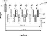
- FIG. 11 is a plan view schematically showing the carriage 3E having the head arrangement according to the fifth embodiment.
- the pre-processing head 5 and the post-processing head 6 are arranged in the central region HC having the arrangement width H.
- the fifth embodiment differs from the first embodiment in the arrangement of the ink head 4 as described later.
- the head support frame 31 of the carriage 3E is equipped with first to sixth ink heads 4A to 4F, pretreatment heads 5, and posttreatment heads 6 for ejecting inks of six different colors.
- the first to sixth ink heads 4A to 4F include unit heads arranged in two rows as in the first embodiment. However, the shift direction of the downstream heads of the ink heads 4A to 4F is opposite to that of the first embodiment so that the downstream head 4A2 is arranged on the right side of the upstream head 4A1 in the first ink head 4A. ..
- the pre-processing head 5 is provided with one
- the post-processing head 6 is provided with two first and second post-processing heads 6A and 6B, respectively.
- the pre-processing head 5 and the post-processing head 6 are arranged in the central region HC of the arrangement width H in the main scanning directions S of the first to sixth ink heads 4A to 4F.
- the point that the pretreatment head 5 is arranged on the upstream side and the post-processing head 6 on the downstream side of the array of the first to sixth ink heads 4A to 4F in the transport direction F is the same as that of the above-mentioned Example 1.
- the pretreatment head 5 is arranged at the same position in the main scanning direction S as the downstream head 4C2 of the third ink head 4C, and is arranged on the upstream side in the transport direction F.
- the pretreatment head 5 is arranged so that a part of the downstream side thereof is inserted between the upstream heads 4C1 and 4D1 of the third and fourth ink heads 4C and 4D.
- the first and second post-processing heads 6A and 6B are arranged at the same position in the transport direction F with a predetermined interval in the main scanning direction S.
- the first post-processing head 6A is arranged so that an upstream portion thereof is inserted between the downstream head 4B2 of the second ink head 4B and the downstream head 4C2 of the third ink head 4C.
- the second post-processing head 6B is arranged so that the upstream side portion thereof is inserted between the downstream side head 4C2 and the downstream side head 4D2 of the fourth ink head 4D.
- the distance LC 11 in the main scanning direction S from the upstream head 4A1 of the first ink head 4A to the downstream head of the sixth ink head 4F, and the pretreatment from the upstream head 4A1.
- / LC 0.045, which satisfies the above equation 1.
- / LC 0.136 or 0.045, both of which satisfy the above formula 2.
- the time variation from the landing of the pretreatment liquid to the landing of the ink ejected by the first ink head row 41 and the time variation from the landing of the ink ejected by the second ink head row 42 to the landing of the post-treatment liquid are small. can.
- the pretreatment liquid, the ink, and the post-treatment liquid can be stably and sequentially landed on the work W, and the image quality is less likely to vary on the work W.
- 0.18 or 0, both of which satisfy the above equations 3 and 4.
- the pre-processing head 5 and the post-processing head 6 are not only arranged in the central region HC of the arrangement width H, but also the arrangement center of the pre-processing head 5 and the arrangement of the first and second post-processing heads 6A and 6B.
- the center is arranged so as to coincide with each other in the main scanning direction S.
- the center of the pre-processing head 5 in the main scanning direction S is the arrangement center C1.
- the intermediate point between the first post-processing head 6A and the second post-processing head 6B is the arrangement center C2.
- the pre-processing head 5 and the post-processing head 6 are arranged on the head support frame 31 so that the arrangement center C1 and the arrangement center C2 are at the same position in the main scanning direction S.
- the carriage 3 repeats the outbound main scan and the inbound main scan to sequentially land the pretreatment liquid, the ink, and the posttreatment liquid on the work W.
- the head arrangement of the fifth embodiment by adopting the head arrangement of the fifth embodiment, the time variation from the landing of the pretreatment liquid to the landing of the ink on the work W at each main scanning position can be obtained.
- the variation in the time from the impact of the ink to the impact of the post-treatment liquid can be particularly reduced.
- the central region HC is preferably a region located in the center of the range of the placement width H and having a width of half of the placement width H, and further preferably a one-third region.
- the fact that the processing heads are arranged in the central region HC means that the arrangement center of the processing heads is arranged in the central region HC and more than half of the arrangement centers of the processing heads are arranged in the central region HC. do. Further, all of the arrangement centers of the processing heads may be arranged in the central region HC.
- Example 6 In Example 6 and the subsequent Example 7, the head arrangement of the processing heads 5 and 6 with heat generation countermeasures is illustrated.
- a head that discharges a liquid by a jet method generates heat because it pressurizes the liquid using electricity.
- the ink head 4 performs a ejection operation only when a necessary color dot is formed.
- the pretreatment head 5 and the posttreatment head 6 require the discharge operation of the pretreatment liquid and the posttreatment liquid corresponding to the dots of all colors. Therefore, the pre-processing head 5 and the post-processing head 6 are more likely to have a higher temperature than each of the ink heads 4. Therefore, it is desirable to arrange the heads assuming that the pre-processing head 5 and the post-processing head 6 are heated in temperature.
- FIG. 12 is a plan view schematically showing the carriage 3F provided with the head arrangement according to the sixth embodiment.
- the back frame 32 engaging portion
- the head support frame 31 includes ink heads 4 provided with first to sixth ink heads 4A to 4F, one pretreatment head 5, and post-processing heads including first and second post-processing heads 6A and 6B. 6 and are installed. Since these head arrangements are the same as those of the first embodiment shown in FIG. 6, the description thereof is omitted here.
- the pre-processing head 5 is composed of one unit head
- the post-processing head 6 is composed of two unit heads (first and second post-processing heads 6A and 6B), respectively.
- the pre-processing head 5 having a small number of unit heads is arranged on the proximal end side 311 of the head support frame 31.
- the post-processing head 6 having a large number of unit heads is arranged on the tip side 312. In other words, the upstream end edge of the head support frame 31 in the transport direction F is the side held by the guide rail 17.
- the processing heads 5 and 6 generate heat due to the ejection operation.
- the pretreatment head 5 which has been heated to a high temperature dissipates heat ha.
- the head support frame 31 of the carriage 3F is heated by this heat ha, and the head support frame 31 and its holding structure, the back frame 32, and the fixing brackets between the back frame 32 and the timing belt 16 are thermally deformed. Can be. This thermal deformation may affect the landing accuracy of the ink ejected from the ink head 4 in the carriage 3F held in the cantilever state.
- the preprocessing head 5 having a small number of unit heads is arranged on the base end side 311 which is the cantilever holding side of the head support frame 31.
- the influence of thermal deformation (decrease in landing accuracy) can be reduced.
- the post-processing head 6 having a large number of unit heads is arranged on the base end side 311, the back frame 32 receives heat ha from the two unit heads, becomes higher in temperature, and is easily deformed by heat.
- the pre-processing head 5 is arranged at a position excluding the end of the main scanning direction S in the head array HA (head arrangement area) of the ink head 4 and the processing heads 5 and 6. .
- the pre-processing head 5 which is a processing head is a head arranged on the side closest to the back frame 32 (engaging portion).
- Such a pretreatment head 5 is arranged at a position other than the arrangement end 313 which is the end of the head array HA.
- the arrangement end 313 of the head array in the main scanning direction S will be the main scanning direction S of the carriage 3F (head support frame 31) if a head is arranged there. It will be the head closest to the corner of. Since the vicinity of the arrangement end 313 is also the vicinity of the back frame 32 that is cantilevered, if thermal deformation occurs in the vicinity thereof, distortion or misalignment in the height direction or the horizontal direction of the head support frame 31 can be induced. This lowers the landing position accuracy of the heads 4, 5 and 6 mounted on the carriage 3F. Therefore, by not arranging the processing heads (pre-processing head 5 and post-processing head 6) that increase the temperature in the region of the arrangement end 313, the above-mentioned thermal deformation problem can be less likely to occur.
- the row of heads 4 arranged on the engaging portion side is shown in FIG. It has a staggered arrangement that is offset to the right.
- the pre-processing head 5 which is a processing head having a small number of heads is arranged on the engaging portion side, and the pre-processing head 5 is arranged at the center of the arrangement position in which the arrangement is staggered. By arranging in this way, the head can be arranged so that the processing head is not arranged at the arrangement end 313.
- a preferred ink head arrangement example will be further described with reference to the head arrangement of the carriage 3F shown in FIG.
- a part of the pretreatment head 5 that is heated to a high temperature is arranged so as to be adjacent to the ink head 4.
- the pretreatment head 5 is adjacent to the upstream heads 4C1 and 4D1 of the third and fourth ink heads 4C and 4D in the main scanning direction S, and the downstream head 4D2 of the fourth ink head 4D in the transport direction F. Is adjacent to.
- the first post-processing head 6A is adjacent to the downstream heads 4C2 and 4D2 of the third and fourth ink heads 4C and 4D in the main scanning direction S, and is adjacent to the upstream head 4C1 in the transport direction F.
- the second post-processing head 6B is adjacent to the downstream heads 4D2 and 4E2 of the fourth and fifth ink heads 4D and 4E in the main scanning direction S, and is adjacent to the upstream head 4D1 in the transport direction F.
- the pre-processing head 5 and the post-processing head 6 are not adjacent to the first, second, and sixth ink heads 4A, 4B, and 4F.
- the third, fourth, and fifth ink heads 4C, 4D, and 4E (first ink heads that eject the first color ink) that eject yellow, red, and blue ink, respectively, are used.
- Pretreatment head 5 and post-processing heads 4A, 4B, 4F (second ink head that ejects second color ink), respectively, which ejects orange, green, and black ink.
- the number of unit heads adjacent to the processing head 6 is large. That is, the third, fourth, and fifth ink heads 4C, 4D, and 4E are ink heads that are more likely to have a higher temperature than the other ink heads 4A, 4B, and 4F.
- the ink ejection characteristics (ejection amount, etc.) from the ink head also change.
- the viscosity change characteristics depending on the temperature differ depending on the type of ink. Therefore, in the case of this embodiment, the inks to be ejected from the third, fourth, and fifth ink heads 4C, 4D, and 4E, which tend to have high temperatures, are ejected from the first, second, and sixth ink heads 4A, 4B, and 4F. Ink with a smaller change in viscosity due to temperature is ejected than with ink.
- the number of unit heads of the processing heads adjacent to the ink head 4 for each ink may be evaluated by the one having the largest number of unit heads of the adjacent processing heads among the ink heads 4 for ejecting a certain ink. ..
- the maximum number of unit heads of adjacent processing heads is 0.
- the maximum number of unit heads of adjacent processing heads is 2
- the maximum number of unit heads of adjacent processing heads is 3.
- the maximum number of unit heads of adjacent processing heads is 1.
- the number of unit heads of the processing heads adjacent to the ink head 4 for each ink may be evaluated by averaging the number of unit heads of the adjacent processing heads in the ink head 4 for ejecting a certain ink.
- the average number of unit heads of adjacent processing heads is 0.
- the average number of unit heads of adjacent processing heads is 1.5
- the average number of unit heads of adjacent processing heads is 2.5
- the average number of unit heads of adjacent processing heads is 0.5.
- the ink head 4 for ejecting each ink may be evaluated in the order in which the temperature tends to rise, and the ink having a small temperature change in viscosity may be ejected in the order in which the temperature tends to rise.
- Example 7 an example is shown in which measures for increasing the temperature of the pretreatment head 5 and the posttreatment head 6 are taken into consideration among a plurality of ink heads of the same color that eject ink of the same color.
- the first to sixth ink heads 4A to 4F of each color include two or three unit heads, respectively. If the difference in the number of the pre-processing heads 5 or the post-processing heads 6 adjacent to each other is large among these unit heads, there causes a problem that the ink ejection characteristics are significantly different between the unit heads. In this embodiment, an example of head arrangement that reduces the difference in the number of adjacent heads is shown.
- FIG. 13 is a plan view schematically showing the carriage 3G provided with the head arrangement according to the seventh embodiment.
- each of the two unit heads (same color ink heads) included in the first to sixth ink heads 4A to 4F is adjacent to the pre-processing head 5 or the post-processing head 6 in the main scanning direction S and the transport direction F. It has a head arrangement in which the difference between the maximum value and the minimum value of the counts is 1 or less when the number of inks to be counted is counted.
- the arrangement of the ink head 4 is the same as the head arrangement of the carriage 3F shown in FIG.
- the pretreatment head 5 includes first and second pretreatment heads 5A and 5B arranged side by side in the main scanning direction S with the upstream head 4C1 of the third ink head 4C interposed therebetween.
- the post-processing head 6 includes first and second post-processing heads 6A and 6B arranged side by side in the main scanning direction S with the downstream head 4C2 interposed therebetween.
- / LC 0.136, 0.045, which satisfies the above equation 1.
- / LC 0.227 or 0.045, both of which satisfy the above formula 2. Therefore, the time variation from the landing of the pretreatment liquid to the landing of the ink ejected by the first ink head row 41 and the time variation from the landing of the ink ejected by the second ink head row 42 to the landing of the post-treatment liquid are small. can.
- the pretreatment liquid, the ink, and the post-treatment liquid can be stably and sequentially landed on the work W, and the image quality is less likely to vary on the work W.
- B1 4
- 0.364 or 0.181, one of which does not satisfy the above formulas 3 and 4, but the other is formulas 3 and 4.
- B1 6
- 0.181 or 0, both of which satisfy the above equations 3 and 4.
- the counts of the processing heads 5 and 6 adjacent to the upstream head 4B1 and the downstream head 4B2 in the main scanning direction S and the transport direction F are 2 and 1, respectively.
- the difference is "1".
- the counts of the upstream head 4C1 and the downstream head 4C2 are all three, and the difference is "0".
- the count number of the upstream head 4D1 is one
- the count number of the downstream head 4D2 is two
- the difference is "1”.
- the remaining ink heads 4A, 4E, and 4F all have 0 counts. Therefore, the difference between the maximum value and the minimum value is 1 or less for all of the first to sixth ink heads 4A to 4F, which satisfies the above requirements.
- each of the upstream heads 4A1 to 4F1 and the downstream heads 4A2 to 4F2 of the first to sixth ink heads 4A to 4F has the maximum number of counts adjacent to the processing heads 5 and 6.
- the difference from the minimum value is 1 or less.
- FIG. 14 is a plan view schematically showing the carriage 3H having the head arrangement according to the eighth embodiment.
- the pretreatment head 5 and the posttreatment head 6 are not dispersedly arranged on the head support frame 31, but are arranged in a mass shape as much as possible so that the pretreatment liquid and the posttreatment liquid come into contact with the ink. Is shown as an example of how can be reduced.
- Example 8 illustrates a head arrangement that satisfies the following requirements (A) to (C).
- B The arrangement or arrangement center of one or more pre-processing heads 5 in the main scanning direction S and the arrangement or arrangement center of one or more post-processing heads 6 coincide with each other in the main scanning direction S, and
- C The arrangement or arrangement center of the pre-processing head 5 and the post-processing head 6 and the arrangement position of the ink head of one of the ink heads 4 coincide with each other in the main scanning direction S.
- the carriage 3H shown in FIG. 8 includes an ink head 4, a pre-processing head 5, and a post-processing head 6 having first and second post-processing heads 6A and 6B.
- the arrangement center of the pre-processing head 5 and the arrangement center of the post-processing head 6 are both the center C in the drawing, and the above requirement (B) is also satisfied. Further, the center C and the arrangement position of the downstream head 4D2 of the fourth ink head 4D match, and the above requirement (C) is also satisfied.
- the pre-processing head 5 and the post-processing head 6 can be mounted on the carriage 3H in a state of being united to some extent. This makes it possible to reduce the number of ink heads arranged at positions close to the pre-processing head 5 or the post-processing head 6 among the first to sixth ink heads 4A to 4F. Therefore, it is possible to reduce the possibility of contact between the pretreatment liquid and the posttreatment liquid and the ink on the carriage.
- FIG. 15 is a plan view showing the carriage 3I and the sub-tank arrangement provided with the head arrangement according to the ninth embodiment.
- the carriage 3I includes an ink head 4 having first to sixth ink heads 4A to 4F, one pre-processing head 5, and a post-processing head 6 having first and second post-processing heads 6A, 6B.
- These head arrangements are the same as those in FIG. 12 and others. Therefore, the head arrangement in the ninth embodiment also satisfies the relationship of the above-mentioned formulas 1 to 4, and the same effect can be obtained.
- Carriage 3I is also equipped with a sub tank 7.
- the sub-tank 7 includes ink sub-tanks 7A to 7F, a pre-treatment liquid sub-tank 71, and a post-treatment liquid sub-tank 72 (all of which are treatment liquid sub-tanks). Ink, pretreatment liquid and posttreatment liquid are supplied to these sub tanks 7 from the main tank (not shown).
- the ink sub-tanks 7A to 7F supply the ink to each of the first to sixth ink heads 4A to 4F.
- the upstream head 4A1 of the first ink head 4A is supplied with the ink of the first color from the first tank 7A1 of the ink sub-tank 7A, and the downstream head 4A2 is supplied with the ink of the first color from the second tank 7A2 via the pipeline P1.
- the second to sixth ink heads 4B to 4F also have a structure in which inks of the second color to the sixth color are supplied in the same manner.
- the arrangement order of the ink sub-tanks 7 in the main scanning direction S is the same as the arrangement order of the ink heads 4 to which the ink sub-tanks 7 supply ink in the main scanning direction S.
- Ink may be supplied from one ink sub-tank 7 to a plurality of ink heads 4 that eject ink of the same color.
- the ink heads 4 sharing the ink sub-tank 7 may be arranged at a cohesive position in the main scanning direction S.
- the ink heads 4 for ejecting the same ink are preferably arranged together in the main scanning direction S, and in the main scanning direction S, the order of arranging the ink sub-tanks 7 for each color is changed to that of the ink heads 4 of each color.
- the order of arrangement may be the same.
- the pretreatment liquid sub-tank 71 supplies the pretreatment liquid to the pretreatment head 5 via the pipeline P2.
- the post-treatment liquid sub-tank 72 includes a first tank 72A and a second tank 72B.
- the first and second tanks 72A and 72B supply the post-treatment liquid to the first and second post-treatment heads 6A and 6B via the pipeline P3, respectively.
- the ink sub-tanks 7A to 7F are mounted on the carriage 3I so as to line up in the main scanning direction S.
- the processing liquid sub-tanks 71 and 72 are arranged at different positions from the ink sub-tanks 7A to 7F in the transport direction F. Further, the treatment liquid sub-tanks 71 and 72 are arranged side by side in the main scanning direction S. Specifically, the pretreatment liquid sub-tank 71 and the first and second tanks 72A and 72B of the post-treatment liquid sub-tank 72 are in the main scanning direction S on the downstream side of the transport direction F of the ink sub-tanks 7A to 7F. They are lined up in a row. In addition, only the pretreatment liquid sub-tank 71 may be arranged on the upstream side of the ink sub-tanks 7A to 7F.
- the acceleration of the main scanning direction S acts on the liquid of the sub tank 7 mounted on the carriage 3I that reciprocates in the main scanning direction S.
- the sub tank 7 and the heads 4, 5 and 6 are connected by pipelines P1, P2 and P3, but if the sub tank 7 is widely distributed on the carriage 3I, the pipelines P1 to P3 in the main scanning direction S
- the placement range also increases. Since the inks or treatment liquids are also filled in these pipelines P1 to P3, the meniscus may be destroyed at the ejection portions of the heads 4, 5 and 6 under the influence of the acceleration.
- the ink sub-tanks 7A to 7F are mounted on the carriage 3I so as to be aligned with the main scanning direction S like the first to sixth ink heads 4A to 4F. Therefore, the ink sub-tanks 7A to 7F can be arranged in a relatively narrow range on the head support frame 31 of the carriage 3I. Similarly, the pretreatment liquid sub-tank 71 and the post-treatment liquid sub-tank 72 can also be arranged in a relatively narrow range on the head support frame 31 of the carriage 3I.
- the pretreatment liquid sub-tank 71 and the post-treatment liquid sub-tank 72 are arranged at positions different from the ink sub-tanks 7A to 7F in the transport direction F, the pre-treatment liquid sub-tank 71 and the post-treatment liquid are arranged at different positions.
- the difference in position in the main scanning direction S between the sub-tank 72 and the processing head in which each of the pre-treatment liquid sub-tank 71 and the post-treatment liquid sub-tank 72 supplies the treatment liquid can be arranged with little difference.
- the distribution range of the main scanning direction S of the pretreatment liquid connected to the pretreatment liquid sub-tank 71, the pipeline P and the pretreatment head 5 can be reduced, and the influence of the acceleration can be reduced.
- the distribution range of the connected post-treatment liquids in the main scanning direction S can be reduced, and the influence of the acceleration can be reduced.
- the ink sub-tanks 7A to 7F and the ink sub-tanks 7A to 7F are arranged with a small difference in position in the main scanning direction S from the ink head 4 to which the ink is supplied.
- the distribution range of the connected inks in the main scanning direction S can be reduced, and the influence of the acceleration can be reduced.
- FIG. 16 is a plan view of the carriage 3J showing the head arrangement according to the tenth embodiment.
- the ink head 4 has a first ink head row 41 and a second ink head row 42.
- the post-processing head 6 is located substantially at the center of the array of all heads in the main scanning direction S, while the pre-processing head 5 is located at one end of the array (left end in FIG. 16). is doing.
- the downstream side head and the pretreatment head 5 of the first ink head 4A correspond to the one end side head.
- FIG. 17 is a plan view of the carriage 3K showing the head arrangement according to the eleventh embodiment.
- the ink head 4 has a first ink head row 41 and a second ink head row 42.
- the post-processing head 6 is located substantially at the center of the array of all heads in the main scanning direction S, while the pre-processing head 5 is located at the other end of the array (the right end in FIG. 17). positioned.
- the head on the downstream side of the first ink head 4A corresponds to the head on the one end side.
- such a head arrangement also has a margin for the demand for time variation from the landing of the pretreatment liquid to the landing of the ink ejected by the first ink head row 41 due to the function of the pretreatment liquid.
- the arrangement of the pre-processing head 5 may satisfy the formula 1, while the arrangement of the post-processing head 6 may not satisfy the formula 2.
- the function of the post-treatment liquid due to the function of the post-treatment liquid, there is a lenient requirement for a time variation from the landing of the ink ejected by the second ink head row 42 to the landing of the post-treatment liquid, while the first from the landing of the pre-treatment liquid. This is suitable when the time variation until the ink ejected by the ink head row 41 is landed should be reduced.
- the inkjet printer 1 described in each embodiment is mounted on the carriage 3 so as to be aligned with one ink head row mounted on the carriage 3 or the transport direction F at a predetermined position in the transport direction F. It has a plurality of ink head rows, a pre-processing head, and a post-processing head.
- Each of the one or more ink head rows includes a plurality of ink heads arranged so as to line up in the main scanning direction S and eject ink for image formation.
- the pretreatment head 5 is arranged on the upstream side of the one or more ink head rows in the transport direction F, and discharges the non-color-developing pretreatment liquid.
- the post-treatment head 6 is arranged on the downstream side of the one or more ink head rows in the transport direction F, and discharges the non-color-developing post-treatment liquid.
- One inkjet recording method in the inkjet printer 1 described above is a head arranged on the most end side of the main scanning direction S among a plurality of ink heads 4 and processing heads (pre-processing head 5 and post-processing head 6).
- the head arranged on the other end side is the other end side head
- the distance from the one end side head to the other end side head in the main scanning direction S is LC
- the preprocessing head 5 is arranged so as to satisfy the relationship of
- the pretreatment liquid is discharged from the pretreatment head 5 to a predetermined recording area on the work W, and the work W is predetermined in the transport direction F.
- the ink head 4 ejects ink to the recording area where the pretreatment liquid has been ejected while feeding at the feed pitch and moving the carriage 3 in the main scanning direction S.
- an image can be efficiently formed on the work W by the inkjet printer 1 in which the pretreatment liquid and the ink ejection head are mounted on one carriage 3. Further, since the pretreatment head 5 and the ink head 4 are sequentially arranged in the transport direction F, the pretreatment liquid and the ink can be ejected to the recording medium in a desirable landing order. Further, by appropriately arranging the pretreatment head 5 so as to satisfy the equation 1, the time variation from the landing of the pretreatment liquid to the landing of the ink can be reduced. As a result, variations in image quality are less likely to occur on the work W.
- the processing head mounted on the carriage 3 may be only the preprocessing head 5. Further, in the above method, the recording may be completed without applying the post-treatment liquid, or the post-treatment liquid may be applied after the printing by the carriage 3 is completed. In the latter case, the post-treatment liquid is applied, for example, to substantially the entire surface of the work W by spraying, transfer with a roller, immersion in the post-treatment liquid, or the like.
- the post-processing head 6 is arranged so as to satisfy the relationship of
- ink is ejected from the ink head 4 to a predetermined recording area of the work W, and the work W is moved to the transport direction F at the feed pitch.
- the post-processing head 6 ejects the post-processing liquid to the recording area where the ink has been ejected while feeding and moving the carriage 3 in the main scanning direction S.
- an image can be efficiently formed on the work W by the inkjet printer 1 in which the ink and post-treatment liquid ejection heads are mounted on one carriage. Further, since the ink head 4 and the post-processing head 6 are sequentially arranged in the transport direction, the ink and the post-processing liquid can be ejected to the work W in a desirable landing order. Further, by appropriately arranging the post-processing head 6 so as to satisfy the equation 2, the time variation from the landing of the ink to the landing of the post-treatment liquid can be reduced. As a result, variations in image quality are less likely to occur on the work W.
- the processing head mounted on the carriage 3 may be only the post-processing head 6. Further, in the above method, the recording may be completed without applying the pretreatment liquid, or the pretreatment liquid may be applied before printing by the carriage 3. In the latter case, the pretreatment liquid is applied, for example, to substantially the entire surface of the work W by spraying, transfer with a roller, immersion in the pretreatment liquid, or the like.
- the pre-processing head 5 and the post-processing head 6 are arranged on the carriage 3 so as to satisfy the equations 1 and 2, and the carriage 3 is mainly scanned.
- the pretreatment liquid is discharged from the pretreatment head 5 to a predetermined recording area on the work W, and the work W is fed in the transport direction F at a predetermined feed pitch to drive the carriage 3.
- the ink is ejected from the ink head 4 to the recording area where the pretreatment liquid is ejected, and the recording area where the pretreatment liquid is ejected is discharged.
- Ink is ejected from the ink head 4, the work W is further fed in the transport direction F at the feed pitch, and the carriage 3 is moved in the main scanning direction S with respect to the recording area where the ink is ejected.
- the post-treatment liquid is discharged from the post-treatment head 6.
- the efficiency of the work W is achieved by the all-in-one inkjet printer 1 in which three types of heads, a head for discharging pretreatment liquid, ink and posttreatment liquid, are mounted on one carriage 3. It is possible to form an image. Further, since the pretreatment head 5, the ink head 4, and the posttreatment head 6 are sequentially arranged in the transport direction F, the pretreatment liquid, the ink, and the posttreatment liquid can be ejected to the recording medium in a desirable landing order.
- the time variation from the landing of the pretreatment liquid to the landing of the ink and the landing of the ink to the posttreatment liquid It is possible to reduce the time variation until the landing of the ink. As a result, variations in image quality are less likely to occur on the work W.
- FIG. 18 is a plan view of the carriage 3Z1 showing the head arrangement according to Comparative Example 1 compared with the present disclosure.
- / LC 0.409, which does not satisfy the above equation 1.
- / LC 0.682, which does not satisfy the above equation 2.
- FIG. 19 is a plan view of the carriage 3Z2 showing the head arrangement according to Comparative Example 2 compared with the present disclosure.
- / LC 0.5, which does not satisfy the above equation 1.
- / LC 0.5, which does not satisfy the above equation 2.
- the inkjet recording apparatus includes a transport unit, a carriage, one or more ink head rows, and a processing head.
- the transport unit transports the recording medium in a predetermined transport direction.
- the carriage reciprocates in the main scanning direction intersecting the transport direction.
- the one or more rows of ink heads are mounted on the carriage at predetermined positions in the transport direction.
- the processing head is mounted on the carriage and discharges a non-color-developing processing liquid.
- Each of the one or more ink head rows includes a plurality of ink heads arranged so as to be aligned in the main scanning direction to eject ink for image formation.
- the processing head includes a pretreatment head that is arranged upstream of the one or more ink head rows in the transport direction and discharges the pretreatment liquid that is the treatment liquid.
- the head arranged on the one end side in the main scanning direction is defined as the one end side head
- the head arranged on the other end side is defined as the other end side head.
- an inkjet recording device in which a pretreatment liquid and an ink ejection head are mounted on one carriage. Further, since the pretreatment head and the ink head are sequentially arranged in the transport direction, the pretreatment liquid and the ink can be ejected to the recording medium in a desirable landing order. Further, by appropriately arranging the pretreatment head so as to satisfy the equation 1, it is possible to reduce the time variation from the landing of the pretreatment liquid to the landing of the ink regardless of the moving direction of the carriage. As a result, by sequentially landing the pretreatment liquid and the ink on the recording medium, the image quality is less likely to vary on the recording medium.
- a plurality of the preprocessing heads are arranged side by side in the main scanning direction, and at least one of the plurality of preprocessing heads is arranged so as to satisfy the relationship of the above formula 1. May be good.
- all of the plurality of preprocessing heads may be arranged so as to satisfy the relationship of the above formula 1.
- the plurality of pretreatment heads are arranged so as to satisfy Equation 1, the time variation from the landing of the pretreatment liquid to the landing of the ink is further reduced, and the ink can be ejected.
- the amount of the treatment liquid can be increased.
- the processing head further includes a post-processing head that is arranged on the downstream side of the one or more ink head rows in the transport direction and ejects the post-discharge liquid that is the processing liquid.
- a plurality of the ink head rows are arranged so as to be arranged in the transport direction, and one ink head row of the plurality of ink head rows has one ink head for ejecting ink of a predetermined color.
- the other ink head row among the plurality of rows of ink heads has another ink head arranged adjacent to the one ink head and ejecting ink of the predetermined color from the one end side head.
- the pre-processing head and the post-processing head may be arranged so as to satisfy the relationship of the following equation.
- an all-in-one type inkjet recording device in which three types of heads, a head for discharging a pretreatment liquid, an ink, and a posttreatment liquid, are mounted on one carriage. Further, since the pretreatment head, the ink head, and the posttreatment head are sequentially arranged in the transport direction, the pretreatment liquid, the ink, and the posttreatment liquid can be ejected to the recording medium in a desirable landing order.
- the time from the impact of the pretreatment liquid to the impact of the ink ejected by the ink head on the upstream side in the transport direction is possible to prevent a large variation in both the variation and the time variation from the impact of the ink ejected by the ink head on the downstream side in the transport direction to the impact of the post-treatment liquid.
- the inkjet recording apparatus includes a transport unit that transports a recording medium in a predetermined transport direction, a carriage that reciprocates in a main scanning direction that intersects the transport direction, and a predetermined transport direction.
- Each of the one or more ink head rows comprising one or more ink head rows mounted on the carriage and a processing head mounted on the carriage and ejecting a non-color-developing treatment liquid at the position of Includes a plurality of ink heads, each of which ejects image-forming ink, arranged so as to line up in the main scanning direction, as the processing head for the one or more ink head rows in the transport direction.
- a post-processing head for discharging the post-processing liquid, which is the processing liquid, is provided on the downstream side, and one end of the plurality of ink heads and the head arranged on the most one end side in the main scanning direction among the plurality of ink heads and the processing heads.
- the side head, the head arranged on the farthest end side is the other end side head, the distance from the one end side head to the other end side head in the main scanning direction is LC, and the distance from the one end side head to the post-processing head.
- an inkjet recording device in which an ink and post-treatment liquid ejection head is mounted on one carriage. Further, since the ink head and the post-processing head are sequentially arranged in the transport direction, the ink and the post-processing liquid can be ejected to the recording medium in a desirable landing order. Further, by appropriately arranging the post-processing heads so as to satisfy Equation 2, it is possible to reduce the time variation from the landing of the ink to the landing of the post-treatment liquid regardless of the moving direction of the carriage. As a result, variations in image quality are less likely to occur on the recording medium.
- a plurality of the post-processing heads are arranged side by side in the main scanning direction, and at least one of the plurality of post-processing heads is arranged so as to satisfy the relationship of the formula 2. You may.
- all of the plurality of post-processing heads may be arranged so as to satisfy the relationship of the above equation 2.
- the plurality of post-processing heads are arranged so as to satisfy Equation 2, the time variation from the impact of the ink to the impact of the post-treatment liquid is further reduced, and the ink can be ejected.
- the amount of the treatment liquid can be increased.
- the processing head further includes a pre-processing head that is arranged upstream of the one or more ink head rows in the transport direction and ejects the pre-discharged liquid which is the processing liquid.
- a plurality of the ink head rows are arranged so as to be arranged in the transport direction, and one ink head row of the plurality of ink head rows has one ink head for ejecting ink of a predetermined color.
- the other ink head row among the plurality of rows of ink heads has another ink head arranged adjacent to the one ink head and ejecting ink of the predetermined color from the one end side head.
- the pre-processing head and the post-processing head may be arranged so as to satisfy the relationship of the following equation.
- the processing head further includes a pre-processing head that is arranged upstream of the one or more ink head rows in the transport direction and ejects the pre-discharge liquid that is the processing liquid.
- the preprocessing head may be arranged so as to satisfy the relationship of the following equation.
- a plurality of the ink head rows are arranged so as to be arranged in the transport direction, and one ink head row of the plurality of ink head rows is one ink that ejects ink of a predetermined color. Having a head, the other ink head row of the plurality of rows of ink heads has another ink head arranged adjacent to the one ink head and ejecting the ink of the predetermined color.
- the pre-processing head and the post-processing head may be arranged so as to satisfy the relationship of the following equation.
- the processing heads may be arranged within the range of the arrangement width of the plurality of ink heads in the main scanning direction.
- the processing heads are arranged so that a part of the plurality of ink heads included in one ink head row is inserted between a pair of ink heads adjacent to each other in the main scanning direction. You may.
- ink heads and processing heads arranged at different positions in the transport direction can be arranged at high density in the transport direction. Therefore, the width of the carriage in the transport direction can be reduced.
- the processing head is arranged so as to be partially adjacent to the ink head in the main scanning direction and the transport direction, and the plurality of ink heads are a plurality of inks of the same color that eject ink of the same color.
- the difference between the maximum value and the minimum value of the count numbers. May be 1 or less.
- a head that discharges a liquid by a jet method generates heat because it pressurizes the liquid using electricity.
- a processing head that requires an ejection operation corresponding to dots of all colors tends to have a higher temperature.
- the ink head adjacent to such a processing head tends to have a high temperature, and the ink ejection amount may differ from that of an ink head not adjacent to the processing head.
- the difference between the maximum value and the minimum value of the counts adjacent to the processing heads of each of the same color ink heads to 1 or less, a large difference occurs in the ink ejection amount among the plurality of same color ink heads. It becomes difficult.
- the processing head is arranged so that a part thereof is adjacent to the ink head in the main scanning direction and the transport direction, and the plurality of ink heads eject at least the first color ink.
- the number of the adjacent processing heads of the first ink head is larger than that of the second ink head, which includes one ink head and a second ink head for ejecting ink of the second color.
- the first color ink ink having a smaller change in viscosity with temperature than the second color ink may be ejected.
- the first ink head which has a large number of adjacent processing heads, ejects ink having a small change in viscosity with temperature. Therefore, even if the first ink head is heated by the processing head, the temperature change of the ejection amount and the ejection speed of the first color ink can be reduced.
- the processing head may be arranged in the central region of the arrangement width in the main scanning direction of the ink head row.
- a pretreatment head that is arranged upstream of the one or more ink head rows in the transport direction and discharges the pretreatment liquid that is the treatment liquid, and the pretreatment head in the transport direction.
- the pre-processing head and the post-processing head may be arranged so that the arrangement or arrangement center and the arrangement or arrangement center of one or more post-processing heads coincide with each other in the main scanning direction.
- the time variation from the landing of the pretreatment liquid to the landing of the ink on the recording medium and the variation in the time from the landing of the ink to the landing of the post-treatment liquid at each main scanning position Can be particularly reduced.
- the arrangement or arrangement center of the pre-processing head and the post-processing head may be aligned with the arrangement position of the ink head of one of the plurality of ink heads in the main scanning direction.
- the pre-processing head and the post-processing head can be mounted on the carriage in a state of being united to some extent. This makes it possible to reduce the number of ink heads arranged at positions close to the processing head among the plurality of ink heads. Therefore, the possibility of contact between the pretreatment liquid and the posttreatment liquid and the ink on the carriage can be reduced.
- a pretreatment head that is arranged upstream of the one or more ink head rows in the transport direction and ejects the pretreatment liquid that is the treatment liquid.
- a post-treatment head for discharging the post-treatment liquid, which is the treatment liquid, is provided downstream of the one or more ink head rows in the transport direction, and the carriage is reciprocated in the main scanning direction.
- the carriage further includes a holding member that holds the carriage in a movable state, and the carriage is held in a cantilevered state by the holding member by the engaging portion, and the pretreatment head is held in the transport direction. May be arranged closer to the engaging portion than the post-processing head.
- the carriage can be supported with a simple structure by cantilevering the carriage to the holding member. Further, by using the cantilever support, it becomes easy to make the structure in which one side of the carriage is open, and it is possible to facilitate the maintenance of the ink head and the processing head.
- the carriage is cantilevered, it is expected that the accuracy in the height direction will decrease on the side of the carriage far from the engaging portion.
- the post-processing head which has a relatively high demand for ejection accuracy, is mounted on the side far from the engaging portion, it is unlikely to have a great influence on the image quality.
- a pretreatment head that is arranged upstream of the one or more ink head rows in the transport direction and ejects the pretreatment liquid that is the treatment liquid.
- a post-treatment head for discharging the post-treatment liquid, which is the treatment liquid, is provided downstream of the one or more ink head rows in the transport direction, and the carriage is reciprocated in the main scanning direction.
- the carriage further includes a holding member that holds the carriage in a movable state, and the carriage is held in a cantilevered state by the holding member by the engaging portion, and the pretreatment head and the posttreatment head.
- the one with the smaller number of heads may be arranged on the engaging portion side of the carriage.
- the processing head generates heat due to the ejection operation. Therefore, the carriage on which the processing head is mounted is heated, which may cause thermal deformation in the carriage and its holding structure.
- the thermal deformation may affect the landing accuracy of the ink. According to the above configuration, the number of processing heads arranged on the base end side can be reduced, and the influence of thermal deformation can be reduced.
- the inkjet recording apparatus further includes a holding member that holds the carriage in a state capable of reciprocating in the main scanning direction, and the carriage includes an engaging portion, which can be cantilevered to the holding member by the engaging portion.
- the head which is held in the state and is arranged on the side closest to the engaging portion of the carriage is the processing head, and the processing head is the processing head. It may be arranged at a position other than the end in the main scanning direction in the head array.
- the head arranged on the side closest to the engaging portion is the processing head
- the processing head is the processing head in the head arrangement. It is not arranged at the end in the main scanning direction. Generally, the end in the main scanning direction is closest to the end (corner) of the carriage. If thermal deformation occurs at the end of the carriage near the base end, the positional accuracy of the head mounted on the carriage deteriorates. According to the above configuration, such a problem can be less likely to occur.
- the inkjet recording apparatus further includes a plurality of ink sub-tanks that supply the ink to each of the plurality of ink heads, and a processing liquid sub-tank that supplies the processing liquid to the processing heads.
- the ink sub-tank is mounted on the carriage so as to be aligned in the main scanning direction, and the processing liquid sub-tank may be mounted on the carriage at a position different from that of the plurality of ink sub-tanks in the transport direction. good.
- the sub-tank since the ink sub-tank and the processing head sub-tank are arranged at different positions in the transport direction, the sub-tank can be arranged in a relatively narrow range on the carriage. .. Further, the acceleration in the main scanning direction acts on the liquid in the sub tank mounted on the carriage that reciprocates in the main scanning direction.
- the sub-tank and the head are connected by a predetermined pipeline, but if the sub-tanks are widely distributed on the carriage, the arrangement range of the pipeline in the main scanning direction is also large, so that the influence of the acceleration is large. Therefore, the meniscus may be destroyed at the discharge part of the head. According to the above configuration, it is possible to make the arrangement range of the pipeline in the main scanning direction relatively narrow.
- the inkjet recording method includes a transport unit that transports a recording medium in a predetermined transport direction, a carriage that reciprocates in a main scanning direction that intersects the transport direction, and a predetermined transport direction.
- Each of the one or more ink head rows comprising one or more ink head rows mounted on the carriage and a processing head mounted on the carriage and ejecting a non-color-developing treatment liquid at the position of Includes a plurality of ink heads, each of which ejects image-forming ink, arranged so as to line up in the main scanning direction, as the processing head for the one or more ink head rows in the transport direction.
- the head arranged on the one end side is the one end side head
- the head arranged on the other end side is the other end side head
- the distance from the one end side head to the other end side head in the main scanning direction is LC.
- the pretreatment head is
- the pretreatment liquid is discharged from the pretreatment head to a predetermined recording area on the recording medium while moving the carriage in the main scanning direction.
- the ink head ejects the ink to the recording area where the pretreatment liquid has been ejected while feeding the recording medium in the transport direction and moving the carriage in the main scanning direction. , Equipped with.
- the pretreatment liquid and the ink ejection head can efficiently form an image on a recording medium by an inkjet recording device mounted on one carriage.
- the pretreatment head and the ink head are sequentially arranged in the transport direction, the pretreatment liquid and the ink can be ejected to the recording medium in a desirable landing order.
- the pretreatment head so as to satisfy the equation 1, it is possible to reduce the time variation from the landing of the pretreatment liquid to the landing of the ink regardless of the moving direction of the carriage. As a result, variations in image quality are less likely to occur on the recording medium.
- the inkjet recording method includes a transport unit that transports a recording medium in a predetermined transport direction, a carriage that reciprocates in a main scanning direction that intersects the transport direction, and a predetermined transport direction.
- Each of the one or more ink head rows comprising one or more ink head rows mounted on the carriage and a processing head mounted on the carriage and ejecting a non-color-developing treatment liquid at the position of Includes a plurality of ink heads, each of which ejects image-forming ink, arranged so as to line up in the main scanning direction, as the processing head for the one or more ink head rows in the transport direction.
- the head arranged on the one end side is the one end side head
- the head arranged on the other end side is the other end side head
- the distance from the one end side head to the other end side head in the main scanning direction is LC.
- the post-processing head is
- the ink is ejected from the ink head to a predetermined recording area on the recording medium while the carriage is moved in the main scanning direction, and the recording is performed. Further, the medium is further fed in the transport direction, and while the carriage is moved in the main scanning direction, the post-treatment liquid is ejected from the post-processing head to the recording area where the ink is ejected. To prepare for.
- the ink and post-treatment liquid ejection heads can efficiently form an image on a recording medium by an inkjet recording device mounted on one carriage.
- the ink head and the post-processing head are sequentially arranged in the transport direction, the ink and the post-processing liquid can be ejected to the recording medium in a desirable landing order.
- Equation 2 it is possible to reduce the time variation from the landing of the ink to the landing of the post-treatment liquid regardless of the moving direction of the carriage. As a result, variations in image quality are less likely to occur on the recording medium.
- an inkjet recording apparatus and an inkjet recording method which are equipped with an ink head and a processing head and include a carriage which moves in the main scanning direction, and can reduce the time variation between the landing of ink and the landing of processing liquid. be able to.
- Inkjet printer (ink head type recording device) 16 Timing belt (moving member) 17 Guide rail (holding member) 20 Work transfer section (transport section) 3, 3A-3J Carriage 31 Head support frame 32 Back frame (engagement part) 4 Ink head 41 First ink head row (ink head row) 42 Second ink head row (ink head row) 43 Third ink head row (ink head row) 4A-4F 1st-6th ink heads 4A1-4F1 upstream head 4A2-4F2 downstream head 5 pre-processing head (processing head) 6 Post-processing head (processing head) 7 Sub-tank 7A-7F Sub-tank for ink 71 Sub-tank for pretreatment liquid 72 Sub-tank for post-treatment liquid F Transport direction S Main scanning direction W Work (recording medium)
Landscapes
- Ink Jet (AREA)
Priority Applications (5)
| Application Number | Priority Date | Filing Date | Title |
|---|---|---|---|
| EP21897990.4A EP4234253A1 (en) | 2020-11-30 | 2021-11-24 | Inkjet recording device |
| JP2022565382A JP7344403B2 (ja) | 2020-11-30 | 2021-11-24 | インクジェット記録装置 |
| CN202180079520.4A CN116490370A (zh) | 2020-11-30 | 2021-11-24 | 喷墨记录装置 |
| US18/254,382 US20240025188A1 (en) | 2020-11-30 | 2021-11-24 | Inkjet recording device |
| JP2023141591A JP2023159444A (ja) | 2020-11-30 | 2023-08-31 | インクジェット記録装置 |
Applications Claiming Priority (2)
| Application Number | Priority Date | Filing Date | Title |
|---|---|---|---|
| JP2020198123 | 2020-11-30 | ||
| JP2020-198123 | 2020-11-30 |
Publications (1)
| Publication Number | Publication Date |
|---|---|
| WO2022114018A1 true WO2022114018A1 (ja) | 2022-06-02 |
Family
ID=81756019
Family Applications (1)
| Application Number | Title | Priority Date | Filing Date |
|---|---|---|---|
| PCT/JP2021/043034 WO2022114018A1 (ja) | 2020-11-30 | 2021-11-24 | インクジェット記録装置 |
Country Status (5)
| Country | Link |
|---|---|
| US (1) | US20240025188A1 (zh) |
| EP (1) | EP4234253A1 (zh) |
| JP (2) | JP7344403B2 (zh) |
| CN (1) | CN116490370A (zh) |
| WO (1) | WO2022114018A1 (zh) |
Families Citing this family (1)
| Publication number | Priority date | Publication date | Assignee | Title |
|---|---|---|---|---|
| WO2022181501A1 (ja) * | 2021-02-24 | 2022-09-01 | 京セラ株式会社 | インクジェット記録装置 |
Citations (8)
| Publication number | Priority date | Publication date | Assignee | Title |
|---|---|---|---|---|
| JPH1044388A (ja) * | 1996-08-02 | 1998-02-17 | Canon Inc | 和紙への着色方法及び着色装置並びに該着色がなされた和紙を利用した加工品 |
| JP2010131975A (ja) * | 2008-11-04 | 2010-06-17 | Konica Minolta Holdings Inc | 画像形成方法 |
| JP2011037228A (ja) * | 2009-08-18 | 2011-02-24 | Konica Minolta Ij Technologies Inc | インクジェットプリント装置 |
| JP2011121315A (ja) * | 2009-12-11 | 2011-06-23 | Canon Inc | インクジェット記録方法、及びインクジェット記録装置 |
| JP2011173252A (ja) * | 2010-02-23 | 2011-09-08 | Seiko Epson Corp | 画像記録装置、および画像記録方法 |
| JP2013188962A (ja) * | 2012-03-14 | 2013-09-26 | Brother Industries Ltd | 印刷装置および印刷方法 |
| US20150328911A1 (en) * | 2013-01-09 | 2015-11-19 | Hewlett-Packard Development Company, L.P. | Printhead assembly |
| JP2019147307A (ja) | 2018-02-27 | 2019-09-05 | セイコーエプソン株式会社 | インクジェット記録方法及び記録装置 |
-
2021
- 2021-11-24 WO PCT/JP2021/043034 patent/WO2022114018A1/ja active Application Filing
- 2021-11-24 US US18/254,382 patent/US20240025188A1/en active Pending
- 2021-11-24 EP EP21897990.4A patent/EP4234253A1/en active Pending
- 2021-11-24 JP JP2022565382A patent/JP7344403B2/ja active Active
- 2021-11-24 CN CN202180079520.4A patent/CN116490370A/zh active Pending
-
2023
- 2023-08-31 JP JP2023141591A patent/JP2023159444A/ja active Pending
Patent Citations (8)
| Publication number | Priority date | Publication date | Assignee | Title |
|---|---|---|---|---|
| JPH1044388A (ja) * | 1996-08-02 | 1998-02-17 | Canon Inc | 和紙への着色方法及び着色装置並びに該着色がなされた和紙を利用した加工品 |
| JP2010131975A (ja) * | 2008-11-04 | 2010-06-17 | Konica Minolta Holdings Inc | 画像形成方法 |
| JP2011037228A (ja) * | 2009-08-18 | 2011-02-24 | Konica Minolta Ij Technologies Inc | インクジェットプリント装置 |
| JP2011121315A (ja) * | 2009-12-11 | 2011-06-23 | Canon Inc | インクジェット記録方法、及びインクジェット記録装置 |
| JP2011173252A (ja) * | 2010-02-23 | 2011-09-08 | Seiko Epson Corp | 画像記録装置、および画像記録方法 |
| JP2013188962A (ja) * | 2012-03-14 | 2013-09-26 | Brother Industries Ltd | 印刷装置および印刷方法 |
| US20150328911A1 (en) * | 2013-01-09 | 2015-11-19 | Hewlett-Packard Development Company, L.P. | Printhead assembly |
| JP2019147307A (ja) | 2018-02-27 | 2019-09-05 | セイコーエプソン株式会社 | インクジェット記録方法及び記録装置 |
Also Published As
| Publication number | Publication date |
|---|---|
| US20240025188A1 (en) | 2024-01-25 |
| CN116490370A (zh) | 2023-07-25 |
| EP4234253A1 (en) | 2023-08-30 |
| JP7344403B2 (ja) | 2023-09-13 |
| JPWO2022114018A1 (zh) | 2022-06-02 |
| JP2023159444A (ja) | 2023-10-31 |
Similar Documents
| Publication | Publication Date | Title |
|---|---|---|
| JP5169324B2 (ja) | 画像形成装置 | |
| KR100846793B1 (ko) | 잉크젯 프린터 | |
| WO2022114018A1 (ja) | インクジェット記録装置 | |
| JP2023169325A (ja) | インクジェット記録装置およびインクジェット記録方法 | |
| JP7488398B2 (ja) | インクジェット記録装置 | |
| JP5316112B2 (ja) | 画像形成装置 | |
| US20030179258A1 (en) | Methods and apparatus for reducing or minimizing satellite defects in fluid ejector systems | |
| JP7166495B1 (ja) | インクジェット記録装置 | |
| WO2023210359A1 (ja) | 印刷ユニットおよび記録装置 | |
| WO2023210358A1 (ja) | 印刷ユニットおよび記録装置 | |
| WO2022202521A1 (ja) | インクジェット記録装置 | |
| JP6724966B2 (ja) | 画像形成装置、および画像形成方法 | |
| JP2006218753A (ja) | 画像形成装置 | |
| JP2009137082A (ja) | 液体吐出ヘッド及び画像形成装置 | |
| KR100851985B1 (ko) | 잉크젯 프린터 | |
| KR100851984B1 (ko) | 잉크젯 프린터 | |
| JP2004130550A (ja) | インクジェット記録装置 | |
| Yoshimura et al. | Development of Ink Jet Printhead Equipped With a Large Monolithic Unimorph Piezoelectric Actuator Unit | |
| JP2000168089A (ja) | インクジェットプリント装置およびインクジェットプリント方法 | |
| KR20080060643A (ko) | 라인방식 잉크젯 프린트헤드 |
Legal Events
| Date | Code | Title | Description |
|---|---|---|---|
| 121 | Ep: the epo has been informed by wipo that ep was designated in this application |
Ref document number: 21897990 Country of ref document: EP Kind code of ref document: A1 |
|
| ENP | Entry into the national phase |
Ref document number: 2022565382 Country of ref document: JP Kind code of ref document: A |
|
| WWE | Wipo information: entry into national phase |
Ref document number: 18254382 Country of ref document: US Ref document number: 202180079520.4 Country of ref document: CN |
|
| ENP | Entry into the national phase |
Ref document number: 2021897990 Country of ref document: EP Effective date: 20230522 |
|
| NENP | Non-entry into the national phase |
Ref country code: DE |