WO2022107813A1 - 化合物の精製方法 - Google Patents
化合物の精製方法 Download PDFInfo
- Publication number
- WO2022107813A1 WO2022107813A1 PCT/JP2021/042248 JP2021042248W WO2022107813A1 WO 2022107813 A1 WO2022107813 A1 WO 2022107813A1 JP 2021042248 W JP2021042248 W JP 2021042248W WO 2022107813 A1 WO2022107813 A1 WO 2022107813A1
- Authority
- WO
- WIPO (PCT)
- Prior art keywords
- tank
- mother liquor
- crystallization
- slurry
- line
- Prior art date
- Legal status (The legal status is an assumption and is not a legal conclusion. Google has not performed a legal analysis and makes no representation as to the accuracy of the status listed.)
- Ceased
Links
Images





Classifications
-
- C—CHEMISTRY; METALLURGY
- C07—ORGANIC CHEMISTRY
- C07C—ACYCLIC OR CARBOCYCLIC COMPOUNDS
- C07C51/00—Preparation of carboxylic acids or their salts, halides or anhydrides
- C07C51/42—Separation; Purification; Stabilisation; Use of additives
- C07C51/43—Separation; Purification; Stabilisation; Use of additives by change of the physical state, e.g. crystallisation
-
- B—PERFORMING OPERATIONS; TRANSPORTING
- B01—PHYSICAL OR CHEMICAL PROCESSES OR APPARATUS IN GENERAL
- B01D—SEPARATION
- B01D9/00—Crystallisation
- B01D9/0004—Crystallisation cooling by heat exchange
- B01D9/0013—Crystallisation cooling by heat exchange by indirect heat exchange
-
- B—PERFORMING OPERATIONS; TRANSPORTING
- B01—PHYSICAL OR CHEMICAL PROCESSES OR APPARATUS IN GENERAL
- B01D—SEPARATION
- B01D9/00—Crystallisation
- B01D9/004—Fractional crystallisation; Fractionating or rectifying columns
-
- B—PERFORMING OPERATIONS; TRANSPORTING
- B01—PHYSICAL OR CHEMICAL PROCESSES OR APPARATUS IN GENERAL
- B01D—SEPARATION
- B01D9/00—Crystallisation
- B01D9/004—Fractional crystallisation; Fractionating or rectifying columns
- B01D9/0045—Washing of crystals, e.g. in wash columns
-
- B—PERFORMING OPERATIONS; TRANSPORTING
- B01—PHYSICAL OR CHEMICAL PROCESSES OR APPARATUS IN GENERAL
- B01D—SEPARATION
- B01D9/00—Crystallisation
- B01D9/0059—General arrangements of crystallisation plant, e.g. flow sheets
-
- B—PERFORMING OPERATIONS; TRANSPORTING
- B01—PHYSICAL OR CHEMICAL PROCESSES OR APPARATUS IN GENERAL
- B01D—SEPARATION
- B01D9/00—Crystallisation
- B01D9/02—Crystallisation from solutions
-
- C—CHEMISTRY; METALLURGY
- C07—ORGANIC CHEMISTRY
- C07B—GENERAL METHODS OF ORGANIC CHEMISTRY; APPARATUS THEREFOR
- C07B63/00—Purification; Separation; Stabilisation; Use of additives
-
- C—CHEMISTRY; METALLURGY
- C07—ORGANIC CHEMISTRY
- C07C—ACYCLIC OR CARBOCYCLIC COMPOUNDS
- C07C57/00—Unsaturated compounds having carboxyl groups bound to acyclic carbon atoms
- C07C57/02—Unsaturated compounds having carboxyl groups bound to acyclic carbon atoms with only carbon-to-carbon double bonds as unsaturation
- C07C57/03—Monocarboxylic acids
- C07C57/04—Acrylic acid; Methacrylic acid
-
- B—PERFORMING OPERATIONS; TRANSPORTING
- B01—PHYSICAL OR CHEMICAL PROCESSES OR APPARATUS IN GENERAL
- B01D—SEPARATION
- B01D9/00—Crystallisation
- B01D2009/0086—Processes or apparatus therefor
Definitions
- the present invention relates to a purification method that can be suitably used for purification of industrially produced compounds.
- a cooling crystal tank having a clarification portion at the upper part and a rigid purification tower having a clarification part at the upper part and a heater at the lower part are connected in series to purify crystals produced in the crystal tank.
- the crystals sent from the crystal tank are sent in order to the side of the crystal tank connected to the above, and the crystals sent from the crystal tank are gravity-precipitated in the purification tower, and a part of the crystals heated and melted by the heater at the bottom of the purification tower is raised as a reflux liquid.
- a purification method for cleaning crystals by contacting them with gravity-precipitated crystals is disclosed (see Patent Documents 1 and 2).
- the suspension containing the acrylic acid crystals and the crude acrylic acid melt produced in the crystallization tank is sent to the washing column, the crystals are forcibly transported in the washing column, and the crystals are melted at the lower part of the column.
- a method for purifying acrylic acid for washing crystals in a washing column using the melt obtained in the above method as a washing liquid is disclosed (see Patent Document 3).
- a purification method for increasing the purity of acrylic acid by repeating suspension crystallization or layered crystallization a plurality of times from an aqueous solution containing acrylic acid is disclosed (see Patent Document 4).
- the present inventor has studied a purification method capable of obtaining a high-purity compound at high yield and low cost, and has combined a crystallization apparatus having N crystallization tanks or aging tanks including at least one crystallization tank.
- a step of separating a slurry containing crystals produced by a crystallization device into a mother liquor and a slurry having an increased crystal concentration using a purification device having a predetermined structure having a washing column, and at least a part of the separated mother liquor is originally used.
- Purification in a purification method including a step of sending a slurry from a downstream tank to one upstream tank in order between a plurality of layers and a step of supplying at least a part of the slurry from a crystallizer to a washing column.
- the purity of the mother liquor discharged to the outside of the apparatus shall be lower than that of the liquid to be purified containing the compound supplied to the purification apparatus, and the purity of the mother liquor in the slurry supplied to the washing column, and the purity and purification of the mother liquor in the slurry.
- a high-purity compound can be obtained in high yield and at low cost by purifying under conditions such that the difference from the purity of the mother liquor discharged to the outside of the apparatus is within a predetermined range, and the present invention has been reached. It was done.
- the present invention is a method for purifying a compound using a purification device having a crystallizing device having a crystal forming unit and a washing column provided with a mechanism for forcibly transporting crystals
- the crystallizing device is a method for purifying a compound. It has N (N ⁇ 2) tanks, the first tank is downstream and the Nth tank is upstream, and they are connected in series. At least the first tank is a crystallization tank equipped with a cooling mechanism.
- the second and subsequent tanks are a crystallization tank or an aging tank, and at least one tank has a line for supplying a liquid to be purified containing a compound, and the washing column is a line for carrying out a product and a mother liquor.
- the crystallization device It has a line to be returned to the crystallization device, and the line to be returned to the crystallization device is connected to at least the Nth tank, and the crystallization device is a line for supplying slurry from the Nth tank to the washing column.
- At least one of the lines for sending the slurry from the downstream tank to the upstream tank is a line for sending the slurry to the upstream tank via the solid-liquid separator, and the solid-liquid separator is used.
- the line for returning the mother liquor from which the crystals have been removed to the original tank, and the line for sending the mother liquor from the upstream tank to each of the 1st to N-1th tanks is the mother liquor from the upstream tank.
- the purification method comprises at least one of a line for directly feeding the liquid and a line for feeding the mother liquor from one upstream tank via a solid-liquid separator, and the purification method comprises crystallizing a crystal of a compound with a crystallization device.
- a step of producing a step of discharging at least a part of the mother liquor to the outside of the purification apparatus, a step of separating the slurry containing the produced crystals into a mother liquor and a slurry having an increased crystal concentration, and a step of separating at least a part of the separated mother liquor.
- a step of sending the slurry to an upstream tank and a step of supplying at least a part of the slurry from the crystallization device to the washing column were included, and the purified liquid containing the compound was discharged to the outside of the purification device.
- It is a liquid having a higher purity than the mother liquor, the purity A1 of the mother liquor in the slurry supplied to the washing column is 80 mol% or more, and the difference A1-A2 between A1 and the purity A2 of the discharged mother liquor is 5 mol% or more.
- the temperature in the crystallization tank included in the crystallization apparatus is 1 to 15 ° C. lower than the melting point of the pure substance of the compound to be purified.
- the cleaning column is preferably a hydraulic cleaning column.
- the residence time in the 1st to N-1st tanks included in the crystallization apparatus is preferably 0.02 to 6 hours.
- the compound is preferably (meth) acrylic acid.
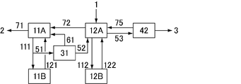
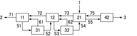
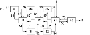
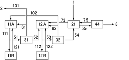
- FIG. 1 It is a figure which showed an example of the purification apparatus which performs the purification method of this invention. It is a figure which showed an example of the purification apparatus which performs the purification method of this invention. It is a figure which showed the purification apparatus which performed the purification of the crude acrylic acid solution in Comparative Examples 1 and 2. It is a figure which showed the purification apparatus which performed the purification of the crude acrylic acid solution in the comparative example 3.
- the purification method of the present invention has a predetermined configuration having a crystallization apparatus having N crystallization tanks or aging tanks including at least one crystallization tank, and a washing column provided with a mechanism for forcibly transporting crystals.
- the purified liquid containing the compound includes a step of supplying the portion to the washing column, and the purity of the mother liquid in the slurry supplied to the washing column is higher than that of the mother liquid discharged to the outside of the purification device. Purification is performed under the condition that the purity A1 of the mother liquor and the purity A2 of the mother liquor discharged to the outside of the purification apparatus are 80 mol% or more and the difference between the purity A1 and the purity A2 of the mother liquor is 5 mol% or more.
- the mother liquor is separated from the slurry containing the crystals of the compound by a crystallization device, and the slurry whose crystal concentration has increased until the mother liquor purity A1 of the slurry becomes 80 mol% or more is sent to the washing column, and the slurry is sent to the washing column. Since the amount of impurities contained is small, the amount of cleaning liquid used in the cleaning column can be reduced, so that the yield of crystals recovered from the purification apparatus can be increased and the variable cost can be reduced.
- the compound when the difference between the purity A1 of the mother liquor in the slurry supplied to the washing column and the purity A2 of the mother liquor discharged to the outside of the purification apparatus is 5 mol% or more, the compound is sufficiently removed from the purified liquid in the crystallization apparatus. It can be said that crystals can be generated, impurities can be concentrated in the mother liquor and discharged to the outside of the purification equipment, and as a result, more compounds can be obtained as a product from the purification liquid containing the compounds used in the purification equipment. Can be obtained at.
- the purity A1 of the mother liquor in the slurry supplied to the washing column may be 80 mol% or more, but preferably 82 mol% or more. More preferably, it is 83 mol% or more, and further preferably 84 mol% or more.
- the difference between the purity A1 of the mother liquor in the slurry supplied to the washing column and the purity A2 of the mother liquor discharged to the outside of the purification apparatus may be 5 mol% or more, but is preferably 6.5 mol% or more. It is more preferably 8 mol% or more, and further preferably 10 mol% or more.
- the purity of the mother liquor in the present invention refers to the purity of the compound to be purified for the total number of moles of the compound to be purified and other impurities (by-products, solvents, polymerization inhibitors, etc.) contained in the mother liquor. It is the ratio of the number of moles.
- the purification apparatus used in the purification method of the present invention has a crystallization apparatus in which N (N ⁇ 2) tanks are connected in series and a washing column for forcibly transporting crystals, and at least one contained in the crystallization apparatus.
- the second tank is a crystallization tank equipped with a cooling mechanism
- the second and subsequent tanks are crystallization tanks or aging tanks
- the Nth tank is connected to the washing column
- the tank is one upstream from the downstream tank.
- the slurry is sent to the tank, and the slurry is sent from the Nth tank to the washing column.
- At least one of the lines for sending the slurry from the downstream tank to the upstream tank in order is a line for sending the slurry to the upstream tank via the solid-liquid separation device, and is discharged from the solid-liquid separation device. It has a line to return at least a part of the slurry to the original tank.
- all of the 1st to N-1st tanks included in the crystallization apparatus are a line for directly sending the mother liquor from the tank one upstream, and the solid-liquid separation from the tank one upstream. It has at least one of the lines for sending the mother liquor via the apparatus, and further has a line for sending the mother liquor to the outside of the purification apparatus.
- the line for sending the mother liquor to the outside of the purification apparatus is preferably a line for sending the mother liquor from the most downstream tank to the outside of the purification apparatus, thereby the most downstream tank.
- a low-purity mother liquor (crystallization residue) enriched with impurities can be discharged in a smaller amount, and a high-purity compound can be obtained in a high yield.
- washing column a part of the liquid obtained by heating and melting the purified crystals is used as a washing liquid (reflux liquid) and brought into countercurrent contact with the crystal bed to increase the purity of the crystals, but the purity is high from the Nth tank.
- the amount of this cleaning liquid can be reduced by supplying crystals and mother liquor to the cleaning column.
- the step of forming a compound crystal in the crystallization device in the purification method of the present invention is a step of forming a compound crystal in the crystallization tank of the crystallization device, and the slurry containing the crystal has a crystal concentration of the mother liquor.
- the step of separating into the elevated slurry is a step of separating the slurry containing crystals into a mother liquor and a slurry having an increased crystal concentration by a solid-liquid separator.
- a crystallization device in which a plurality of crystallization tanks including at least one crystallization tank or an aging tank are connected in series is used, and the tank is directed from the downstream tank to the upstream tank.
- the step of sending the slurry taken out from the tank to the upstream tank is included, and at least one of the steps is a step of sending the slurry taken out from the tank to the upstream tank one via a solid-liquid separator. be.
- the step of supplying at least a part of the slurry from the crystallization device to the washing column is a step of supplying at least a part of the slurry from the most upstream tank included in the crystallization device to the washing column.
- At least one of the lines for sending the slurry from the downstream tank to the upstream tank in order sends the slurry to the upstream tank via the solid-liquid separation device. Has a liquid line. By doing so, it is possible to prevent crystals from being sent to the downstream tank, efficiently increase the purity of the tank in the upstream tank, and facilitate purification in the next step (washing column).
- the ratio of the line that sends the slurry to the one upstream tank via the solid-liquid separator is 60% or more. It is preferable to have. Most preferably, 100%, that is, all of the N-1 lines that feed the slurry from the downstream tank to the upstream tank, feed the slurry to the upstream tank via the solid-liquid separator. It is a line to do.
- those having a line for sending the slurry to the tank one upstream via the solid-liquid separator has at least a part of the mother liquor discharged from the solid-liquid separator as the original.
- the slurry containing the concentrated crystals which has a line to be returned to the tank and separated by the solid-liquid separator, is sent to the upstream tank, and at least a part of the remaining mother liquor is returned to the original tank. Will be done.
- all of the 1st to N-1th tanks are lines for directly sending the mother liquor from the upstream tank and one upstream as a line for sending the mother liquor from the upstream tank to the tank. It has at least one of the lines for sending the mother liquor from the tank of the above via a solid-liquid separator. Having these lines makes it possible to keep the liquid level in the tank constant.
- the method for purifying the compound of the present invention includes, for all of the 2nd to Nth tanks contained in the crystallization apparatus, a step of sending the mother liquor to the tank one downstream to adjust the liquid level of the tank. ..
- At least one of the 1st to N-1st tanks contained in the crystallization apparatus has a line for directly sending the mother liquor from the tank one upstream. More preferably, the N-1st tank has a line for directly feeding the mother liquor from the upstream tank (Nth tank).
- a crystal sedimentation region is provided in the upper part of the tank, and the mother liquor containing no crystals (hereinafter, may be referred to as a clear mother liquor) is sent by overflow.
- the method is known. This method does not require a liquid feed pump and has the advantage that the liquid level in each tank can be easily adjusted.
- this method requires a crystal sedimentation region in the upper part of the tank, which complicates the tank structure.
- the sedimentation rate of the crystals is slow, so it is necessary to make the tank itself excessively large in order to design the sedimentation region. .. If the crystals are too fine to form the sedimentation region well, the crystals may be sent to the downstream side and the purification effect as an apparatus may be reduced.
- the tank included in the crystallization device has a line for sending the mother liquor from the one upstream tank via the solid-liquid separator, the crystals are sent from the one upstream tank to the downstream side. Since the liquid level in the tank can be kept constant while being effectively suppressed by solid-liquid separation, the purification device is used even when the purification device is used to purify compounds with slow crystal settling speed by producing fine crystals. The purification efficiency of the crystal can be maintained high. Further, since it is not necessary to provide a crystal sedimentation region for acquiring the mother liquor in the tank itself, the size of the tank itself can be reduced.
- At least one is a line for sending the mother liquor from the upstream tank via the solid-liquid separator. Is preferable.
- the method for purifying a compound of the present invention includes a step of sending a mother liquor from at least one of the 2nd to Nth tanks contained in the crystallization device to a tank one downstream via a solid-liquid separation device. It is a preferred embodiment.
- a line for sending mother liquor via a solid-liquid separator is provided in a tank one downstream from the tank included in the crystallization device, it is one upstream from the viewpoint of the cost of the purification device itself and the operating cost of the device. It is preferable to share the solid-liquid separation device provided in the line for sending the slurry to the tank. By doing so, the number of equipment of the solid-liquid separator and the liquid feed pump can be reduced.
- one or more additional lines for further feeding the mother liquor are provided in the line for returning the mother liquor from the solid-liquid separation device provided in the line for sending the slurry to the tank one upstream.
- the device may be configured such that the additional line is connected to a tank one downstream from the original tank. Further, the additional line may be further branched to connect to two or more downstream tanks in addition to one downstream tank with respect to the original tank. Further, the additional line may be connected to the outside of the purification device.
- the crystallization device has such a configuration, that is, at least one of the solid-liquid separation devices provided in the line for sending the slurry from the downstream tank to the upstream tank returns the mother liquor to the original tank. It is the present invention that the return line has one or more additional lines for delivering the mother liquor, the additional lines being connected to the downstream tank and / or out of the purification apparatus with respect to the original tank. It is one of the preferable embodiments of the purification apparatus which carries out the purification method of.
- the ratio of those having such an additional line is preferably 30% or more, more preferably 60. % Or more, more preferably 100%.
- the solid-liquid separator commonly used means such as a basket type centrifuge, a decanter type centrifuge, a liquid cyclone, a filter, and a centrifuge can be used.
- An example of a basket-type centrifuge is the Escher Wis-extruded centrifuge of Tsukishima Kikai Co., Ltd.
- an example of a decanter-type centrifuge is a bird-decanter type centrifuge of Tsukishima Kikai Co., Ltd., and a screw of IHI Co., Ltd.
- a decanter type centrifuge and the like can be mentioned.
- the crystal concentration in the cake after solid-liquid separation is preferably 80% or more, more preferably 85% or more, still more preferably 90% or more.
- the crystal concentration after concentration is preferably 40% or more, more preferably 50% or more, still more preferably 60% or more.
- the crystal concentration in the concentrated slurry is preferably 25% or more, more preferably 30% or more, still more preferably 35% or more. If the slurry concentration is too high, the fluidity decreases and the risk of pipe blockage increases. Therefore, the slurry concentration after concentration is preferably 55% or less, more preferably 50% or less, still more preferably 45% or less.
- the crystallization apparatus includes a plurality of crystallization tanks or aging tanks including at least one crystallization tank.
- the total number of crystallization tanks and aging tanks is not particularly limited, but a basket-type centrifuge and a decanter-type centrifuge are used as the solid-liquid separator from the viewpoint of sufficiently improving the purity of crystals and mother liquor. In the case of 2, it is preferable, and in other cases, it is preferably 3 or more.
- the effect of improving the purity of crystals and mother liquor increases as the number of tanks increases, but if it is too large, capital investment increases and the power consumption of pumps, stirrers, etc. attached to the tanks also increases, which is disadvantageous. Become. Therefore, the total number of crystallization tanks and aging tanks is preferably 6 or less regardless of the type of solid-liquid separation device. More preferably, it is 5 or less.
- the other tanks may be a crystallization tank or an aging tank, but the number of aging tanks included in the crystallization device is 0. It is preferably up to two. More preferably, it is 0 to 1.
- the tank included in the crystallization device preferably has a structure capable of forming a clear mother liquor layer on the upper part, and any one of the 1st to N-1st tanks included in the crystallization device is one.
- the line is a line for directly feeding the clear mother liquor layer on the upper part of the upstream tank by overflow.
- the line for discharging the mother liquor to the outside of the purification device is a line for discharging the mother liquor to the outside of the purification device due to overflow, which is one of the preferred embodiments of the purification device for performing the purification method of the present invention.
- the purification apparatus of the present invention preferably has a line for sending the mother liquor from the most downstream first tank included in the crystallization apparatus to the outside of the purification apparatus, but the first line included in the crystallization apparatus. It is one of the preferred embodiments of the purification apparatus of the present invention that the line is to send the clear mother liquor layer on the upper part of the tank to the outside of the purification apparatus by overflow.
- the inclusion of the step of directly sending the clear mother liquor layer at the upper part of the tank from at least one of the 2nd to Nth tanks contained in the crystallization apparatus to the downstream tank by overflow is to purify the compound of the present invention.
- a preferred embodiment of the method is also suitable for the method for purifying a compound of the present invention, which comprises a step of directly discharging a layer of a clear mother liquor on the upper part of the tank from the first tank at the most downstream to the outside of the purification apparatus by overflow. It is an embodiment.
- a solid-liquid separation device is installed to separate the mother liquor and crystals from the slurry taken out from the tank by the solid-liquid separation device.
- One or more mother liquors can be sent to the downstream tank.
- the mother liquor separated by the solid-liquid separation device may be discharged to the outside of the purification device, and a line for discharging the mother liquor from the first tank included in the crystallization device to the outside of the purification device via the solid-liquid separation device may be provided.
- the method for purifying a compound of the present invention preferably includes a step of repurifying at least a part of the mother liquor discharged from the purification apparatus by a distillation operation and / or a crystallization operation.
- a step of repurifying at least a part of the mother liquor discharged from the purification apparatus and recovering the compounds contained in the discharged mother liquor By repurifying at least a part of the mother liquor discharged from the purification apparatus and recovering the compounds contained in the discharged mother liquor, the compounds contained in the residue discharged from the purification apparatus can be reduced.
- the recovered compound may be introduced into the purification apparatus again together with the purification liquid supplied to the purification equipment, or may be returned to the step before obtaining the purification liquid.
- the purification method of the present invention includes a step of introducing the compound recovered by the repurification step into the purification apparatus again, or a step of returning the recovered compound to a previous step for obtaining a liquid to be purified. It is an embodiment.
- all the tanks preferably 30% or more, more preferably 60% or more, and most preferably N-1st, separate the mother liquor into a solid solution.
- the structure is such that the liquid is sent to one downstream tank (or two or more downstream tanks in addition to the tank) via the device and / or discharged to the outside of the crystallization device. By doing so, the size of the tank can be reduced, and the investment amount and construction area can be reduced. Further, as described above, it is preferable that the solid-liquid separation device in this case is shared with the solid-liquid separation device provided in the line for sending the slurry to the tank one upstream from the viewpoint of cost.
- the capacity is larger than that of the downstream tank in order to retain / mature the slurry to be sent to the washing column, and the purity of the slurry is improved and crystals are formed more than the downstream tank. Due to its large diameter and easy growth, it is relatively easy to design the crystal sedimentation region at the top of the tank, that is, the clear mother liquor layer. Therefore, it is preferable that the Nth tank has a structure in which the mother liquor is directly sent to the downstream tank by overflow.
- the crystallization tank included in the crystallization device is provided with a cooling mechanism, and is particularly capable of cooling a solution of a compound to precipitate crystals and producing a slurry containing crystals and a mother liquor.
- a cooling jacket is attached to the tank itself to directly cool the inside of the tank to generate crystals, and the cooling mechanism is separated from the tank and connected by piping to generate cooling / crystals while circulating. It is roughly divided into.
- the method in which the cooling jacket is attached to the tank itself has the advantage of reducing the number of devices, but in order to increase the heat transfer area, it is necessary to increase the size of the tank itself. If high production capacity is required, the size of the tank will be excessively large, which will be a disadvantage in terms of initial investment and site area.
- the type in which the contents of the tank are cooled outside the tank is preferable.
- the tank and the cooling mechanism are connected by a pipe, and a part of the solution of the compound (or the slurry containing crystals) in the tank is sent to the cooling mechanism to generate crystals in the cooling mechanism.
- the heat transfer area can be easily increased by increasing the cooling mechanism, and the scale-up of the crystallization tank can be easily performed.
- the cooling mechanism in this case is not particularly limited as long as it can cool the solution of the compound to precipitate crystals, but it is a shell & tube type heat exchanger and spiral that can secure a large heat transfer area. It is preferable to use a type heat exchanger or the like, a cooling disk type crystallizer that crystallizes while scraping the cooling surface, a scraping type cooling crystallizer or the like.
- the cooling disk type crystallizer may be any as long as it cools the solution of the compound to precipitate crystals and scrapes the precipitated crystals, but it is composed of a tube and a plurality of cooling plates separating the inside thereof. It is possible to use a structure in which crystals are generated on the wall surface of the cooling plate and a stirring blade having a wiper is rotated inside the tube to scrape the crystals.
- the scraping-type cooling crystallizer may be any as long as it cools the solution of the compound to precipitate crystals and scrapes the precipitated crystals, but it is composed of a double-structured tube, and the refrigerant is applied to the outer tube.
- a solution of the compound in the tank (or a slurry containing crystals) is flowed through the inner tube to form crystals on the wall surface of the inner tube, and a shaft with a scraping blade is rotated inside the inner tube to crystallize.
- a structure that scrapes off can be used.
- a part of the solution of the compound (or the slurry containing the crystals) in the tank is sent to the cooling mechanism to be inside the cooling mechanism. It is a preferred embodiment of the method for purifying a compound of the present invention that the step of producing crystals in the above step and returning the slurry containing the produced crystals to the tank.
- the crystallization apparatus may or may not have an aging tank, but it is preferable to have an aging tank.
- the aging tank does not have a cooling mechanism for precipitating crystals, and is a tank for growing compound crystals by holding the compound crystals for a certain period of time.
- the tank for sending the liquid to the washing column that is, the Nth tank is the aging tank.
- the method for purifying a compound of the present invention preferably includes a step of aging a slurry containing crystals of the compound in an aging tank, and when the crystallization apparatus having the above N tanks is used, the crystallization apparatus is used. It is preferable to include a step of aging the slurry containing the crystals of the compound in the aging tank which is the Nth tank most upstream.
- the aging tank is not particularly limited as long as it can hold the crystal of the compound in a suspended state in the tank. By holding the crystals for a certain period of time, fine crystals are melted by Ostwald ripening, large crystals are further grown, the crystal diameter distribution is narrowed, and the purification efficiency in the washing column can be further improved. Further, even in the crystallization tank, the same effect as the aging tank can be expected by holding the crystals for a certain period of time.
- a slurry containing the crystals of the compound is sent from the crystallization device to the washing column included in the washing column including the purification device for performing the purification method of the present invention, the crystals are washed, and the crystals of the high-purity compound are obtained as a product.
- the washing column of the preferred form in the present invention when the specific gravity of the crystals is larger than that of the mother liquor, the crystals move downward in the column to form a crystal bed. Then, the crystal bed is scraped off at the lower part of the column and melted by heating, and a part of the obtained melt is extracted as a product. The remaining melt is used as a cleaning solution for countercurrent contact with the crystal bed to increase crystal purity.
- the mother liquor and the washing liquid in the washing column are returned to the crystallization device through the line for returning the liquid to the crystallization device.
- the line for returning the mother liquor to the crystallization apparatus is connected to at least the Nth tank, but may be further connected to a downstream tank. Further, it may have a line for returning a part of the mother liquor to the washing column again.
- the method for purifying a compound of the present invention includes a step of sending a slurry containing a compound crystal from the Nth tank of the crystallization apparatus to a washing column. Is preferable. In addition, some crystals are extracted from the lower part of the washing column and melted by heating, a part of the obtained melt is extracted as a product, and the remaining melt is returned to the washing column to make countercurrent contact with the crystal bed in the column. It is preferable to include a step of cleaning the crystals.
- the method for purifying the compound of the present invention preferably includes a step of returning the mother liquor from the washing column to the crystallization device, and when the crystallization device having the above N tanks is used, N from the washing column to the crystallization device. It is preferable to include a step of returning the mother liquor to the second tank or a tank further downstream. Further, a step of returning a part of the mother liquor taken out from the washing column to the washing column may be included.
- the washing column in the present invention forcibly conveys the crystal bed.
- a mechanical cleaning column that compacts crystals with a piston to form / transport a crystal bed
- a pump sends slurry to the column
- a bed is extracted from a filter placed in the column.
- a hydraulic cleaning column (hydraulic cleaning column) or the like for forming / transporting the slurry can be mentioned.
- the operating principle of these cleaning columns is described in the book Melt Crystallization (Edited by Joachim Ullrich, Heike Glade, Shaker Verlag, Aachen 2003).
- the washing column is not particularly limited as long as it can wash the crystals, and may be either a mechanical washing column or a hydraulic washing column.
- Mechanical cleaning columns are characterized by high stability during operation and high compound purification efficiency.
- the hydraulic cleaning column is characterized in that it has a high production capacity per column cross-sectional area, there are few driving parts in the cleaning column, and there are few troubles caused by the equipment.
- purifying an easily polymerizable substance it may be possible to suppress the generation of a polymer in the cleaning column by using a hydraulic cleaning column having a small number of driving parts.
- Preferred forms of the wash column include those having a mechanical mechanism for scraping the crystal bed (see US Pat. No. 3,872009A).
- a washing column having a forced transport mechanism for a crystal bed a method is used in which the purified crystal bed is scraped off with a scraper or the like, resuspended, and then melted.
- wash column is one that does not have a mechanical mechanism for scraping the crystal bed (see US Pat. No. 7,425273B2).
- the crystal bed is scraped by the dynamic pressure of the circulating fluid. Since there is no sliding surface such as a shaft seal portion, the generation of a polymer due to liquid retention, sliding heat, etc. may be suppressed in the purification of easily polymerizable substances.
- the solution of the compound as the liquid to be purified may be supplied to the purification apparatus for performing the purification method of the present invention to any of the tanks included in the crystallization apparatus, but from the viewpoint of purification efficiency, the second and subsequent tanks may be supplied. It is preferable to do this for the tank.
- the method for purifying a compound of the present invention preferably includes a step of supplying a compound-containing solution as a liquid to be purified to the second and subsequent tanks.
- the optimum location varies depending on the supply liquid composition, crystallization yield, and crystal concentration efficiency in the solid-liquid separation device, and can be appropriately selected.
- the crystallization temperature in the crystallization tank in the purification method of the present invention may be appropriately adjusted according to the type of the compound to be purified, but is generally -1 to -15 ° C., preferably-with respect to the melting point of the pure substance.
- the temperature is in the range of 1.5 to -13.5 ° C, more preferably ⁇ 3.5 to -12.5 ° C, and even more preferably ⁇ 5 to -11.5 ° C.
- the temperature is preferably 0 to 12 ° C. It is more preferably 1 to 10 ° C, still more preferably 2 to 8.5 ° C. Therefore, it is preferable that the step of forming crystals of the compound by the crystallization apparatus in the method for purifying the compound of the present invention is performed at these temperatures.
- High-purity crystals are produced when the temperature of the crystallization tank is high.
- the crystallization tank uses a scraping-type cooling crystallizer described later, it is suitable for crystal scraping in the crystallization tank.
- problems such as the need for a large amount of power.
- problems such as blocking of the scraping scraper may occur when the crystallization tank uses a scraping type cooling crystallizer, and operation may occur. It can be difficult to continue.
- the temperature of the crystallization tank is high, it is necessary to reduce the temperature difference between the refrigerant and the crystallization tank and reduce the amount of crystals produced per heat transfer area. If the temperature of the crystallization tank is low, the purity of the produced crystals will decrease, but if the crystallization tank uses a scraping type cooling crystallizer, the power required for scraping the crystals in the crystallization tank can be small. Even if the temperature difference between the refrigerant and the crystallization tank is increased, scraper blocking is unlikely to occur. As a result, the temperature difference between the refrigerant and the crystallization tank can be increased, and the amount of crystals produced per heat transfer area can be increased. However, if the crystallization temperature is too low, the crystal grain size produced becomes fine and the crystals tend to be difficult to settle.
- the residence time of the compound in the crystallization tank and the aging tank may be appropriately adjusted according to the type of the compound to be purified, but considering the yield of the compound obtained after purification, the efficiency of purification, and the capital investment cost, the crystals are crystallized.
- the residence time in the 1st to N-1st tanks contained in the analyzer is approximately 0.02 to 6 hours.
- the residence time is longer than a certain level in order to arrange the particle size distribution of the slurry to be sent to the washing column and reduce the reflux ratio (washing liquid flow rate / purified acrylic acid flow rate) in the washing column. It is preferably 0.5 to 6 hours, more preferably 1 to 5 hours, and even more preferably 1.2 to 4.5 hours.
- the residence time is preferably 0.03 to 4 hours, more preferably 0.04 to 3 hours, still more preferably 0.05 to 2 hours, and most preferably 0.05 to 2 hours. 0.1 to 1.5 hours.
- the residence time of the compound in the crystallization tank here means that when the crystallization tank is of a type that cools the contents of the tank described later outside the tank, it stays in the cooling mechanism inside and outside the tank. Means time to do.
- the residence time of each tank is the combined capacity of the tank and the cooling mechanism outside the tank, the flow rate for supplying the slurry to the tank or washing column upstream from the tank, and the liquid from each tank to the lower tank or outside the purification device. It is calculated as the value obtained by dividing the flow rate of liquid delivery / discharge by the sum of the flow rates.
- the purification method of the present invention may be used for purification of any compound, but as described above, it can also be suitably used for purification of crystals having poor precipitation property, and is therefore suitable for purification of (meth) acrylic acid. Can be used for. Therefore, it is one of the preferred embodiments of the present invention that the compound purified by the purification method of the present invention is (meth) acrylic acid.
- the solution of the compound used in the purification method of the present invention is a (meth) acrylic acid aqueous solution or a crude (meth) acrylic acid solution.
- the (meth) acrylic acid aqueous solution means a solution in which (meth) acrylic acid is dissolved in water.
- the crude (meth) acrylic acid solution is a solution composed of (meth) acrylic acid and contains impurities such as by-products during the production of (meth) acrylic acid. These can be obtained, for example, by collecting the gas of the compound, which is a reaction product obtained by the gas phase oxidation reaction of propylene and isobutylene, in an absorption tower and distilling if necessary, but can be obtained by synthesizing it by itself.
- a (meth) acrylic acid aqueous solution or a crude (meth) acrylic acid solution can be cooled, for example, to obtain a slurry containing crystals of (meth) acrylic acid.
- Examples of the by-products include acids such as propionic acid, acetic acid, maleic acid, benzoic acid and acrylic acid dimer, aldehydes such as acrolein, furfural, formaldehyde and glyoxal, acetone and protoanemonin. ..
- a solvent such as toluene or methyl butyl ketone may be contained.
- (meth) acrylic acid is acrylic acid and / or methacrylic acid.
- FIG. 1 shows an apparatus having one crystallization tank and one aging tank as a crystallization apparatus, and a line for directly sending the mother liquor from the aging tank, which is one upstream tank, is installed in the crystallization tank.
- a line is installed to directly discharge the residue (mother solution) from the crystallization tank, which is the most downstream tank.
- the solution 1 of the compound used in the purification apparatus is introduced into the aging tank 21.
- the slurry containing the crystals cooled by the crystallization tank 11 in which the cooling mechanism is installed is sent to the solid-liquid separation device 31 by the line 51.
- the slurry is separated into a mother liquor and a concentrated crystal slurry, the concentrated crystal slurry is sent to the adjacent aging tank 21 on the line 52, and the mother liquor is returned to the crystallization tank 11 on the line 61. .. Further, the residue 2 is discharged from the crystallization tank 11 to the outside of the purification apparatus on the line 71, and the liquid level of the crystallization tank 11 is adjusted. After growing the crystals in the aging tank 21, the crystal slurry is sent to the mechanical cleaning column 41 on the line 53. Further, in order to adjust the liquid level of the aging tank 21, the mother liquor is directly sent from the aging tank 21 to the crystallization tank 11 through the line 72.
- the crystals are compacted by the piston to form a crystal bed. Then, the crystal bed is scraped off at the lower part of the column, suspended in a circulating solution, and melted by heating. A part of the circulating fluid containing the obtained melt is carried out as high-purity compound 3. A part of the remaining circulating liquid (cleaning liquid) is returned to the mechanical cleaning column 41 and brought into countercurrent contact with the crystal bed to clean the crystals. Further, the mother liquor in the washing column is returned to the aging tank 21 through the line 75 for returning the mother liquor to the crystallization apparatus. The compound is purified in this way, and a high-purity compound is obtained.
- FIG. 2 shows a device having one crystallization tank and one aging tank as a crystallization device, and a line for directly sending the mother liquor from the aging tank, which is one upstream tank, is installed in the crystallization tank.
- a line is installed to discharge the residue (mother solution) from the crystallization tank, which is a downstream tank, via a solid-liquid separation device.
- a hydraulic column is used as the cleaning column. Only the parts different from the purification apparatus of FIG. 1 will be described below.
- the slurry containing the crystals cooled by the crystallization tank 11 in which the cooling mechanism is installed is sent to the solid-liquid separation device 31 by the line 51.
- the slurry is separated into a mother liquor and a concentrated crystal slurry, the concentrated crystal slurry is sent to the adjacent aging tank 21 on the line 52, and a part of the mother liquor is sent to the crystallization tank 11 on the line 61.
- the balance is discharged to the outside of the purification apparatus as residue 2 on the line 101, and the liquid level of the crystallization tank 11 is adjusted.
- the hydraulic cleaning column 43 the crystals move downward to form a crystal bed. Then, the crystal bed is scraped off at the lower part of the column, suspended in a circulating solution, and melted by heating.
- the hydraulic cleaning column 43 does not have a mechanical mechanism for scraping the crystal bed, and the crystal bed is scraped by the dynamic pressure of the circulating liquid.
- FIG. 3 shows a device having one crystallization tank and one aging tank as a crystallization device, and a line for directly sending the mother liquor from the aging tank, which is one upstream tank, is installed in the crystallization tank, and is the most downstream.
- a line is installed to directly discharge the residue (mother solution) from the crystallization tank, which is the tank of the above.
- the crystallization tank a tank in which the contents of the tank are cooled outside the tank is used. Only the parts different from the purification apparatus of FIG. 1 will be described below.
- the crystallization tank 11 is composed of a tank 11A and a cooling mechanism 11B outside the tank, and is connected by lines 111 and 121.
- the solution of the compound (or the slurry containing the crystals of the compound) sent from the tank 11A to the cooling mechanism 11B on the line 111 is cooled by the cooling mechanism 11B, and the slurry containing the precipitated crystals is sent to the tank 11A on the line 121.
- a part of the slurry containing the compound crystals is sent from the tank 11A to the cooling mechanism 11B by the line 111, and the rest is sent to the solid-liquid separation device 31 by the line 51.
- FIG. 4 shows an apparatus having two crystallization tanks as a crystallization apparatus, and a line for directly sending the mother liquor from the crystallization tank 12 which is one upstream tank is installed in the crystallization tank 11, and is the most downstream.
- a line is installed to directly discharge the residue (mother solution) from the crystallization device 11 which is a tank.
- a hydraulic column is used as the cleaning column. Only the parts different from the purification apparatus of FIG. 1 will be described below.
- the solution 1 of the compound used in the purification apparatus is introduced into the crystallization tank 12.
- the crystallization tank 11 is composed of a tank 11A and a cooling mechanism 11B outside the tank, and is connected by lines 111 and 121.
- the solution of the compound (or the slurry containing the crystals of the compound) sent from the tank 11A to the cooling mechanism 11B on the line 111 is cooled by the cooling mechanism 11B, and the slurry containing the precipitated crystals is sent to the tank 11A on the line 121.
- a part of the slurry containing the compound crystals is sent from the tank 11A to the cooling mechanism 11B by the line 111, and the rest is sent to the solid-liquid separation device 31 by the line 51.
- the crystallization tank 12 is also composed of a tank 12A and a cooling mechanism 12B outside the tank, and is connected by lines 112 and 122.
- a part of the slurry containing the crystal of the compound is sent from the tank 12A to the cooling mechanism 12B by the line 112, and is returned to the tank 12A by the line 122.
- the crystal slurry is sent from the crystallization tank 12 to the hydraulic cleaning column 42 by the line 53.
- the crystal bed is scraped off by a mechanical mechanism (scraper) and melted by heating while being suspended in the circulating fluid, and a part of the circulating fluid containing the obtained molten fluid is used as high-purity compound 3. It is carried out.
- a part of the remaining circulating liquid (cleaning liquid) is returned to the hydraulic cleaning column 42 and brought into countercurrent contact with the crystal bed to wash the crystals. Further, the mother liquor in the washing column is returned to the crystallization tank 12 through the line 75 for returning the mother liquor to the crystallization apparatus.
- FIG. 5 shows a device having two crystallization tanks and one aging tank as a crystallization device, and a line for directly sending the mother liquor from one upstream tank is installed between the three tanks, and the most downstream.
- a line is installed to directly discharge the residue (mother solution) from the tank.
- the cleaning column is hydraulic and has a mechanical mechanism for scraping the crystal bed.
- the slurry containing the crystals cooled by the crystallization tank 11 in which the cooling mechanism is installed is sent to the solid-liquid separation device 31 by the line 51.
- the slurry is separated into a mother liquor and a concentrated crystal slurry, the concentrated crystal slurry is sent to the adjacent crystallization tank 12 on the line 52, and the mother liquor is returned to the crystallization tank 11 on the line 61. Is done. Further, the residue 2 is discharged from the crystallization tank 11 to the outside of the purification apparatus on the line 71, and the liquid level of the crystallization tank 11 is adjusted. In the crystallization tank 12, the same operation as in the crystallization tank 11 is performed, and the slurry containing the crystals is sent from the crystallization tank 12 to the solid-liquid separation device 32 along the line 53.
- the slurry is separated into a mother liquor and a concentrated crystal slurry, the concentrated crystal slurry is sent to the adjacent aging tank 21 on the line 54, and the mother liquor is returned to the crystallization tank 12 on the line 62. .. Further, in order to adjust the liquid level of the crystallization tank 12, the mother liquor is directly sent from the crystallization tank 12 to the crystallization tank 11 through the line 72. After growing the crystals in the aging tank 21, the crystal slurry is sent to the hydraulic cleaning column 42 on the line 55. Further, in order to adjust the liquid level of the aging tank 21, the mother liquor is directly sent from the aging tank 21 to the crystallization tank 12 through the line 73 connecting the aging tank 21 and the crystallization tank 12.
- the crystal bed is scraped off by a mechanical mechanism (scraper), and the crystal bed is extracted while being suspended in the circulating fluid and melted by heating. It is carried out as 3. A part of the remaining circulating liquid (cleaning liquid) is returned to the hydraulic cleaning column 42 and brought into countercurrent contact with the crystal bed to wash the crystals.
- FIG. 6 shows a device having three crystallization tanks and one aging tank as a crystallization device, and a line for directly sending the mother liquor from one upstream tank is installed between the four tanks, and the most downstream.
- a line is installed to directly discharge the residue (mother solution) from the tank.
- the cleaning column is hydraulic and has a mechanical mechanism for scraping the crystal bed.
- the solution 1 of the compound used in the purification apparatus is introduced into the crystallization tank 13.
- the slurry containing crystals is sent from the crystallization tank 12, which is the second tank from the most downstream, to the solid-liquid separation device 32 along the line 53.
- the slurry is separated into a mother liquor and a concentrated crystal slurry, the concentrated crystal slurry is sent to the adjacent crystallization tank 13 on the line 54, and the mother liquor is returned to the crystallization tank 12 on the line 62. Is done. Further, in order to adjust the liquid level of the crystallization tank 12, the mother liquor is directly sent from the crystallization tank 12 to the crystallization tank 11 through the line 72. The same operation as in the crystallization tank 12 is performed in the crystallization tank 13, and the slurry containing the crystals is sent from the crystallization tank 13 to the solid-liquid separation device 33 along the line 55.
- the slurry is separated into a mother liquor and a concentrated crystal slurry, the concentrated crystal slurry is sent to the adjacent aging tank 21 on the line 56, and the mother liquor is returned to the crystallization tank 13 on the line 63. .. Further, in order to adjust the liquid level of the crystallization tank 13, the mother liquor is directly sent from the crystallization tank 13 to the crystallization tank 12 through the line 73. After growing the crystals in the aging tank 21, the crystal slurry is sent to the hydraulic cleaning column 42 on the line 57. Further, in order to adjust the liquid level of the aging tank 21, the mother liquor is directly sent from the aging tank 21 to the crystallization tank 13 through the line 74 connecting the aging tank 21 and the crystallization tank 13.
- FIG. 7 shows a device having two crystallization tanks and one aging tank as a crystallization device, and a line for sending mother liquor from one upstream tank between three tanks via a solid-liquid separation device. Is installed, and a line is installed to discharge the residue from the most downstream tank via a solid-liquid separator.
- a solid-liquid separation device 33 for separating the residue from the slurry in the crystallization tank is installed in place of the line for directly discharging the residue, and the slurry taken out from the crystallization tank 11 is provided.
- the residue 2 separated by the solid-liquid separation device 33 is discharged to the outside of the purification device, the remaining crystals are returned to the crystallization tank 11, and the liquid in the crystallization tank 11 is discharged. The surface is adjusted.
- a solid-liquid separation device 34 is installed in place of the line that directly sends the mother liquor to the crystallization tank 11, and the slurry taken out from the crystallization tank 12 is sent to the solid-liquid separation device 34 by the line 83.
- the mother liquor sent and separated by the solid-liquid separation device 34 is sent to the crystallization tank 11 for liquid level adjustment, and the remaining crystals are returned to the crystallization tank 12.
- a solid-liquid separation device 35 is installed in place of the line that directly sends the mother liquor to the crystallization tank 12, and the slurry taken out from the aging tank 21 is sent to the solid-liquid separation device 35 by the line 85.
- the mother liquor separated by the solid-liquid separation device 35 is sent to the crystallization tank 12 for liquid level adjustment, and the remaining crystals are returned to the aging tank 21.
- the cleaning column 43 is a hydraulic type and does not have a mechanical mechanism for scraping the crystal bed.
- FIG. 8 shows a device having two crystallization tanks and one aging tank as a crystallization device, and a line for sending mother liquor from one upstream tank between three tanks via a solid-liquid separation device.
- a line is installed to discharge the residue from the most downstream tank via the solid-liquid separator, and the mother liquor is separated from the slurry taken out from the second crystallization tank and discharged to the most downstream
- the slurry containing the crystals cooled by the crystallization tank 11 and precipitated is sent to the solid-liquid separation device 31 by the line 51.
- the slurry is separated into a mother liquor and a concentrated crystal slurry, and the concentrated crystal slurry is sent to the adjacent crystallization tank 12 by the line 52.
- a part of the mother liquor separated by the solid-liquid separation device 31 is returned to the crystallization tank 11 by the line 61, and the rest is discharged to the outside of the purification device by the additional line 101 connected to the line 61.
- the slurry containing the crystals cooled and precipitated in the crystallization tank 12 is sent to the solid-liquid separation device 32 by the line 53.
- the slurry is separated into a mother liquor and a concentrated crystal slurry, and the concentrated crystal slurry is sent to the adjacent aging tank 21 by the line 54.
- a part of the mother liquor separated by the solid-liquid separation device 32 is returned to the crystallization tank 12 by the line 62, and the rest is sent to the crystallization tank 11 by the additional line 102 connected to the line 62.
- the line 51 ⁇ solid-liquid separation device 31 ⁇ lines 61, 101 correspond to the line 81 ⁇ solid-liquid separation device 33 ⁇ lines 82, 91 in the device of FIG. 7, and the solid-liquid separation device 33 is installed. Instead, the number of devices is reduced by sharing the solid-liquid separation device 31 provided in the line for sending the slurry to the upstream tank.
- line 53 ⁇ solid-liquid separation device 32 ⁇ line 62, 102 corresponds to line 83 ⁇ solid-liquid separation device 34 ⁇ lines 84, 92 in the device of FIG. 7, and instead of installing the solid-liquid separation device 34, The number of devices is reduced by sharing the solid-liquid separation device 32 provided in the line for sending the slurry to the upstream tank.
- FIG. 9 shows a device having two crystallization tanks and one aging tank as a crystallization device, from the second crystallization tank to the most downstream (first) crystallization tank via a solid-liquid separation device.
- a line for sending the mother liquor and a line for discharging the residue from the most downstream tank via the solid-liquid separator are installed, and a line for sending the mother liquor directly from the aging tank to the second crystallization tank is installed.
- This is a solid-liquid separation device for separating the mother liquor from the slurry taken out from the second crystallization tank and sending it to the most downstream crystallization tank, and from the most downstream crystallization tank to the outside of the purification device.
- the solid-liquid separation device for separating the discharged residue is shared with the solid-liquid separation device provided in the line for sending the slurry to the tank one upstream. Further, as the crystallization tank, a tank in which the contents of the tank are cooled outside the tank is used. Hereinafter, only the parts different from the purification apparatus of FIG. 8 will be described.
- the crystallization tank 11 is composed of a tank 11A and a cooling mechanism 11B outside the tank, and is connected by lines 111 and 121.
- the solution of the compound (or the slurry containing the crystals of the compound) sent from the tank 11A to the cooling mechanism 11B on the line 111 is cooled by the cooling mechanism 11B, and the slurry containing the precipitated crystals is sent to the tank 11A on the line 121.
- a part of the slurry containing the compound crystals is sent from the tank 11A to the cooling mechanism 11B by the line 111, and the rest is sent to the solid-liquid separation device 31 by the line 51.
- the crystallization tank 12 is also composed of a tank 12A and a cooling mechanism 12B outside the tank, and is connected by lines 112 and 122.
- a part of the slurry containing the crystal of the compound is sent from the tank 12A to the cooling mechanism 12B by the line 112, and the rest is sent to the solid-liquid separation device 32 by the line 53.
- the line 73 for sending the mother liquor directly from the aging tank 21 to the tank 12A. Have.
- Example 1 The crude acrylic acid solution obtained in Production Example 1 was supplied to a purification apparatus having the same structure as that of FIG. 2, and acrylic acid was continuously purified.
- a crude acrylic acid solution is continuously supplied to the second tank 21 at 10 kg / h, and crystals of acrylic acid are generated by a cooling mechanism (heat exchanger) provided in the first crystallization tank to form crystals.
- the slurry consisting of the mother liquor was sent to the upstream tank 21 by the line 52 while concentrating the crystals with the solid-liquid separator 31. Further, the mother liquor containing no crystals is sent directly from the second tank 21 to the first tank 11 by overflow (72), and the mother liquor is discharged from the first tank 11 to the outside of the crystallization device via the solid-liquid separation device 31.
- the liquid level in each tank was adjusted to be constant.
- a basket-type centrifuge was used as the solid-liquid separator 31, and the crystal concentration in the concentrated slurry was 90%, and the crystal concentration in the slurry held in the second tank 21 was 25%.
- the slurry was continuously sent from the second tank 21 to the hydraulic cleaning column 43 to purify and melt the crystals, and a part of the molten liquid was used as a cleaning liquid for cleaning the crystal bed on the cleaning column.
- the balance was obtained as purified acrylic acid at 6 kg / h.
- the amount of cleaning liquid was adjusted so that the furfural concentration in the product was less than 1 ppm. Further, the mother liquor was withdrawn from the upper part of the washing column and returned to the second tank 21 (75).
- the flow rate of the mother liquor (crystallization residue) discharged from the first tank 11 to the outside of the purification device via the solid-liquid separation device 31 was 4.0 kg / h.
- the yield as a crystallization device during steady operation (purified acrylic acid flow rate / crude acrylic acid flow rate ⁇ 100) was 60%, and the reflux ratio in the washing column (cleaning liquid flow rate / purified acrylic acid flow rate) was 0.43. ..
- the composition of the purified acrylic acid was as follows.
- the acrylic acid concentration (purity of the mother liquor) in the mother liquor in the tank is 73.4 mL in the tank 11, 90.2 mL in the tank 21, and the temperature of each tank is 3.3 ° C in the tank 11 and 9.8 ° C in the tank 21. Met.
- Example 2 The crude acrylic acid solution obtained in Production Example 1 was supplied to a purification apparatus having the same structure as that of FIG. 9, and acrylic acid was continuously purified.
- a crude acrylic acid solution is continuously supplied to the third tank 21 at 10 kg / h, and acrylic crystals are generated by cooling mechanisms (heat exchangers) 11B and 12B provided outside the first and second tanks.
- the slurry composed of the crystals and the mother liquor was sent to the upstream tank while concentrating the crystals with the liquid cyclones 31 and 32 (52, 54).
- the mother liquor containing no crystals is sent directly from the third tank 21 to the second tank 12A by overflow (73), and the mother liquor is sent from the second tank 12A to the first tank 11A via the solid-liquid separation device 32.
- the mother liquor was withdrawn from the upper part of the washing column and returned to the third tank 21 (75).
- the flow rate of the mother liquor (crystallization residue) discharged from the first tank 11A was 4.0 kg / h.
- the yield as a crystallization device during steady operation (purified acrylic acid flow rate / crude acrylic acid flow rate ⁇ 100) was 60%, and the reflux ratio in the washing column (cleaning liquid flow rate / purified acrylic acid flow rate) was 0.67. ..
- the composition of the purified acrylic acid was as follows.
- the acrylic acid concentration (purity of the mother liquor) in the mother liquor in the tank is 73.4 mL in the tank 11A, 81.0 mL in the tank 12A, 86.4 mL in the tank 21, and the temperature of each tank is 3.3 ° C in the tank 11A.
- the temperature was 6.3 ° C. in the tank 12A and 8.3 ° C. in the tank 21.
- the residence time in each tank was 1.0 hour in the tank 11A, 0.4 hours in the tank 12A, and 1.8 hours in the tank 21.
- Example 3 The crude acrylic acid solution obtained by the same method as in Production Example 1 was supplied to a purification apparatus having the same structure as in FIG. 5, and acrylic acid was continuously purified.
- the crude acrylic acid solution is continuously supplied to the third tank 21 at 10 kg / h, and instead of sending the mother liquor from the second tank 12 to the first tank 11 via the solid-liquid separator, it is directly overflowed.
- the mother liquor containing no crystals was sent (72), and instead of discharging the mother liquor from the first tank 11 to the outside of the crystallization device via the solid-liquid separation device, the mother liquor containing no crystals was discharged directly by overflow (71). ), Purification was carried out in the same manner as in Example 2 to obtain purified acrylic acid at 6 kg / h.
- the yield as a crystallization device during steady operation was 60%, and the reflux ratio in the washing column (cleaning liquid flow rate / purified acrylic acid flow rate) was 0.69. ..
- the composition of the purified acrylic acid was as follows.
- the acrylic acid concentration (purity of the mother liquor) in the mother liquor in the tank is 72.8 mL in the tank 11, 80.7 mL in the tank 12, 86.1 mL in the tank 21, and the temperature of each tank is 3.1 ° C in the tank 11.
- the temperature was 6.1 ° C. in the tank 12 and 8.2 ° C. in the tank 21.
- Comparative Example 1 The crude acrylic acid solution obtained by the same method as in Production Example 1 was supplied to a purification apparatus having the same structure as in FIG. 10, and acrylic acid was continuously purified.
- a crude acrylic acid solution is continuously supplied to the tank 11 at 10 kg / h, acrylic crystals are generated by the heat exchanger provided in the tank 11, and the crystal concentration in the slurry in the tank is 25%.
- the refrigerant temperature was adjusted.
- the slurry is continuously sent from the tank 11 to the hydraulic cleaning column 43 to purify and melt the crystals, and a part of the molten liquid is used as a cleaning liquid for cleaning the crystal bed on the cleaning column, and the rest is used. Obtained as purified acrylic acid (3).
- the amount of cleaning liquid was adjusted so that the furfural concentration in the product was less than 1 ppm. Further, the mother liquor was withdrawn from the upper part of the washing column and returned to the tank 11 (75), and the mother liquor containing no crystals was discharged from the tank as a crystallization residue so that the liquid level became constant by overflow (71). The flow rate of purified acrylic acid / the flow rate of slurry to be fed to the washing column was adjusted so that the concentration of acrylic acid in the mother liquor in the tank 11 was 86 mL.
- the yield as a crystallization device during steady operation (purified acrylic acid flow rate / crude acrylic acid flow rate ⁇ 100) was 16%, and the reflux ratio in the washing column (cleaning liquid flow rate / purified acrylic acid flow rate) was 0.67. ..
- the flow rate of the purified acrylic acid was 1.6 kg / h, and the composition was as follows.
- the crystallization residue flow rate was 8.4 kg / h.
- the acrylic acid concentration (purity of the mother liquor) in the mother liquor in the tank 11 was 86.4 mL, the temperature in the tank 11 was 8.3 ° C., and the residence time in the tank 11 was 2.0 hours.
- Comparative Example 2 The crude acrylic acid solution obtained by the same method as in Production Example 1 was supplied to a purification apparatus having the same structure as in FIG. 10, and acrylic acid was continuously purified.
- a crude acrylic acid solution is continuously supplied to the tank 11 at 10 kg / h, acrylic crystals are generated by the heat exchanger provided in the tank 11, and the crystal concentration in the slurry in the tank is 25%.
- the temperature of the refrigerant was adjusted.
- the slurry is continuously sent from the tank 11 to the hydraulic cleaning column 43 to purify and melt the crystals, and a part of the molten liquid is used as a cleaning liquid for cleaning the crystal bed on the cleaning column, and the rest is used. Obtained as purified acrylic acid at 6 kg / h (3).
- the amount of cleaning liquid was adjusted so that the furfural concentration in the product was less than 1 ppm. Further, the mother liquor was taken out from the upper part of the washing column and returned to the tank 11 (75), and the mother liquor containing no crystals was discharged from the tank as a crystallization residue by overflow (71) so that the liquid level became constant.
- the yield as a crystallization device (purified acrylic acid flow rate / crude acrylic acid flow rate ⁇ 100) was 60%, and the reflux ratio (cleaning liquid flow rate / purified acrylic acid flow rate) in the washing column 41 was 4.0.
- the composition of the purified acrylic acid was as follows. The flow rate of the crystallization residue was 4 kg / h.
- the acrylic acid concentration (purity of the mother liquor) in the mother liquor in the tank 11 was 73.4 mL, the temperature in the tank 11 was 3.3 ° C., and the residence time in the tank 11 was 1.5 hours.
- high-purity purified acrylic acid could be obtained through a series of purification operations, the reflux ratio in the washing column was high, and a large amount of energy was required to obtain the product.
- ⁇ Composition of purified acrylic acid> Acrylic acid 99.6% Acetic acid 2500ppm Furfural 0.9ppm Maleic acid 6.2ppm Benzaldehyde 0.5ppm Water 30ppm Hydroquinone 0.7ppm Other 1100ppm
- Comparative Example 3 The crude acrylic acid solution obtained by the same method as in Production Example 1 was supplied to a purification apparatus using a gravity-precipitation column having the same structure as that of FIG. 11, and acrylic acid was continuously purified. A crude acrylic acid solution is continuously supplied to the third tank 21 at 10 kg / h, and acrylic crystals are generated by the cooling mechanisms 11B and 12B provided outside the first and second tanks to generate crystals and mother liquor. The slurry composed of the above was sent to the upstream tank while concentrating the crystals with liquid cyclones 31 and 32 (52, 54).
- the mother liquor containing no crystals is sent directly from the third tank 21 to the second tank 12A by overflow (73), and the mother liquor is sent from the second tank 12A to the first tank 11A via the solid-liquid separation device 32.
- the mother liquor was discharged from the first tank 11A to the outside of the crystallization device via the solid-liquid separation device 31 (101), whereby the liquid level in each tank was adjusted to be constant.
- the crystal concentration in the slurry concentrated with the liquid cyclone was 40%, and the crystal concentration in the slurry held in the third tank 21 was 25%.
- the slurry is continuously sent from the third tank 21 to the gravity sedimentation type washing column 44 to purify and melt the crystals, and a part of the melt is used as a washing liquid for washing the crystal bed in the washing column.
- the balance was obtained as purified acrylic acid at 6 kg / h (3).
- the mother liquor was taken out from the upper part of the washing column and returned to the third tank 21 (75).
- the mother liquor (crystallization residue) discharged from the first tank 11A by overflow was 4.0 kg / h.
- the yield purified acrylic acid flow rate / crude acrylic acid flow rate ⁇ 100) as a crystallization device during steady operation was 60%.
- the reflux ratio cleaning liquid flow rate / purified acrylic acid flow rate
- the composition of the acid was as follows, and it was not possible to obtain a product of the desired quality.
- the acrylic acid concentration (purity of the mother liquor) in the mother liquor in the tank was 73.4 mL in the tank 11A, 82.6 mL in the tank 12A, 88.7 mL in the tank 21, and the temperature in the tank was 3 in the tank 11A. The temperature was 3.3 ° C., 6.8 ° C.
- the obtained purified acrylic acid contains a large amount of furfural, which is a polymerization retarder, and hydroquinone, which is a polymerization inhibitor, and is unsuitable for use as a raw material such as a highly water-absorbent resin.
- ⁇ Composition of purified acrylic acid Acrylic acid 99.7% Acetic acid 1500ppm Furfural 19ppm Maleic acid 120ppm Benzaldehyde 8ppm Water 500ppm Hydroquinone 12ppm Other 1100ppm
- Comparative Example 4 The crude acrylic acid solution obtained by the same method as in Production Example 1 was supplied to a purification apparatus having the same structure as that of FIG. 9, and acrylic acid was continuously purified.
- a crude acrylic acid solution is continuously supplied to the third tank 21 at 10 kg / h, and acrylic crystals are generated by the cooling mechanisms 11B and 12B provided outside the first and second tanks to generate crystals and mother liquor.
- the slurry composed of the above was sent to the upstream tank while concentrating the crystals with liquid cyclones 31 and 32 (52, 54). Further, the mother liquor containing no crystals is sent directly from the third tank 21 to the second tank 12A by overflow (73), and the mother liquor is sent from the second tank 12A to the first tank 11A via the solid-liquid separation device 32.
- the mother liquor and the washing liquor were extracted from the upper part of the washing column and returned to the third tank.
- the flow rate of the mother liquor (crystallization residue) discharged from the first tank 11A was 4.0 kg / h.
- the yield as a crystallization device during steady operation (purified acrylic acid flow rate / crude acrylic acid flow rate ⁇ 100) was 60%, and the reflux ratio in the washing column (cleaning liquid flow rate / purified acrylic acid flow rate) was 3.0.
- the composition of the purified acrylic acid was as follows.
- the acrylic acid concentration (purity of the mother liquor) in the mother liquor in the tank is 73.4 mL in the tank 11A, 76.5 mL in the tank 12A, 79.3 mL in the tank 21, and the temperature of each tank is 3.3 ° C in the tank 11A.
- the temperature was 5.3 ° C. in the tank 12A and 6.8 ° C. in the tank 21.
- the residence time in each tank was 0.5 hours in the tank 11A, 0.2 hours in the tank 12A, and 1.8 hours in the tank 21.
- high-purity purified acrylic acid could be obtained through a series of purification operations, the reflux ratio in the washing column was high, and a large amount of energy was required to obtain the product.
- ⁇ Composition of purified acrylic acid> Acrylic acid 99.7% Acetic acid 1600ppm Furfural 0.9ppm Maleic acid 5.9ppm Benzaldehyde 0.4ppm Water 30ppm Hydroquinone 0.6ppm Other 1100ppm
- Line 71 Directly discharge the residue (mother liquid) from the most downstream tank to the outside of the purification equipment
- Lines 72 to 74 Directly send the mother liquid from the upstream tank to the downstream tank
- 75 Mother liquid from the washing column
- Line 81-86 Crystals are separated from the slurry taken out from the tank by the solid-liquid separator and returned to the original tank.
- Line 91 Residue separated from the slurry taken out from the tank by the solid-liquid separator.
- Lines 92 and 93 for discharging (mother liquid) to the outside of the purification apparatus Line 101 for sending the mother liquor separated by the solid-liquid separator from the slurry taken out from the tank to the downstream tank: Slurry taken out from the most downstream tank
Landscapes
- Chemical & Material Sciences (AREA)
- Organic Chemistry (AREA)
- Crystallography & Structural Chemistry (AREA)
- Chemical Kinetics & Catalysis (AREA)
- Physics & Mathematics (AREA)
- Thermal Sciences (AREA)
- Engineering & Computer Science (AREA)
- Oil, Petroleum & Natural Gas (AREA)
- Organic Low-Molecular-Weight Compounds And Preparation Thereof (AREA)
Priority Applications (5)
| Application Number | Priority Date | Filing Date | Title |
|---|---|---|---|
| US18/253,672 US20240010599A1 (en) | 2020-11-20 | 2021-11-17 | Method for purifying compound |
| EP21894687.9A EP4249096B1 (en) | 2020-11-20 | 2021-11-17 | Method for purifying compound |
| CN202180077938.1A CN116529233A (zh) | 2020-11-20 | 2021-11-17 | 化合物的纯化方法 |
| JP2022563803A JP7735309B2 (ja) | 2020-11-20 | 2021-11-17 | 化合物の精製方法 |
| KR1020237020174A KR102928225B1 (ko) | 2020-11-20 | 2021-11-17 | 화합물의 정제 방법 |
Applications Claiming Priority (2)
| Application Number | Priority Date | Filing Date | Title |
|---|---|---|---|
| JP2020-193568 | 2020-11-20 | ||
| JP2020193568 | 2020-11-20 |
Publications (1)
| Publication Number | Publication Date |
|---|---|
| WO2022107813A1 true WO2022107813A1 (ja) | 2022-05-27 |
Family
ID=81708974
Family Applications (1)
| Application Number | Title | Priority Date | Filing Date |
|---|---|---|---|
| PCT/JP2021/042248 Ceased WO2022107813A1 (ja) | 2020-11-20 | 2021-11-17 | 化合物の精製方法 |
Country Status (7)
| Country | Link |
|---|---|
| US (1) | US20240010599A1 (https=) |
| EP (1) | EP4249096B1 (https=) |
| JP (1) | JP7735309B2 (https=) |
| KR (1) | KR102928225B1 (https=) |
| CN (1) | CN116529233A (https=) |
| TW (1) | TWI899382B (https=) |
| WO (1) | WO2022107813A1 (https=) |
Families Citing this family (1)
| Publication number | Priority date | Publication date | Assignee | Title |
|---|---|---|---|---|
| CN116983707B (zh) * | 2023-09-27 | 2023-12-15 | 天津乐科节能科技有限公司 | 一种固液逆流热质交换提纯塔及提纯方法 |
Citations (10)
| Publication number | Priority date | Publication date | Assignee | Title |
|---|---|---|---|---|
| US3872009A (en) | 1971-06-25 | 1975-03-18 | Henricus Alexis Corne Thijssen | Apparatus for the separation and treatment of solid particles from a liquid suspension |
| JPS5966305A (ja) | 1982-10-05 | 1984-04-14 | Tsukishima Kikai Co Ltd | 向流式溶融物冷却精製法 |
| JPH0691103A (ja) | 1992-09-14 | 1994-04-05 | Tsukishima Kikai Co Ltd | 向流式溶融物冷却精製装置とその方法 |
| JP2002114718A (ja) * | 2000-10-02 | 2002-04-16 | Kobe Steel Ltd | 2,6−ジメチルナフタレンの製造方法 |
| JP2003530376A (ja) | 2000-04-11 | 2003-10-14 | ビーエーエスエフ アクチェンゲゼルシャフト | 粗製アクリル酸溶融物の精製法 |
| JP2004203713A (ja) * | 2002-12-26 | 2004-07-22 | Mitani Sangyo Co Ltd | 高純度塩化アルミニウムの製造方法および高純度アルミニウムの製造装置 |
| JP2005232134A (ja) * | 2004-02-23 | 2005-09-02 | Mitsubishi Chemicals Corp | ビスフェノールaの製造方法 |
| US7425273B2 (en) | 2002-01-30 | 2008-09-16 | Nederlandse Organisatie Voor Toegepast-Natuurwetenschappelijk Onderzoek Tno | Method and apparatus for processing a suspension |
| JP2010501526A (ja) | 2006-08-22 | 2010-01-21 | エボニック・シュトックハウゼン・ゲーエムベーハー | ヒドロキシプロピオン酸からの晶析により精製されるアクリル酸の調製方法及びそれに使用する装置 |
| JP2013184948A (ja) * | 2012-03-09 | 2013-09-19 | Hitachi Ltd | 粗製芳香族ジカルボン酸の精製方法 |
Family Cites Families (11)
| Publication number | Priority date | Publication date | Assignee | Title |
|---|---|---|---|---|
| ZA792809B (en) * | 1978-06-23 | 1980-06-25 | Douwe Egberts Tabaksfab | Continuous packed bed wash column |
| GB2082081B (en) * | 1980-07-24 | 1984-04-26 | Douwe Egberts Tabaksfab | Process for countercurrent crystallization with recirculation |
| NL8200075A (nl) * | 1982-01-11 | 1983-08-01 | Tno | Werkwijze voor het continu gedeeltelijk kristaliseren en het scheiden van een vloeibaar mengsel en een inrichting voor het uitvoeren van deze werkwijze. |
| DE3639958A1 (de) * | 1986-01-10 | 1987-07-16 | Amberger Kaolinwerke Gmbh | Mehrstufige anordnung zur gegenstromwaschung, sowie zugehoerige verfahrensmassnahmen |
| US4787985A (en) * | 1987-08-25 | 1988-11-29 | Grenco Process Technology B.V. | Multi-stage purification unit process |
| US5240467A (en) * | 1991-01-25 | 1993-08-31 | Bicron Corporation | Multistage countercurrent recrystallization process and apparatus for performing same |
| DE10003498A1 (de) * | 2000-01-27 | 2001-08-02 | Basf Ag | Reinigungsverfahren für (Meth)acrylsäure |
| NL1017956C2 (nl) * | 2001-04-27 | 2002-11-05 | Korporam B V | Meertraps-tegenstroom kristallisatie-inrichting. |
| DE10211686A1 (de) * | 2002-03-15 | 2003-10-02 | Stockhausen Chem Fab Gmbh | (Meth)Acrylsäurekristall und Verfahren zur Herstellung und Aufreinigung von wässriger (Meth)Acrylsäure |
| DE102004034316B4 (de) * | 2004-07-15 | 2015-07-16 | Evonik Degussa Gmbh | Ein Verfahren zur Herstellung von (Meth)Acrylsäure |
| JP2014148540A (ja) * | 2014-05-13 | 2014-08-21 | Mitsubishi Rayon Co Ltd | 晶析装置および晶析物除去方法 |
-
2021
- 2021-11-17 EP EP21894687.9A patent/EP4249096B1/en active Active
- 2021-11-17 US US18/253,672 patent/US20240010599A1/en active Pending
- 2021-11-17 JP JP2022563803A patent/JP7735309B2/ja active Active
- 2021-11-17 KR KR1020237020174A patent/KR102928225B1/ko active Active
- 2021-11-17 WO PCT/JP2021/042248 patent/WO2022107813A1/ja not_active Ceased
- 2021-11-17 CN CN202180077938.1A patent/CN116529233A/zh active Pending
- 2021-11-19 TW TW110143170A patent/TWI899382B/zh active
Patent Citations (10)
| Publication number | Priority date | Publication date | Assignee | Title |
|---|---|---|---|---|
| US3872009A (en) | 1971-06-25 | 1975-03-18 | Henricus Alexis Corne Thijssen | Apparatus for the separation and treatment of solid particles from a liquid suspension |
| JPS5966305A (ja) | 1982-10-05 | 1984-04-14 | Tsukishima Kikai Co Ltd | 向流式溶融物冷却精製法 |
| JPH0691103A (ja) | 1992-09-14 | 1994-04-05 | Tsukishima Kikai Co Ltd | 向流式溶融物冷却精製装置とその方法 |
| JP2003530376A (ja) | 2000-04-11 | 2003-10-14 | ビーエーエスエフ アクチェンゲゼルシャフト | 粗製アクリル酸溶融物の精製法 |
| JP2002114718A (ja) * | 2000-10-02 | 2002-04-16 | Kobe Steel Ltd | 2,6−ジメチルナフタレンの製造方法 |
| US7425273B2 (en) | 2002-01-30 | 2008-09-16 | Nederlandse Organisatie Voor Toegepast-Natuurwetenschappelijk Onderzoek Tno | Method and apparatus for processing a suspension |
| JP2004203713A (ja) * | 2002-12-26 | 2004-07-22 | Mitani Sangyo Co Ltd | 高純度塩化アルミニウムの製造方法および高純度アルミニウムの製造装置 |
| JP2005232134A (ja) * | 2004-02-23 | 2005-09-02 | Mitsubishi Chemicals Corp | ビスフェノールaの製造方法 |
| JP2010501526A (ja) | 2006-08-22 | 2010-01-21 | エボニック・シュトックハウゼン・ゲーエムベーハー | ヒドロキシプロピオン酸からの晶析により精製されるアクリル酸の調製方法及びそれに使用する装置 |
| JP2013184948A (ja) * | 2012-03-09 | 2013-09-19 | Hitachi Ltd | 粗製芳香族ジカルボン酸の精製方法 |
Non-Patent Citations (1)
| Title |
|---|
| See also references of EP4249096A4 |
Also Published As
| Publication number | Publication date |
|---|---|
| US20240010599A1 (en) | 2024-01-11 |
| TWI899382B (zh) | 2025-10-01 |
| CN116529233A (zh) | 2023-08-01 |
| JPWO2022107813A1 (https=) | 2022-05-27 |
| EP4249096B1 (en) | 2026-01-21 |
| KR102928225B1 (ko) | 2026-02-20 |
| TW202231329A (zh) | 2022-08-16 |
| EP4249096A1 (en) | 2023-09-27 |
| JP7735309B2 (ja) | 2025-09-08 |
| EP4249096A4 (en) | 2024-11-20 |
| KR20230108302A (ko) | 2023-07-18 |
Similar Documents
| Publication | Publication Date | Title |
|---|---|---|
| JP5708257B2 (ja) | メタクリル酸の晶析装置用スクレーパーユニット、晶析装置および晶析方法 | |
| CN101385907B (zh) | 操作连续取出以目标产物x的精细晶体形式的目标产物x的方法 | |
| JP7635258B2 (ja) | 精製装置 | |
| CN100368372C (zh) | 通过用成相剂萃取并结晶以提纯单体 | |
| US6703511B2 (en) | Method for obtaining pure n-vinyl pyrrolidone | |
| WO2022107813A1 (ja) | 化合物の精製方法 | |
| JP2014503460A (ja) | リン酸の精製方法 | |
| TWI899475B (zh) | 用於純化裝置之槽、純化裝置、化合物之製造方法及純化方法 | |
| JP4188085B2 (ja) | 高濃縮過酸化水素を製造するための連続的方法、高濃縮過酸化水素およびその使用 | |
| TWI909056B (zh) | 易聚合性化合物之製造方法 | |
| JP7768984B2 (ja) | 易重合性化合物の製造方法 | |
| JP7804668B2 (ja) | 精製装置に用いられる槽 | |
| EP4349444A1 (en) | Purification apparatus |
Legal Events
| Date | Code | Title | Description |
|---|---|---|---|
| 121 | Ep: the epo has been informed by wipo that ep was designated in this application |
Ref document number: 21894687 Country of ref document: EP Kind code of ref document: A1 |
|
| ENP | Entry into the national phase |
Ref document number: 2022563803 Country of ref document: JP Kind code of ref document: A |
|
| WWE | Wipo information: entry into national phase |
Ref document number: 18253672 Country of ref document: US Ref document number: 202180077938.1 Country of ref document: CN |
|
| REG | Reference to national code |
Ref country code: BR Ref legal event code: B01A Ref document number: 112023009567 Country of ref document: BR |
|
| WWE | Wipo information: entry into national phase |
Ref document number: 202347040288 Country of ref document: IN |
|
| ENP | Entry into the national phase |
Ref document number: 20237020174 Country of ref document: KR Kind code of ref document: A |
|
| NENP | Non-entry into the national phase |
Ref country code: DE |
|
| ENP | Entry into the national phase |
Ref document number: 2021894687 Country of ref document: EP Effective date: 20230620 |
|
| ENP | Entry into the national phase |
Ref document number: 112023009567 Country of ref document: BR Kind code of ref document: A2 Effective date: 20230518 |
|
| WWG | Wipo information: grant in national office |
Ref document number: 2021894687 Country of ref document: EP |