WO2022107498A1 - 除湿機 - Google Patents
除湿機 Download PDFInfo
- Publication number
- WO2022107498A1 WO2022107498A1 PCT/JP2021/037671 JP2021037671W WO2022107498A1 WO 2022107498 A1 WO2022107498 A1 WO 2022107498A1 JP 2021037671 W JP2021037671 W JP 2021037671W WO 2022107498 A1 WO2022107498 A1 WO 2022107498A1
- Authority
- WO
- WIPO (PCT)
- Prior art keywords
- air
- air passage
- airflow
- filter
- dehumidifier
- Prior art date
- Legal status (The legal status is an assumption and is not a legal conclusion. Google has not performed a legal analysis and makes no representation as to the accuracy of the status listed.)
- Ceased
Links
Images


Classifications
-
- F—MECHANICAL ENGINEERING; LIGHTING; HEATING; WEAPONS; BLASTING
- F24—HEATING; RANGES; VENTILATING
- F24F—AIR-CONDITIONING; AIR-HUMIDIFICATION; VENTILATION; USE OF AIR CURRENTS FOR SCREENING
- F24F1/00—Room units for air-conditioning, e.g. separate or self-contained units or units receiving primary air from a central station
- F24F1/02—Self-contained room units for air-conditioning, i.e. with all apparatus for treatment installed in a common casing
- F24F1/0358—Self-contained room units for air-conditioning, i.e. with all apparatus for treatment installed in a common casing with dehumidification means
-
- F—MECHANICAL ENGINEERING; LIGHTING; HEATING; WEAPONS; BLASTING
- F24—HEATING; RANGES; VENTILATING
- F24F—AIR-CONDITIONING; AIR-HUMIDIFICATION; VENTILATION; USE OF AIR CURRENTS FOR SCREENING
- F24F3/00—Air-conditioning systems in which conditioned primary air is supplied from one or more central stations to distributing units in the rooms or spaces where it may receive secondary treatment; Apparatus specially designed for such systems
- F24F3/12—Air-conditioning systems in which conditioned primary air is supplied from one or more central stations to distributing units in the rooms or spaces where it may receive secondary treatment; Apparatus specially designed for such systems characterised by the treatment of the air otherwise than by heating and cooling
- F24F3/14—Air-conditioning systems in which conditioned primary air is supplied from one or more central stations to distributing units in the rooms or spaces where it may receive secondary treatment; Apparatus specially designed for such systems characterised by the treatment of the air otherwise than by heating and cooling by humidification; by dehumidification
Definitions
- This disclosure relates to a dehumidifier.
- a dehumidifier is described in Patent Document 1.
- This dehumidifier has an air purifying function, and the user can select either an operation that emphasizes the air purifying effect or an operation that emphasizes the dehumidifying effect.
- the dehumidifier shown in Patent Document 1 dehumidifies the air taken in from the intake port through a heat exchanger.
- a filter is placed between the air intake and the heat exchanger so as not to cover the front side of the heat exchanger, that is, a part of the upstream side of the air flow when viewed from the heat exchanger.
- a shutter capable of blocking the air flow is provided in a portion where the filter does not cover the front side of the heat exchanger. The shutter is provided so as to be selectable between a position that covers a part of the passage to the heat exchanger and a position that does not cover the passage.
- the ventilation area of the filter is the ventilation area of the heat exchanger. Is smaller than. Therefore, the air before dehumidification passes through the portion where the ventilation area is small, and the pressure loss of the filter (hereinafter, simply referred to as “pressure loss”) becomes large. Further, in the configuration disclosed in Patent Document 1, the air that does not pass through the filter passes through only a part of the heat exchanger with the shutter open. Therefore, since the air that has passed through the filter and the air that does not pass through the filter pass through the heat exchanger, the velocity distribution of the air flow is deteriorated and the dehumidification efficiency is poor.
- An object of the present disclosure is to provide a dehumidifier having improved dehumidifying performance while reducing pressure loss in the air passage.
- the dehumidifier according to the first aspect of the present disclosure is A housing in which a suction port and an outlet are formed, An airflow means for generating an air flow from the suction port to the air outlet, and The air purifying means arranged inside the housing and A dehumidifying means arranged inside the housing and removing moisture in the air flow, It is a dehumidifier equipped with A first air passage formed inside the housing, through which the airflow passes through the air purifying means and reaches the dehumidifying means, and A second air passage formed inside the housing so that the airflow does not pass through the air purifying means and reaches the dehumidifying means.
- An airflow limiting means for limiting the flow of the airflow in the second air passage, Have The inlet of the second air passage is located on the outer peripheral side of the air purifying means.
- the outlet of the second air passage is characterized in that it is located closer to the center of the air purifying means than the inlet.
- the dehumidifier according to the second aspect of the present disclosure is A housing in which a suction port and an outlet are formed, An airflow means for generating an air flow from the suction port to the air outlet, and The air purifying means arranged inside the housing and A dehumidifying means arranged inside the housing and removing moisture in the air flow, It is a dehumidifier equipped with A first air passage formed inside the housing, through which the airflow passes through the air purifying means and reaches the dehumidifying means, and A second air passage formed inside the housing so that the airflow does not pass through the air purifying means and reaches the dehumidifying means.
- An airflow limiting means for limiting the flow of the airflow in the second air passage Have,
- the suction port is present on the front surface of the housing,
- the suction port has a square or rectangular projection shape when viewed from the front side of the housing.
- the entrance of the second air passage is adjacent to the outside of the left and right side edges of the suction port, and is formed symmetrically.
- the evaporator constituting the dehumidifying means is substantially located inside the outer edge of the projected shape of the suction port. Is.
- the dehumidifier according to the third aspect of the present disclosure is A housing in which a suction port and an outlet are formed, An air blowing means for generating an air flow from the suction port to the air outlet, an air purifying means arranged inside the housing, and a means for cleaning the air.
- a dehumidifying means arranged inside the housing and removing moisture in the air flow It is a dehumidifier equipped with A first air passage formed inside the housing, through which the airflow passes through the air purifying means and reaches the dehumidifying means, and A second air passage formed inside the housing so that the airflow does not pass through the air purifying means and reaches the dehumidifying means.
- An airflow limiting means for limiting the flow of the airflow in the second air passage Have, At the position where the airflow that has passed through the first air passage and the airflow that has passed through the second air passage meet, a large number of airflows are made so as to cross immediately in front of the evaporator constituting the dehumidifying means.
- a dehumidifier characterized by the arrangement of a rectifying member equipped with a window.
- a second air passage that does not pass through the air purifying means is provided, and air for dehumidification is guided to the second air passage during the dehumidifying operation, so that dehumidification is performed using only the first air passage.
- the pressure loss can be reduced and the driving noise can be reduced as compared with the case of driving.
- FIG. It is a front view of the dehumidifier of Embodiment 1.
- FIG. It is a vertical sectional view of the dehumidifier of Embodiment 1.
- FIG. It is a horizontal sectional view of the dehumidifier of Embodiment 1.
- FIG. It is sectional drawing which showed the part of FIG. 3 enlarged. It is the figure which added the dimension to the same cross-sectional view as FIG. It is a cross-sectional view at the same position as FIG. 5, and is a diagram in which the main parts are virtually separated and the dimensions of each part are clarified.
- It is a simplified perspective view of an evaporator. It is a perspective view explaining the size of both the HEPA filter and the activated carbon filter which constitute an air purifying means.
- FIG. 1 It is a dimensional explanatory view of the suction port part when the dehumidifier of Embodiment 1 is seen from the front side. It is a schematic diagram explaining the operation of the airflow limiting means of Embodiment 1.
- FIG. It is a block diagram which shows the main control-related parts of the dehumidifier of Embodiment 1.
- FIG. It is a flowchart which shows the operation step at the time of the dehumidifying operation of the dehumidifier of Embodiment 1. It is a flowchart which shows the operation step at the time of the air purifying operation of the dehumidifier of Embodiment 1.
- FIG. 1 It is a flowchart which shows the operation step at the time of the dehumidifying air cleaning operation of the dehumidifier of Embodiment 1. It is a flowchart which shows the basic operation step of the main control device at the time of starting the operation of the dehumidifier of Embodiment 1. It is a vertical sectional view which showed the air flow of the dehumidifier of Embodiment 1. FIG. It is a horizontal sectional view which showed the air flow at the time of the dehumidifying operation of the dehumidifier of Embodiment 1. FIG. It is a horizontal sectional view which showed the flow of the air at the time of the air purifying operation of the dehumidifier of Embodiment 1. FIG.
- FIG. 2 is an exploded cross-sectional view of the front case portion of the dehumidifier of FIG. 21 when the CC line portion is cut. It is a front view of the suction port frame used in the dehumidifier of FIG. 21.
- Embodiment 1. 1 to 20 show the dehumidifier of the first embodiment.
- the size and position of the structure of the dehumidifier may differ from the illustrated example and the actual one.
- the description may be omitted as appropriate in each drawing.
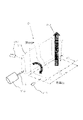
- FIG. 1 is a front view of the dehumidifier 1 of the first embodiment.
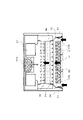
- FIG. 2 is a vertical sectional view of the dehumidifier 1 of the first embodiment.
- FIG. 2 is a cross-sectional view taken along the line AA shown in FIG.
- FIG. 3 is a horizontal sectional view of the dehumidifier 1 of the first embodiment.
- FIG. 3 is a horizontal cross-sectional view taken along the line BB shown in FIG.
- FIG. 4 is an enlarged cross-sectional view showing a part of FIG.
- the dehumidifier 1 will be described based on the state in which the dehumidifier 1 is placed on a horizontal surface such as a floor surface.
- a horizontal surface such as a floor surface.
- the surface on which the suction port 11 is present is the front surface (front surface).
- the surface on which the suction port 11 is formed is the back surface.
- the dehumidifier 1 includes a case 10.
- the case 10 constitutes a part of the housing 3 that forms the outer shell of the dehumidifier 1.
- the housing 3 has a bottom plate 4 to which a plurality of wheels 20 described later are attached.
- the case 10 and the bottom plate 4 form a hollow box-shaped housing 3.
- Wheels (casters) 20 for moving the dehumidifier 1 may be arranged one by one on the bottom plate 4 at positions separated from each other in front, back, left and right. A heavy object such as an electric compressor 6 described later is placed on the bottom plate 4. Therefore, a metal plate having a higher strength (rigidity) than the case 10 is used for the bottom plate 4.
- the case 10 is assembled into a single box shape by connecting the ends of a plurality of thin metal plates to each other with a binder such as a screw (not shown).
- a binder such as a screw
- the case 10 is assembled into a single box shape by joining a plurality of members formed by integral molding using a thermoplastic resin (plastic) material with a binder (not shown) such as a screw. It is a thing.
- the case 10 has a rear case 10B and a front case 10F.
- the rear case 10B is a member that forms the back surface portion of the case 10.
- the front case 10F is a member that forms the front surface portion of the case 10.
- the front case 10F is fixed to the rear case 10B by, for example, a connector (not shown) such as a screw.
- the upper case 10U on a flat plate is connected to the upper ends of the rear case 10B and the front case 10F.
- the upper case 10U is composed of two parts, a front part 10UF and a rear part 10UB.
- the front portion 10UF and the rear portion 10UB are in contact with each other so as to face each other from the front and back, forming one flat surface. This surface is the ceiling surface of the case 10 itself.
- a suction port 11 and an outlet 12 are formed in the case 10.
- the suction port 11 is an opening for taking in air from the outside to the inside of the case 10.
- the air outlet 12 is an opening for sending air from the inside of the case 10 to the outside.
- the suction port 11 is formed in a square window shape in the central portion of the front case 10F.
- the air outlet 12 is formed on the ceiling surface portion of the case 10. The air outlet 12 is opened by opening the entire rear portion 10UB of the upper case 10U upward to a certain angle with the front end as a fulcrum, as shown in FIG.
- the suction port 11 is square when the housing 3 is viewed from the front.
- the suction port 11 may be rectangular or circular.
- a square window formed on the front case 10F of the housing 3 may be used as it is, or a frame-shaped frame is fitted inside the window, and the inside of the frame is fitted with the suction port 11. You may use it as.
- the dehumidifier 1 includes a suction port cover 11A that covers the suction port 11.
- the suction port cover 11A is formed, for example, in a grid pattern. Alternatively, the suction port cover 11A may have a fine shutter (louver shape) as a whole.
- the suction port cover 11A prevents foreign matter from entering the inside of the case 10 through the suction port 11.
- the suction port cover 11A is detachably fixed to the rear case 10B, for example, by a fixing tool such as a screw.
- the suction port cover 11A has a "net” (net) attached to the entire surface of the suction port cover 11A to prevent foreign matter from entering.
- the suction port cover 11A may be integrally molded with a plastic material.
- the suction port cover 11A can prevent, for example, large foreign substances (such as waste paper and fiber waste such as clothing) that have risend into the air from entering the inside of the housing 3.
- the suction port cover 11A has a small pressure loss and a poor air purifying action for fine particles and the like, and is not a kind of air purifying means described later.
- the "air purifying means" in the present embodiment is an activated carbon filter 42 and a HEPA filter 41.
- reference numeral 11A1 is a vertical rail constituting the suction port cover 11A.
- reference numeral 11A2 is a cross rail constituting the suction port cover 11A.
- the vertical rails 11A1 and the horizontal rails 11A2 form a large number of ventilation windows 5 in the suction port cover 11A.
- reference numeral 6 is an electric compressor.
- the electric compressor 6 may be of any type such as a reciprocating type or a rotary type.
- the electric compressor 6 has a motor (not shown), and puts a refrigerant in a refrigerant pipe (also referred to as a “refrigerant circuit”) 22 connected to an evaporator 31 and a condenser 32, which will be described later. Forcibly circulate. That is, the electric compressor 6 compresses and supplies the refrigerant to the refrigeration cycle configured by connecting the evaporator 31, the condenser 32, and the like with the refrigerant pipe 22.
- a refrigerant pipe also referred to as a “refrigerant circuit”
- the motor of the electric compressor 6 (not shown) can change the rotation speed per unit time by the power supplied from the drive circuit 27 described later. If the rotation speed changes, the refrigerant supply capacity can be changed, and the cooling capacity can be increased / decreased (adjusted).
- the main control device 18 designates a drive frequency with respect to the drive circuit 27, and controls the rotation speed of the motor (not shown) of the electric compressor 6.
- reference numeral 7 is a water storage tank. Drain water generated on the outer surface of the evaporator 31 due to the dehumidifying operation is directly dropped and guided to the water storage tank 7. Alternatively, drain water is guided into the water storage tank 7 by a guide plate such as a gutter.
- the water storage tank 7 can be taken out of the housing 3 from the rear case 10B or the take-out port (not shown) formed on the side surface of the case 10. The outlet is covered with a door (not shown) that can be opened and closed except when the water storage tank 7 is taken out.
- the dehumidifier 1 includes a louver 13.
- the louver 13 is composed of only one rear portion 10UB of the upper case 10U as described above.
- the louver 13 may be composed of several plate-shaped members.
- the louver 13 is for adjusting the direction in which air is sent out from the outlet 12.
- the louver 13 is arranged so as to be openable and closable near the outlet 12.
- the posture of the louver 13 is changed by a connected louver drive motor (not shown).
- the louver drive motor (not shown) causes the louver 13 to change its inclination angle with respect to the outlet 12 in several steps or more. Thereby, the direction of the air (air flow AF) blown out from the air outlet 12 can be adjusted.
- the operation of the louver drive motor (not shown) is controlled by a drive signal from the control board (not shown).
- the control board (not shown) is housed in a board box 16 made of a metal plate or a nonflammable heat-resistant plastic case.
- the dehumidifier 1 includes an operation notification unit 15.
- the operation notification unit 15 includes an input operation unit 17 (see FIG. 11) and a notification unit 23 (see FIG. 11) for the user to operate the dehumidifier 1.
- the notification unit 23 displays the state of the dehumidifier 1 and the like to the user with visible information such as characters. Further, the notification unit 23 can also notify by voice.
- an operation display board 8 for controlling the operation notification unit 15 is arranged inside the case 10 facing the operation notification unit 15.
- An operation switch for starting / stopping the operation of the dehumidifier 1 is arranged on the operation display board 8.
- the operation display board 8 may be composed of two or more, an operation board 8A on which the circuit parts of the input operation unit 17 described later are mounted, and a display board 8B on which the circuit parts related to the display unit 23D are mounted. ..
- the operation display board 8 switches the operation mode to any one of three types, "dehumidifying operation mode”, “air cleaning operation mode”, and “dehumidifying air cleaning operation mode” (FIG. 6). 11).
- the operation display board 8 has a notification unit 23 (see FIG. 11) and an input operation unit 17, respectively.
- a liquid crystal display unit 23D capable of displaying information is arranged below the front portion 10UF (upper wall surface) of the upper case 10U in the operation notification unit 15.
- the display information of the display unit 23D is displayed above the upper case 10U through the front portion 10UF.
- the operating conditions, operating state, etc. of the dehumidifier 1 are displayed on the outside of the housing 3 via the display unit 23D of the operation notification unit 15.
- the operation display board 8 is horizontally arranged near the inner ceiling portion of the front case 10F.
- a power supply board (not shown) and a board box 16 containing one or several control boards are arranged.
- a drive circuit 28 for the fan 21, which will be described later, and a drive circuit (inverter circuit) 27 for the electric compressor 6 are mounted on the control board, respectively.
- a fan 21 (rotor blade) is provided at the rear part inside the case 10.
- the fan 21 is a device that takes in air inside the case 10 and sends the taken-in air to the outside of the case 10.
- the fan 21 rotates to generate an airflow AF from the suction port 11 to the air outlet 12 in the air passage from the suction port 11 to the air outlet 12.
- the motor 21A is housed inside the case 10.
- the motor 21A is a device for rotating the fan 21.
- the fan 21 and the motor 21A are arranged at the rear part of the housing 3. That is, it is arranged on the back side of the dehumidifier 1.
- the motor 21A is connected to the rotation center of the fan 21 via a rotation shaft 21b extending in the horizontal direction.
- the rotational operation of the motor 21A is controlled by a drive circuit 28 (see FIG. 11) described later. That is, the drive circuit 28 controls the start and stop of rotation and the rotation speed of the motor 21A, respectively.
- the fan 21 is a sirocco fan (multi-blade fan), and the central part of rotation is fixed by the rotating shaft 21B.
- the fan 21 sucks air into the fan case 36, which will be described later, from the front, and blows out the air from the outlet 12.
- the fan case 36 surrounds the fan 21 and the motor 21a.
- a bell mouth portion 37 is formed at a position corresponding to the fan 21 on the wall surface on the front side of the fan case 36.
- the bell mouth portion 37 has a large circular opening, and the rim portion is greatly curved to the leeward side.
- the bell mouth portion 37 is adapted to smoothly suck the air flow that has passed through the condenser 32.
- the dehumidifier 1 includes an evaporator 31, a condenser 32, an electric compressor 6 and a decompression device (not shown) as an example of a dehumidifying means for removing water contained in the air.
- the evaporator 31 and the condenser 32 form a refrigerant circuit together with the electric compressor 6 and a decompression device (not shown).
- the evaporator 31, the condenser 32, the electric compressor 6, and the decompression device are housed inside the case 10. As shown in FIG. 2, the evaporator 31 and the condenser 32 are vertically installed so as to block the front side of the bell mouth portion 37.
- the electric compressor 6 is installed at the bottom of the case 10 as shown by the broken line in FIG.
- reference numeral 38 is a flat plate-shaped rectifying member, and is entirely formed of, for example, a thermoplastic plastic material.
- the rectifying member 38 is formed with a frame 38B that intersects in the vertical direction and the horizontal direction, and a large number of ventilation windows 38A are formed between the frames 38B. There is. That is, each ventilation window 38A is an opening independent of each other.
- the ventilation window 38A is regularly arranged in the horizontal direction and the vertical direction over the entire rectifying member 38.
- the front, rear, left and right surfaces of the frame 38B are flat guide surfaces of a certain length D5 (see FIG. 4) in order to allow the airflow AF to flow linearly.
- the length D5 is set to one dimension (for example, 12 mm) in the range of, for example, 10 mm to 15 mm.
- the diameter (opening area) of the ventilation window 38A is set evenly over the entire rectifying member 38.
- the rectifying member 38 faces the front surface of the evaporator 31, which is a part of the heat exchanger described later, across the first space 33. That is, the rectifying member 38 faces the evaporator 31 at a predetermined distance D3 (see FIGS. 5 and 6).
- the rectifying member 38 faces the back surface of the activated carbon filter 42, which is a part of the air purifying filter (air purifying means) described later, with a second space 34 interposed therebetween. That is, the rectifying member 38 faces the back surface of the activated carbon filter 42 at a predetermined distance D4.
- the evaporator 31, the electric compressor 6, the condenser 32, and the decompression device (not shown) are connected in order via a refrigerant pipe (not shown) or the like.
- the refrigerant from the electric compressor 6 flows through the refrigerant circuit formed by the evaporator 31, the electric compressor, the condenser 32, and the decompression device (not shown).
- the evaporator 31 and the condenser 32 are heat exchangers for exchanging heat between the refrigerant and air.
- the electric compressor 6 described with reference to FIG. 1 is a device for compressing a refrigerant.
- the decompression device (not shown) is a device that depressurizes the refrigerant.
- the depressurizer (not shown) is, for example, an expansion valve or a capillary tube.
- the dehumidifier 1 includes a HEPA filter 41 and an activated carbon filter 42, which are air purifying filters for purifying the air, as an example of the air purifying means for removing dust and odor in the air.
- the HEPA filter 41 and the activated carbon filter 42 are housed inside the case 10.
- the HEPA filter 41 and the activated carbon filter 42 are housed inside the front case 10F between the suction port 11 and the rectifying member 38.
- the HEPA filter 41 is a filter that collects fine dust in the air.
- the activated carbon filter 42 is a filter that deodorizes the odor in the air. As described above, the activated carbon filter 42 is arranged apart from the front surface of the rectifying member 38 by a space having a predetermined distance D4 (“second space 34” described later).
- the HEPA filter 41 and the activated carbon filter 42 can be inserted to the front position of the rectifying member 38 through the suction port 11 with the suction port cover 11A removed from the front case 10F.
- the HEPA filter 41 and the activated carbon filter 42 can be detachably installed inside the case 10.
- the rectifying member 38 also serves as a protective member for preventing the user from touching the evaporator 31 when the HEPA filter 41 and the activated carbon filter 42 are removed from the rear case 10B. Therefore, even if the user's finger or the like is pressed from the front, the finger or the like does not touch the evaporator 31.
- an air passage leading from the suction port 11 to the air outlet 12 is formed inside the case 10.
- the airflow AF flowing inside the air passage flows from the suction port 11 in the order of the suction port cover 11A, the HEPA filter 41, the activated carbon filter 42, the evaporator 31, the condenser 32, and the fan 21.
- a series of air passages are formed for the air entering from the suction port 11 to flow from the heat exchanger (evaporator 31, etc.) toward the fan 21 through the air purifying filter (HEPA filter 41 and activated carbon filter 42).
- the upstream side and the downstream side are determined by using the airflow AF flowing through the air passage leading from the suction port 11 to the air outlet 12.
- the side where the suction port 11 is located is the upstream side of the heat exchanger (evaporator 31, etc.).
- the side where the outlet 12 is located is the downstream side with respect to the heat exchanger (evaporator 31, etc.).
- reference numeral 62 is a dust sensor.
- the dust sensor 62 is arranged at the top inside the case 10.
- a small-diameter opening 62A (not shown) is provided in the vicinity of the dust sensor 62 in the case 10 so that the dust sensor 62 communicates with the outside of the case 10.
- Dust detection information is acquired by the dust sensor 62 and the main control device 18 described later, and the amount and concentration of dust in the indoor space where the dehumidifier 1 is installed can be measured.
- the dust sensor 62 has, for example, the ability to detect particles of 0.1 ⁇ m.
- the detection result of the dust sensor 62 is acquired by the main control device 18, and the acquired dust detection information can be displayed on the display unit 23D arranged on the operation display board 8.
- reference numeral 63 is a gas sensor 63.
- the gas sensor 63 is arranged inside the case 10 at a position below the suction port 11.
- the wall surface of the case 10 in the vicinity of the gas sensor 63 is provided with an opening 63A (not shown) having a small diameter for communicating the outside of the case 10 with the gas sensor 63.
- Gas detection information is acquired by the gas sensor 63 and the main control device 18, and the odor of the air in the room can be measured.
- the measurement result of the gas sensor 63 is acquired by the main control device 18, and the acquired gas detection information can be displayed on the display unit 23D arranged on the operation display board 8.
- reference numeral 26 is a wireless communication unit (wireless communication module) housed near the ceiling inside the case 10.
- the wireless communication unit 26 can perform wireless communication with a local network facility such as a wireless router (not shown) installed in the home or office where the dehumidifier 1 is located.
- the wireless communication unit 26 may be connected to an Internet line (not shown) via a local network facility.
- the wireless communication unit 26 can exchange information with information processing terminals (not shown) such as smartphones and other communication devices at remote locations via the Internet line.
- the local network equipment may be a command device that controls the total power consumption in the home or the office, or an integrated management device that collects and links information on a plurality of electric devices, and may be "access”. Sometimes called "point".
- the rotating shaft 21B of the motor 21A extends in the horizontal direction.
- the HL is a horizontal center line that penetrates the center of the rotation shaft 21B.
- the position of the center line HL is at the center of the suction port 11 in the vertical direction. That is, the rotating shaft 21B exists at a position at a height of half of the suction port 11 having a height dimension of H1.
- FIG. 3 there are bypass air passages 43 adjacent to each other on the left and right sides of the HEPA filter 41 and the activated carbon filter 42.
- the bypass air passage 43 is a space provided inside the front case 10F over the entire height direction of the suction port 11.
- the bypass air passage 43 is an air passage extending rearward from the suction port 11. In other words, it is a narrow passage extending in the direction from the front.
- reference numeral 46 is a wind tunnel extending rearward from the mouth edge portion of the suction port 11.
- the wind tunnel 46 is entirely formed of a member made of thin sheet metal or a member made of thermoplastic plastic.
- the gap between the front end of the wind tunnel 46 and the left and right sides of the HEPA filter 41 is the entrance 43A of the bypass air passage 43.
- the rear end portion of the wind tunnel 46 comes into contact with the outer peripheral end portion of the rectifying member 38 so that the airflow AF does not leak to the outside on the way.
- the gap between the rear end of the wind tunnel 46 and the left and right sides of the activated carbon filter 42 is the outlet 43B of the bypass air passage 43.
- the air passage leading from the suction port 11 to the air outlet 12 is composed of two air passages, a main air passage 44 and a bypass air passage 43.
- the main air passage (also referred to as “first air passage”) 44 is an air passage that passes from the suction port 11 through the HEPA filter 41 and the activated carbon filter 42 to the rectifying member 38.
- the bypass air passage (also referred to as “second air passage”) 43 is an air passage from the suction port 11 to the rectifying member 38 without passing through the HEPA filter 41 and the activated carbon filter 42.
- W5 is the frontage dimension of the suction port 11. In other words, it is the width dimension. In the first embodiment, W5 is 315 mm.
- the HL in FIG. 3 is a center line penetrating the center of the rotating shaft 21B of the motor 21A.
- reference numeral 51 is an airflow limiting means for opening / closing operation for substantially opening / closing the inlet 43A of the bypass air passage 43 to limit the flow of the bypass airflow AF2.
- the airflow limiting means 51 are arranged on the left and right sides of the suction port 11, and will be described in detail with reference to FIG.
- FIG. 4 is an enlarged cross-sectional view of the E portion of FIG.
- the bypass air passage 43 is an air passage in which the airflow AF flows downstream without passing through the HEPA filter 41 and the activated carbon filter 42.
- the main air passage 44 is the air passage through which the airflow AF passes through the HEPA filter 41 and the activated carbon filter 42 with respect to the bypass air passage 43.
- the bypass air passage 43 is formed on the right side and the left side of both the HEPA filter 41 and the activated carbon filter 42, respectively. That is, the bypass air passage 43 and the main air passage 44 are adjacent to each other and are arranged in parallel in the front-rear direction.
- bypass airflow the airflow passing through the bypass air passage 43
- main airflow the airflow passing through the main airflow passage 44
- the bypass air passage 43 which is an air passage that does not pass through the air purification filter
- the main air passage 44 which is an air passage that passes through the air purification filter
- the air passage in the dehumidifier 1 can be compactly configured, and the dehumidifier 1 can be miniaturized.
- the height dimension of the bypass air passage 43 in the vertical direction (vertical direction) is set to be about the same as the length of the HEPA filter 41 in the vertical direction (vertical direction). Is desirable.
- bypass airflow AF2 flowing through the bypass airflow passage 43 and the main airflow AF1 flowing through the main air passage 44 are rectified with the space downstream of the activated carbon filter 42, that is, the first space 33 separated by a distance D3 from the rectifying member 38 as a starting point. It merges with a second space 34 having a distance D4 starting from the member 38.
- bypass airflow AF2 and the main airflow AF1 merge in front of the evaporator 31 arranged downstream of the activated carbon filter 42, and then flow in one air passage inside the case 10.
- main airflow AF1 flowing in the main air passage 44 the main airflow AF1 that has passed through the portion near the left and right ends of the activated carbon filter 42 passes through the left and right ends of the rectifying member 38 immediately after passing through the activated carbon filter 42. When doing so, it merges with the bypass airflow AF2.
- the first space 33 and the second space 34 are provided, but it is sufficient that the airflow flowing through the bypass air passage 43 and the main air passage 44 can be merged in front of the evaporator 31. Therefore, it suffices if there is at least the first space 33. If the first space 33 cannot be secured with a sufficient size, the second space 34 may be provided. For example, when it is assumed that the HEPA filter 41 and the activated carbon filter 42, which have received the air resistance when the main airflow AF1 passes through, move or bend to the downstream side and come into contact with the rectifying member 38. It is preferable to provide a second space 34.
- a wind guide surface 46A is formed on the downstream side of the bypass airflow AF2 in the wind tunnel 46.
- the wind tunnel 46 is provided with a pair of left and right wind guide surfaces 46A at positions connected to the rectifying member 38.
- the air guide surface 46A is inclined symmetrically (at the same angle) so as to approach the HEPA filter 41 and the activated carbon filter 42 when viewed in a plane.
- the wind guide surface 46A is for guiding the bypass airflow AF2 that has passed through the bypass air passage 43 toward the center of the windward front surface of the heat exchanger (evaporator 31, etc.).
- the center line HL side penetrating the center of the rotation shaft 21B of the motor 21A has a function of slightly changing the traveling direction of the bypass airflow AF2.
- the wind guide surface 46A shown in FIG. 4 is entirely composed of one flat inclined surface. By adjusting the normal direction (inclination angle) of this inclined surface, the direction in which the bypass airflow AF2 is guided can be adjusted. Since the wind guide surface 46A is composed of one surface having no uneven portion in the middle, the resistance when the bypass airflow AF2 flows is small, and unnecessary turbulence is not generated.
- the wind guide surface 46A may be configured with a curved surface. By adjusting the curvature of the curved surface, the spread of the bypass airflow AF2 guided by the wind guide surface 46A can be adjusted. In this way, in a part of the second air passage (bypass air passage 43), the bypass airflow AF2 is placed in a predetermined direction (in FIG. 3, the center line HL) on the wind side of the heat exchanger (evaporator 31, etc.). Since the air guide surface 46A leading to the direction) is provided, the bypass airflow AF2 passing through the bypass air passage 43 can be efficiently flowed into the heat exchanger, and the dehumidification efficiency can be improved.
- the bypass air passage 43 is provided with an air flow limiting means 51.
- the airflow limiting means 51 has a plate-shaped flap or a partition plate that opens and closes the inlet 43A of the bypass air passage 43. This flap or partition plate is collectively referred to as a shutter 51S.
- the shutter 51S is arranged on the downstream side of the suction port cover 11A. One end of the shutter 51S is pivotally supported by a rotating shaft 51E (see FIG. 10).
- the shutter 51S is fixed at an open position and a closed position by a driving motor 51B (see FIG. 10) that serves as an opening / closing means, and also maintains a stopped state at a specific position between the open position and the closed position.
- the airflow limiting means 51 has a function of determining whether or not the bypass airflow AF2 flows in the bypass air passage 43, and a function of adjusting the amount of the bypass airflow AF2 flowing in the bypass air passage 43.
- FIG. 5 is a view in which dimensions are added to the same cross-sectional view as in FIG. D1 indicates the thickness (depth dimension) of the condenser 32 in the front-rear direction, and is 51 mm.
- D2 indicates the thickness (depth dimension) of the evaporator 31 in the front-rear direction, and is 38 mm.
- Refrigerant pipes 22 are arranged in two rows (two layers) in the front-rear direction of the evaporator 31. Since the refrigerant pipes 22 are provided in two layers as described above, the cooling capacity is higher than that of one layer.
- the evaporator 31 and the condenser 32 are not drawn in a size proportional to the actual thickness, but are drawn in the same size in these figures. ..
- the counter interval D4 is the facing distance (distance) between the activated carbon filter 42 and the rectifying member 38, which is 15 mm. It should be noted that the counter interval D4 does not always have to be completely the same over the entire rectifying member 38. When the activated carbon filter 42 is partially curved to the downstream side due to the passage of the airflow AF, the counter interval D4 may be slightly smaller in that portion.
- D3 is a counter distance (distance) between the rectifying member 38 and the evaporator 31, and is 10 mm. As shown in FIG. 7, in the evaporator 31, innumerable thin metal plates 31F for heat exchange called plate fins are arranged at a minute interval (pitch) of 1 mm or less and penetrate them. A refrigerant pipe 22 is arranged in the water.
- the counter spacing D3 is the spacing between the thin plate 31F and the rectifying member 38.
- W1 is a substantial width dimension of the main air passage 44 excluding the portion closed by the airflow limiting means 51 from the width dimension (frontage dimension) of the suction port 11, and is set to 255 mm.
- W5 is the width dimension (frontage dimension) of the suction port 11 and is set to 315 mm.
- FIG. 6 is a cross-sectional view at the same position as in FIG. 5, which is a diagram in which the main parts are virtually separated and the dimensions of each part are clarified.
- W2 is the width dimension of the evaporator 31 and is set to 270 mm.
- W3 is the width dimension of the condenser 32 and is set to 270 mm.
- W4 is the diameter of the opening of the bell mouth portion 37, and is set to 230 mm.
- BL is a horizontal reference line extending in the front-rear direction through the center points (up / down / left / right) of the opening of the bell mouth portion 37.
- W6 is the width dimension of the window 47A of the rear wind tunnel 47 (see FIG. 4) that surrounds the left and right sides of the rectifying member 38, and is set to 270 mm.
- a rectifying member 38 is fitted in the window 47A.
- H2 is the height dimension of the window 47A of the rear wind tunnel 47.
- the height dimension H2 is 252 mm, which is the same as the height dimension H3 of the evaporator 31.
- each of the condenser 32 and the evaporator 31 is 270 mm.
- the condenser 32 and the evaporator 31 are arranged close to each other in the front-rear direction, and when viewed from the front, they appear to be overlapped at the same position.
- the width dimension W6A of the rectifying member 38 is also a dimension close to 270 mm of the dimension W6 because it fits into the window 47A.
- the three parts of the rectifying member 38, the evaporator 31, and the condenser 32 are arranged in a line in the front-rear direction according to the position of the window 47A of the rear wind tunnel 47.
- the three parts of the rectifying member 38, the evaporator 31, and the condenser 32 are arranged in a row in the front-rear direction according to the reference line BL.
- the rectifying member 38, the evaporator 31, the condenser 32, and the bell mouth portion 37 are arranged so as to overlap each other on one straight line (reference line BL).
- both the HEPA filter 41 and the activated carbon filter 42 are in a positional relationship in which they overlap in a straight line on the reference line BL. Therefore, the airflow FA sucked from the suction port 11 flows linearly from the front to the rear within the range centered on the reference line BL regardless of whether it passes through the bypass air passage 43 or the main air passage 44.
- the air passage resistance is small and the operating efficiency can be improved.
- the horizontal reference line BL is a straight line penetrating the center point of the opening of the bell mouth portion 37, and at the same time, a straight line penetrating the center points of the HEPA filter 41 and the activated carbon filter 42. But it is also. Therefore, the reference line BL is also referred to as the center line of the air purifying means (HEPA filter 41 and activated carbon filter 42).
- the reference line BL is at a position coincided with the center line HL penetrating the center of the rotation shaft 21B.
- the rectifying member 38, the evaporator 31, the condenser 32, the HEPA filter 41, and the activated carbon filter 42 have their respective central portions on the reference line BL.
- the HEPA filter 41 and the activated carbon filter 42 are arranged so as to be symmetrical with respect to the reference line BL.
- FIG. 7 is a simplified perspective view of the evaporator 31.
- FIG. 7 shows the relationship between the width dimension W6 and the like of the rectifying member 38 and the evaporator 31.
- W2 is the width dimension of the evaporator 31 and is set to 270 mm as described above.
- the refrigerant pipe 22 penetrates the inside of the evaporator 31 in two front and rear stages (two layers). The refrigerant pipe 22 penetrates from the first predetermined position of the evaporator 31 to the second predetermined position while meandering. A part of the refrigerant pipe 22 protrudes in a bent shape as shown in FIG. 7 on the way.
- the protrusion amount L2 of the refrigerant pipe 22 shown in FIG. 7 is 14 mm on the right side of the evaporator 31, but 26 mm on the left side.
- the height dimension H3 of the evaporator 31 is 252 mm.
- the width dimension W6 of the window 47A of the rear wind tunnel 47 surrounding the left and right sides of the rectifying member 38 is set to 270 mm as described above.
- the OB is a center point (second center point) on the left, right, top and bottom when the evaporator 31 is viewed from the front.
- CL1 is a horizontal center line that horizontally crosses the second center point OB of the evaporator 31.
- CV1 is a vertical centerline that vertically crosses the second center point OB of the evaporator 31.
- D2 is the depth dimension of the evaporator 31, which is 38 mm as described above.
- FIG. 8 is a perspective view illustrating the sizes of both the HEPA filter 41 and the activated carbon filter 42 constituting the air purifying means.
- the activated carbon filter 42 is composed of a filter main body 42A that exhibits a function of collecting dust and adsorbing odorous components, and a frame body 42B that protects the entire peripheral edge of the filter main body 42A.
- the filter body 42A itself is flexible, it is integrated with the frame body 42B to provide a certain degree of rigidity, which makes it easy for the user to handle the filter body 42A even when performing replacement work.
- W8 is the width dimension of the frame body 42B and is set to 255 mm. That is, the width dimension W8 of the frame body 42B is set to be substantially the same as the width dimension W1 (255 mm) of the main air passage 44 as described with reference to FIGS. 5 and 6.
- H4 is the height dimension of the frame body 42B and is set to 252 mm. That is, it has the same size as the (inside) height dimension H2 of the window 47A of the rear wind tunnel 47 described with reference to FIG. 7. Further, the height dimension H4 is the same as the height dimension H3 of the evaporator 31.
- D6 is the depth dimension of the frame body 42B. In other words, it is the "thickness" when viewed from the left-right direction, and is set to one dimension (for example, 10 mm) from 5 mm to 15 mm.
- the filter main body 42A has the same depth dimension as the frame body 42B.
- the depth dimension of the activated carbon filter 42 is determined by the depth dimension D6 of the frame body 42B. When the frame body 42B is viewed from the front, the thickness of the frame body 42B alone is about several mm.
- the HEPA filter 41 is composed of a filter main body 41A that exerts a dust collecting function and a frame body 41B that protects the entire peripheral edge of the filter main body 41A.
- the filter body 41A itself is flexible, it is integrated with the frame body 41B to provide a certain degree of rigidity, which makes it easy for the user to handle the filter body 41A even when the replacement work is performed.
- W9 is the width dimension of the frame body 41B and is set to 255 mm. That is, the width dimension W9 of the frame body 41B is set to be substantially the same as the width dimension W1 (255 mm) of the main air passage 44 as described with reference to FIGS. 5 and 6.
- H5 is the height dimension of the frame body 41B and is set to 252 mm. That is, it has the same size as the (inside) height dimension H2 of the window 47A of the rear wind tunnel 47 described with reference to FIG. 7. Further, the height dimension H5 is the same as the height dimension H3 of the evaporator 31.
- D7 is the depth dimension of the frame body 41B. In other words, it is the "thickness" when viewed from the left-right direction, and is set to one dimension (for example, 30 mm) within 20 mm to 40 mm.
- the filter main body 41A has the same depth dimension as the frame body 41B.
- the depth dimension of the HEPA filter 41 is determined by the depth dimension D7 of the frame body 41B. When the frame body 41B is viewed from the front, the thickness of the frame body 41B alone is about several mm.
- FIG. 9 is a dimensional explanatory view of the suction port 11 portion when the dehumidifier 1 of the first embodiment is viewed from the front side.
- FIG. 9 is a front view at the same position as FIG. 1, but the size of the suction port 11 and the like is shown by a broken line frame in order to display the dimensional relationship.
- CL1 is a horizontal center line that crosses the center point (first center point) OA of the suction port 11 when the case 10 is viewed from the front.
- CV2 is a vertical center line penetrating the center point (first center point) OA of the suction port 11.
- H1 is a substantially maximum dimension of the suction port 11 in the height direction, which is 270 mm.
- W1 is a substantially lateral width dimension of the main air passage 44, and is set to 255 mm.
- W5 is the width dimension (frontage dimension) of the suction port 11 and is set to 315 mm.
- W7 is the width dimension of the inlet portion of the bypass air passage 43 provided on the left and right sides of the suction port 11, and each is set to 30 mm.
- the position of the first center point OA in FIG. 9 and the position of the second center point OB in FIG. 7 are the same positions that completely overlap when viewed from the front.
- the second center point OB is located on a horizontal straight line that penetrates the first center point OA from the front.
- FIG. 10 is a schematic diagram illustrating the operation of the airflow limiting means 51 of the first embodiment.
- One end of the flap-shaped or flat plate-shaped shutter 51S is supported by the rotating shaft 51E of the motor 51B (for example, a stepping motor).
- the shutter 51S is in the “open position” OP laterally retracted from the bypass air passage 43 as shown by the broken line.
- the shutter 51S moves to a position (closed position CL) where the bypass air passage 43 having a height dimension of H1 (270 mm) and a width dimension of the inlet 43A of W7 (30 mm) is closed. That is, when it moves to the maximum, the closed state is maintained at the closed position CL.
- the shutter 51S is not required to completely close the inlet 43A of the bypass air passage 43 in the closed position CL. Even if a minute gap is generated around the shutter 51S at the closed position CL, it does not pose a problem in the basic performance of the dehumidifier 1.
- a sealing member made of an elastic silicone rubber material or the like may be provided at the inlet 43A so that the shutter 51S is in close contact with the sealing member to improve the airtightness at the time of closing.
- reference numeral 51C and reference numeral 51D are sensors that electrically detect that the shutter 51S is in the open position OP and the closed position CL.
- the sensors 51C and 51D are, for example, an optical sensor such as infrared rays or a magnetic detection sensor.
- the detection signals of the sensors 51C and 51D are input to the open / close detection unit 53, and finally input to the main control device 18 described later as open / close detection signals (see FIG. 11).
- FIG. 11 is a block diagram showing main control-related components of the dehumidifier 1 of the first embodiment.
- the sensors 51C and 51D described with reference to FIG. 10 are not shown.
- the main control device 18 has a function of controlling the entire dehumidifier 1.
- the main control device 18 includes an electronic circuit board on which electronic components such as a drive circuit, a power supply circuit, and a sensor that control the operation of each part constituting the dehumidifier 1 are mounted, and a microcomputer and the like mounted on the electronic circuit board. It is equipped with a CPU (central processing unit) 24 and a storage device such as a ROM and a RAM.
- the CPU 24 is provided with a timer unit 24T for exerting a time measurement function such as an operating time.
- the main control device 18 receives an input command signal corresponding to the operation of the input operation unit 17, and emits a command signal to the drive circuit (inverter circuit) 27 of the electric compressor 6. Further, a command signal is issued to the drive circuit 28 to control the operation of the motor 21A of the fan 21. Further, the main control device 18 issues a command signal to the drive circuit 29 for controlling the airflow limiting means 51.
- the main control device 18 issues command signals for transmitting and receiving information to the wireless communication unit 26. Further, when the wireless communication unit 26 is not always used, a command signal for stopping the supply of power to the wireless communication unit 26 and a command signal for starting the supply of the power are also issued.
- control device 18 when the main control device 18 receives a user's command from the input operation unit 17, it issues a command to connect to an Internet line (not shown) via a local network facility described later, and is required from the outside. In some cases, "control data” and “notification data” (these will be described later) are acquired.
- the main control device 18 is a drive circuit (inverter circuit) 27 and a drive circuit of the airflow limiting means 51. 29 and 29 are controlled respectively.
- the airflow limiting means 51 that receives a drive command from the drive circuit 29 includes a shutter 51S (see FIG. 10), a motor 51B, and the like.
- the input operation unit 17 has an operation mode changeover switch 17S.
- the notification unit 23 has a display unit 23D and a voice notification unit 23V.
- the main control device 18 includes various "operation programs” used for controlling the dehumidifier 1, data such as parameters (hereinafter, these are collectively referred to as “control data”), a display unit 23D, and a voice notification unit 23V. It has a storage means 25 for storing display data for a display screen and data for voice notification (hereinafter, these are collectively referred to as “notification data”) used for the display screen.
- control data data such as parameters
- a display unit 23D a display unit 23D
- voice notification unit 23V voice notification unit
- the above “operation program” is also referred to as a control program, but hereinafter, it is collectively referred to as a "program”.
- the main control device 18 plays the role of a host computer (main computer) that integrally controls the entire dehumidifier 1.
- main computer main computer
- a "slave microcomputer”) may be further provided. Then, the sub-control device may be in charge of information processing of the input operation, notification, and drive control of the electric compressor 6.
- each component of each circuit, component, and device shown in FIG. 11 is a functional concept, and may not necessarily be physically configured as shown in the figure.
- the functions of each of these circuits can be distributed and integrated, and the specific form is not limited to that shown in the figure. All or part of each function can be functionally or physically distributed and integrated in any unit according to the function, operating conditions, and the like.
- Each function of the timer unit 24T, the drive circuit 29, and the open / close detection unit 53 is realized by the processing circuit.
- the processing circuit that realizes each function may be dedicated hardware, or may be one or a plurality of processors that execute a program stored in the storage means 25.
- the detection data of various sensors such as the room temperature sensor 35, the dust sensor 62, the temperature sensor for monitoring the temperature of the important part of the dehumidifier 1 (for example, the electric compressor 6) and the gas sensor 63 are concentrated.
- a dedicated processing unit for collecting and determining the suitability of the operating state, the presence or absence of an abnormality, and the like may be provided, and the determination signal from the processing unit may be input to the main control device 18.
- the processing unit may be dedicated hardware or may be realized by a processor that executes a program stored in the storage means 25.
- each function of the main control device 18 is realized by software, firmware, or a combination of software and firmware.
- the software and firmware are described as a program and stored in a storage means 25 which is a memory.
- the CPU (processor) 24 realizes each function of the main control device 18 by reading and executing a program stored in the storage means 25.
- the storage means 25 is typically a non-volatile or volatile semiconductor memory such as RAM, ROM, flash memory, EPROM, or EEPROM.
- a part of the data and the program of the storage means 25 may be held in an external recording medium (storage server or the like) without being held by the dehumidifier 1.
- the dehumidifier 1 acquires necessary data and program information by accessing an external recording medium (storage server) via wireless communication or wire via the wireless communication unit 26.
- the operation programs of the main control device 18, the input operation unit 17, the notification unit 23, etc. may be updated to those appropriately improved at the request of the user, the manufacturer of the dehumidifier 1, or the like.
- the dehumidifier 1 may obtain the modification program through the wireless communication unit 26.
- the dehumidifier 1 has a humidity sensor 61 (see FIG. 3).
- the humidity sensor 61 is arranged inside the case 10.
- An opening (not shown) for communicating the humidity sensor 61 with the outside of the case 10 is provided in the vicinity of the humidity sensor 61 of the case 10.
- Humidity detection information is acquired by the humidity sensor 61 and the main control device 18, and the humidity in the room can be measured.
- the measurement result of the humidity sensor 61 is displayed by the display unit 23D that receives the display command from the main control device 18.
- reference numeral 19 is a power supply unit that receives AC power from the commercial power supply 40 and supplies power of a predetermined voltage to each portion.
- the power supply unit 19 receives power of 200V or 220V, 50Hz or 60Hz from the commercial power supply 40, converts it into AC power or DC power of a plurality of voltages such as 5V, 15V, 220V, and converts it into AC power or DC power of the main control device 18. It supplies power to the drive circuit 27, the notification unit 23, the drive unit 29, and the like.
- the input operation unit 17 is provided with a power switch operation button (not shown) that allows the user to open / close (ON-OFF) the main power switch (not shown) between the power supply unit 19 and the commercial power supply 40. Has been done.
- reference numeral 13A is a drive circuit for opening and closing the louver 13 provided on the ceiling of the case 10
- reference numeral 13M is a motor for opening and closing the louver 13 by receiving electric power from the drive circuit 13A. ..
- FIG. 12 is a flowchart showing an operation step during the dehumidifying operation of the dehumidifier 1 of the first embodiment.
- FIG. 13 is a flowchart showing an operation step of the dehumidifier 1 of the first embodiment during the air cleaning operation.
- FIG. 14 is a flowchart showing an operation step during the dehumidifying air cleaning operation of the dehumidifier 1 of the first embodiment.
- the main control device 18 controls the drive motor (not shown) of the compressor 6 and the drive motor 13M and the motor 21A of the louver 13 to all stop. That is, power is not supplied to the drive motor (not shown) of the compressor 6, the motor 13M, and the motor 21A.
- louver 13 and the shutter 51S are maintained in a closed state with the outlet 12 and the inlet 43A of the bypass air passage 43, respectively.
- the “dehumidifying operation mode” is an operation mode for dehumidifying the room.
- the user can start the operation of the dehumidifier 1 by turning on the operation switch (main power switch) of the input operation unit 17 and activating the main control device 18.
- the dehumidifier 1 starts the dehumidifying operation by the steps as shown below.
- the main control device 18 starts energizing the motor 13M for driving the louver so that the louver 13 opens the outlet 12, and controls the open position of the louver 13 (step S001).
- the motor 13M rotates in a predetermined direction by a fixed angle in response to a drive signal from the drive circuit 13A.
- the mechanical structure inside the motor 13M enables highly accurate positioning even with open loop control.
- the motor 13M moves at a step angle according to the number of pulses from the drive circuit 13A. This allows the louver 13 to remain open to a specified angle (eg, 45 degrees, 60 degrees or 75 degrees).
- the main control device 18 issues a command signal to the drive circuit 29 so that the shutter 51S opens to the open position OP (see FIG. 10), and supplies drive power to the motor 51B to control the open position.
- the shutter 51S rotates in a predetermined direction by a fixed angle in response to the drive signal from the drive circuit 29. By this rotational operation, the inlet 43A of the bypass air passage 43 is opened (step S002).
- the fact that the drive command is issued from the main control device 18 to the drive circuit 29 is also transmitted by a signal to the open / close detection unit 53 as shown by the broken line arrow in FIG.
- the sensors 51C and 51D are activated from the time when the open / close detection unit 53 receives the signal.
- one of the sensors corresponding to the closed position CL detects that the shutter 51S changes from "existing state” to "non-existing state” at a predetermined position.
- the other sensor corresponding to the open position OP detects that the shutter 51S changes from "non-existent state” to "existing state” at a predetermined position. As a result, the main control device 18 can determine that the shutter 51S has reliably opened the bypass air passage 43.
- the shutter 51S rotates in a predetermined direction by a fixed angle in response to the drive signal from the drive circuit 29. Therefore, the open / close detection unit 53 and the sensors 51C and 51D may be omitted.
- the opening / closing operation of the shutter 51S which is related to the basic function of the dehumidifier 1, is emphasized, and the opening / closing detection is performed so that safe operation can be performed even if there is any defect in the opening / closing operation.
- a unit 53 and sensors 51C and 51D are provided.
- the main control device 18 determines the open state of the shutter 51S in step S002, then drives the motor 21A to rotate, and controls the fan 21 to rotate at a preset strong rotation speed (step). S003). Further, the drive motor (not shown) of the electric compressor 6 is controlled to be driven. As a result, the electric compressor 6 starts the compression operation of the refrigerant (step S004).
- the main control device 18 grasps the humidity by using the humidity sensor 61.
- the humidity sensor 61 starts the humidity detection operation of the air around the humidity sensor 61, and transmits the detection data to the main control device 18. Thereby, in the main control device 18, it is determined whether the humidity is 50% or more (step S005).
- the driving operation of the driving motor of the electric compressor 6 is continuously performed to perform the dehumidifying operation (S006), and after a certain period of time, the process returns to step S005.
- the main control device 18 controls to stop the driving of the driving motor of the electric compressor 6, and the refrigerant compression operation of the electric compressor 6 is stopped. (Step S007). At this time, the main control device 18 controls to continue the rotational drive operation of the motor 21A of the fan 21, and returns to step S005 after a certain period of time.
- the humidity detection threshold value of the humidity sensor 61 is set to 50%, but the threshold value may be any other value.
- the “air purification operation mode” is an operation mode for purifying the indoor air. For example, when the user turns on the main power switch of the input operation unit 17 and selects the air cleaning operation mode with the operation mode changeover switch 17S, the dehumidifier 1 starts the air cleaning operation in the following steps.
- the main control device 18 transmits a start signal to the drive circuit 13A so that the louver 13 opens the outlet 12, and starts the operation of the motor 13M for driving the louver. Then, the louver 13 is released to a predetermined position (step S101).
- the main control device 18 rotationally drives the motor 21A and controls the fan 21 to rotate at a preset strong rotation speed (step S102).
- the main control device 18 issues a measurement command to the dust sensor 62 and the gas sensor 63.
- the dust sensor 62 and the gas sensor 63 start detecting dust and gas in the air around the sensor, respectively, and transmit the dust sensor 62 to the main control device 18.
- the main control device 18 determines the magnitude of air pollution from the acquired data (step 103).
- step S103 If it is determined in step S103 that the degree of air pollution is small, the main control device 18 rotates the fan 21 operated at a preset strong rotation speed at a preset weak rotation speed. Therefore, a command to change the rotation speed is issued to the drive circuit 28.
- the drive circuit 28 controls to reduce the rotation speed of the motor 21A per unit time (step S104), performs an air cleaning operation (weak) (step S105), and returns to step S103 after a certain period of time.
- step S103 when it is determined in step S103 that the degree of air pollution is large, the main control device 18 is operated at a high rotation speed from the stage of step S102, so that the operation of the strong operation.
- the air cleaning operation (strong) is continuously performed (step S106). That is, the drive circuit 28 is returned to step S103 after a certain period of time without issuing a command to change the rotation speed.
- the dehumidifying air cleaning operation mode switches the operation mode of the dehumidifier 1 to a dehumidifying operation mode, an air cleaning operation mode, or the like, depending on the humidity in the room or the state of air pollution. For example, when the user turns on the main power switch of the input operation unit 17 and selects the dehumidifying air cleaning operation mode with the operation mode changeover switch 17S, the dehumidifier 1 starts the dehumidifying air cleaning operation as follows.
- the main control device 18 issues a drive command to the drive circuit 28, and controls the louver drive motor 13M so that the louver 13 opens the outlet 12 (step S201).
- the main control device 18 issues a drive command to the drive circuit 29 so that the shutter 51S opens, and controls the motor 51B for opening and closing the shutter 51S.
- the inlet 43A of the bypass air passage 43 is opened (step S202).
- the main control device 18 determines that the shutter 51S has been opened to a predetermined position, the main control device 18 issues a predetermined drive command to the drive circuit 28 in order to rotationally drive the motor 21A.
- the drive circuit 28 controls the rotation speed of the motor 21A so that the fan 21 rotates at a preset strong rotation speed (step S203).
- the main control device 18 starts the operation of the motor 6M (not shown) for driving the electric compressor 6 and controls the motor 6M to be driven at a predetermined rotation speed.
- the electric compressor 6 starts the compression operation of the refrigerant (step S204).
- the humidity sensor 61 starts the humidity detection operation of the air around the humidity sensor 61, and transmits the humidity detection data to the main control device 18.
- the main control device 18 determines whether or not the humidity is 50% or more (step S205).
- step S206 When the humidity is 50% or more, the driving operation of the motor 6M (not shown) for driving the electric compressor 6 is continued.
- the dust sensor 62 and the gas sensor 63 start a detection operation of dust and gas in the air around each sensor, and determine the degree of air pollution (step S206). If the degree of air pollution is small, the operations of steps S202, S203, and S204 are continued to perform the dehumidifying operation (step S207). Then, after a certain period of time has elapsed from step S206, the process returns to step S205.
- the main control device 18 controls the motor 51B for driving the airflow limiting means 51 so as to close the shutter 51S. Then, the inlet 43A of the bypass air passage 43 is closed (step S208), the dehumidifying air cleaning operation "strong" is performed (step S209), and after a certain period of time has elapsed from step S206, the process returns to step S205.
- step S205 when the humidity is 50% or less, the main controller 18 controls to stop the driving of the motor 6M for driving the electric compressor 6, and the refrigerant compression operation of the electric compressor 6 is stopped (step S210). ).
- the main control device 18 controls the dust sensor 62 and the gas sensor 63 to start the detection operation of the dust and gas in the air around each sensor, and determines the size of the air pollution (the size of the air pollution is determined). Step S211).
- step S212 When the degree of air pollution is small, the motor 21A is controlled so that the fan 21 rotates at a preset weak rotation speed (step S212), and a circulate operation is performed only by blowing air without dehumidification (step S213). ), After a certain period of time, the process returns to step S205.
- the main control device 18 issues a closing command signal to the drive circuit 29 so as to close the shutter 51S.
- the drive circuit 29 starts the operation of the drive motor 51B and moves the shutter 51S to the closed position CL.
- step S214 the inlet 43A of the bypass air passage 43 is closed (step S214).
- the fan 21 maintains the "strong operation” mode of step S203 and performs the air-clearing operation "strong" (step S215).
- step S215 the process returns to step S205 in the dehumidifying operation mode of FIG.
- the humidity threshold value of the humidity sensor 61 in step S205 is set to 50%, but the threshold value may be any other value.
- the airflow limiting means 51 for opening and closing the inlet 43A of the bypass air passage 43 is provided, an appropriate air passage for performing the dehumidifying operation and the air cleaning operation can be provided for the bypass air passage 43 and the main air passage 44.
- a dehumidifier 1 that can be easily selected from any of them and is easy to use can be obtained.
- FIG. 15 is a flowchart showing a basic operation step of the main control device 18 at the start of operation of the dehumidifier 1 of the first embodiment.
- the main power switch (not shown) is turned on by the input operation unit 17, and the operation mode changeover switch 17S is operated. In this way, an operation mode such as "dehumidifying operation” or "air cleaning operation” is selected.
- the main control device 18 is started to be supplied with electric power as a power source from the power supply unit 19.
- the main control device 18 checks whether or not there is an abnormality in its internal configuration. Then, if there is no abnormality in the initial abnormality determination, a command signal for opening the louver 13 is emitted to the drive circuit 13A (step S300).
- step S300 the louver 13 is quickly rotated to a predetermined open position by the motor 13M. Further, the main control device 18 issues an release command signal for the shutter 51S to the drive circuit 29. Then, the timer unit 24T starts the measurement of the elapsed time from this point in time (step S301).
- the motor 51B of the airflow limiting means 51 is started to be driven by the drive circuit 29.
- the shutter 51S is rotated by the motor 51B to the open position OP by a range of about 90 degrees around the shaft 51E. As a result, the inlet 43A of the bypass air passage 43 is opened.
- the main control device 18 waits for the arrival of the opening detection signal from the open / close detection unit 53, and determines whether or not the inlet 43A of the bypass air passage 43 has been opened (step S302). If the determination result in step S302 is "Yes”, a command signal for starting ventilation is issued to the drive circuit 28.
- the command regarding the blowing strength in this case is “strong”, and the operation of the fan 21 is started in the "strong” operation mode defined by the rated blowing capacity (step S303).
- step S304 if the elapsed time from step S301 does not exceed the predetermined "reference response time" (for example, 10 seconds), the process returns to step S302 again and the open / close detection signal from the open / close detection unit 53 is detected. Judgment of opening / closing presence / absence is made based on.
- the predetermined "reference response time” for example, 10 seconds
- step S304 If the elapsed time from step S301 exceeds the "reference response time" (for example, 10 seconds) in the process of step S304, it is determined that an abnormality has occurred in the airflow limiting means 51 for some reason, and the notification unit 23 is determined. Notifies that the shutter 51S does not open. For example, the display unit 23D notifies by characters or figures. In addition, the voice notification unit 23V provides voice notification such as "Bypass air passage does not open properly". Then, after a certain period of time has elapsed (for example, after 30 seconds) from the time of these notifications, the main power switch is automatically turned off and the operation is automatically terminated (step S305).
- the "reference response time” for example, 10 seconds
- step S305 the notification unit 23 notifies only the operation that does not use the bypass air passage 43, and if no input is made from the input operation unit 17 after that, it is as in step S305.
- the power may be turned off automatically.
- FIG. 16 is a vertical cross-sectional view showing the air flow of the dehumidifier 1.
- FIG. 17 is a horizontal sectional view showing the air flow during the dehumidifying operation of the dehumidifier 1.
- FIG. 18 is a horizontal sectional view showing the flow of air during the air cleaning operation of the dehumidifier 1.
- the arrows in FIGS. 17 to 18 indicate the air flow (air flow AF) when the dehumidifier 1 is operating.
- the motor 21A is driven and the fan 21 starts to rotate.
- the electric compressor 6 starts operation.
- the fan 21 rotates, an airflow AF from the suction port 11 to the outlet 12 is generated inside the case 10.
- the shutter 51S since the shutter 51S is in the open state, the inlet 43A of the bypass air passage 43 is open.
- the air that has passed through the suction port cover 11A branches into the bypass air passage 43 and the main air passage 44.
- the air passage area when the dehumidifier 1 is viewed from the front is larger in the main air passage 44.
- the projected area of the main air passage 44 when the dehumidifier 1 is viewed from the front is determined by the height dimension H1 and the width W1. As described above, H1 is 270 mm and W1 is 255 mm, so the product of both is the projected area.
- the width W7 of the bypass air passage 43 is 30 mm (see FIG. 9). Further, the height dimension H1 of the bypass air passage 43 is 270 mm. That is, the projected area of one bypass air passage 43 is determined by the product of the height dimension H1 and the width W7 (30 mm).
- the HEPA filter 41 and the activated carbon filter 42 having a certain thickness or more are arranged in the main air passage 44, the pressure loss is larger when the airflow AF passes through the main air passage 44. Therefore, the amount of the bypass airflow FA2 passing through the bypass air passage 43 is larger than the amount of the main airflow FA1 passing through the main air passage 44.
- main airflow AF1 the airflow that has passed through the HEPA filter 41 and the activated carbon filter 42 (main airflow AF1) merges with the bypass airflow AF2 that has passed through the bypass air passage 43 near the rectifying member 38.
- the bypass airflow AF2 is an airflow that reaches the vicinity of the rectifying member 38 without passing through the HEPA filter 41 and the activated carbon filter 42.
- the bypass air passage 43 has a wind guiding surface 46A that guides the evaporator 31 toward the center in the wind tunnel 46 that constitutes a part thereof. Therefore, the airflow AF1 traveling straight through the bypass air passage 43 from the front is the center line HL penetrating the center of the rotating shaft 21b on the windward side of the evaporator 31 which is a part of the heat exchanger (FIGS. 2 and 3). Change course in the direction of).
- the airflow AF1 changes its course in the direction of the horizontal reference line BL extending in the front-rear direction that penetrates the center point of the opening of the bell mouth portion 37 (see FIG. 4).
- the bypass airflow AF2 that has passed through the bypass air passage 43 and the main airflow AF1 that has passed through the left and right peripheral portions of the main air passage 44 are mixed and flow into the evaporator 31.
- the bypass airflow AF2 has a larger air volume per unit time than the main airflow AF1 passing through the main air passage 44. Further, the bypass airflow AF2 has a higher wind speed than the main airflow AF1. Therefore, when the bypass air passage 43 does not have the air guide surface 46A leading toward the center of the heat exchanger, not only the pressure loss becomes large, but also the wind speed balance when flowing into the heat exchanger is poor, so that the heat exchange efficiency Will get worse.
- the evaporator 31 and the rectifying member 38 which are a part of the heat exchanger, are arranged so as to face each other with a first space 33 (interval D3, 10 mm). Further, the activated carbon filter 42, which is a part of the air purifying filter, and the rectifying member 38 are arranged so as to face each other with a first space 33 (interval D3, 10 mm). Therefore, the bypass airflow AF2 that has passed through the bypass air passage 43 and the main airflow AF1 that has passed through the main air passage 44 are mixed in the second space 34 and the first space 33. As a result, the airflow AF flowing into the evaporator 31 can be dispersed in a well-balanced manner and supplied to the evaporator 31, and the heat exchange efficiency can be improved.
- the distance D3 of the first space 33 is practically in the range of 10 mm to 15 mm. If this interval D3 is increased, the size of the housing 3 in the depth direction becomes large. Further, the distance D4 of the second space 34 is practically in the range of 15 mm to 20 mm. If this interval D4 is increased, the size of the housing 3 in the depth direction becomes large.
- bypass air passage 43 is arranged in parallel on both the left and right sides of the main air passage 44, it is a part of the heat exchanger as compared with the case where the bypass air passage 43 is arranged only on one side of the main air passage 44.
- the bias of the air volume of the airflow flowing into a certain evaporator 31 can be reduced, and the heat exchange efficiency can be improved.
- the air (air flow AF) passing through the evaporator 31 is heat exchanged with the refrigerant flowing through the evaporator 31.
- the refrigerant decompressed by the decompression device (not shown) installed in the middle of the refrigerant circuit (not shown) through which the refrigerant from the compressor 6 flows flows through the evaporator 31. Therefore, a refrigerant having a temperature lower than that of the air taken into the case 10 flows through the evaporator 31.
- the refrigerant flowing through the evaporator 31 absorbs heat from the air passing through the evaporator 31.
- the airflow AF passing through the evaporator 31 is endothermic by the refrigerant flowing through the evaporator 31. That is, the airflow AF passing through the evaporator 31 is cooled by the refrigerant flowing through the evaporator 31. As a result, the water contained in the airflow AF passing through the evaporator 31 is condensed and dew condensation occurs. Moisture in the condensed air is removed from the air as liquid water. The removed water is stored in, for example, a water storage tank 7 (see FIG. 1) provided inside the case 10. The water storage tank 7 can be taken out to the outside of the case 10.
- the air that has passed through the evaporator 31 is sent to the condenser 32.
- Heat exchange is performed between the air passing through the condenser 32 and the refrigerant flowing in the refrigerant pipe of the condenser 32.
- the refrigerant flowing through the condenser 32 is cooled by the air passing through the condenser 32.
- the air passing through the condenser 32 is heated by the refrigerant flowing through the condenser 32.
- the air that has passed through the condenser 32 is in a drier state than the air outside the dehumidifier 1.
- This dry air passes through the fan 21.
- the air that has passed through the fan 21 is sent out from the outlet 12 to the upper side of the case 10.
- the dehumidifier 1 dehumidifies the introduced air. Further, the dehumidifier 1 can supply dry air to the outside of the housing 3.
- the motor 21A is driven with the shutter 51S closed, and the fan 21 starts rotating.
- the fan 21 rotates, an airflow AF from the suction port 11 to the outlet 12 is generated inside the case 10.
- the shutter 51S is closed, the inlet 43A of the bypass air passage 43 is closed. Since the bypass air passage 43 is closed, the air that has passed through the suction port cover 11A passes only through the main air passage 44 (only the main airflow AF1 is supplied downstream).
- the inside of the case 10 becomes negative pressure, so air is introduced into the main air passage 44. Since the HEPA filter 41 and the activated carbon filter 42 are arranged in the main air passage 44, the pressure loss becomes larger than that during the dehumidifying operation. Therefore, the rotation speed of the fan 21 is large when the same amount of air is flowed as in the dehumidifying operation, and the load on the motor 21A is also large. As a result, the operating noise (wind noise of the fan 21 and the like) becomes loud. However, since the airflow AF1 passes only through the main air passage 44, the air blown out from the outlet 12 of the dehumidifier 1 is cleaner than that during the dehumidification operation. In addition, the odorous component is also removed by the action of the activated carbon filter 42.
- the air that has passed through the main air passage 44 flows into the evaporator 31.
- the flow of air after flowing into the evaporator 31 is the same as in the case of the dehumidifying operation.
- the dehumidifier 1 is A housing 3 (case 10) in which a suction port 11 and an outlet 12 are formed, and Blower means (fan 21) that generates airflow AF from the suction port 11 to the air outlet 12 and Two filters 41 and 42 as air purifying means arranged inside the housing 3 (case 10), and It is provided inside the housing 3 (case 10) and includes an evaporator 31 as a dehumidifying means for removing moisture in the airflow AF.
- the second air passage (bypass air passage 43) leading to the evaporator 31 without the airflow AF passing through the filters 41 and 42 It has an airflow limiting means 51 for controlling the amount of the bypass airflow AF2 by changing the opening degree (airflow passage cross-sectional area) of the second air passage (bypass air passage 43) from fully open to fully closed.
- the inlet 43A of the second air passage (bypass air passage 43) is located on the outer peripheral side of the filters 41 and 42.
- the outlet 43B of the second air passage (bypass air passage 43) is located on the center side (the side approaching the center line BL) of the filters 41 and 42 with respect to the inlet 43A.
- the second air passage bypass air passage 43
- all the air is flowed through the filters 41 and 42 for operation.
- the rotation speed of the fan 21 can be reduced and the generation of noise can be reduced as compared with the case.
- the air from the bypass air passage 43 can be guided to the downstream evaporator 31 to exchange heat.
- the air purifying means includes a first filter 41 that collects dust from the airflow AF and a second filter (such as an activated carbon filter) that collects odorous components from the airflow AF. 42 and.
- a dehumidifier 1 capable of removing dust and odor.
- the first filter 41 is arranged on the upstream side of the airflow AF, and the second filter 42 is in contact with or close to the first filter 41 and is on the downstream side of the airflow AF. It is placed in.
- this configuration it is possible to minimize the depth dimension of the air passage on the upstream side of the evaporator 31 and prevent the size of the housing 3 (case 10) of the dehumidifier 1 from increasing.
- the suction port 11 On the front surface of the housing 3,
- the inlet 43A of the suction port 11 and the second air passage (bypass air passage 43) is more than the projection surface of the first filter 41 and the second filter 42.
- the including projection plane is larger. That is, as described with reference to FIGS. 6 and 9, the second air passage (bypass air passage 43) is located in the left-right direction of the left and right end faces of the first filter 41 and the second filter 42.
- the width dimension W7 (30 mm) of the second air passage (bypass air passage 43) is widened.
- the inlet 43A of the second air passage is located at a position outside the left and right side edges of the suction port 11. There is. That is, when the suction port 11 is viewed from the front of the housing 3, the inlet 43A of the second air passage is located on the right side of the right side edge of the suction port 11 or on the left side of the left side edge. Therefore, during the dehumidifying operation, air can be directly supplied to the evaporator 31 from the second air passage (bypass air passage 43) without passing through the filters 41 and 42. Further, since this configuration does not sacrifice the area of the first filter 41 and the second filter 42, the air purifying action is not impaired.
- the opening area of the inlet 43A of the second air passage (bypass air passage 43) was equivalent to the opening area of the outlet 43B. Therefore, it can be formed in an air passage having low air passage resistance, and a large amount of air can be directly supplied to the evaporator 31 from the second air passage (bypass air passage 43) during the dehumidifying operation.
- the inlet 43A to the outlet 43B of the second air passage are linearly connected. That is, as described with reference to FIG. 4, since the second air passage (bypass air passage 43) is such that the inlet 43A to the exit 43B can be seen in a straight line, the second air passage (bypass) is used during the dehumidifying operation. A large amount of air can be directly supplied from the air passage 43) to the evaporator 31.
- the first filter which is the HEPA filter 41, maintains a predetermined thickness regardless of whether the air to be dehumidified passes through the first air passage or not. It is characterized by having a structure to be used. That is, as described with reference to FIG. 8, since the frame body 41B is provided to maintain the shape of the filter main body 41A, the first air passage (main air passage 44) is not significantly deformed and ventilation is provided. Can maintain sex.
- the outer peripheral surface in a state where the first filter 41 and the second filter 42 overlap each other constitutes the inner wall surface of the second air passage (bypass air passage 43). Therefore, in order to configure the second air passage (bypass air passage 43), a dedicated wall partitioning between the first filter 41 and the second filter 42 is not required, so that the configuration can be simplified. It is also advantageous in terms of cost.
- the distance between the air purifying means (the first filter 41 and the second filter 42) and the facing distance from the evaporator 31 is constant on the opposite side of the suction port 11.
- a rectifying member 38 maintained above (distance D3) was provided (see FIG. 5). Therefore, in the space 34 at the distance D4, the bypass airflow AF2 flowing from the bypass air passage 43 and the main airflow AF1 flowing from the main air passage 44 are in the space downstream of the second filter 42, that is, rectification.
- the rectifying member 38 has a configuration characterized by being a flat plate-shaped structure having a large number of ventilation windows 38A (see FIGS. 3 and 4). Therefore, the main airflow AF1 and the bypass airflow AF2 from the first filter 41 and the second filter 42 side can be further averaged at the upstream stage leading to the evaporator 31. As described with reference to FIG. 4, it is even better if the inner side surfaces of a large number of ventilation windows 38A that are independent of each other are flat guide surfaces over a certain length (D5).
- the distance between the first filter 41 and the second filter 42 is set to a certain dimension (distance D4) or more on the opposite side of the suction port 11 with the first filter 41 and the second filter 42 interposed therebetween.
- the maintained rectifying member 38 was provided. Therefore, the main airflow AF1 and the bypass airflow AF2 from the first filter 41 and the second filter 42 side can be further averaged at the upstream stage leading to the evaporator 31.
- a rectifying member 38 is provided to prevent the first filter 41 and the second filter 42 from moving toward the evaporator 31 side due to the passing main airflow AF1. That is, since the rectifying member 38 has a rigid structure and is installed so as to cross the entire upstream side of the evaporator 31, the main airflow AF1 through which the first filter 41 and the second filter 42 pass through. It is possible to prevent it from moving to the downstream side or deforming. Therefore, it is possible to prevent performance deterioration due to deformation or movement.
- the facing distance between the rectifying member 38 and the evaporator 31 (distance D3 of the first space 33) is set in the range of 10 mm to 15 mm. Therefore, the main airflow AF1 and the bypass airflow AF2 can be averaged at the upstream stage leading to the evaporator 31.
- the entrance 43A of the second air passage is arranged on both the left and right sides of the suction port 11. Because of this configuration, during the dehumidifying operation, air can be directly supplied to the evaporator 31 from the second air passage (bypass air passage 43) without passing through the filters 41 and 42. That is, as compared with the case where the bypass air passage 43 is arranged on one side of the main air passage 44, the bias of the air flow from the bypass air passage 43 flowing into the evaporator 31 can be reduced, and the air flow flowing into the evaporator 31 is well-balanced. It can be inflowed. Further, since this configuration does not sacrifice the area of the first filter 41 and the second filter 42, the air purifying action is not impaired.
- the airflow limiting means 51 is an opening / closing means capable of selecting either a state of passing or blocking the bypass airflow AF2 in the second air passage (bypass air passage 43). .. Because of this configuration, as described with reference to FIG. 10, the airflow limiting means 51 is provided by the shutter 51S that moves between the open position OP and the closed position CL, the motor 51B of the drive source that opens and closes the shutter 51S, and the like. Can be configured. Therefore, the airflow limiting means 51 can be reasonably installed inside the case 10 where the space of the installation space is limited.
- the airflow limiting means 51 is characterized by having a shutter 51S which can select to pass and block the bypass airflow AF2 in the second air passage 43. It was a composition. Therefore, the airflow limiting means 51 can be reasonably installed inside the case 10 where the space of the installation space is limited.
- the airflow limiting means 51 is configured to receive an electric signal to open and close the shutter 51S. Therefore, it is not necessary for the user to manually open and close the shutter 51S, and the burden on the user due to the dehumidifying operation can be reduced.
- the dehumidifier 1 supplies the refrigerant to the first drive unit (drive circuit 28) that controls the operation of the fan 21 of the blower means and the dehumidifier means (evaporator 31, etc.).
- a control device main control that controls the refrigerant supply means (compressor 6), the second drive unit (motor 51B) that changes the position of the shutter 51S, and the first drive unit (drive circuit 28) that receives a user command.
- the control device (main control device 18) issues a command to the drive unit (motor 51B) to open the shutter 51S. Therefore, it is not necessary for the user to manually open and close the shutter 51S, and the burden on the user due to the dehumidifying operation can be reduced.
- the control device (main control device 18) receives a command from the user during the operation of the fan 21, or detects that a predetermined "environmental condition" is satisfied, the second drive unit. (Motor 51B) is controlled to open the shutter 51S.
- the “environmental condition” here means, for example, “the humidity of the room (space) in which the dehumidifier 1 is installed exceeds 50%” as described in the first embodiment. Further, as described with reference to FIG. 14, for example, “more than 50% and the degree of air pollution is small” may be used.
- the dehumidifier 1 according to the second embodiment is A housing 3 (case 10) in which a suction port 11 and an outlet 12 are formed, and Blower means (fan 21) that generates airflow AF from the suction port 11 to the air outlet 12 and Two filters 41 and 42 as air purifying means arranged inside the housing 3 (case 10), and It is provided inside the housing 3 (case 10) and includes an evaporator 31 as a dehumidifying means for removing moisture in the airflow AF.
- the suction port 11 exists on the front surface of the housing 3, and the suction port 11 is present.
- the suction port 11 has a square or rectangular projection shape when viewed from the front side of the housing 3.
- the inlet 43A of the second air passage is continuously adjacent to the outside of the left and right side edges of the suction port 11 and is formed symmetrically.
- the evaporator 31 is located substantially inside the outer edge of the projected shape of the suction port 11 when viewed from the front side of the housing 3.
- bypass air passage 43 extends further outward and symmetrically from the left and right end faces of the suction port 11. It is a configuration that is. Therefore, the bypass airflow AF2 can be supplied to the evaporator 31 in a well-balanced manner from both sides without sacrificing the air filtration (purification) area of the air purifying means (filters 41 and 42).
- the evaporator 31 has a projected shape as seen from the front side of the housing 3, which is square or rectangular, and has a large number of heat exchanges having minute voids through which the airflow AF passes. It is characterized by having fins. Therefore, when the evaporator 31 is viewed from the front side, the bypass airflow AF2 can be supplied from the bypass air passage 43 to the heat exchange fin portions at the right end and the left end in a well-balanced manner.
- the width dimension W2 (270 mm; see FIG. 7) seen from the front side of the housing 3 is the width dimension W8 of the air purifying means (filters 41, 42). It is larger than W9 (both 255 mm, see FIG. 8) and smaller than the width dimension (frontage dimension) W1 (315 mm, see FIG. 6) of the suction port 11. Therefore, when the evaporator 31 is viewed from the front side, the efficiency of the bypass airflow AF2 and the main airflow AF1 from the bypass air passage 43 and the main air passage 44 to the heat exchange plate fins 31F at the right end and the left end thereof. Can be supplied well.
- the dehumidifier 1 is A housing 3 (case 10) in which a suction port 11 and an outlet 12 are formed, and Blower means (fan 21) that generates airflow AF from the suction port 11 to the air outlet 12 and Two filters 41 and 42 as air purifying means arranged inside the housing 3 (case 10), and It is provided inside the housing 3 (case 10) and includes an evaporator 31 as a dehumidifying means for removing moisture in the airflow AF.
- the first air passage (main air passage 44) through which the airflow AF passes through the filters 41 and 42 and reaches the evaporator 31 and
- the second air passage (bypass air passage 43) that the air flow AF reaches the evaporator 31 without passing through the filters 41 and 42, It has an airflow limiting means 51 for controlling the bypass airflow AF2.
- a large number of ventilation windows 38A so as to cross immediately before reaching the evaporator 31.
- the rectifying member 38 partitioned by the frame 38B.
- the rectifying member 38 it is possible to suppress the distribution of the airflow AF in the upstream stage leading to the evaporator 31 from being concentrated only in the local part of the evaporator 31. That is, the respective airflows of the first air passage and the second air passage can be efficiently passed to the downstream evaporator 31 side, and the dehumidification efficiency can be improved.
- Embodiment 2 19 and 20 show the dehumidifier 1 of the second embodiment.
- FIG. 19 is a vertical cross-sectional view showing the air flow during the dehumidifying operation of the dehumidifier 2 of the second embodiment.
- FIG. 20 is a vertical cross-sectional view showing the flow of air during the air cleaning operation of the dehumidifier 2 of the second embodiment.
- the same or corresponding parts as those of the first embodiment described with reference to FIGS. 1 to 18 are designated by the same reference numerals.
- bypass air passage 43 is arranged on the left and right sides of the HEPA filter 41 and the activated carbon filter 42, and the bypass air passage 43 and the main air passage 44 are arranged in parallel with each other on the left side and the right side of the suction port 11. It had been.
- bypass air passage 45 is arranged below the HEPA filter 41 and the activated carbon filter 42, and the bypass air passage 45 and the main air passage 44 are parallel to each other on the lower side of the suction port 11. Placed in.
- bypass air passages are not provided on the left and right sides of the HEPA filter 41 and the activated carbon filter 42.
- bypass air passage 45 having a width dimension (W1) corresponding to the width dimension of the HEPA filter 41 and the activated carbon filter 42.
- the bypass air passage 45 is a space provided inside the front case 10F, and is a part of the air passage leading from the suction port 11 to the air outlet 12.
- the width dimension W7 of the bypass air passage 43 is not 30 mm in the first embodiment, but the embodiment. In 2, the size is about 255 mm. Instead, the vertical dimension of the inlet 43A is set to about 30 mm.
- the bypass air passage 43 is an air passage through which the bypass airflow AF2 flows into the flow without passing through the HEPA filter 41 and the activated carbon filter 42.
- the air passage in which the HEPA filter 41 and the activated carbon filter 42 are arranged is referred to as the main air passage 44.
- bypass air passage 43 and the main air passage 44 are in a vertical positional relationship and are arranged in the front-rear direction. Since the bypass air passage 43 is arranged adjacent to the lower side of the main air passage 44 in this way, the dimensions of the dehumidifier 1 in the left-right direction can be reduced.
- the length of the bypass air passage 45 in the lateral direction is about the same as the length of the bypass air passage 45 of the HEPA filter 41 in the lateral direction (left-right direction). It is desirable to set.
- the term "front surface (front surface) of the dehumidifier 1" as used herein is defined for convenience of the explanation of the second embodiment, and is different from the case where the dehumidifier 1 is actually used.
- the bypass air passage 43 and the main air passage 44 pass through the space downstream of the activated carbon filter 42, that is, the second space 34, the rectifying member 38, the first space 33, and the outlet 12, in the case 10. Communicate to the outside of.
- the rectifying member 38 faces the front surface of the evaporator 31, which is a part of the heat exchanger, across the first space 33. That is, the rectifying member 38 faces the evaporator 31 at a predetermined distance D3 (see FIGS. 5 and 6).
- the rectifying member 38 faces the back surface of the activated carbon filter 42 with a second space 34. That is, the rectifying member 38 faces the back surface of the activated carbon filter 42 at a predetermined distance D4.
- a wind tunnel 46 extending rearward from the mouth edge of the suction port 11 is installed so as to cover the lower end faces of the HEPA filter 41 and the activated carbon filter 42 at intervals.
- the gap between the front end of the wind tunnel 46 and the lower end surface of the HEPA filter 41 is the inlet 43A of the bypass air passage 43.
- One wind guide surface 46A is provided at the rear end of the wind tunnel 46.
- the wind guide surface 46A changes the direction of the bypass airflow AF2 traveling in the bypass air passage 43 in the upward direction (elevation angle direction), and changes the direction to the center direction of the evaporator 31 (second center point shown in FIG. 7). It is for guiding to OB).
- the wind guide surface 46A is composed of, for example, a flat surface. By adjusting the normal direction of this plane, the direction in which the bypass airflow AF2 is guided can be adjusted. Further, the wind guide surface 46A may be formed of a curved surface. By adjusting the curvature of the curved surface, the spread of the guided bypass airflow AF2 can be adjusted.
- the bypass air passage 43 is provided with a shutter 51S for opening and closing the air passage.
- the shutter 51S is composed of a plate-shaped member.
- the shutter 51S is arranged on the downstream side of the suction port cover 11A.
- the shutter 51S is, for example, pivotally supported by a shaft (not shown) on the opposite side of the HEPA filter 41, that is, on the lower end side of the plate-shaped shutter 51S, and driven by a motor 51B (not shown) for driving the opening / closing means. do.
- the rotation angle of the motor 51B is controlled by the main control device 18 (not shown). Therefore, it is convenient to use a stepping motor for this motor 51B.
- the shutter 51S opens and closes the entrance 43A of the bypass air passage 43.
- the shutter 51S is driven by a driving motor 51B (not shown) from a position where the bypass air passage 43 is closed around the rotation shaft 51E (not shown) to the downstream side of the bypass air flow AF2. Drive to the position where you can open. Since the shutter 51S is composed of one plate-shaped member and the rotation shaft 51E driven by the opening / closing means driving motor 51B is one, the dehumidifier 1 having a simple configuration and easy opening / closing control can be obtained.
- the gas sensor 63 is also installed in the second embodiment.
- the gas sensor 63 is arranged inside the case 10 on the right side or the left side of the suction port 11 at a position below the suction port 11 or in the vicinity of the suction port 11. Further, an opening (not shown) communicating with the outside of the case 10 is provided on the wall surface of the case 10 in the vicinity of the gas sensor 63. Further, the opening is for facilitating the detection of the indoor air around the dehumidifier 1 by the gas sensor 63.
- the gas sensor 63 transmits the gas detection data to the main control device 18, and the main control device 18 determines the degree of odor of the air in the room based on the gas detection data. can. Further, the measurement result of the gas sensor 63 can be displayed on the display unit 23D by the main control device 18 as in the first embodiment.
- the operation of the dehumidifier 2 of the second embodiment includes a dehumidifying operation mode, an air cleaning operation mode, and a dehumidifying air cleaning operation mode, similarly to the operation of the dehumidifying machine 1 of the first embodiment.
- the opening / closing control of the shutter 51S and the control of the degree of opening in the dehumidifying operation mode, the air cleaning operation mode, and the dehumidifying air cleaning operation mode are the same as the opening / closing control of the shutter 51S of the dehumidifier 1 of the first embodiment.
- the degree of openness is a ratio of the flow rate of the bypass airflow AF2 flowing through the bypass air passage 43 in the range of 100% to 0% (when closed), for example, 80%, 70%, 50%, and 30%. As shown, it refers to the opening ratio in the middle stage.
- the dehumidifier 2 exemplified in this embodiment 2 is A housing 3 (case 10) in which a suction port 11 and an outlet 12 are formed, and Blower means (fan 21) that generates airflow AF from the suction port 11 to the air outlet 12 and Two filters 41 and 42 as air purifying means arranged inside the housing 3 (case 10), and It is provided inside the housing 3 (case 10) and includes an evaporator 31 as a dehumidifying means for removing moisture in the airflow AF.
- the first air passage (main air passage 44) through which the airflow AF passes through the filters 41 and 42 and reaches the evaporator 31 and
- the second air passage (bypass air passage 43) that the air flow AF reaches the evaporator 31 without passing through the filters 41 and 42, It has an airflow limiting means 51 for controlling the amount of the bypass airflow AF2 in the second air passage (bypass air passage 43).
- the inlet 43A of the second air passage is located on the outer peripheral side below the filters 41 and 42.
- the outlet 43B of the second air passage 43 is located on the center side (the side approaching the center line BL) of the filters 41 and 42 with respect to the inlet 43A.
- the dehumidifier 2 A housing 3 (case 10) in which a suction port 11 and an outlet 12 are formed, and Blower means (fan 21) that generates airflow AF from the suction port 11 to the air outlet 12 and Two filters 41 and 42 as air purifying means arranged inside the housing 3 (case 10), and It is provided inside the housing 3 (case 10) and includes an evaporator 31 as a dehumidifying means for removing moisture in the airflow AF.
- a large number of ventilation windows 38A so as to cross immediately before reaching the evaporator 31.
- the rectifying member 38 partitioned by the frame 38B.
- the rectifying member 38 due to the presence of the rectifying member 38, it is possible to suppress the distribution of the airflow AF in the upstream stage leading to the evaporator 31 from being concentrated only in the local part of the evaporator 31. That is, the airflows AF1 and AF2 of the first air passage (main air passage 44) and the second air passage (bypass air passage 43) can be efficiently passed to the downstream evaporator 31 side. Dehumidification efficiency can be improved.
- the second air passage (bypass air passage 43) is arranged below the HEPA filter 41 and the activated carbon filter 42, and the second air passage (bypass air passage 43) and the main air passage 44 are arranged. Since and are arranged in parallel in the vertical positional relationship, the dimension (horizontal width) in the left-right direction of the dehumidifying machine 1 can be miniaturized.
- the shutter 51S is driven by the motor 51B for driving the opening / closing means from the position where the bypass air passage 43 is closed to the position where the bypass air passage 43 is opened in the downstream direction around the rotation shaft 51E. Since the shutter 51S is composed of one plate-shaped member and the shutter 51S is driven by one rotating shaft 51E by the motor 51B for driving the opening / closing means (see FIG. 10), the configuration is simple and the opening / closing control is controlled. A dehumidifier 1 that is easy to use can be obtained.
- the bypass air passage 43 is arranged adjacent to the lower part of the main air passage 44.
- the airflow guiding surface 46A provided in the bypass air passage 43 is configured to change the airflow passing through the bypass air passage 43 from the horizontal direction to the upward direction (elevation angle direction) and guide the airflow toward the center of the evaporator 31.
- the bypass air passage 43 may be arranged adjacent to the upper side of the main air passage 44.
- the airflow guide surface 46A provided in the bypass air passage 43 changes the airflow passing through the bypass air passage 43 from the horizontal direction to the downward direction (depression angle direction) and guides the airflow toward the center of the evaporator 31. It may be configured.
- Embodiment 3. 21 to 23 show the dehumidifier 1 of the third embodiment.
- FIG. 21 is a partially simplified perspective view of the dehumidifier.
- FIG. 22 is an exploded cross-sectional view of the front case portion of the dehumidifier 1 of FIG. 21 when the CC line portion is cut.
- FIG. 23 is a front view of the suction port frame used in the dehumidifier 1 of FIG. 21. It should be noted that the same or corresponding parts as those of the configurations of the respective embodiments described with reference to FIGS. 1 to 20 are designated by the same reference numerals.
- This embodiment 3 is a modification of the configuration of the parts constituting the bypass air passage 43 shown in the first embodiment.
- a square suction port frame 50 is fitted in the front case 10F in which the suction port 11 is formed, when viewed from the front (front) side.
- the suction port frame 50 is integrally formed of a thermoplastic material as a whole.
- the upper wall portion 50T and the lower wall portion 50U connect the right peripheral wall 50R to the left peripheral wall 50L. There is. Further, a bypass air passage 43 on the right side is formed between the upper wall portion 50T, the lower wall portion 50U, and the peripheral wall 50R on the right side.
- FIG. 22A shows a state in which the suction port frame 50 is incorporated in the front case 10F, but the suction port cover 11A is not attached as shown by a broken line.
- FIG. 22B shows a state before the suction port frame 50 is incorporated in the front case 10F. Therefore, the cross-sectional shapes of the suction port frame 50 and the front case 10F can be clearly seen. Also in FIG. 22B, the suction port cover 11A is not attached as shown by the broken line.
- a bypass air passage 43 on the left side is formed between the upper wall portion 50T, the lower wall portion 50U, and the peripheral wall 50L on the left side.
- the sizes (diameters) of the inlet 43A and the outlet 43B of the two left and right bypass air passages 43 are set to the same dimensions.
- Reference numeral 50B is a stepped portion (recess) formed at the front end portions of the peripheral walls 50L and 50R, and this is for fitting the suction port cover 11A. That is, the suction port cover 11A can be detachably installed in the case 10 so as not to protrude forward from the front surface of the front case 10F by the step portion 50B.
- one of the characteristic configurations of the third embodiment is the peripheral walls 50R1 and 50R2 on the right side and the peripheral walls 50L1 on the left side as a continuous partition wall from the mouth edge of the suction port 11 to the downstream side of the airflow AF.
- 50L2 and 50L2 are formed, and a partition wall (peripheral wall 50R1, 50R2, 50L1, 50L2) divides the bypass air passage 43 from the inlet 43A to the exit 43B into two spaces.
- bypass air passage 43 the inside of the suction port frame 50 has a predetermined size.
- the bypass air passage 43 is configured to be partitioned.
- the suction port frame 50 is incorporated in the front case 10F to form the bypass air passage 43. That is, as shown in the first and second embodiments, the bypass air passage 43 is not formed by using the outer peripheral end faces of the two filters 41 and 42. Therefore, the bypass air passage 43 that is not affected by the air permeability is formed depending on the position and shape of the outer peripheral end faces of the filters 41 and 42. In other words, if the filters 41 and 42 are removed for replacement or inspection, and then re-installed and operated, if the installation positions of the filters 41 and 42 change, the bypass air passage 43 There is a concern that the air permeability will decrease.
- the configuration of the third embodiment even if the installation positions of the filters 41 and 42 are changed, there is no concern that the air permeability of the bypass air passage 43 is directly affected. Therefore, the desired ventilation can be ensured even in long-term use. This makes it possible to maintain stable dehumidifying performance.
- the other merits are the same as those described in the first and second embodiments.
- the dehumidifier according to the present disclosure can be used, for example, to dehumidify the indoor air.
Landscapes
- Engineering & Computer Science (AREA)
- Chemical & Material Sciences (AREA)
- Combustion & Propulsion (AREA)
- Mechanical Engineering (AREA)
- General Engineering & Computer Science (AREA)
- Drying Of Gases (AREA)
- Air Filters, Heat-Exchange Apparatuses, And Housings Of Air-Conditioning Units (AREA)
- Central Air Conditioning (AREA)
- Filtering Of Dispersed Particles In Gases (AREA)
- Separation Using Semi-Permeable Membranes (AREA)
Priority Applications (4)
| Application Number | Priority Date | Filing Date | Title |
|---|---|---|---|
| JP2022563629A JP7464145B2 (ja) | 2020-11-17 | 2021-10-12 | 除湿機 |
| CN202180072934.4A CN116368332B (zh) | 2020-11-17 | 2021-10-12 | 除湿机 |
| TW110142003A TWI809561B (zh) | 2020-11-17 | 2021-11-11 | 除濕機 |
| JP2024049576A JP2024079784A (ja) | 2020-11-17 | 2024-03-26 | 除湿機 |
Applications Claiming Priority (2)
| Application Number | Priority Date | Filing Date | Title |
|---|---|---|---|
| JP2020190602 | 2020-11-17 | ||
| JP2020-190602 | 2020-11-17 |
Publications (1)
| Publication Number | Publication Date |
|---|---|
| WO2022107498A1 true WO2022107498A1 (ja) | 2022-05-27 |
Family
ID=81708926
Family Applications (1)
| Application Number | Title | Priority Date | Filing Date |
|---|---|---|---|
| PCT/JP2021/037671 Ceased WO2022107498A1 (ja) | 2020-11-17 | 2021-10-12 | 除湿機 |
Country Status (4)
| Country | Link |
|---|---|
| JP (2) | JP7464145B2 (https=) |
| CN (1) | CN116368332B (https=) |
| TW (1) | TWI809561B (https=) |
| WO (1) | WO2022107498A1 (https=) |
Cited By (1)
| Publication number | Priority date | Publication date | Assignee | Title |
|---|---|---|---|---|
| WO2024154220A1 (ja) * | 2023-01-17 | 2024-07-25 | 三菱電機株式会社 | 除湿機 |
Families Citing this family (1)
| Publication number | Priority date | Publication date | Assignee | Title |
|---|---|---|---|---|
| JP7666398B2 (ja) * | 2022-05-13 | 2025-04-22 | 三菱電機株式会社 | 除湿機 |
Citations (6)
| Publication number | Priority date | Publication date | Assignee | Title |
|---|---|---|---|---|
| JPH05223278A (ja) * | 1992-02-13 | 1993-08-31 | Sanyo Electric Co Ltd | 空気調和機 |
| JP2000055424A (ja) * | 1998-08-04 | 2000-02-25 | Sanyo Electric Co Ltd | 空気清浄機 |
| JP2004211913A (ja) * | 2002-12-26 | 2004-07-29 | Sanyo Electric Co Ltd | 除湿機 |
| JP2008036495A (ja) * | 2006-08-03 | 2008-02-21 | Sharp Corp | 空気清浄機 |
| JP2014231923A (ja) * | 2013-05-28 | 2014-12-11 | ダイキン工業株式会社 | 除湿機能付き空気清浄機 |
| JP2018500531A (ja) * | 2014-12-10 | 2018-01-11 | コーウェイ カンパニー リミテッドCoway Co., Ltd. | 除加湿装置、除湿空気清浄機、加湿空気清浄機、及びその動作方法 |
Family Cites Families (3)
| Publication number | Priority date | Publication date | Assignee | Title |
|---|---|---|---|---|
| JP6696515B2 (ja) * | 2016-02-16 | 2020-05-20 | 三菱電機株式会社 | 除湿機 |
| WO2018154836A1 (ja) * | 2017-02-23 | 2018-08-30 | 三菱電機株式会社 | 除湿機 |
| CN207214276U (zh) * | 2017-08-25 | 2018-04-10 | 江西三川铜业有限公司 | 一种高效除湿机 |
-
2021
- 2021-10-12 CN CN202180072934.4A patent/CN116368332B/zh active Active
- 2021-10-12 JP JP2022563629A patent/JP7464145B2/ja active Active
- 2021-10-12 WO PCT/JP2021/037671 patent/WO2022107498A1/ja not_active Ceased
- 2021-11-11 TW TW110142003A patent/TWI809561B/zh active
-
2024
- 2024-03-26 JP JP2024049576A patent/JP2024079784A/ja active Pending
Patent Citations (6)
| Publication number | Priority date | Publication date | Assignee | Title |
|---|---|---|---|---|
| JPH05223278A (ja) * | 1992-02-13 | 1993-08-31 | Sanyo Electric Co Ltd | 空気調和機 |
| JP2000055424A (ja) * | 1998-08-04 | 2000-02-25 | Sanyo Electric Co Ltd | 空気清浄機 |
| JP2004211913A (ja) * | 2002-12-26 | 2004-07-29 | Sanyo Electric Co Ltd | 除湿機 |
| JP2008036495A (ja) * | 2006-08-03 | 2008-02-21 | Sharp Corp | 空気清浄機 |
| JP2014231923A (ja) * | 2013-05-28 | 2014-12-11 | ダイキン工業株式会社 | 除湿機能付き空気清浄機 |
| JP2018500531A (ja) * | 2014-12-10 | 2018-01-11 | コーウェイ カンパニー リミテッドCoway Co., Ltd. | 除加湿装置、除湿空気清浄機、加湿空気清浄機、及びその動作方法 |
Cited By (2)
| Publication number | Priority date | Publication date | Assignee | Title |
|---|---|---|---|---|
| WO2024154220A1 (ja) * | 2023-01-17 | 2024-07-25 | 三菱電機株式会社 | 除湿機 |
| JPWO2024154220A1 (https=) * | 2023-01-17 | 2024-07-25 |
Also Published As
| Publication number | Publication date |
|---|---|
| JP2024079784A (ja) | 2024-06-11 |
| CN116368332B (zh) | 2025-06-10 |
| JP7464145B2 (ja) | 2024-04-09 |
| TW202221261A (zh) | 2022-06-01 |
| TWI809561B (zh) | 2023-07-21 |
| CN116368332A (zh) | 2023-06-30 |
| JPWO2022107498A1 (https=) | 2022-05-27 |
Similar Documents
| Publication | Publication Date | Title |
|---|---|---|
| US9266049B2 (en) | Air-conditioner and controlling method thereof | |
| EP2088382A1 (en) | Air conditioner | |
| JP2024079784A (ja) | 除湿機 | |
| US20050287945A1 (en) | Ventilating system | |
| JP2002257408A (ja) | 空気調和機 | |
| JP7632748B2 (ja) | 除湿機 | |
| JPWO2022107498A5 (https=) | ||
| JP7794265B2 (ja) | 除湿機 | |
| JP2009505032A (ja) | 空気調和機の室内機 | |
| HK40090311A (zh) | 除湿机 | |
| HK40090311B (zh) | 除湿机 | |
| JP2001259352A (ja) | 除湿機 | |
| HK40097001A (zh) | 除湿机 | |
| WO2022269937A1 (ja) | 空気調和機または空気清浄機または除湿空清機 | |
| JP7694823B2 (ja) | 除湿機 | |
| JP7666398B2 (ja) | 除湿機 | |
| WO2023218567A1 (ja) | 除湿機 | |
| JP2012097999A (ja) | 空気調和機 | |
| KR20070107403A (ko) | 공기조화기의 제어방법 | |
| KR20070107401A (ko) | 덕트형 공기조화기 | |
| JP2023167895A (ja) | 除湿機 | |
| KR101155480B1 (ko) | 공기조화기 및 그 풍향 조절 방법 |
Legal Events
| Date | Code | Title | Description |
|---|---|---|---|
| 121 | Ep: the epo has been informed by wipo that ep was designated in this application |
Ref document number: 21894372 Country of ref document: EP Kind code of ref document: A1 |
|
| ENP | Entry into the national phase |
Ref document number: 2022563629 Country of ref document: JP Kind code of ref document: A |
|
| NENP | Non-entry into the national phase |
Ref country code: DE |
|
| 122 | Ep: pct application non-entry in european phase |
Ref document number: 21894372 Country of ref document: EP Kind code of ref document: A1 |
|
| WWG | Wipo information: grant in national office |
Ref document number: 202180072934.4 Country of ref document: CN |