WO2022107251A1 - 手術具 - Google Patents
手術具 Download PDFInfo
- Publication number
- WO2022107251A1 WO2022107251A1 PCT/JP2020/043030 JP2020043030W WO2022107251A1 WO 2022107251 A1 WO2022107251 A1 WO 2022107251A1 JP 2020043030 W JP2020043030 W JP 2020043030W WO 2022107251 A1 WO2022107251 A1 WO 2022107251A1
- Authority
- WO
- WIPO (PCT)
- Prior art keywords
- longitudinal direction
- treatment unit
- rod
- slider handle
- treatment
- Prior art date
- Legal status (The legal status is an assumption and is not a legal conclusion. Google has not performed a legal analysis and makes no representation as to the accuracy of the status listed.)
- Ceased
Links
Images




Classifications
-
- A—HUMAN NECESSITIES
- A61—MEDICAL OR VETERINARY SCIENCE; HYGIENE
- A61B—DIAGNOSIS; SURGERY; IDENTIFICATION
- A61B17/00—Surgical instruments, devices or methods
- A61B17/28—Surgical forceps
- A61B17/29—Forceps for use in minimally invasive surgery
-
- A—HUMAN NECESSITIES
- A61—MEDICAL OR VETERINARY SCIENCE; HYGIENE
- A61B—DIAGNOSIS; SURGERY; IDENTIFICATION
- A61B17/00—Surgical instruments, devices or methods
- A61B17/04—Surgical instruments, devices or methods for suturing wounds; Holders or packages for needles or suture materials
- A61B17/06—Needles ; Sutures; Needle-suture combinations; Holders or packages for needles or suture materials
- A61B17/062—Needle manipulators
-
- A—HUMAN NECESSITIES
- A61—MEDICAL OR VETERINARY SCIENCE; HYGIENE
- A61B—DIAGNOSIS; SURGERY; IDENTIFICATION
- A61B17/00—Surgical instruments, devices or methods
- A61B17/28—Surgical forceps
- A61B17/29—Forceps for use in minimally invasive surgery
- A61B17/2909—Handles
-
- A—HUMAN NECESSITIES
- A61—MEDICAL OR VETERINARY SCIENCE; HYGIENE
- A61B—DIAGNOSIS; SURGERY; IDENTIFICATION
- A61B17/00—Surgical instruments, devices or methods
- A61B2017/00367—Details of actuation of instruments, e.g. relations between pushing buttons, or the like, and activation of the tool, working tip, or the like
- A61B2017/00389—Button or wheel for performing multiple functions, e.g. rotation of shaft and end effector
-
- A—HUMAN NECESSITIES
- A61—MEDICAL OR VETERINARY SCIENCE; HYGIENE
- A61B—DIAGNOSIS; SURGERY; IDENTIFICATION
- A61B17/00—Surgical instruments, devices or methods
- A61B2017/0042—Surgical instruments, devices or methods with special provisions for gripping
- A61B2017/00424—Surgical instruments, devices or methods with special provisions for gripping ergonomic, e.g. fitting in fist
-
- A—HUMAN NECESSITIES
- A61—MEDICAL OR VETERINARY SCIENCE; HYGIENE
- A61B—DIAGNOSIS; SURGERY; IDENTIFICATION
- A61B17/00—Surgical instruments, devices or methods
- A61B2017/00681—Aspects not otherwise provided for
- A61B2017/00738—Aspects not otherwise provided for part of the tool being offset with respect to a main axis, e.g. for better view for the surgeon
-
- A—HUMAN NECESSITIES
- A61—MEDICAL OR VETERINARY SCIENCE; HYGIENE
- A61B—DIAGNOSIS; SURGERY; IDENTIFICATION
- A61B17/00—Surgical instruments, devices or methods
- A61B17/28—Surgical forceps
- A61B17/29—Forceps for use in minimally invasive surgery
- A61B17/2909—Handles
- A61B2017/291—Handles the position of the handle being adjustable with respect to the shaft
-
- A—HUMAN NECESSITIES
- A61—MEDICAL OR VETERINARY SCIENCE; HYGIENE
- A61B—DIAGNOSIS; SURGERY; IDENTIFICATION
- A61B17/00—Surgical instruments, devices or methods
- A61B17/28—Surgical forceps
- A61B17/29—Forceps for use in minimally invasive surgery
- A61B17/2909—Handles
- A61B2017/2912—Handles transmission of forces to actuating rod or piston
-
- A—HUMAN NECESSITIES
- A61—MEDICAL OR VETERINARY SCIENCE; HYGIENE
- A61B—DIAGNOSIS; SURGERY; IDENTIFICATION
- A61B17/00—Surgical instruments, devices or methods
- A61B17/28—Surgical forceps
- A61B17/29—Forceps for use in minimally invasive surgery
- A61B2017/2926—Details of heads or jaws
- A61B2017/2927—Details of heads or jaws the angular position of the head being adjustable with respect to the shaft
- A61B2017/2929—Details of heads or jaws the angular position of the head being adjustable with respect to the shaft with a head rotatable about the longitudinal axis of the shaft
-
- A—HUMAN NECESSITIES
- A61—MEDICAL OR VETERINARY SCIENCE; HYGIENE
- A61B—DIAGNOSIS; SURGERY; IDENTIFICATION
- A61B17/00—Surgical instruments, devices or methods
- A61B17/28—Surgical forceps
- A61B17/29—Forceps for use in minimally invasive surgery
- A61B2017/2926—Details of heads or jaws
- A61B2017/2932—Transmission of forces to jaw members
- A61B2017/2933—Transmission of forces to jaw members camming or guiding means
- A61B2017/2936—Pins in guiding slots
-
- A—HUMAN NECESSITIES
- A61—MEDICAL OR VETERINARY SCIENCE; HYGIENE
- A61B—DIAGNOSIS; SURGERY; IDENTIFICATION
- A61B90/00—Instruments, implements or accessories specially adapted for surgery or diagnosis and not covered by any of the groups A61B1/00 - A61B50/00, e.g. for luxation treatment or for protecting wound edges
- A61B90/20—Surgical microscopes characterised by non-optical aspects
Definitions
- the present invention relates to surgical tools used in surgical operations.
- a holding tool used for holding a minute object during surgery is known.
- a needle holder for holding an anastomotic needle is known (see, for example, Patent Document 1).
- the needle holder as a surgical tool described in Patent Document 1 (hereinafter referred to as a conventional surgical tool) is a holding portion composed of a pair of holding pieces whose front and rear ends open and close around a shaft.
- it is attached at a predetermined angle and is equipped with a grip including a trigger for operating the opening / closing mechanism.
- the conventional surgical tool has a so-called normally closed structure in which the tip of the holding portion is closed when the trigger is not pulled, and the tip is opened when the trigger is pulled.
- the holding part is brought closer to the object, and then the pulling method of the middle finger is gradually returned and the trigger is gradually returned to the origin position to hold the object. can do.
- the rotating cylinder portion is sandwiched by the index finger and the thumb, and the pinched object can be rotated by rotating the rotating cylinder portion with these two fingers in an arbitrary direction.
- a minute operation such as moving the needle following the bending of the anastomotic needle.
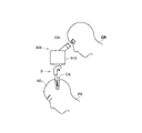
- FIG. 9 is a schematic view showing a state when a conventional surgical tool 9 (needle holder) is used in an operation such as neurosurgery.
- a conventional surgical tool 9 needle holder
- FIG. 9 a part of the head HD of the human body (patient PA) is opened, and the surgical tool 9 is inserted into the narrow and deep hole CA formed in the head HD from above.
- the optical axis OA of the objective lens 910 of the microscope 900 is aimed in the same direction as the insertion direction of the surgical tool 9, and the procedure is performed while looking into the microscope 900 and visually observing the surgical field near the tip of the surgical tool 9. There is.
- the surgical tool is inserted from above along the optical axis OA directly under the microscope 900, the doctor DR operates with the wrist floating, in other words, in a state where the hand is easily shaken.
- the tool 9 will be operated.
- the handle portion of the surgical tool 9 used in such an operation such as neurosurgery (the barrel portion corresponds to this in the needle holder described in Patent Document 1) is relatively long. The blur at hand is easily amplified by the tip of the treatment tool.
- the trigger is operated by using the middle finger to open and close the tip of the treatment tool. Since the middle finger uses the muscles (tendons) shared with the index finger and ring finger to move the finger, it is said that moving only the middle finger independently is not as good as the ring finger. If you try to move only the middle finger independently and finely, the muscles (tendons) that are widely distributed inside the hand will be moved with a delicate touch, so it will be a powerful operation as a whole and a precise operation. The palms and wrists that form the base of the fingertips are also prone to blurring. Therefore, when the treatment tool is opened and closed with the conventional surgical tool 9, the tip is easily shaken and the fine procedure is impaired.
- the procedure is often performed at a relatively shallow part from the surface of the human body, so even if the conventional surgical tool 9 is used, the longitudinal direction of the needle holder The angle can be set large with respect to the visual direction, making it relatively easy to secure a field of view near the surgical field.
- the doctor can fix the wrist near the side of the surgical field, and the operation at hand is difficult to shake.
- an object of the present invention is to provide a surgical tool capable of performing a finer procedure more accurately than in the past.
- a treatment unit consisting of a pair of treatment pieces whose tip opens and closes, a rod-shaped rod-shaped body in which the treatment unit is connected to the tip side and extends along a longitudinal direction line, and an opening to the tip side.
- a substantially cylindrical fixed cylinder having a hole and the rear end side of the rod-shaped body rotatably engaged with the longitudinal direction line on the inner wall of the hole, and the fixed cylinder as a part to be gripped by the user.
- a surgical instrument is provided with a grip provided in the.
- Such surgical tools further include a slider handle mounted on the outer peripheral surface of the rod.
- the surgical tool is configured such that the slider handle slides back and forth along the longitudinal direction line with respect to the rod-shaped body (excluding the push rod in this case) and rotates around the longitudinal direction line. .. Further, in such a surgical tool, a pair of treatment pieces of the treatment unit can be opened and closed by moving the slider handle back and forth along the longitudinal direction line, and the treatment unit can be opened and closed by rotating the slider handle around the longitudinal direction line. It is configured to rotate around a longitudinal line.
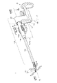
- FIG. It is a perspective view of the surgical instrument 1 which concerns on Embodiment 1.
- FIG. It is sectional drawing of the surgical instrument 1 which concerns on Embodiment 1.
- FIG. It is a main part explanatory drawing which shows for demonstrating the structure which concerns on the 1st connection part of Embodiment 1.
- FIG. It is a figure which shows for demonstrating the structure which concerns on the 2nd connecting part of Embodiment 1.
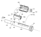
- FIG. It is a main part perspective view which shows for demonstrating the structure which concerns on the 2nd connecting part of Embodiment 1.
- FIG. It is a figure which shows for demonstrating the structure which concerns on the opening / closing conversion part of Embodiment 1.
- FIG. It is a perspective view which shows for demonstrating the use example of the surgical instrument 1 which concerns on Embodiment 1.
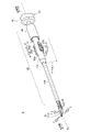
- FIG. It is a perspective view of the surgical instrument 2 which concerns on Embodiment 2.
- FIG. It is a schematic diagram which shows the state when the conventional surgical tool 9 is used in the operation such
- FIGS. 1 to 7 are used for explaining the first embodiment, they also show specific examples of the present invention. Therefore, when a specific example of the first embodiment is described, it is sometimes referred to as an "example".
- FIG. 1 is a perspective view of the surgical instrument 1 according to the first embodiment.
- FIG. 2 is a cross-sectional view of the surgical instrument 1 according to the first embodiment.
- the surface including the curved direction and the longitudinal direction line LL of the treatment pieces 11 and 12 and the surface including the grip portion 30 and the longitudinal direction line LL do not always coincide with each other, but they are the same in FIG. It is shown in the same drawing assuming that it is a surface.
- the surgical instrument 1 includes a treatment unit 10, a rod-shaped body 100, a fixed cylinder portion 20, a grip portion 30, and a slider handle 200.
- the "longitudinal direction line LL" is a line along the longitudinal direction of the rod-shaped body 100 and is a virtual line forming a central axis when the rod-shaped body 100 rotates.
- the "bottom” is a general description of the direction in which the grip portion 30 protrudes from the longitudinal direction line LL of the rod-shaped body 100, and the "top” is the direction opposite to the "bottom”.
- “Upper” and “lower” are names for convenience, and do not necessarily correspond to the vertical direction along the vertical direction when used.
- the treatment unit 10 is composed of a pair of treatment pieces 11 and 12 whose tips are opened and closed.
- the treatment unit 10 is divided into at least two pieces, and may be any unit as long as the tips open and close around the opening / closing shaft 19 (see FIG. 2).
- the treatment unit 10 is not limited to the needle holding tool, and is preferably applied as the treatment unit 10 to a pair of tweezers / forceps for grasping / grasping an object or a scissors for cutting an object. can do. That is, the treatment unit 10 may be a needle holder, tweezers, or forceps. Further, the treatment unit 10 may be a pair of scissors.
- the tip of the treatment unit 10 in the first embodiment is located at a position radially away from the longitudinal direction line LL.
- the tip end side of the treatment pieces 11 and 12 is curved so as to be separated from the longitudinal direction line LL as the opening / closing shaft 19 toward the tip of the treatment pieces 11 and 12.
- the tip of the treatment unit 10 may be bent from the middle of the treatment portions 11a and 12a ⁇ see FIG. 6A described later >> to form a substantially L-shape.
- Rod-shaped body 100 refers to a total of rod-shaped members extending between the treatment unit 10 and the fixed cylinder portion 20 (described later) and extending along the longitudinal direction line LL.
- the rod-shaped body 100 includes a hollow pipe 130 described later, a push rod 110 inserted inside the hollow pipe 130, a barrel 140 connected to the outer peripheral surface of the hollow pipe 130, and the like.
- a treatment unit 10 is connected to the tip end side of the rod-shaped body 100, and a fixed cylinder portion 20, a grip portion 30, and the like, which will be described later, are arranged on the rear end side.
- the treatment unit 10 is engaged via the flat plate 120, the upper boss 123 protruding from the flat plate 120, and the lower boss 124. Further, inside the barrel 140, a hollow member 150 that can move forward and backward along the longitudinal direction line LL and is rotatable around the longitudinal direction line LL is arranged inside the barrel 140. The hollow member 150 is rotatable so that its central axis coincides with the longitudinal direction line LL, and can move back and forth along the longitudinal direction line LL.
- the "tip side” means the side where the treatment unit 10 is arranged with respect to the rod-shaped body 100
- the "rear end side” means the side where the fixed cylinder portion 20 is arranged with respect to the rod-shaped body 100. Shall refer to the side that was done.
- the fixed cylinder portion 20 is a substantially cylindrical portion having a hole 22 opened on the tip side.
- a guide groove 24 (see FIG. 2) cut along the circumferential direction is formed on the inner wall of the hole 22.
- a flange-shaped flange portion 144 protruding in the radial direction RD from the longitudinal direction line LL is formed on the rear end side of the barrel 140 constituting the rod-shaped body 100, and the flange portion 144 is a guide for the fixed cylinder portion 20. Engages in the groove 24.
- the fixed cylinder portion 20 is rotatably engaged with the rear end side (more specifically, the rear end side of the barrel 140) of the rod-shaped body 100 on the inner wall of the hole 22 about the longitudinal direction line LL. It is a thing.
- the shape of the opening of the fixed cylinder portion 20 is substantially circular, but if the fixed cylinder portion 20 and the rod-shaped body 100 are finally rotatable, the shape is particularly limited to the substantially circular shape. It is not something that will be done.
- the grip portion 30 is a portion integrally provided with the fixed cylinder portion 20 as a portion to be gripped by the user of the surgical tool 1.
- the grip portion 30 is formed so as to project from the longitudinal direction line LL in the radial direction RD.
- the fixed cylinder portion 20 and the grip portion 30 may be integrally formed (coupled), or those formed separately may be connected to each other.
- the grip portion 30 has at least a finger hook portion 32 and a palm rest portion 34.
- the finger hook portion 32 includes a finger hook surface 32a, which is a surface for hanging a user's finger.
- the direction of the tangent line L1 of the finger resting surface 32a is set to intersect the longitudinal direction line LL.
- the tangent line of the finger hook surface 32a is not parallel to the longitudinal direction line LL.
- the tangent line of the finger hook surface 32a is orthogonal to the longitudinal direction line LL.
- the finger hook portion 32 is arranged at a position offset by a predetermined dimension in the radial direction of the rod-shaped body 100 from the longitudinal direction line LL (see FIG. 2).
- the offset amount is set according to the size of the palm of the user and the like, and is preferably set within the range of approximately 5 mm to 50 mm.
- the finger hook portion 32 is a portion on which at least the middle finger of the user is hung.
- the present invention is not limited to the middle finger, and the finger hook portion 32 may be configured as a portion on which the ring finger is hung in addition to the middle finger.
- the grip portion 30 and the fixed cylinder portion 20, which are the basis for operating the surgical instrument 1 are gripped so as to be sandwiched between the two fingers of the middle finger and the ring finger and the palm. It can be stabilized and more accurate procedure can be performed (how to use will be described later).
- the palm portion 34 is a portion that is applied to the user's palm when the user grips the surgical tool 1.
- the palm rest portion 34 is arranged on the rear end side when viewed from the finger hook portion 32.
- the shape of the palm rest portion 34 can be an appropriate shape, but in the embodiment, the shape is like a hemispherical shape of a rugby ball (a shape similar to a mouse for a PC), and is substantially parallel to the long axis thereof.
- the longer curved surface portion is arranged so as to hit the palm as the palm contact surface 34a.
- the palm rest portion 34 may be fixedly configured with respect to the finger hook portion 32, but the distance between the palm rest portion 34 and the slider handle 200 (in the direction along the longitudinal direction line LL) can be changed. It is preferable that it is.
- the stay 35 is coupled to the side opposite to the palm contact surface 34a of the palm contact portion 34, and on the other hand, the grip portion intermediate portion 36 is provided on the rear end side of the longitudinal direction line LL from the finger hook portion 32. After projecting, a stay hole 36a that opens on the rear end side of the grip portion intermediate portion 36 is provided, and the stay 35 is inserted into the stay hole 36a so as to be able to move forward and backward.
- the distance between the palm rest portion 34 and the finger resting surface 32a can be changed, and as a result, the distance between the palm rest portion 34 and the slider handle 200 can be changed. ..
- the position of the palm rest portion 34 can be fixed by fastening the set screw 37 at the stage where the distance is set.
- the distance between the palm rest portion 34 and the slider handle 200 can be changed in this way, it can be adjusted so as to be easy to grip according to the shape and size of the user's palm. It is possible to perform accurate and fine procedures.
- the shape of the palm portion 34 may be a hemispherical shape of a chicken egg, a hemispherical shape obtained by breaking a true sphere, or a substantially plate-shaped shape such as baseball. It may be shaped like a 1st to 3rd base.
- the stay 35 may be projected from the back side of the deviation portion protruding toward the rear end side, in which case. By rotating and fixing the stay 35 at an appropriate angle in the stay hole 36a, it is possible to change the portion of the palm area of the user to which the palm contact surface 34a hits. As a result, the surgical tool 1 can be gripped more accurately according to the shape and size of the palm of the user.
- Slider handle 200 The slider handle 200 is a portion operated by the user to rotate the tip of the treatment unit 10 and open / close the tip.
- the slider handle 200 is attached to the outer peripheral surface 100a of the rod-shaped body 100.
- the slider handle 200 may be mounted so as to come into contact with the outer peripheral surface 100a of the rod-shaped body 100, or may be arranged on the radial outer side of the outer peripheral surface 100a in a slightly floating state so as not to come into contact with the outer peripheral surface 100a.
- the slider handle 200 may be configured to wind the outer peripheral surface 100a of the rod-shaped body 100 by about half of its circumference (Example), or may be configured to cover only a part thereof like a commercially available slide switch.
- the surgical tool can be used so that the finger does not easily come off from the slider handle 200 even if it is rotated at a large angle.
- the slider handle 200 slides back and forth along the longitudinal direction line LL with respect to the rod-shaped body 100 ⁇ excluding the push rod 110 (described later) >> due to the structure of the first connecting portion 101, the second connecting portion 102, etc., which will be described later. Moreover, it is designed to rotate around the longitudinal direction line LL.
- the central axis of rotation of the slider handle 200 and the central axis of the rod-shaped body 100 are in a coaxial relationship. Further, the direction of the forward / backward movement of the slider handle 200 is the same as the direction of the longitudinal direction line LL.
- the slider handle 200 is operated by the user's thumb 81 and index finger 82 ⁇ See also FIG. 7 (b) described later >>. Specifically, the slider handle 200 is a portion that is sandwiched between the belly of the thumb 81 and the belly of the index finger 82 and is in contact with each other so as to be pinched and operated by both fingers, but mainly one of the thumb 81 and the index finger 82 is mainly used. This includes how to use it for operation and simply attach the other to the handle. This also includes how to operate by touching only one of the fingers depending on the user.
- the surface of the slider handle 200 is provided with wavy irregularities to prevent slipping. Further, it is preferable that the position marker 205 is provided on the surface 200a of the slider handle 200.
- the position marker 205 may be configured in any way as long as it serves as a mark of position / posture when the user touches it.
- the position marker 205 is composed of a reference protrusion that protrudes one step higher than the above-mentioned wavy unevenness (see also FIG. 3 described later).
- the present invention is not limited to this, and conversely, it may be formed of a recess or a hole or the like.
- the user can operate while recognizing the relative positional relationship of the slider handle using the position marker 205 as a clue, and the procedure can be performed more accurately. ..
- the surgical instrument 1 includes a treatment unit 10, a rod-shaped body 100, a fixed cylinder portion 20, and a gripping portion 30, and is further attached to the outer peripheral surface 100a of the rod-shaped body 100 to be attached to the rod-shaped body 100. It includes a slider handle 200 configured to slide along the longitudinal line LL and rotate around the longitudinal line LL. In the surgical tool 1, the slider handle 200 is moved back and forth along the longitudinal direction line LL to open and close the pair of treatment pieces 11 and 12 of the treatment unit 10, and the slider handle 200 is rotated around the longitudinal direction line LL. By moving, the treatment unit 10 is configured to rotate around the longitudinal direction line LL.
- the pair of treatment pieces 11 and 12 are opened in the direction of the thick arrow O in conjunction with this, and the slider handle 200 is retracted in the direction of the thick arrow B.
- the pair of treatment pieces 11 and 12 are configured to close in the direction of the thick arrow C.
- the entire treatment unit 10 is rotated in the direction of the thick arrow R in conjunction with this, and when the slider handle 200 is rotated in the direction of L, the treatment is performed in conjunction with this.
- the entire unit 10 is configured to rotate in the direction of the thick arrow L (see FIG. 1).
- the explanation will be continued focusing on the specific configuration for realizing this.
- the rod-shaped body 100 includes a push rod 110 with the treatment unit 10 engaged at the tip thereof.
- the "push rod 110" not only has a function of pushing the flat plate 120 (described later) toward the tip end side, but also has a function of pulling the flat plate 120 toward the rear end side.
- the surgical tool 1 includes a first connecting portion 101.
- the first connecting portion 101 connects the slider handle 200 and the push rod 110, and converts the back-and-forth movement of the slider handle 200 into the back-and-forth movement of the push rod 110.
- FIG. 3 is an explanatory diagram of a main part shown for explaining the structure related to the first connecting part 101 of the first embodiment.
- FIG. 3A is an exploded view of a main part when a part of the surgical instrument 1 is viewed from diagonally below. The figure shows a state in which the slider handle 200 is removed from the barrel 140, and the screw 194 for stopping the slider handle 200 is not shown.
- FIG. 3B is a diagram showing a cross section of the push rod 110 corresponding to the region surrounded by the broken line A in FIG. 3A.
- the slider handle 200 has a substantially semi-cylindrical shape in which a cylinder is cut in about half along the axial direction, and a claw 210 is provided inside the cylinder handle 200.
- the claw 210 projects from the position of the edge on the tip end side of the slider handle 200 toward the rotation axis (longitudinal direction line LL in the mounted state) when the slider handle 200 rotates.
- the tip portion 212 of the claw 210 has an arcuate shape that follows the shape around the guide groove 105 (described later), and when the slider handle 200 rotates, the tip portion 212 becomes the guide groove 105 (described later). It is designed to slide while being guided along the circumference of the.
- the position of the claw 210 in the thrust direction is not limited to the edge on the tip side, and even if it is placed at an intermediate position between the tip side and the rear end side of the slider handle 200. good.
- the push rod 110 is housed in an internal space such as a hollow pipe 130 and a barrel 140.
- the push rod 110 can be slightly confirmed through the slit 142 of the barrel 140.
- the push rod 110 is formed with a guide groove 105 on the rear end side of the push rod 110 (see also FIG. 2).
- the guide groove 105 of the push rod is a groove having a smaller diameter than other parts and is formed along the circumferential direction, and is dropped into the guide groove 105 to which the tip portion 212 of the claw 210 of the slider handle is applied. Is designed to engage.
- a slit 142 is formed in the barrel 140, and when the slider handle 200 is combined with the push rod 110 through the slit 142, the tip portion 212 of the claw 210 of the slider handle engages with the guide groove 105 of the push rod 110. connect.
- the slider handle 200 is moved back and forth along the thrust direction in such a state, the vicinity of the tip portion 212 of the claw 210 pushes the inner walls 105a and 105b of the guide groove 105 ⁇ see FIG. 3B >>, As a result, the entire push rod 110 also moves back and forth along the thrust direction.
- the first connecting portion 101 is configured by the tip portion 212 of the claw 210 of the slider handle and the guide groove 105 of the push rod 110.
- FIG. 4 is a diagram shown for explaining the structure related to the second connecting portion 102 of the first embodiment.
- FIG. 4A is a cross-sectional view for explaining the fixing portion 107 of the rod-shaped body 100 for fixing the opening / closing shaft 19.
- FIG. 4B is a cross-sectional view taken along the line BB of FIG. 4A.
- FIG. 5 is a perspective view of a main part shown for explaining the structure related to the second connecting portion 102 of the first embodiment.
- the display of the tip side from the middle portion of the rod-shaped body 100, the fixed cylinder portion 20, the grip portion 30, and the like is omitted.
- the hollow member 150 and the slider handle 200 are shown in a state of being removed from the barrel 140.
- the surgical instrument 1 includes a second connecting portion 102 (see FIG. 5 for reference numeral 102).
- the second connecting portion 102 connects the slider handle 200 and the "fixing portion 107 of the rod-shaped body 100 for fixing the opening / closing shaft 19 of the treatment unit 10", and converts the rotation of the slider handle 200 into the rotation of the treatment unit 10. It is something to do.
- the fixing portion 107 of the rod-shaped body 100 for fixing the opening / closing shaft 19 of the treatment unit 10 here may be made of any member as long as it fixes the opening / closing shaft 19. In the first embodiment, as shown in FIG.
- the “fixing portion 107 of the rod-shaped body 100 for fixing the opening / closing shaft 19” includes a treatment unit base 135 that supports the opening / closing shaft 19 from the tip side and a treatment unit at the tip. It is composed of a hollow pipe 130 to which the base 135 is connected, and a barrel 140 to which the hollow pipe 130 is fitted and connected to the hollow pipe 130 by a screw 192.
- an engaging ridge portion 230 is provided that protrudes in a long shape from the inner wall toward the central axis of rotation.
- An inner groove 230a is also provided near the center of the engaging ridge portion 230.
- an engaging groove 154 is provided on the outside of the hollow member 150.
- an inner protrusion 154a that follows the shape of the inner groove 230a described above is also provided near the center of the engagement groove 154. Therefore, when assembled as the surgical tool 1, the engaging ridge portion 230 of the slider handle 200 engages with the engaging groove 154 of the hollow member 150 through the slit 142 of the barrel 140 ⁇ FIG. 4 See also (b) >>.
- the slider handle 200 is fastened to the screw hole 156 of the hollow member 150 by a screw 194 (not shown in FIG. 5) through the slit 142 of the barrel 140.
- the slider handle 200 is connected to the rod-shaped body 100 without falling off.
- the claw 210 of the slider handle passes through the portion of the notch 152 of the hollow member 150 so as not to interfere with the hollow member 150.
- the side surface 230b of the engaging ridge portion 230 of the slider handle 200 hits the inner wall 142a of the slit 142 of the barrel 140 and pushes it.
- the entire barrel 140 will also rotate ⁇ see FIGS. 4 (b) and 5 >>.
- the barrel 140 forms a part of the "fixing portion 107 of the rod-shaped body 100 for fixing the opening / closing shaft 19", and is indirectly coupled to the opening / closing shaft 19 to be integrated. Therefore, the opening / closing shaft 19 rotates due to the rotation of the barrel 140, and the treatment unit 10 whose tip opens / closes around the opening / closing shaft 19 also rotates.
- the second connecting portion 102 is configured by the engaging ridge portion 230 (more specifically, the side surface 230b) of the slider handle and the slit 142 (more specifically, the inner wall 142a of the slit). ..
- Open / close conversion unit 103 The surgical tool 1 includes an open / close conversion unit 103.
- the open / close conversion unit 103 converts the forward / backward movement of the push rod 110 into the opening / closing of the treatment unit 10.
- FIG. 6 is a diagram shown for explaining the structure related to the open / close conversion unit 103 of the first embodiment.
- 6 (a) is an exploded view of the open / close conversion unit 103
- FIG. 6 (b) is a plan view showing a state when the treatment unit 10 is opened in the open / close conversion unit 103
- FIG. 6 (c) is a treatment. It is a top view which shows the state when a unit 10 is closed.
- the treatment unit 10 is composed of a pair of treatment pieces including the treatment piece 11 and the treatment piece 12.
- Shaft holes 11c and 12c are formed in the treatment pieces 11 and 12, respectively.
- Each of the treatment pieces 11 and 12 has treatment portions 11a and 12a on the distal end side of the shaft holes 11c and 12c, respectively, and has operation portions 11b and 12b on the rear end side of the shaft holes 11c and 12c, respectively.
- the pair of treatment pieces 11 and 12 are connected by an opening / closing shaft 19 commonly inserted into the shaft holes 11c and 12c of the treatment pieces 11 and 12, respectively.
- the opening / closing shaft 19 is composed of a pin 18 and a pin cap 18a.
- cam grooves 11d and 12d having predetermined angles ⁇ 1 and ⁇ 2 ⁇ see FIG. 6C >> with respect to the longitudinal direction line LL when the treatment unit 10 is closed are formed, respectively.
- the predetermined angles ⁇ 1 and ⁇ 2 are preferably in the range of approximately 1 to 5 °, respectively. For example, it is more preferably in the range of 2 to 3 °.
- a flat plate 120 is arranged at the tip of the push rod 110.
- the flat plate 120 is provided with an upper boss 123 on the first surface 121, and a lower boss 124 is provided on the second surface 122, which is a surface opposite to the first surface 121.
- the upper boss 123 and the lower boss 124 are arranged at the same position when viewed in a plan view. However, it is not limited to that. Then, the upper boss 123 is engaged with the cam groove 11d of one treatment piece 11, and the lower boss 124 is engaged with the cam groove 12d of the other treatment piece 12.
- the upper boss 123 and the lower boss 124 of the flat plate 120 have cam grooves 11d and 12d having predetermined angles, respectively. It is an intersection of the above and is located on the tip side of the cam grooves 11d and 12d. At this time, the operation portions 11b and 12b are open on the tip side with the opening / closing shaft 19 as the center.
- the upper boss 123 and the lower boss 124 are the intersections of the cam grooves 11d and 12d having predetermined angles, respectively, and the cam grooves It will be located on the rear end side of 11d and 12d.
- the operation portions 11b and 12b are closed on the tip side with the opening / closing shaft 19 as the center.
- the positions of the upper boss 123 and the lower boss 124 move along the cam grooves 11d and 12d, and the tips of the treatment portions 11a and 12a are opened accordingly. It is designed to shift to the closed state from.
- the opening / closing conversion unit 103 is configured by the treatment piece of the above.
- the pair of treatment pieces 11 and 12 of the treatment unit 10 can be opened and closed by moving the slider handle 200 back and forth along the longitudinal direction line LL.
- the treatment unit 10 is configured to rotate around the longitudinal line LL by rotating the slider handle 200 around the longitudinal line LL.
- the treatment unit 10 is viewed in cross section in a plane perpendicular to the longitudinal direction line LL.
- the operation portions 11b and 12b and the flat plate 120 are housed inside the outer diameter OD of the hollow pipe 130 containing the push rod 110 (shown by the width W1 in FIG. 6B).
- a hole centered on the longitudinal direction line LL is opened at the rear end of the fixed cylinder portion 20 (not shown), and the hole 22 is open at the tip end side. You may. With such a configuration, it is possible to facilitate cleaning of the inside as in the case described in Patent Document 1.
- the surgical instrument 1 according to Embodiment 1 can be suitably used in a surgical operation, for example, a brain surgery operation.
- FIG. 7 is a perspective view showing an example of use of the surgical instrument 1 according to the first embodiment.
- FIG. 7A is a diagram showing a state of the first step in which the surgical instrument 1 is started to be gripped
- FIG. 7B is a diagram showing a state of the second step in which the slider handle 200 is moved back and forth and rotated. be. Note that FIG. 7 shows an example in which the surgical instrument 1 is held in the right hand, but the relationship is the opposite when the surgical tool 1 is held in the left hand.
- the palm contact portion 34 arranged on the rear end side of the surgical tool 1 is applied to the palm 86 of the user's right hand.
- the middle finger 83 is hung on the finger hook portion 32 (finger hook surface 32a).
- the palm contact portion 34a is brought into contact with the vicinity of the center of the palm between the fingertip ball 88 and the thumb ball 87, the palm contact portion 34 is stably sandwiched between the fingertip ball 88 and the thumb ball 87.
- the surgical tool 1 can be grasped (first step).
- the user's thumb 81 and index finger 82 are brought into contact with the slider handle 200, and the slider handle 200 is grasped so as to be sandwiched between the thumb 81 and the index finger 82.
- the thumb 81 and / and the index finger 82 also touch the position marker 205 (not shown) so that the positional relationship can be grasped.
- the tip of the treatment unit 10 can be opened and closed by moving the slider handle 200 back and forth along the longitudinal direction line LL using the thumb 81 and the index finger 82, or the slider handle 200 can be rotated around the longitudinal direction line LL. By moving, the entire treatment unit 10 is rotated.
- the procedure intended by the user can be realized by the treatment unit 10 on the tip side only by the operation with the thumb 81 and the index finger 82.
- the middle finger 83 is a finger unsuitable for precise operation. If you try to perform a precise operation with the middle finger 83 to open and close the treatment unit using the conventional surgical tool 9, you will be forced, and as a result, the palm 86 and wrist 89, which are the basis of the operation, will also shake. In particular, when a long surgical tool having a large rod-shaped body is used, the blurring at hand is amplified at the tip of the treatment unit and impairs the fine procedure.
- the slider handle 200 is attached to the outer peripheral surface 100a of the rod-shaped body 100, and the slider handle 200 slides back and forth along the longitudinal direction line LL with respect to the rod-shaped body 100. , It is configured to be rotatable around the longitudinal line LL. Then, by moving the slider handle 200 back and forth along the longitudinal direction line LL, the pair of treatment pieces 11 and 12 of the treatment unit 10 are opened and closed, and by rotating the slider handle 200 around the longitudinal direction line LL. The treatment unit 10 is configured to rotate around the longitudinal direction line LL. Therefore, as shown in FIG.
- the user pinches the slider handle 200 with the thumb 81 and the index finger 82 so as to sandwich the slider handle 200, and rotates the thumb 81 and the index finger 82 to rotate the treatment unit 10.
- the treatment unit 10 can be opened and closed not only by moving the thumb 81 and the index finger 82 back and forth (advancing and retreating). That is, since the treatment unit 10 can be opened and closed without using the middle finger 83 at all, the palm 86 and the wrist 89 do not shake due to the movement of the middle finger 83 described above.
- the thumb 81 and the index finger 82 are fingers that can perform precise movements with less force than the middle finger 83 due to the way the muscles (tendons) are attached. Since the surgical tool 1 according to the first embodiment can open / close / rotate the treatment unit 10 only with the thumb 81 and the index finger 82, which can perform precise movements without force, the user can operate the slider handle 200. The operation of the treatment unit 10 can be performed accurately and finely.
- the surgical tool 1 according to the first embodiment, even if the treatment unit 10 is located at a position relatively far from the hand, the object can be accurately and precisely pinched, pinched, and rotated. You can make it. As a result, it is possible to perform a finer procedure (surgery) more accurately than in the past.
- the finger hook portion 32 is arranged at a position offset in the radial direction of the rod-shaped body 100 from the longitudinal direction line LL as the grip portion 30, and is viewed from the finger hook portion 32.
- the palm rest portion 34 is arranged on the rear end side.
- the degree of opening and closing of the treatment unit 10 is determined by the position on one axis (longitudinal direction line), it is easy to finely adjust the opening and closing, and the feeling of sandwiching the object is intuitive. It is easy to understand.
- the surgical tool 1 according to the first embodiment includes an open / close conversion unit 103 in which the boss is engaged with the cam grooves 11d and 12d as described above, and the operation units 11b and 12b and the flat plate 120 of the treatment unit 10 are provided. , It is configured to fit inside the outer diameter of the hollow pipe 130 accommodating the push rod 110 ⁇ see FIG. 6B >>. Therefore, it is easy to design the surgical tool 1 according to the first embodiment to have a smaller outer diameter of the rod-shaped body 100 than the conventional surgical tool 9.
- the rod-shaped body 100 By reducing the outer diameter of the rod-shaped body 100, for example, when trying to see the tip of the treatment unit 10 with a microscope 900 in an operation such as neurosurgery shown in FIG. 9, the rod-shaped body 100 can be prevented from obstructing the visual field. That is, the structure can be easily secured even in a narrow and deep part.
- the tip of the treatment unit 10 is located at a position radially away from the longitudinal direction line LL.
- the tip end side of the treatment pieces 11 and 12 is curved so as to move away from the longitudinal direction line LL toward the tip of the treatment pieces 11 and 12. Therefore, for example, in the case of surgery such as neurosurgery shown in FIG. 9, when the user (doctor) is viewed from a direction at a shallow angle with respect to the longitudinal direction line LL of the surgical tool 1 (rod-shaped body 100). Even so, it is easy to see the narrow and deep part located on the tip side. Therefore, the procedure can be performed more accurately.
- FIG. 8 is a perspective view of the surgical instrument 2 according to the second embodiment.
- the reference numerals in the first embodiment are used and the description thereof is omitted here.
- the surgical tool 2 according to the second embodiment basically has the same configuration as the surgical tool 1 according to the first embodiment, but is different from the surgical tool 1 according to the first embodiment in the configuration of the grip portion. That is, the grip portion 30'of the surgical tool 2 has a configuration in which the palm rest portion 34'is provided on the rear end side of the fixed cylinder portion 20', and is a finger hook portion like the grip portion 30 of the first embodiment. 32 does not have (see FIG. 8).
- the palm rest portion 34' may be directly coupled to the fixed cylinder portion 20', or may be connected to the fixed cylinder portion 20' via a stay in the same manner as the palm rest portion 34 of the first embodiment. It may have been done.
- the treatment unit 10 is rotated by rotating the slider handle 200, and the treatment is performed by moving the slider handle 200 back and forth, as in the surgical tool 1 according to the first embodiment.
- the tip of the unit 10 (a pair of treatment pieces 11 and 12) is configured to open and close.
- the surgical instrument 2 according to the second embodiment has basically the same configuration as the surgical instrument 1 according to the first embodiment except for the configuration of the grip portion. Therefore, among the effects of the surgical instrument 1 according to the first embodiment, the corresponding effect is similarly obtained.
- the treatment pieces 11 and 12 having a curved tip side have been picked up and described.
- the present invention is not limited to this.
- it may be a so-called straight-shaped treatment piece that extends along the longitudinal direction line LL over the entire treatment portions 11a and 12a of the treatment pieces 11 and 12.
- the tips of the treatment pieces 11 and 12 are located on the same axis as the axis on which the slider handle 200 is operated, it is easy to align the treatment pieces with, for example, the treatment site.
- the opening / closing conversion unit 103 is described by a method using a cam groove and a boss.
- the present invention is not limited to this.
- a push rod is brought into contact with the joint of the operation portions of the pair of treatment pieces, and then a leaf spring is applied from the outside of the operation portion.
- the opening / closing conversion unit 103 may be configured by a method of applying a restoring force with.
- a surgical tool capable of performing a complete manual operation in which the degree of opening and closing of the treatment unit 10 is maintained in that state when the forward / backward movement of the slider handle 200 is stopped, will be described as an example.
- the present invention is not limited to this, and may be a surgical tool capable of performing semi-manual / semi-automatic operation.
- a predetermined spring for example, a coil spring
- a push rod 110 is engaged is arranged inside the hollow pipe 130, and when the user releases a finger from the slider handle 200 due to the elastic force of the spring, the push rod 110 is placed.
- the tip end of the treatment unit 10 may be automatically closed.
- the push rod 110 or the like automatically retracts to the rear end side, whereby the tip of the treatment unit 10 may be automatically opened.
- 1,2,9 ... Surgical tool 10 ... Treatment unit, 11,12 ... Treatment piece, 11a, 12a ... Treatment part, 11b, 12b ... Operation part, 11c, 12c ... Shaft hole, 11d, 12d ... Cam groove, 18 ... Pin, 18a ... Pin cap, 19 ... Open / close shaft, 20, 20'... Fixed cylinder, 22 ... (Fixed cylinder) hole, 24 ... (Fixed cylinder) guide groove, 30, 30'... Grip , 32 ... fingernail part, 32a ... fingernail surface, 34,34'... palm contact part, 34a ... palm contact surface, 35 ... stay, 36 ... grip middle part, 36a ... stay hole, 37 ...
Landscapes
- Health & Medical Sciences (AREA)
- Surgery (AREA)
- Life Sciences & Earth Sciences (AREA)
- Biomedical Technology (AREA)
- Nuclear Medicine, Radiotherapy & Molecular Imaging (AREA)
- Engineering & Computer Science (AREA)
- Heart & Thoracic Surgery (AREA)
- Medical Informatics (AREA)
- Molecular Biology (AREA)
- Animal Behavior & Ethology (AREA)
- General Health & Medical Sciences (AREA)
- Public Health (AREA)
- Veterinary Medicine (AREA)
- Ophthalmology & Optometry (AREA)
- Surgical Instruments (AREA)
Priority Applications (4)
| Application Number | Priority Date | Filing Date | Title |
|---|---|---|---|
| JP2022563313A JP7420417B2 (ja) | 2020-11-18 | 2020-11-18 | 手術具 |
| CN202080101520.5A CN115916067B (zh) | 2020-11-18 | 2020-11-18 | 手术器械 |
| PCT/JP2020/043030 WO2022107251A1 (ja) | 2020-11-18 | 2020-11-18 | 手術具 |
| EP20962415.4A EP4248883B1 (en) | 2020-11-18 | 2020-11-18 | Surgical instrument |
Applications Claiming Priority (1)
| Application Number | Priority Date | Filing Date | Title |
|---|---|---|---|
| PCT/JP2020/043030 WO2022107251A1 (ja) | 2020-11-18 | 2020-11-18 | 手術具 |
Publications (1)
| Publication Number | Publication Date |
|---|---|
| WO2022107251A1 true WO2022107251A1 (ja) | 2022-05-27 |
Family
ID=81708579
Family Applications (1)
| Application Number | Title | Priority Date | Filing Date |
|---|---|---|---|
| PCT/JP2020/043030 Ceased WO2022107251A1 (ja) | 2020-11-18 | 2020-11-18 | 手術具 |
Country Status (4)
| Country | Link |
|---|---|
| EP (1) | EP4248883B1 (https=) |
| JP (1) | JP7420417B2 (https=) |
| CN (1) | CN115916067B (https=) |
| WO (1) | WO2022107251A1 (https=) |
Cited By (1)
| Publication number | Priority date | Publication date | Assignee | Title |
|---|---|---|---|---|
| JPWO2025173162A1 (https=) * | 2024-02-15 | 2025-08-21 |
Citations (5)
| Publication number | Priority date | Publication date | Assignee | Title |
|---|---|---|---|---|
| JPH07275253A (ja) * | 1994-04-05 | 1995-10-24 | Terumo Corp | 外科用器具 |
| JP2010503457A (ja) * | 2006-09-13 | 2010-02-04 | ケンブリッジ・エンドスコピック・ディヴァイセス,インコーポレーテッド | 外科用機器 |
| JP2012045031A (ja) * | 2010-08-24 | 2012-03-08 | Hoya Corp | 内視鏡用鉗子 |
| JP2013188323A (ja) * | 2012-03-13 | 2013-09-26 | Nagoya Univ | 鉗子 |
| JP2019025105A (ja) * | 2017-08-01 | 2019-02-21 | 国立大学法人信州大学 | ガングリップ型挟持器 |
Family Cites Families (9)
| Publication number | Priority date | Publication date | Assignee | Title |
|---|---|---|---|---|
| JP4270595B2 (ja) * | 1997-10-09 | 2009-06-03 | オリンパス株式会社 | 内視鏡用処置具 |
| US8029531B2 (en) * | 2006-07-11 | 2011-10-04 | Cambridge Endoscopic Devices, Inc. | Surgical instrument |
| EP2532315B1 (en) * | 2011-06-10 | 2015-08-05 | University of Dundee | Medical instrument |
| DE102011085512A1 (de) * | 2011-10-31 | 2013-05-02 | Richard Wolf Gmbh | Handhabe für ein medizinisches Instrument |
| JP6163887B2 (ja) * | 2013-06-03 | 2017-07-19 | 住友ベークライト株式会社 | 高周波処置具 |
| DE102014102097A1 (de) * | 2014-02-19 | 2015-08-20 | Karl Storz Gmbh & Co. Kg | Medizinisches Instrument |
| CN109381232B (zh) * | 2017-08-02 | 2024-02-13 | 上海市嘉定区安亭医院 | 一种用于消化内镜下微创手术的持针钳 |
| DE102017010535A1 (de) * | 2017-11-14 | 2019-05-16 | Uromed Kurt Drews Kg | Medizinisches Gerät zum Bewegen eines medizinischen Instruments |
| US11684501B2 (en) * | 2019-01-14 | 2023-06-27 | Cook Medical Technologies Llc | Multipurpose handle |
-
2020
- 2020-11-18 JP JP2022563313A patent/JP7420417B2/ja active Active
- 2020-11-18 EP EP20962415.4A patent/EP4248883B1/en active Active
- 2020-11-18 CN CN202080101520.5A patent/CN115916067B/zh active Active
- 2020-11-18 WO PCT/JP2020/043030 patent/WO2022107251A1/ja not_active Ceased
Patent Citations (5)
| Publication number | Priority date | Publication date | Assignee | Title |
|---|---|---|---|---|
| JPH07275253A (ja) * | 1994-04-05 | 1995-10-24 | Terumo Corp | 外科用器具 |
| JP2010503457A (ja) * | 2006-09-13 | 2010-02-04 | ケンブリッジ・エンドスコピック・ディヴァイセス,インコーポレーテッド | 外科用機器 |
| JP2012045031A (ja) * | 2010-08-24 | 2012-03-08 | Hoya Corp | 内視鏡用鉗子 |
| JP2013188323A (ja) * | 2012-03-13 | 2013-09-26 | Nagoya Univ | 鉗子 |
| JP2019025105A (ja) * | 2017-08-01 | 2019-02-21 | 国立大学法人信州大学 | ガングリップ型挟持器 |
Non-Patent Citations (1)
| Title |
|---|
| See also references of EP4248883A4 * |
Cited By (3)
| Publication number | Priority date | Publication date | Assignee | Title |
|---|---|---|---|---|
| JPWO2025173162A1 (https=) * | 2024-02-15 | 2025-08-21 | ||
| WO2025173162A1 (ja) * | 2024-02-15 | 2025-08-21 | 株式会社ダイヤ精機製作所 | 手術用器具 |
| JP7810468B2 (ja) | 2024-02-15 | 2026-02-03 | 株式会社ダイヤ精機製作所 | 手術用器具 |
Also Published As
| Publication number | Publication date |
|---|---|
| EP4248883A4 (en) | 2024-07-24 |
| JPWO2022107251A1 (https=) | 2022-05-27 |
| JP7420417B2 (ja) | 2024-01-23 |
| CN115916067B (zh) | 2025-03-14 |
| EP4248883A1 (en) | 2023-09-27 |
| CN115916067A (zh) | 2023-04-04 |
| EP4248883B1 (en) | 2025-11-26 |
Similar Documents
| Publication | Publication Date | Title |
|---|---|---|
| US6500188B2 (en) | Ultrasonic surgical instrument with finger actuator | |
| US8585734B2 (en) | Ergonomic handle and articulating laparoscopic tool | |
| US5358508A (en) | Laparoscopic device | |
| US5591203A (en) | Anastomosis cuff manipulator tool | |
| KR101149490B1 (ko) | 외과용 기구 | |
| EP2147638A1 (en) | Endoscopically inserting surgical tool | |
| JPH10127651A (ja) | 手術用処置具 | |
| CN103690222A (zh) | 腹腔镜手术钳 | |
| WO2008120190A2 (en) | Surgical instrument usable as a grasper and/or probe | |
| US9717485B1 (en) | Ergonomic multi-functional handle for use with a medical instrument | |
| US6077278A (en) | Suture needle holder | |
| WO2022107251A1 (ja) | 手術具 | |
| US11497486B2 (en) | Endoscopic needle carrier | |
| JP7780453B2 (ja) | 内視鏡処置具、及び内視鏡装置 | |
| US10058311B1 (en) | Ergonomic multi-functional handle for use with a medical instrument | |
| JP6933336B2 (ja) | ガングリップ型挟持器 | |
| JP2020527392A (ja) | 縫合糸配置装置および方法 | |
| JP2009195451A (ja) | 操作機構及び該操作機構を備える医療用器具 | |
| US20120253364A1 (en) | Surgical Instrument Handle and Grip | |
| JP2003135474A (ja) | 医療装置と手術用処置具 | |
| KR101481881B1 (ko) | 기능성 수술용 지침기 | |
| US6626892B1 (en) | Medical instrument | |
| CN204863380U (zh) | 新型两用微创手术钳 | |
| JP7822956B2 (ja) | 内視鏡処置具、及び内視鏡装置 | |
| CN108451555A (zh) | 一种外科手持器械及其使用方法 |
Legal Events
| Date | Code | Title | Description |
|---|---|---|---|
| 121 | Ep: the epo has been informed by wipo that ep was designated in this application |
Ref document number: 20962415 Country of ref document: EP Kind code of ref document: A1 |
|
| ENP | Entry into the national phase |
Ref document number: 2022563313 Country of ref document: JP Kind code of ref document: A |
|
| NENP | Non-entry into the national phase |
Ref country code: DE |
|
| ENP | Entry into the national phase |
Ref document number: 2020962415 Country of ref document: EP Effective date: 20230619 |
|
| WWG | Wipo information: grant in national office |
Ref document number: 202080101520.5 Country of ref document: CN |
|
| WWG | Wipo information: grant in national office |
Ref document number: 2020962415 Country of ref document: EP |