WO2022102485A1 - 射出成形機の型締装置 - Google Patents
射出成形機の型締装置 Download PDFInfo
- Publication number
- WO2022102485A1 WO2022102485A1 PCT/JP2021/040481 JP2021040481W WO2022102485A1 WO 2022102485 A1 WO2022102485 A1 WO 2022102485A1 JP 2021040481 W JP2021040481 W JP 2021040481W WO 2022102485 A1 WO2022102485 A1 WO 2022102485A1
- Authority
- WO
- WIPO (PCT)
- Prior art keywords
- mold
- platen
- fixed
- movable
- parallelism
- Prior art date
- Legal status (The legal status is an assumption and is not a legal conclusion. Google has not performed a legal analysis and makes no representation as to the accuracy of the status listed.)
- Ceased
Links
Images


Classifications
-
- B—PERFORMING OPERATIONS; TRANSPORTING
- B29—WORKING OF PLASTICS; WORKING OF SUBSTANCES IN A PLASTIC STATE IN GENERAL
- B29C—SHAPING OR JOINING OF PLASTICS; SHAPING OF MATERIAL IN A PLASTIC STATE, NOT OTHERWISE PROVIDED FOR; AFTER-TREATMENT OF THE SHAPED PRODUCTS, e.g. REPAIRING
- B29C45/00—Injection moulding, i.e. forcing the required volume of moulding material through a nozzle into a closed mould; Apparatus therefor
- B29C45/17—Component parts, details or accessories; Auxiliary operations
- B29C45/64—Mould opening, closing or clamping devices
- B29C45/66—Mould opening, closing or clamping devices mechanical
- B29C45/661—Mould opening, closing or clamping devices mechanical using a toggle mechanism for mould clamping
Definitions
- the present invention relates to a mold clamping device for an injection molding machine.
- the injection molding machine injects a resin material into the cavity of the mold (fixed mold and movable mold) to perform molding.
- injection compression molding is performed when molding a thin-walled member or a member that requires high dimensional accuracy (see JP-A-2000-229343).
- a resin material is injected into an open mold, and then the mold is closed to compress the resin in the cavity.
- the mold In injection compression molding, the mold is not closed at the time of injection, so the parallelism between the fixed mold and the movable mold is a problem. If the injection is performed in a state where the fixed mold and the movable mold are not kept parallel to each other and then the mold is closed, the thickness of the molded product tends to be uneven. As a result, the molded product may be defective.
- the purpose is to provide a mold clamping device for an injection molding machine that can maintain parallelism between a fixed mold and a movable mold with a simple configuration.
- the mold clamping device of the injection molding machine injects resin into a cavity formed in a state where the fixed mold and the movable mold are open, and after the injection of the resin, the movable mold is closed in the closing direction.
- It is a mold clamping device of an injection molding machine that moves and compresses the cavity to mold a molded product, and is a fixed platen that holds the fixed mold, a rear platen, and a plurality of connecting the fixed platen and the rear platen.
- the movable mold is arranged between the tie bar, the fixed platen and the rear platen, and the movable mold is held so that the fixed mold and the movable mold face each other, and the movable mold can be moved along the axial direction of the tie bar.
- the movable platen is provided between the fixed platen and the movable platen, and at least three parallelities are maintained to maintain the parallelism between the fixed mold and the movable mold when the resin is injected into the cavity. It is equipped with a mechanism.
- Each of the at least three parallelism holding mechanisms has a spring member and is said to generate an urging force that separates the fixed mold from the movable mold at least when the resin is injected into the cavity.
- a shrinking member that can be reduced in the axial direction, and a length adjusting member that can adjust the length in the axial direction in order to adjust the urging force generated in the shrinking member at least when the resin is injected into the cavity. including.
- the parallelism between the fixed mold and the movable mold can be maintained by using a simple configuration.
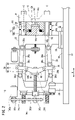
- FIG. 1 is a diagram showing a mold clamping device of an injection molding machine according to an embodiment, and represents a mold clamping device in a state where the mold is completely opened.
- FIG. 2 is a diagram showing a mold clamping device of an injection molding machine according to an embodiment, and shows a mold clamping device when a resin is injected into a mold 14 in a slightly opened state.
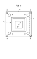
- FIG. 3 is a diagram showing the positional relationship between the tie bar shown in FIG. 1 and the four parallelism holding mechanisms.
- FIG. 4 is a diagram showing a specific configuration of the parallelism holding mechanism shown in FIG.
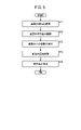
- FIG. 5 is a flowchart showing a procedure of injection compression molding using the mold clamping device of the injection molding machine according to the embodiment.
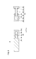
- FIG. 6 is a diagram showing the parallelism holding mechanism according to the modified example 2.
- FIG. 1 and 2 are views showing the mold clamping device 10 of the injection molding machine according to the present embodiment.
- the mold clamping device 10 is provided on the base 12.
- the mold clamping device 10 is a device for opening and closing the mold 14.
- the injection molding machine has an injection device (not shown).
- the injection device is provided on the base 12 and injects the molten resin into the mold 14.
- the injection molding machine injects the resin into the cavity CA formed in the mold 14 in a slightly open state (see FIG. 2).
- FIG. 2 shows a mold clamping device 10 when the resin is injected into the mold 14 in a slightly opened state.
- the base 12 is a base for installing the mold clamping device 10 and the injection device.
- the mold clamping device 10 has a fixed platen 18, a rear platen 20, a movable platen 22, a toggle mechanism 24, and a mold opening / closing mechanism 26.
- the fixed platen 18 and the rear platen 20 are arranged on the base 12.
- the fixed platen 18 and the rear platen 20 are connected to each other by four tie bars 28 through which the movable platen 22 is inserted.
- the four tie bars 28 extend in the axial direction A in parallel with each other.
- the axis direction A is parallel to the axis C of the tie bar 28.
- the movable platen 22 is installed between the fixed platen 18 and the rear platen 20 on the base 12 via the slide portion 32.
- the slide portion 32 can move along the guide rail 34 provided on the base 12 in the axial direction A.
- the movable platen 22 can move forward and backward in the axial direction A with respect to the fixed platen 18 and the rear platen 20.
- the mold 14 has a fixed mold 14a and a movable mold 14b facing each other.
- the fixed mold 14a is attached to the surface of the fixed platen 18 facing the movable platen 22.
- the movable mold 14b is attached to the surface of the movable platen 22 facing the fixed platen 18.
- the fixed mold 14a and the movable mold 14b each have a concave portion 14c and a convex portion 14d that can slide with each other in the axial direction A.
- the movable mold 14b is brought close to the fixed mold 14a, and the convex portion 14d of the movable mold 14b is inserted into the concave portion 14c of the fixed mold 14a.
- a cavity CA is formed between the concave portion 14c and the convex portion 14d (see FIG. 2).
- the mold 14 is somewhat open. Therefore, the volume of the cavity CA in the mold 14 of FIG. 2 is larger than the volume of the cavity CA in the mold 14 in the completely closed state.
- a flow path 14f is formed in the fixed mold 14a.
- the flow path 14f is a flow path for injecting resin from the outside of the mold 14 into the cavity CA along the axial direction A.
- the flow path 14f suppresses the non-uniformity of the parallelism of the mold 14 due to the injection of the resin.
- an opening of the flow path 14f is installed at the bottom of the fixed mold 14a, particularly at the center of the cavity CA seen from the axial direction A. As a result, the resin flows from the center of the cavity CA to the periphery, and the parallelism of the mold 14 can be maintained to some extent.
- a mold spring member 14m is provided between the fixed mold 14a and the movable mold 14b.
- the mold spring member 14m urges the movable mold 14b so that the movable mold 14b moves in the direction toward the fixed mold 14a.
- the mold spring member 14m limits the excessive expansion of the cavity CA due to the pressure of the resin injected into the cavity CA.
- a mold 14 and four parallelism holding mechanisms 30 are provided between the fixed platen 18 and the movable platen 22.
- the four parallelism holding mechanisms 30 are attached to the surface of the fixed platen 18 facing the movable platen 22 by bolts or the like.
- the four parallelism holding mechanisms 30 are mechanisms for maintaining parallelism between the fixed mold 14a and the movable mold 14b when the resin is injected into the mold 14.
- the four parallelism holding mechanisms 30 have at least the fixed mold 14a and the movable mold 14a and the movable mold 14a at the time of injection into the cavity CA in a state where the fixed mold 14a and the movable mold 14b are slightly opened (the state shown in FIG. 2). Maintain parallelism with 14b. The details of the parallelism holding mechanism 30 will be described later.
- the toggle mechanism 24 is provided between the rear platen 20 and the movable platen 22.
- the toggle mechanism 24 is driven by the mold opening / closing mechanism 26.
- the toggle mechanism 24 opens and closes the mold 14 in the axial direction A (opening / closing direction) by advancing / retracting the movable platen 22 with respect to the fixed platen 18.
- the toggle mechanism 24 amplifies the driving force of the mold opening / closing mechanism 26 and transmits the amplified driving force to the movable platen 22.
- the toggle mechanism 24 has a toggle link 36, a cross link 38, and a cross head 40.
- Two toggle links 36 and two cross links 38 are provided above. Further, two toggle links 36 and two cross links 38 are provided below. That is, a total of four toggle links 36 and a total of four cross links 38 are provided.
- two toggle links 36 and two cross links 38 are shown above and below the front side of the paper. The two toggle links 36 and the two cross links 38 on the back side of the paper are hidden behind.
- Each of the toggle links 36 has a first link rod 36a, a second link rod 36b, a first toggle pin 36c, a second toggle pin 36d, and a third toggle pin 36e.
- first link rod 36a is rotatably connected to the movable platen 22 via the first toggle pin 36c.
- One end of the second link rod 36b is rotatably connected to the rear platen 20 via the second toggle pin 36d.
- the other end of the first link rod 36a and the other end of the second link rod 36b are rotatably connected to each other via the third toggle pin 36e.
- the second link rod 36b is connected to the crosshead 40 via the crosslink 38.
- the crosshead 40 has an arm 42 that extends upwards and downwards.
- a cross link 38 is connected to the tip of the arm 42.
- the mold opening / closing mechanism 26 drives the toggle mechanism 24 to open / close the mold 14 in the axial direction A (opening / closing direction).
- the mold opening / closing mechanism 26 includes a mold opening / closing motor 26a (drive source), a drive pulley 26b, a belt 26c, a driven pulley 26d, a ball screw 26e, and a ball screw nut 26f.
- the ball screw 26e is provided along the axial direction A so as to be parallel to the tie bar 28.
- the drive pulley 26b can rotate integrally with the rotation shaft of the mold opening / closing motor 26a.
- the driven pulley 26d can rotate integrally with the ball screw 26e.
- the belt 26c is hung on the drive pulley 26b and the driven pulley 26d.
- the belt 26c transmits the rotational force of the drive pulley 26b to the driven pulley 26d.
- the ball screw 26e is provided on the rear platen 20 so that it cannot move in the axial direction and can rotate about the axis.
- the driven pulley 26d can rotate integrally with one end of the ball screw 26e.
- the ball screw nut 26f is fixed to the crosshead 40 and is screwed with the ball screw 26e.
- the ball screw nut 26f and the crosshead 40 move along the ball screw 26e as the ball screw 26e rotates.
- the rotational force of the mold opening / closing motor 26a is transmitted to the ball screw 26e via the drive pulley 26b, the belt 26c, and the driven pulley 26d.
- the ball screw 26e rotates.
- the ball screw nut 26f and the crosshead 40 move in the axial direction A along the ball screw 26e.
- the driving force in the axial direction A of the crosshead 40 is transmitted to the movable platen 22 via the crosslink 38 and the toggle link 36.
- the movable platen 22 moves along the axial direction A.
- FIG. 2 shows the mold 14 in a slightly open state before the mold 14 is completely closed.
- FIG. 3 is a diagram showing the positional relationship between the tie bar 28 shown in FIG. 1 and the four parallelism holding mechanisms 30.
- the four tie bars 28 form a substantially rectangular parallelepiped space S surrounding the mold 14 (fixed mold 14a and movable mold 14b).
- the four parallelism holding mechanisms 30 are arranged outside the space S. More specifically, the four parallelism holding mechanisms 30 are arranged along the outer circumference of each of the four tie bars 28. This prevents the parallelism holding mechanism 30 from obstructing the attachment of the mold 14 to the fixed platen 18 and the movable platen 22.
- FIG. 4 is a diagram showing a specific configuration of the parallelism holding mechanism 30 shown in FIG.
- the parallelism holding mechanism 30 includes a reduction member 30a and a length adjusting member 30b.
- the parallelism holding mechanism 30 is attached to the fixed platen 18 by bolts or the like.
- the reduction member 30a has a spring member 30c and can be reduced in the axial direction A.
- the reduction member 30a includes a shaft portion 30d, a fixing member 30e, a slide member 30f, and a spring member 30c.
- the shaft portion 30d extends along the axial direction A.
- the fixing member 30e is fixed to the shaft portion 30d.
- the slide member 30f is slidable with respect to the shaft portion 30d.
- the spring member 30c is arranged between the fixing member 30e and the slide member 30f.
- the fixing member 30e is fixed to one end of the shaft portion 30d. At the other end of the shaft portion 30d, a locking portion 30g having a diameter larger than that of the shaft portion 30d is provided.
- the slide member 30f includes a plate-shaped member 30h and a tubular member 30i.
- the plate-shaped member 30h has a through hole through which the shaft portion 30d passes.
- the tubular member 30i is fixed to the plate-shaped member 30h and accommodates the locking portion 30g.
- the locking portion 30g is movably arranged inside the tubular member 30i. The locking portion 30g can be moved to the left in FIG. 4 with respect to the plate-shaped member 30h from the state where the locking portion 30g is in contact with the plate-shaped member 30h.
- the reduction member 30a is reduced in the axial direction A as the locking portion 30g moves to the left.
- the length of the length adjusting member 30b in the axial direction A can be adjusted.
- the length adjusting member 30b has a first member 30k and a second member 30m.
- the first member 30k extends along the axial direction A.
- the second member 30m extends along the axial direction A and is screwed with the first member 30k.
- the first member 30k has a male screw portion 30n, and the second member 30m has a female screw portion 30o (screw hole) to be screwed with the male screw portion 30n.
- the first member 30k may have a female threaded portion 30o, and the second member 30m may have a male threaded portion 30n.
- the length of the length adjusting member 30b in the axial direction A can be adjusted by the relative rotation between the first member 30k and the second member 30m.
- the parallelism holding mechanism 30 is a rod-shaped member having a reduction member 30a and a length adjusting member 30b. That is, the reduction member 30a and the length adjusting member 30b are connected to each other along the axial direction A to form a rod-shaped member. Specifically, the slide member 30f of the reduction member 30a and the second member 30m of the length adjusting member 30b are connected to each other.
- the partition wall 30p is arranged at the boundary between the slide member 30f and the second member 30m. However, this partition wall 30p may be omitted.
- the resin is injected into the cavity CA formed in the mold 14 in a slightly open state (see FIG. 2).
- the position of the movable mold 14b shown in FIG. 2 is defined as the injection position.
- the length of each of the four parallelism holding mechanisms 30 in the axial direction A is longer than the distance between the fixed mold 14a and the movable mold 14b at the injection position. Therefore, when the movable mold 14b comes to the injection position, the reduction member 30a (spring member 30c) of each of the four parallelism holding mechanisms 30 is reduced. As a result, a force (urging force) for opening the mold 14 is generated in the shrinking member 30a. That is, at least when the resin is injected into the cavity CA, the shrinking member 30a shrinks, so that an urging force that separates the fixed mold 14a and the movable mold 14b from each other is generated.
- the length of the length adjusting member 30b in the axial direction A can be adjusted. That is, by changing the length of each of the four parallelism holding mechanisms 30, the urging force generated in each of the four parallelism holding mechanisms 30 can be adjusted. Therefore, by adjusting the length of each length adjusting member 30b of the parallelism holding mechanism 30, the parallelism of the mold 14 (fixed mold 14a and movable mold 14b) can be maintained at least at the time of injection. ..
- the plurality of parallelism holding mechanisms 30 may be adjusted corresponding to each of the plurality of molds 14, and then the parallelism holding mechanism 30 may be replaced according to the mold 14. This makes it possible to omit the measurement of parallelism and the adjustment of the parallelism maintaining mechanism 30 immediately before injection.
- FIG. 5 is a flowchart showing a procedure of injection compression molding using the mold clamping device 10 of the injection molding machine according to the present embodiment.
- the procedure of injection compression molding will be described with reference to FIG.
- step ST1 Adjust the distance between the mold 14 (fixed mold 14a and movable mold 14b) (step ST2). That is, the movable mold 14b is brought close to the fixed mold 14a and moved to the injection position (see FIG. 2). Then, before the resin is injected, the parallelism of the mold 14 (fixed mold 14a and movable mold 14b) is adjusted by using the parallelism holding mechanism 30 (step ST2). That is, the parallelism of the mold 14 when the movable mold 14b is in the injection position is measured. That is, the distribution of the distance between the fixed mold 14a and the movable mold 14b is measured. Based on this measurement result, the lengths of the four length adjusting members 30b are adjusted to make the parallelism of the mold 14 uniform.
- the length of the length adjusting member 30b is increased in a place where the distance between the fixed mold 14a and the movable mold 14b is narrow.
- the urging force generated in the reduction member 30a becomes large.
- the distance (that is, parallelism) between the fixed mold 14a and the movable mold 14b can be made uniform. That is, the parallelism between the fixed mold 14a and the movable mold 14b can be maintained without changing the setting of the mold clamping device 10 itself (for example, the state of the mold opening / closing mechanism 26).
- the resin is injected into the cavity CA of the mold 14 (step ST3). That is, the resin is injected into the cavity CA while the parallelism of the mold 14 is ensured.
- the plurality of parallelism holding mechanisms 30 may be adjusted corresponding to each of the plurality of molds 14, and then the parallelism holding mechanism 30 may be replaced according to the molds 14. That is, the mold 14 and the parallelism holding mechanism 30 adjusted corresponding to the mold 14 can be once removed from the mold clamping device 10 and then reattached to perform injection.
- the resin is compression molded (step ST4). That is, after the resin is injected, the movable mold 14b is moved in the closing direction to compress the cavity CA. As a result, a molded product is formed. In this case, the mold 14 is completely closed as the cavity CA is compressed. In this way, the resin is ejected while the parallelism of the mold 14 is maintained, and then the cavity CA is compressed. Therefore, the uniformity of the thickness of the resin in the cavity CA (eventually, the uniformity of the molded product) is ensured.
- the movable mold 14b is moved in the opening direction to separate the movable mold 14b from the fixed mold 14a, and then the molded product is taken out (step ST5).
- Modification 1 Modification 1 will be described.
- the parallelism holding mechanism 30 is provided on the movable platen 22 instead of the fixed platen 18.
- the parallelism holding mechanism 30 is attached to the movable platen 22 by bolts or the like.
- the parallelism holding mechanism 30 of the present embodiment is a rod-shaped member in which the reduction member 30a and the length adjusting member 30b are connected along the axial direction A.
- the reducing member 30a and the length adjusting member 30b of the parallelism holding mechanism 30 can be made into separate members that are not connected to each other.
- FIG. 6 is a diagram showing the parallelism holding mechanism 30 according to the modified example 2.
- the cylindrical member 30i of the reduction member 30a and the second member 30m of the length adjusting member 30b are separate members separated from each other.
- the end of the tubular member 30i and the end of the second member 30m face each other and have a lid portion 30p1 and a lid portion 30p2, respectively.
- the lid portion 30p1 and the lid portion 30p2 may be omitted.
- the reduction member 30a is attached to one of the fixed platen 18 and the movable platen 22.
- the length adjusting member 30b is attached to the other of the fixed platen 18 and the movable platen 22.
- bolts are used for this attachment.
- the reduction member 30a and the length adjusting member 30b are arranged on the same axis along the axis direction A.
- the parallelism holding mechanism 30 may be three or five or more.
- the present invention is not limited to the above-described embodiment, and various configurations can be adopted without departing from the gist of the present invention.
- the mold clamping device (10) of the injection molding machine injects resin into a cavity (CA) formed in a state where the fixed mold (14a) and the movable mold (14b) are open, and the resin is said.
- a fixed platen (18) that is a mold clamping device of an injection molding machine that moves the movable mold in the closing direction to compress the cavity and molds a molded product after injection, and holds the fixed mold.
- the rear platen (20), a plurality of tie bars (28) connecting the fixed platen and the rear platen, and the fixed platen and the rear platen are arranged so that the fixed mold and the movable mold face each other.
- the length in the axial direction can be adjusted in order to adjust the shrinking member (30a) that can be reduced in the axial direction and the urging force generated in the shrinking member at least when the resin is injected into the cavity.
- Each of at least three of the parallelism holding mechanisms is a rod-shaped member (parallelism holding mechanism 30) in which the reduction member and the length adjusting member are connected along the axial direction, and the fixed platen.
- each of the at least three parallelism-maintaining mechanisms provided on the movable platen with the fixed mold so that an urging force is generated on the shrinking member at least when the resin is injected into the cavity. Pressed by the movable mold.
- the parallelism between the fixed mold and the movable mold can be maintained at the time of injection by using the fixed platen or at least three of the parallelism holding mechanisms provided on the movable platen.
- the reduction member is provided on one of the fixed platen and the movable platen, and the length adjusting member is provided on the fixed platen or the other of the movable platen to maintain at least three parallelisms.
- the length adjusting member presses the shrinking member so that an urging force is generated on the shrinking member at least when the resin is injected into the cavity.
- the length adjusting member has a first member (30k) extending along the axial direction and a second member (30m) extending along the axial direction and screwing with the first member. ..
- the length of the length adjusting member in the axial direction can be adjusted by relatively rotating the first member and the second member.
- the reduction member includes a shaft portion (30d) extending along the axis direction, a fixing member (30e) fixed to the shaft portion, and a slide member (30f) slidable with respect to the shaft portion. And the spring member arranged between the fixing member and the slide member. As a result, at the time of injection, the spring member shrinks in the axial direction to generate an urging force that separates the fixed mold from the movable mold.
Landscapes
- Engineering & Computer Science (AREA)
- Manufacturing & Machinery (AREA)
- Mechanical Engineering (AREA)
- Moulds For Moulding Plastics Or The Like (AREA)
- Injection Moulding Of Plastics Or The Like (AREA)
Abstract
Description
射出成形機の型締装置10を用いて、次のように、金型14の平行度を保持した状態で、射出圧縮成形を行うことができる。図5は、本実施形態に係る射出成形機の型締装置10を用いた射出圧縮成形の手順を表すフローチャートである。以下、図5に基づき、射出圧縮成形の手順を説明する。
変形例1について説明する。変形例1では、平行度保持機構30は、固定プラテン18ではなく、可動プラテン22に設ける。この場合、平行度保持機構30は、ボルト等によって、可動プラテン22に取り付けられる。
既述のように、本実施形態の平行度保持機構30は、縮小部材30aと長さ調節部材30bとが軸線方向Aに沿って接続された、棒状部材である。これに対して、平行度保持機構30の縮小部材30aと長さ調節部材30bとを、互いに接続されない、別部材とすることも可能である。
本実施形態および変形例1、2において、平行度保持機構30は、3つでもよく、5つ以上としてもよい。なお、本発明は、上述した実施形態に限らず、本発明の要旨を逸脱することなく、種々の構成を取り得る。
上記実施形態および変形例から把握しうる発明について、以下に記載する。
Claims (5)
- 固定金型(14a)と可動金型(14b)とが開いた状態で形成されるキャビティ(CA)内に樹脂を射出し、前記樹脂の射出後に前記可動金型を閉方向に移動させて前記キャビティを圧縮して成形品を成形する射出成形機の型締装置(10)であって、
前記固定金型を保持する固定プラテン(18)と、
リアプラテン(20)と、
前記固定プラテンと前記リアプラテンを連結する複数のタイバー(28)と、
前記固定プラテンと前記リアプラテンとの間に配置され、前記固定金型と前記可動金型とが互いに向き合うように前記可動金型を保持し、前記タイバーの軸線方向(C)に沿って移動可能な可動プラテン(22)と、
前記固定プラテンと前記可動プラテンとの間に設けられ、少なくとも樹脂の前記キャビティ内への射出時に前記固定金型と前記可動金型の平行度を保つための少なくとも3つの平行度保持機構(30)と、を備え、
少なくとも3つの前記平行度保持機構の各々は、
ばね部材(30c)を有し、少なくとも樹脂の前記キャビティ内への射出時に、前記固定金型と前記可動金型とを離間させる付勢力を発生させるために前記軸線方向に縮小可能な縮小部材(30a)と、
少なくとも樹脂の前記キャビティ内への射出時に、前記縮小部材に発生する付勢力を調整するために前記軸線方向の長さが調節可能な長さ調節部材(30b)と、
を含む、射出成形機の型締装置。 - 請求項1に記載の射出成形機の型締装置であって、
少なくとも3つの前記平行度保持機構の各々は、前記縮小部材と前記長さ調節部材とが前記軸線方向に沿って接続された棒状部材であり、前記固定プラテン、又は、前記可動プラテンに設けられ、
少なくとも3つの前記平行度保持機構の各々は、少なくとも樹脂の前記キャビティ内への射出時には、前記縮小部材に付勢力が発生するように、前記固定金型と前記可動金型とによって押圧される、射出成形機の型締装置。 - 請求項1に記載の射出成形機の型締装置であって、
前記縮小部材は、前記固定プラテンおよび前記可動プラテンの一方に設けられ、
前記長さ調節部材は、前記固定プラテン、又は、前記可動プラテンの他方に設けられ、
少なくとも3つの前記平行度保持機構の各々は、少なくとも樹脂の前記キャビティ内への射出時には、前記縮小部材に付勢力が発生するように前記長さ調節部材が前記縮小部材を押圧する、射出成形機の型締装置。 - 請求項1~3のいずれか1項に記載の射出成形機の型締装置であって、
前記長さ調節部材は、前記軸線方向に沿って延びる第1部材(30k)と、前記軸線方向に沿って延び、前記第1部材と螺合する第2部材(30m)とを有する、射出成形機の型締装置。 - 請求項1~4のいずれか1項に記載の射出成形機の型締装置であって、
前記縮小部材は、前記軸線方向に沿って延びる軸部(30d)と、前記軸部に固定される固定部材(30e)と、前記軸部に対してスライド可能なスライド部材(30f)と、前記固定部材と前記スライド部材の間に配置される前記ばね部材と、を有する、射出成形機の型締装置。
Priority Applications (4)
| Application Number | Priority Date | Filing Date | Title |
|---|---|---|---|
| US18/035,209 US20230405900A1 (en) | 2020-11-10 | 2021-11-04 | Mold-clamping device for injection molding machine |
| CN202180075012.9A CN116457122A (zh) | 2020-11-10 | 2021-11-04 | 注射成形机的合模装置 |
| DE112021004659.4T DE112021004659T5 (de) | 2020-11-10 | 2021-11-04 | Formspannvorrichtung für eine Spritzgussmaschine |
| JP2022561850A JPWO2022102485A1 (ja) | 2020-11-10 | 2021-11-04 |
Applications Claiming Priority (2)
| Application Number | Priority Date | Filing Date | Title |
|---|---|---|---|
| JP2020-187207 | 2020-11-10 | ||
| JP2020187207 | 2020-11-10 |
Publications (1)
| Publication Number | Publication Date |
|---|---|
| WO2022102485A1 true WO2022102485A1 (ja) | 2022-05-19 |
Family
ID=81601222
Family Applications (1)
| Application Number | Title | Priority Date | Filing Date |
|---|---|---|---|
| PCT/JP2021/040481 Ceased WO2022102485A1 (ja) | 2020-11-10 | 2021-11-04 | 射出成形機の型締装置 |
Country Status (5)
| Country | Link |
|---|---|
| US (1) | US20230405900A1 (ja) |
| JP (1) | JPWO2022102485A1 (ja) |
| CN (1) | CN116457122A (ja) |
| DE (1) | DE112021004659T5 (ja) |
| WO (1) | WO2022102485A1 (ja) |
Families Citing this family (1)
| Publication number | Priority date | Publication date | Assignee | Title |
|---|---|---|---|---|
| US12485586B2 (en) * | 2021-11-26 | 2025-12-02 | Yamaha Robotics Co., Ltd. | Mold clamping device |
Citations (5)
| Publication number | Priority date | Publication date | Assignee | Title |
|---|---|---|---|---|
| JPS61206422U (ja) * | 1985-06-17 | 1986-12-26 | ||
| JPH0269216A (ja) * | 1988-09-05 | 1990-03-08 | Fuji Photo Film Co Ltd | 射出圧縮成形用金型 |
| JPH0994856A (ja) * | 1995-10-02 | 1997-04-08 | Sumitomo Heavy Ind Ltd | 射出成形用金型 |
| JP2003048241A (ja) * | 2001-05-31 | 2003-02-18 | Kobe Steel Ltd | 射出圧縮成形装置、射出圧縮成形方法およびその方法による射出圧縮成形品 |
| JP2012081606A (ja) * | 2010-10-07 | 2012-04-26 | Japan Steel Works Ltd:The | 成形用金型 |
Family Cites Families (1)
| Publication number | Priority date | Publication date | Assignee | Title |
|---|---|---|---|---|
| JP2000229343A (ja) | 1999-02-12 | 2000-08-22 | Asahi Chem Ind Co Ltd | 射出圧縮成形方法 |
-
2021
- 2021-11-04 WO PCT/JP2021/040481 patent/WO2022102485A1/ja not_active Ceased
- 2021-11-04 DE DE112021004659.4T patent/DE112021004659T5/de active Pending
- 2021-11-04 CN CN202180075012.9A patent/CN116457122A/zh not_active Withdrawn
- 2021-11-04 US US18/035,209 patent/US20230405900A1/en not_active Abandoned
- 2021-11-04 JP JP2022561850A patent/JPWO2022102485A1/ja active Pending
Patent Citations (5)
| Publication number | Priority date | Publication date | Assignee | Title |
|---|---|---|---|---|
| JPS61206422U (ja) * | 1985-06-17 | 1986-12-26 | ||
| JPH0269216A (ja) * | 1988-09-05 | 1990-03-08 | Fuji Photo Film Co Ltd | 射出圧縮成形用金型 |
| JPH0994856A (ja) * | 1995-10-02 | 1997-04-08 | Sumitomo Heavy Ind Ltd | 射出成形用金型 |
| JP2003048241A (ja) * | 2001-05-31 | 2003-02-18 | Kobe Steel Ltd | 射出圧縮成形装置、射出圧縮成形方法およびその方法による射出圧縮成形品 |
| JP2012081606A (ja) * | 2010-10-07 | 2012-04-26 | Japan Steel Works Ltd:The | 成形用金型 |
Also Published As
| Publication number | Publication date |
|---|---|
| JPWO2022102485A1 (ja) | 2022-05-19 |
| DE112021004659T5 (de) | 2023-06-29 |
| US20230405900A1 (en) | 2023-12-21 |
| CN116457122A (zh) | 2023-07-18 |
Similar Documents
| Publication | Publication Date | Title |
|---|---|---|
| JP6605377B2 (ja) | 射出成形機 | |
| WO2022102485A1 (ja) | 射出成形機の型締装置 | |
| JP6666637B2 (ja) | 射出装置 | |
| JP3255591B2 (ja) | 射出成形機 | |
| JP3088650B2 (ja) | 射出成形用ゲートカット機構兼エジェクタ機構 | |
| KR100872323B1 (ko) | 성형방법 및 성형기 | |
| JP7118835B2 (ja) | 射出成形機 | |
| JP3712331B2 (ja) | コア圧縮射出成形機 | |
| CN111186085A (zh) | 注射成型机 | |
| JP7617832B2 (ja) | エジェクタ装置、型締装置、および射出成形機 | |
| JP6644442B2 (ja) | 射出装置 | |
| JP3160888B2 (ja) | 射出成形用金型装置 | |
| JP7326177B2 (ja) | 射出成形機の調整装置、及び射出成形機 | |
| JP4481097B2 (ja) | 射出成形機 | |
| JP3304950B2 (ja) | 成形機 | |
| JP7005413B2 (ja) | 射出成形機のエジェクタロッド調整方法及び射出成形機 | |
| JP7710346B2 (ja) | 射出成形機 | |
| KR20160150480A (ko) | 사출 성형기의 이젝터 제어 장치 및 방법 | |
| JP3161501B2 (ja) | 射出成形装置およびその射出成形用金型装置 | |
| JP4011590B2 (ja) | 射出成形機用ゲートカット機構兼エジェクタ機構 | |
| JP7297660B2 (ja) | 金型装置 | |
| JPH11198197A (ja) | 電動式射出成形機のエジェクタ装置 | |
| JP4254916B2 (ja) | 可塑化移動装置 | |
| JP2025050510A (ja) | 射出成形機 | |
| JP2025051932A (ja) | 射出成形機 |
Legal Events
| Date | Code | Title | Description |
|---|---|---|---|
| 121 | Ep: the epo has been informed by wipo that ep was designated in this application |
Ref document number: 21891731 Country of ref document: EP Kind code of ref document: A1 |
|
| ENP | Entry into the national phase |
Ref document number: 2022561850 Country of ref document: JP Kind code of ref document: A |
|
| WWE | Wipo information: entry into national phase |
Ref document number: 18035209 Country of ref document: US |
|
| WWE | Wipo information: entry into national phase |
Ref document number: 202180075012.9 Country of ref document: CN |
|
| 122 | Ep: pct application non-entry in european phase |
Ref document number: 21891731 Country of ref document: EP Kind code of ref document: A1 |