WO2022102144A1 - 絶縁抵抗監視装置 - Google Patents
絶縁抵抗監視装置 Download PDFInfo
- Publication number
- WO2022102144A1 WO2022102144A1 PCT/JP2021/009902 JP2021009902W WO2022102144A1 WO 2022102144 A1 WO2022102144 A1 WO 2022102144A1 JP 2021009902 W JP2021009902 W JP 2021009902W WO 2022102144 A1 WO2022102144 A1 WO 2022102144A1
- Authority
- WO
- WIPO (PCT)
- Prior art keywords
- insulation resistance
- value
- insulation
- monitoring device
- life
- Prior art date
- Legal status (The legal status is an assumption and is not a legal conclusion. Google has not performed a legal analysis and makes no representation as to the accuracy of the status listed.)
- Ceased
Links
Images


Classifications
-
- G—PHYSICS
- G01—MEASURING; TESTING
- G01R—MEASURING ELECTRIC VARIABLES; MEASURING MAGNETIC VARIABLES
- G01R27/00—Arrangements for measuring resistance, reactance, impedance, or electric characteristics derived therefrom
- G01R27/02—Measuring real or complex resistance, reactance, impedance, or other two-pole characteristics derived therefrom, e.g. time constant
-
- G—PHYSICS
- G01—MEASURING; TESTING
- G01R—MEASURING ELECTRIC VARIABLES; MEASURING MAGNETIC VARIABLES
- G01R31/00—Arrangements for testing electric properties; Arrangements for locating electric faults; Arrangements for electrical testing characterised by what is being tested not provided for elsewhere
- G01R31/50—Testing of electric apparatus, lines, cables or components for short-circuits, continuity, leakage current or incorrect line connections
- G01R31/52—Testing for short-circuits, leakage current or ground faults
-
- G—PHYSICS
- G01—MEASURING; TESTING
- G01R—MEASURING ELECTRIC VARIABLES; MEASURING MAGNETIC VARIABLES
- G01R31/00—Arrangements for testing electric properties; Arrangements for locating electric faults; Arrangements for electrical testing characterised by what is being tested not provided for elsewhere
- G01R31/50—Testing of electric apparatus, lines, cables or components for short-circuits, continuity, leakage current or incorrect line connections
- G01R31/56—Testing of electric apparatus
Definitions
- This disclosure relates to an insulation resistance monitoring device.
- the Electricity Business Act requires that high-voltage power receiving and transforming equipment and electrical equipment such as switchboards be inspected legally once a year.
- the business operator also conducts self-inspection of electrical equipment such as motors connected to the switchboard once a week to once a month according to its own management standards.
- the objects to be inspected by self-inspection include a wide variety of electrical equipment and devices, and the actual number is too large to handle in reality. Therefore, an insulation resistance monitoring device for automating self-inspection has been developed.
- Patent Document 1 discloses an insulation deterioration monitoring device capable of monitoring the progress of insulation deterioration even during operation.
- the apparatus of Patent Document 1 generates an alarm signal when the insulation resistance exceeds a set value or when the rate of change of the insulation resistance exceeds a specified value.
- the purpose of the present disclosure is to provide an insulation resistance monitoring device that can monitor the state of insulation resistance so that it is easier to make a maintenance plan for the object to be measured than before.
- the insulation resistance monitoring device is An insulation resistance monitoring device that monitors the insulation resistance of the object to be measured.
- An insulation resistance calculator that calculates the insulation resistance value of the object to be measured, and
- An insulation resistance predictor that calculates an insulation resistance prediction value indicating a future insulation resistance value based on the current and past insulation resistance values calculated by the insulation resistance calculator.
- An insulation life predictor that calculates the insulation life, which indicates the remaining period until the insulation resistance prediction value becomes equal to or less than the threshold value, based on the insulation resistance prediction value. It is provided with an output device for notifying the insulation life.
- the insulation resistance predictor calculates the speed and acceleration at which the insulation resistance value changes with time, and calculates the insulation resistance prediction value based on the insulation resistance value, the speed, and the acceleration.
- the insulation resistance predictor calculates the speed, acceleration, and jerk at which the insulation resistance value changes over time, and predicts the insulation resistance based on the insulation resistance value, the speed, the acceleration, and the jerk. Calculate the value.
- the insulation life predictor presents the insulation life calculated before the insulation resistance value increases. Set as insulation life.
- the insulation resistance calculator calculates the insulation resistance value of the object to be measured in response to a control signal from the outside of the insulation resistance monitoring device.
- the insulation resistance value, the insulation resistance predicted value, and the insulation life can be calculated in a predetermined time cycle.
- the output device includes a display device, and the display device is With the insulation life The current insulation resistance value and The time change of the insulation resistance predicted value from the present time to the time when the insulation resistance predicted value becomes equal to or less than the threshold value is displayed.
- the insulation resistance monitoring device is An alarm device for notifying that the current insulation resistance value is equal to or lower than the threshold value is further provided.
- the insulation resistance monitoring device it is possible to monitor the state of insulation resistance so that it is easier to make a maintenance plan for the object to be measured than before.
- FIG. 1 is a block diagram showing a configuration of a motor system including an insulation resistance monitoring device 8 according to an embodiment.
- the motor system of FIG. 1 includes a three-phase AC power supply 1, a power line L, a circuit breaker 2, a three-phase motor 3, a zero-phase current transformer 4, a ground fault direction relay 5, an instrument transformer 6, and a ground fault overvoltage relay 7. , Insulation resistance monitoring device 8 and control device 9.
- the insulation resistance monitoring device 8 measures the insulation resistance of the three-phase motor 3 as the object to be measured is shown.
- the three-phase AC power supply 1 is connected to the three-phase motor 3 via the power line L, and supplies the three-phase AC power to the three-phase motor 3.
- a circuit breaker 2 is inserted into the power line L.
- the zero-phase current transformer 4 detects the zero-phase current flowing in the power line L when the insulation state of the three-phase motor 3 or the power line L is poor, and monitors the detected zero-phase current with the ground fault direction relay 5 and the insulation resistance. It is sent to the insulation resistance calculator 11 (described later) of the apparatus 8.
- the ground fault direction relay 5 generates an alarm when the zero-phase current exceeds a predetermined threshold value.
- the instrument transformer 6 detects the zero-phase voltage generated in the power line L when the insulation state of the three-phase motor 3 or the power line L is poor, and uses the detected zero-phase voltage as the ground fault direction relay 5 and the ground fault overvoltage relay 7. , And to the insulation resistance calculator 11 (described later) of the insulation resistance monitoring device 8.
- the ground fault overvoltage relay 7 generates an alarm when the zero-phase voltage exceeds a predetermined threshold value.
- the insulation resistance monitoring device 8 monitors the insulation resistance of the three-phase motor 3 or the power line L.
- the insulation resistance monitoring device 8 includes an insulation resistance calculator 11, an insulation resistance predictor 12, an insulation life predictor 13, a storage device 14, a comparator 15, a display device 16, an alarm device 17, and a communication device 18.
- the insulation resistance calculator 11, the insulation resistance predictor 12, the insulation life predictor 13, the storage device 14, and the comparator 15 are collectively referred to as a “processing device 10”.
- the insulation resistance calculator 11 calculates the insulation resistance value of the three-phase motor 3 based on the zero-phase current and the zero-phase voltage using Ohm's law.
- the insulation resistance calculator 11 sends the calculated insulation resistance value to the insulation resistance predictor 12.
- the insulation resistance calculator 11 may further send the calculated insulation resistance value to at least one of the display device 16 and the communication device 18.
- the insulation resistance predictor 12 calculates the insulation resistance prediction value indicating the future insulation resistance value based on the current and past insulation resistance values calculated by the insulation resistance calculator 11.
- the insulation resistance predictor 12 sends the calculated insulation resistance prediction value to the insulation life predictor 13.
- the insulation resistance predictor 12 may further send the calculated insulation resistance prediction value to at least one of the display device 16 and the communication device 18.
- the insulation life predictor 13 calculates the insulation life indicating the remaining period until the insulation resistance predicted value becomes equal to or less than the threshold value based on the insulation resistance predicted value.
- the insulation life predictor 13 sends the calculated insulation life to the display device 16.
- the insulation life predictor 13 may further send the calculated insulation life to the communication device 18.
- the storage device 14 stores the history of the insulation resistance value and other variables used for calculating the insulation resistance predicted value and the insulation life. Further, the storage device 14 may store at least one of the calculated insulation resistance predicted value and the insulation life.
- the comparator 15 determines whether or not the current insulation resistance value is equal to or less than a predetermined threshold value K, and sends the determination result to the alarm device 17.
- the threshold value K may be set to, for example, a value determined by law or the like, or may be set to a value obtained by adding a predetermined margin to a value determined by law or the like.
- the insulation resistance value is set to 0.1M ⁇ or more, and the working voltage is 300V.
- the insulation resistance value is determined to be 0.2M ⁇ or more
- the insulation resistance value is determined to be 0.4M or more.
- the display device 16 displays at least the calculated insulation life.
- the display device 16 is an example of an output device that notifies the user of the calculated insulation life. Further, the display device 16 may display the current insulation resistance value. Further, the temporal change of the insulation resistance predicted value from the present time to the time when the insulation resistance predicted value becomes equal to or less than the threshold value may be displayed.
- the alarm device 17 generates a visual or auditory alarm signal in order to notify the user that the current insulation resistance value is equal to or lower than the threshold value based on the determination result of the comparator 15.
- the communication device 18 is connected to the external control device 9.
- the processing device 10 may be activated in response to a control signal from the outside of the insulation resistance monitoring device 8, for example, in response to a trigger signal received from the control device 9 by the communication device 18.
- the insulation resistance calculator 11 calculates the insulation resistance value of the three-phase motor 3, and the insulation resistance predictor 12 predicts the insulation resistance of the three-phase motor 3.
- the value is calculated, and the insulation life predictor 13 calculates the insulation life of the three-phase motor 3.
- the communication device 18 may transmit the calculated insulation resistance value, the predicted insulation resistance value, and the insulation life to the control device 9.
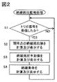
- FIG. 2 is a flowchart showing an insulation resistance monitoring process executed by the processing device 10 of FIG.
- step S11 the processing device 10 determines whether or not the communication device 18 has received the trigger signal from the control device 9. If YES, the process proceeds to step S12, and if NO, the process repeats step S11.
- step S12 the insulation resistance calculator 11 calculates the current insulation resistance value, and displays the calculated insulation resistance value on the display device 16.
- step S13 the insulation resistance predictor 12 calculates the insulation resistance prediction value, and displays the calculated insulation resistance prediction value on the display device 16.
- step S14 the insulation life predictor 13 calculates the insulation life prediction value, and displays the calculated insulation life prediction value on the display device 16.
- the insulation resistance value, the insulation resistance predicted value, and the insulation life can be calculated in a predetermined time cycle. can.
- FIG. 3 is a diagram for explaining a calculation example of the insulation resistance predicted value and the insulation life in steps S13 to S14 of FIG.
- the insulation resistance predictor 12 calculates the speed and acceleration at which the insulation resistance value changes with time, and calculates the insulation resistance prediction value based on the insulation resistance value, speed, and acceleration.
- the horizontal axis in FIG. 3 indicates the time t represented by the parameter n.
- t (n) indicates the present time, t (n-1), t (n-2), ... Indicates the past time point when the insulation resistance value was calculated, and t (n + 1), t (n + 2), ... Indicates insulation. Indicates a future point in time when the predicted resistance is calculated.
- the unit time ⁇ t (n) for calculating the velocity and acceleration of the insulation resistance value is defined by the following equation.
- ⁇ t (n) t (n) -t (n-1)
- the unit time ⁇ t (n) may be set to, for example, several days, several weeks, or several months.
- the time point at which the multiple of the unit time ⁇ t (n) is added to the current time point t (n) is set as the future time point t (n + 1), t (n + 2), ...
- the vertical axis in FIG. 3 shows the insulation resistance value and the insulation resistance predicted value.
- R (n) indicates the current insulation resistance value, R (n-1), R (n-2), ... Indicates the past insulation resistance value, and R (n + 1), R (n + 2), ... Is calculated.
- the future insulation resistance value to be calculated that is, the predicted insulation resistance value is shown.
- K indicates a predetermined threshold value of insulation resistance. As described above, the threshold value K may be set to, for example, a value determined by laws and regulations, or may be set to a value obtained by adding a predetermined margin to the value determined by laws and regulations.
- V (n-1) (R (n-2) -R (n-2)) / (t (n-1) -t (n-2))
- V (n) (R (n-1) -R (n)) / ⁇ t (n)
- the acceleration A (n) of the insulation resistance value is calculated by the following equation.
- a (n) V (n) -V (n-1)
- the velocity prediction value V (n + 1) indicating the velocity of the insulation resistance value at the future time point t (n + 1) is calculated by the following equation.
- V (n + 1) V (n) + A (n)
- the insulation resistance prediction value R (n + 1) at the future time point t (n + 1) is calculated by the following equation.
- R (n + 1) R (n)-(V (n + 1) ⁇ ⁇ t (n))
- the speed prediction value V (n + 2) and the insulation resistance prediction value R (n + 2) at the future time point t (n + 2) are calculated by the following equations.
- V (n + 2) V (n + 1) + A (n)
- R (n + 2) R (n + 1)-(V (n + 2) ⁇ ⁇ t (n))
- V (n + i) V (n + i-1) + A (n)
- R (n + i) R (n + i-1)-(V (n + i) ⁇ ⁇ t (n))
- the predicted insulation resistance value R (n + i-1) at the time point t (n + i-1) is larger than the threshold value K, and the predicted insulation resistance value R (n + i) at the time point t (n + i) is equal to or less than the threshold value K. Then, the insulation life D (n) at the present time t (n) is calculated by the following equation.
- the insulation resistance predictor 12 has current and past insulation resistance values R (n), R (n-1), R (n-2), calculated by the insulation resistance calculator 11. Based on ..., the predicted insulation resistance values R (n + 1), R (n + 2), ..., Which indicate the future insulation resistance values, can be calculated.
- the insulation resistance predictor 12 calculates the speed and acceleration at which the insulation resistance value changes with time, and calculates the insulation resistance prediction values R (n + 1), R (n + 2), ... Based on the insulation resistance value, speed, and acceleration. calculate.
- the insulation life predictor 13 has an insulation life D (n) indicating the remaining period until the insulation resistance predicted value becomes the threshold value K or less based on the insulation resistance predicted values R (n + 1), R (n + 2), ... Can be calculated.
- FIG. 4 is a diagram for explaining other calculation examples of the insulation resistance predicted value and the insulation life in steps S13 to S14 of FIG.
- the insulation resistance predictor 12 calculates the speed, acceleration, and jerk at which the insulation resistance value changes with time, and predicts the insulation resistance based on the insulation resistance value, speed, acceleration, and jerk. Calculate the value.
- the time derivative of the acceleration of the insulation resistance value that is, the jerk J (n) is calculated by the following equation.
- the velocity prediction value V (n + 1) indicating the velocity of the insulation resistance value at the future time point t (n + 1) is obtained.
- V (n + 1) V (n) + A (n) + J (n)
- the acceleration A (n + 1) at the future time point t (n + 1) is calculated by the following equation.
- V (n + 2) V (n + 1) + A (n + 1) + J (n)
- the predicted insulation resistance values R (n + 1) and R (n + 2) are calculated in the same manner as in the case of FIG.
- V (n + i) V (n + i-1) + A (n + i-1) + J (n)
- R (n + i) R (n + i-1)-(V (n + i) ⁇ ⁇ t (n))
- the insulation life D (n) at the present time t (n) is calculated by the following equation as in the case of FIG.
- the insulation resistance predictor 12 has current and past insulation resistance values R (n), R (n-1), R (n-2), calculated by the insulation resistance calculator 11. Based on ..., the predicted insulation resistance values R (n + 1), R (n + 2), ..., Which indicate the future insulation resistance values, can be calculated.
- the insulation resistance predictor 12 calculates the speed, acceleration, and jerk at which the insulation resistance value changes with time, and the insulation resistance prediction value R (n + 1), based on the insulation resistance value, speed, acceleration, and jerk. R (n + 2), ... Can be calculated.
- the insulation life predictor 13 has an insulation life D (n) indicating the remaining period until the insulation resistance predicted value becomes the threshold value K or less based on the insulation resistance predicted values R (n + 1), R (n + 2), ... Can be calculated.
- the insulation resistance predicted value and the insulation life can be calculated with higher accuracy than in the case of FIG.
- the display device 16 may display the temporal change of the insulation resistance predicted value from the present time to the time when the insulation resistance predicted value becomes equal to or less than the threshold value.
- the display device 16 may display a graph showing the predicted insulation resistance value with respect to time. By displaying such a graph, the user can recognize the tendency of deterioration of the insulation resistance.
- the insulation resistance value of the object to be measured is considered to gradually decrease as time passes from the start of use.
- the insulation resistance value may temporarily increase due to vibration or the like. If the insulation life is calculated based on such a temporarily increased insulation resistance value, the insulation life may be calculated longer than the actual value.
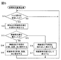
- FIG. 5 is a flowchart showing a modified example of the insulation resistance monitoring process executed by the processing device 10 of FIG.
- step S11 the processing device 10 determines whether or not the communication device 18 has received the trigger signal from the control device 9. If YES, the process proceeds to step S12, and if NO, the process repeats step S11.
- step S12 the insulation resistance calculator 11 calculates the current insulation resistance value, and displays the calculated insulation resistance value on the display device 16.
- step S13 the insulation resistance predictor 12 increases the insulation resistance value R (n) at the current time t (n) from the insulation resistance value R (n-1) calculated at the immediately preceding time point t (n-1). It is determined whether or not the test has been performed, and if YES, the process proceeds to step S16, and if NO, the process proceeds to step S14.
- step S14 the insulation resistance predictor 12 calculates the insulation resistance prediction value, stores the calculated insulation resistance prediction value in the storage device 14, and displays the calculated insulation resistance prediction value on the display device 16. ..
- step S15 the insulation life predictor 13 calculates the insulation life prediction value, stores the calculated insulation life in the storage device 14, and displays the calculated insulation life prediction value on the display device 16.
- step S16 the insulation resistance predictor 12 reads the insulation resistance prediction value from the storage device 14 and displays it on the display device 16.
- step S17 the insulation life predictor 13 reads the insulation life from the storage device 14 and displays it on the display device 16.
- the insulation resistance predictor 12 and the insulation life predictor 13 also execute steps S16 to S17 instead of steps S14 to S15 when the insulation resistance value R (n) is equal to the insulation resistance value R (n-1). You may. As a result, the amount of calculation of the insulation resistance predictor 12 and the insulation life predictor 13 can be reduced.
- the insulation resistance predictor 12 when the current insulation resistance value is higher than the insulation resistance value calculated at the time immediately preceding the current time, the insulation resistance predictor 12 is calculated before the insulation resistance value is increased.
- the predicted insulation resistance value is displayed on the display device 16, and the insulation life predictor 13 sets the insulation life calculated before the insulation resistance value increases as the current insulation life. As a result, it is possible to reduce errors in the predicted insulation resistance value and the insulation life due to the temporary increase in the insulation resistance value.
- the insulation resistance predicted value can be calculated based on the current and past insulation resistance values, and the insulation life can be calculated based on the insulation resistance predicted value. Therefore, the insulation resistance monitoring device 8 can monitor the state of the insulation resistance so that it is easier to make a maintenance plan for the object to be measured than before.
- the output device that outputs the calculated insulation life is not limited to the display device 16, and may include a device that outputs aurally such as a speaker, or may include a remote device connected via a communication line.
- the insulation resistance monitoring device 8 may be connected to any other object to be measured instead of the three-phase motor 3.
- the object to be measured includes, for example, a power supply device, a timer, a relay, a shared socket, a DIN rail, a waterproof cover, a temperature controller, a switch, and the like.
- the insulation resistance monitoring device may be configured to generate an alarm signal when the speed at which the insulation resistance value changes with time exceeds a predetermined threshold value.
- the insulation resistance monitoring device sets the insulation resistance value specified by law as the lower limit, sets the insulation resistance value first measured after starting the insulation resistance monitoring process as the upper limit, and sets the upper limit and lower limit.
- a value that divides the interval between the values at a predetermined ratio may be set as the threshold value of the insulation resistance value.
- the insulation resistance monitoring device monitors the insulation resistance of the object to be measured.
- the insulation resistance calculator 11 calculates the insulation resistance value of the object to be measured.
- the insulation resistance predictor 12 calculates an insulation resistance prediction value indicating a future insulation resistance value based on the current and past insulation resistance values calculated by the insulation resistance calculator 11.
- the insulation life predictor 13 calculates the insulation life indicating the remaining period until the insulation resistance predicted value becomes equal to or less than the threshold value based on the insulation resistance predicted value.
- the output device notifies the insulation life.
- the insulation resistance predictor 12 calculates the speed and acceleration at which the insulation resistance value changes with time, and insulates based on the insulation resistance value, speed, and acceleration. Predicted resistance may be calculated.
- the insulation resistance predictor 12 calculates the speed, acceleration, and jerk at which the insulation resistance value changes with time, and the insulation resistance value, speed, acceleration, and so on. And the predicted value of insulation resistance may be calculated based on the jerk.
- the insulation life predictor 13 when the current insulation resistance value increases from the insulation resistance value calculated at the time immediately preceding the current time, the insulation life predictor 13 has an insulation resistance value.
- the insulation life calculated before the increase may be set as the current insulation life.
- the insulation resistance calculator 11 may calculate the insulation resistance value of the object to be measured in response to a control signal from the outside of the insulation resistance monitoring device 8. ..
- the output device may include a display device 16.
- the display device 16 may display the insulation life, the current insulation resistance value, and the temporal change of the insulation resistance predicted value from the present time to the time when the insulation resistance predicted value becomes equal to or less than the threshold value.
- the insulation resistance monitoring device may further include an alarm 17 for notifying that the current insulation resistance value is below the threshold value.
- the insulation resistance monitoring device it is possible to monitor the state of insulation resistance so that it is easier to make a maintenance plan for the object to be measured than before.
Landscapes
- Physics & Mathematics (AREA)
- General Physics & Mathematics (AREA)
- Engineering & Computer Science (AREA)
- Power Engineering (AREA)
- Measurement Of Resistance Or Impedance (AREA)
- Testing Of Short-Circuits, Discontinuities, Leakage, Or Incorrect Line Connections (AREA)
- Testing Electric Properties And Detecting Electric Faults (AREA)
Applications Claiming Priority (2)
| Application Number | Priority Date | Filing Date | Title |
|---|---|---|---|
| JP2020-188196 | 2020-11-11 | ||
| JP2020188196A JP7589509B2 (ja) | 2020-11-11 | 2020-11-11 | 絶縁抵抗監視装置 |
Publications (1)
| Publication Number | Publication Date |
|---|---|
| WO2022102144A1 true WO2022102144A1 (ja) | 2022-05-19 |
Family
ID=81602220
Family Applications (1)
| Application Number | Title | Priority Date | Filing Date |
|---|---|---|---|
| PCT/JP2021/009902 Ceased WO2022102144A1 (ja) | 2020-11-11 | 2021-03-11 | 絶縁抵抗監視装置 |
Country Status (2)
| Country | Link |
|---|---|
| JP (1) | JP7589509B2 (https=) |
| WO (1) | WO2022102144A1 (https=) |
Cited By (1)
| Publication number | Priority date | Publication date | Assignee | Title |
|---|---|---|---|---|
| CN118444021A (zh) * | 2024-03-29 | 2024-08-06 | 北京和立智能科技有限公司 | 一种面向电动机的在线绝缘监测的实现方法及装置 |
Citations (8)
| Publication number | Priority date | Publication date | Assignee | Title |
|---|---|---|---|---|
| JPH10132877A (ja) * | 1996-10-31 | 1998-05-22 | N T T Facilities:Kk | 絶縁抵抗測定装置 |
| JP2000131363A (ja) * | 1998-10-20 | 2000-05-12 | Toshiba Corp | 電子装置の寿命診断方法及び装置 |
| JP2001037167A (ja) * | 1999-07-26 | 2001-02-09 | Mitsubishi Electric Building Techno Service Co Ltd | 回転機の絶縁寿命推定方法および回転機の絶縁寿命推定システム |
| JP2006098349A (ja) * | 2004-09-30 | 2006-04-13 | Mitsubishi Electric Building Techno Service Co Ltd | 高圧回転機の残存絶縁寿命推定システムおよび推定方法 |
| KR101330091B1 (ko) * | 2012-09-12 | 2013-11-18 | 이관우 | 운전중인 고전압 케이블의 수명 판정 방법 |
| JP2019163995A (ja) * | 2018-03-19 | 2019-09-26 | 株式会社東芝 | 劣化診断システム、抵抗値推定方法、およびコンピュータープログラム |
| JP2020003277A (ja) * | 2018-06-27 | 2020-01-09 | 三菱電機株式会社 | 受配電機器の短絡余寿命診断方法および短絡余寿命診断システム |
| JP2021043030A (ja) * | 2019-09-10 | 2021-03-18 | ファナック株式会社 | 機械学習装置、学習モデルの生成方法、絶縁抵抗推定装置及び制御装置 |
Family Cites Families (1)
| Publication number | Priority date | Publication date | Assignee | Title |
|---|---|---|---|---|
| US20190146022A1 (en) * | 2014-08-29 | 2019-05-16 | James J. Kinsella | Manual and automated non-destructive pre-startup testing for short-circuit and ground fault conditions in motor branch circuits |
-
2020
- 2020-11-11 JP JP2020188196A patent/JP7589509B2/ja active Active
-
2021
- 2021-03-11 WO PCT/JP2021/009902 patent/WO2022102144A1/ja not_active Ceased
Patent Citations (8)
| Publication number | Priority date | Publication date | Assignee | Title |
|---|---|---|---|---|
| JPH10132877A (ja) * | 1996-10-31 | 1998-05-22 | N T T Facilities:Kk | 絶縁抵抗測定装置 |
| JP2000131363A (ja) * | 1998-10-20 | 2000-05-12 | Toshiba Corp | 電子装置の寿命診断方法及び装置 |
| JP2001037167A (ja) * | 1999-07-26 | 2001-02-09 | Mitsubishi Electric Building Techno Service Co Ltd | 回転機の絶縁寿命推定方法および回転機の絶縁寿命推定システム |
| JP2006098349A (ja) * | 2004-09-30 | 2006-04-13 | Mitsubishi Electric Building Techno Service Co Ltd | 高圧回転機の残存絶縁寿命推定システムおよび推定方法 |
| KR101330091B1 (ko) * | 2012-09-12 | 2013-11-18 | 이관우 | 운전중인 고전압 케이블의 수명 판정 방법 |
| JP2019163995A (ja) * | 2018-03-19 | 2019-09-26 | 株式会社東芝 | 劣化診断システム、抵抗値推定方法、およびコンピュータープログラム |
| JP2020003277A (ja) * | 2018-06-27 | 2020-01-09 | 三菱電機株式会社 | 受配電機器の短絡余寿命診断方法および短絡余寿命診断システム |
| JP2021043030A (ja) * | 2019-09-10 | 2021-03-18 | ファナック株式会社 | 機械学習装置、学習モデルの生成方法、絶縁抵抗推定装置及び制御装置 |
Cited By (1)
| Publication number | Priority date | Publication date | Assignee | Title |
|---|---|---|---|---|
| CN118444021A (zh) * | 2024-03-29 | 2024-08-06 | 北京和立智能科技有限公司 | 一种面向电动机的在线绝缘监测的实现方法及装置 |
Also Published As
| Publication number | Publication date |
|---|---|
| JP2022077370A (ja) | 2022-05-23 |
| JP7589509B2 (ja) | 2024-11-26 |
Similar Documents
| Publication | Publication Date | Title |
|---|---|---|
| US8566047B2 (en) | Electrical anomaly detection method and system | |
| CN113299042B (zh) | 一种用于工业电器变频设备的安全预警系统 | |
| KR101272130B1 (ko) | 절연 모니터링 방법 및 장치 | |
| JP2016045793A (ja) | 設備の劣化状態判定システムおよび設備の劣化状態判定方法 | |
| KR102234242B1 (ko) | 발전소 전력설비의 재난 예방 상태감지 경보 시스템 | |
| CN112994248A (zh) | 一种配电网母线故障预警装置及方法 | |
| JP7244321B2 (ja) | 直流き電線の高抵抗地絡検出装置および検出方法 | |
| WO2022102144A1 (ja) | 絶縁抵抗監視装置 | |
| CN115885443B (zh) | 数字保护继电器及数字保护继电器监视系统 | |
| KR101264869B1 (ko) | 현장 감시 장치, 디지털 보호 계전기의 전력계통 감시 시스템 및 방법 | |
| JP7585722B2 (ja) | 絶縁抵抗監視装置 | |
| CN116997806A (zh) | 绝缘电阻监视装置 | |
| US11606022B2 (en) | Insulation deterioration monitoring apparatus and insulation deterioration monitoring method | |
| JP2013210246A (ja) | 抵抗値算出装置 | |
| CN117438012B (zh) | 一种复合绝缘子材料多因素老化试验分析系统 | |
| WO2015135580A1 (en) | Automatic calibration of a substation device | |
| JP2002243787A (ja) | 絶縁監視装置 | |
| CN114967571A (zh) | 基于互联网的充气柜远程监控系统 | |
| CN114300765B (zh) | 一种电池包监测方法和装置 | |
| JP3326209B2 (ja) | 電力用機器の運転保守支援システム | |
| CN204832401U (zh) | 一种电动车及其断开器导线柱故障监测装置 | |
| JP7259168B1 (ja) | 異常対応システム及び異常対応方法 | |
| CN216785382U (zh) | 一种电梯防雷监测装置 | |
| JP2021075146A (ja) | 動作時間監視装置 | |
| JP7278149B2 (ja) | 電線検査システム、及び、電線検査方法 |
Legal Events
| Date | Code | Title | Description |
|---|---|---|---|
| 121 | Ep: the epo has been informed by wipo that ep was designated in this application |
Ref document number: 21891394 Country of ref document: EP Kind code of ref document: A1 |
|
| NENP | Non-entry into the national phase |
Ref country code: DE |
|
| 122 | Ep: pct application non-entry in european phase |
Ref document number: 21891394 Country of ref document: EP Kind code of ref document: A1 |