WO2022101999A1 - 吸収性物品用不織布 - Google Patents
吸収性物品用不織布 Download PDFInfo
- Publication number
- WO2022101999A1 WO2022101999A1 PCT/JP2020/041969 JP2020041969W WO2022101999A1 WO 2022101999 A1 WO2022101999 A1 WO 2022101999A1 JP 2020041969 W JP2020041969 W JP 2020041969W WO 2022101999 A1 WO2022101999 A1 WO 2022101999A1
- Authority
- WO
- WIPO (PCT)
- Prior art keywords
- roll
- nonwoven fabric
- web
- convex
- fiber
- Prior art date
- Legal status (The legal status is an assumption and is not a legal conclusion. Google has not performed a legal analysis and makes no representation as to the accuracy of the status listed.)
- Ceased
Links
Images






Classifications
-
- A—HUMAN NECESSITIES
- A61—MEDICAL OR VETERINARY SCIENCE; HYGIENE
- A61F—FILTERS IMPLANTABLE INTO BLOOD VESSELS; PROSTHESES; DEVICES PROVIDING PATENCY TO, OR PREVENTING COLLAPSING OF, TUBULAR STRUCTURES OF THE BODY, e.g. STENTS; ORTHOPAEDIC, NURSING OR CONTRACEPTIVE DEVICES; FOMENTATION; TREATMENT OR PROTECTION OF EYES OR EARS; BANDAGES, DRESSINGS OR ABSORBENT PADS; FIRST-AID KITS
- A61F13/00—Bandages or dressings; Absorbent pads
- A61F13/15—Absorbent pads, e.g. sanitary towels, swabs or tampons for external or internal application to the body; Supporting or fastening means therefor; Tampon applicators
-
- A—HUMAN NECESSITIES
- A61—MEDICAL OR VETERINARY SCIENCE; HYGIENE
- A61F—FILTERS IMPLANTABLE INTO BLOOD VESSELS; PROSTHESES; DEVICES PROVIDING PATENCY TO, OR PREVENTING COLLAPSING OF, TUBULAR STRUCTURES OF THE BODY, e.g. STENTS; ORTHOPAEDIC, NURSING OR CONTRACEPTIVE DEVICES; FOMENTATION; TREATMENT OR PROTECTION OF EYES OR EARS; BANDAGES, DRESSINGS OR ABSORBENT PADS; FIRST-AID KITS
- A61F13/00—Bandages or dressings; Absorbent pads
- A61F13/15—Absorbent pads, e.g. sanitary towels, swabs or tampons for external or internal application to the body; Supporting or fastening means therefor; Tampon applicators
- A61F13/51—Absorbent pads, e.g. sanitary towels, swabs or tampons for external or internal application to the body; Supporting or fastening means therefor; Tampon applicators characterised by the outer layers of the pads
-
- A—HUMAN NECESSITIES
- A61—MEDICAL OR VETERINARY SCIENCE; HYGIENE
- A61F—FILTERS IMPLANTABLE INTO BLOOD VESSELS; PROSTHESES; DEVICES PROVIDING PATENCY TO, OR PREVENTING COLLAPSING OF, TUBULAR STRUCTURES OF THE BODY, e.g. STENTS; ORTHOPAEDIC, NURSING OR CONTRACEPTIVE DEVICES; FOMENTATION; TREATMENT OR PROTECTION OF EYES OR EARS; BANDAGES, DRESSINGS OR ABSORBENT PADS; FIRST-AID KITS
- A61F13/00—Bandages or dressings; Absorbent pads
- A61F13/15—Absorbent pads, e.g. sanitary towels, swabs or tampons for external or internal application to the body; Supporting or fastening means therefor; Tampon applicators
- A61F13/51—Absorbent pads, e.g. sanitary towels, swabs or tampons for external or internal application to the body; Supporting or fastening means therefor; Tampon applicators characterised by the outer layers of the pads
- A61F13/511—Topsheet, i.e. the permeable cover or layer facing the skin
-
- A—HUMAN NECESSITIES
- A61—MEDICAL OR VETERINARY SCIENCE; HYGIENE
- A61F—FILTERS IMPLANTABLE INTO BLOOD VESSELS; PROSTHESES; DEVICES PROVIDING PATENCY TO, OR PREVENTING COLLAPSING OF, TUBULAR STRUCTURES OF THE BODY, e.g. STENTS; ORTHOPAEDIC, NURSING OR CONTRACEPTIVE DEVICES; FOMENTATION; TREATMENT OR PROTECTION OF EYES OR EARS; BANDAGES, DRESSINGS OR ABSORBENT PADS; FIRST-AID KITS
- A61F13/00—Bandages or dressings; Absorbent pads
- A61F13/15—Absorbent pads, e.g. sanitary towels, swabs or tampons for external or internal application to the body; Supporting or fastening means therefor; Tampon applicators
- A61F13/51—Absorbent pads, e.g. sanitary towels, swabs or tampons for external or internal application to the body; Supporting or fastening means therefor; Tampon applicators characterised by the outer layers of the pads
- A61F13/514—Backsheet, i.e. the impermeable cover or layer furthest from the skin
-
- B—PERFORMING OPERATIONS; TRANSPORTING
- B32—LAYERED PRODUCTS
- B32B—LAYERED PRODUCTS, i.e. PRODUCTS BUILT-UP OF STRATA OF FLAT OR NON-FLAT, e.g. CELLULAR OR HONEYCOMB, FORM
- B32B5/00—Layered products characterised by the non- homogeneity or physical structure, i.e. comprising a fibrous, filamentary, particulate or foam layer; Layered products characterised by having a layer differing constitutionally or physically in different parts
- B32B5/22—Layered products characterised by the non- homogeneity or physical structure, i.e. comprising a fibrous, filamentary, particulate or foam layer; Layered products characterised by having a layer differing constitutionally or physically in different parts characterised by the presence of two or more layers which are next to each other and are fibrous, filamentary, formed of particles or foamed
- B32B5/24—Layered products characterised by the non- homogeneity or physical structure, i.e. comprising a fibrous, filamentary, particulate or foam layer; Layered products characterised by having a layer differing constitutionally or physically in different parts characterised by the presence of two or more layers which are next to each other and are fibrous, filamentary, formed of particles or foamed one layer being a fibrous or filamentary layer
- B32B5/26—Layered products characterised by the non- homogeneity or physical structure, i.e. comprising a fibrous, filamentary, particulate or foam layer; Layered products characterised by having a layer differing constitutionally or physically in different parts characterised by the presence of two or more layers which are next to each other and are fibrous, filamentary, formed of particles or foamed one layer being a fibrous or filamentary layer another layer next to it also being fibrous or filamentary
-
- D—TEXTILES; PAPER
- D04—BRAIDING; LACE-MAKING; KNITTING; TRIMMINGS; NON-WOVEN FABRICS
- D04H—MAKING TEXTILE FABRICS, e.g. FROM FIBRES OR FILAMENTARY MATERIAL; FABRICS MADE BY SUCH PROCESSES OR APPARATUS, e.g. FELTS, NON-WOVEN FABRICS; COTTON-WOOL; WADDING ; NON-WOVEN FABRICS FROM STAPLE FIBRES, FILAMENTS OR YARNS, BONDED WITH AT LEAST ONE WEB-LIKE MATERIAL DURING THEIR CONSOLIDATION
- D04H1/00—Non-woven fabrics formed wholly or mainly of staple fibres or like relatively short fibres
- D04H1/40—Non-woven fabrics formed wholly or mainly of staple fibres or like relatively short fibres from fleeces or layers composed of fibres without existing or potential cohesive properties
- D04H1/54—Non-woven fabrics formed wholly or mainly of staple fibres or like relatively short fibres from fleeces or layers composed of fibres without existing or potential cohesive properties by welding together the fibres, e.g. by partially melting or dissolving
-
- D—TEXTILES; PAPER
- D06—TREATMENT OF TEXTILES OR THE LIKE; LAUNDERING; FLEXIBLE MATERIALS NOT OTHERWISE PROVIDED FOR
- D06C—FINISHING, DRESSING, TENTERING OR STRETCHING TEXTILE FABRICS
- D06C23/00—Making patterns or designs on fabrics
- D06C23/04—Making patterns or designs on fabrics by shrinking, embossing, moiréing, or crêping
Definitions
- the present invention relates to a non-woven fabric for absorbent articles.
- Non-woven fabric is often used for absorbent articles such as diapers. Techniques for imparting various functions to this non-woven fabric have been developed.
- Patent Document 1 describes a non-woven fabric in which one surface of the front and back surfaces can move 5 mm or more with respect to the other surface.
- a fiber web in which fibers are unfused together hereinafter, also referred to as an unfused web
- Patent Document 2 describes a technique of forming an unfused web with unevenness using a gas injection means such as an air jet nozzle and fixing the formed uneven shape by heat treatment to obtain an uneven nonwoven fabric.
- Patent Documents 3 and 4 describe a technique for shaping a non-woven fabric formed by fusing fibers to each other into an uneven shape. It is described that the bottom portion of the recess is pressed to make the bottom portion rigid or compacted at the time of shaping the unevenness of the nonwoven fabric. Further, Patent Document 5 describes a technique for three-dimensional shaping using a web having a low degree of entanglement.
- Patent Document 6 a web that is not three-dimensionally structured is stretched while being engaged by a male roll having a large number of male molds and a female roll having a large number of depressions, and then by a hot roll or a pin roll. The technique of cleaving is described.
- the present invention is a nonwoven fabric for absorbent articles having a plurality of convex portions and concave portions located between the convex portions, and the concave portions have an embossed portion and a fusion portion between fibers, and the periphery of the embossed portion.
- the present invention provides a non-woven fabric for an absorbent article, wherein the ratio of the fused portion having a long fusion length between fibers rising on the convex portion side is 5% or more.
- the present invention is a method for manufacturing a non-woven fabric for absorbent articles having a plurality of protrusions and recesses located between the protrusions, and has a concave-convex shape having a plurality of protrusions and depressions and capable of meshing with each other.
- the unfused web using fibers is subjected to uneven shaping processing to form a meshing shaped web, and at the same time as the shaping step or after the shaping step.
- An embossed heat fusion step that joins some or all of the fibers at the bottom of the recesses of the meshing shaped web at some or all of the protrusions or some or all of the recesses.
- a non-woven fabric for absorbent articles including an embossed crimping step and a heat flow fusion step of forming a fused portion at a fiber intersection with a heated fluid on a web embossed by the embossed heat fusion step or the embossed crimping step.
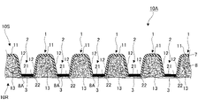
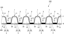
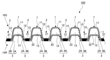
- FIG. 1 shows typically another embodiment (two-layer structure and closed hollow structure) of the nonwoven fabric for absorbent articles which concerns on this invention.
- FIG. 1 shows typically another embodiment (two-layer structure and closed hollow structure) of the nonwoven fabric for absorbent articles which concerns on this invention.
- FIG. 1 is plan views schematically showing one embodiment (Specific Examples 1 to 3) of the arrangement pattern of the convex portion and the concave portion in the non-woven fabric for absorbent articles according to the present invention from the surface side.
- .. are plan views schematically showing another embodiment (Specific Examples 4 to 6) of the arrangement pattern of the convex portion and the concave portion in the nonwoven fabric for absorbent articles according to the present invention from the surface side. be.
- (A) to (D) are plan views schematically showing another embodiment (Specific Examples 7 to 10) of the arrangement pattern of the convex portion and the concave portion in the nonwoven fabric for absorbent articles according to the present invention from the surface side.
- (A) and (B) are plan views schematically showing another embodiment (Specific Examples 11 and 12) of the arrangement pattern of the convex portion and the concave portion in the nonwoven fabric for absorbent articles according to the present invention from the surface side.
- (A) to (C) are plan views schematically showing another embodiment (Specific Examples 13 to 15) of the arrangement pattern of the convex portion and the concave portion in the nonwoven fabric for absorbent articles according to the present invention from the surface side. be.
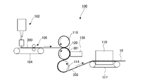
- the first roll and the second roll when the shaping step (step (I)) and the embossing heat fusion step or the embossing crimping step (step (II)) are performed at the same time.
- step (II) the protrusion of the second roll when the embossing heat fusion step or the embossing crimping step (step (II)) is sequentially performed after the shaping step (step (I)).
- step (II) the recess of the second roll when the embossing heat fusion step or the embossing crimping step (step (II)) is sequentially performed after the shaping step (step (I)).
- the present invention relates to a non-woven fabric for absorbent articles, which has a good cushioning property accompanied by a thickness deformation, yet an appropriate thickness tends to remain when pressed, and has a soft texture.
- Patent Documents 1 to 6 The non-woven fabric to which the uneven shape is given by the technique described in Patent Documents 1 to 6 is easily deformed in the thickness direction (also referred to as thickness deformation) and has good cushioning property.
- thickness deformation thickness direction
- Patent Documents 5 and 6 do not suggest fusion formation at fiber intersections after shaping, and there is room for improvement in obtaining a good texture due to fluffing and insufficient thickness recovery after compression.
- the non-woven fabric for absorbent articles of the present invention has a good cushioning property with thickness deformation, but an appropriate thickness tends to remain when pressed, and has a soft texture.
- the nonwoven fabric for absorbent articles of the present invention can be used as various constituent members of absorbent articles.
- a surface material that comes into contact with the skin a back surface material on the clothing side, a core wrap sheet that is a surface covering material in an absorber interposed between the surface material and the back surface material, an absorption sheet that constitutes the absorber, and a three-dimensional leakage-proof gather member.
- it can be used as a sublayer or the like interposed between the surface material and the absorber.
- the absorbent article has a fastening tape or a wing portion, it can also be used as a base sheet for the fastening tape, a landing tape sheet with which the fastening tape engages, a base sheet for the wing portion, and the like.
- the absorbent article using the non-woven fabric for the absorbent article of the present invention may include various articles for the purpose of absorbing body fluid without particular limitation. Examples include diapers, menstrual napkins, panty liners, urine absorbing pads and the like.
- the non-woven fabric 10 for absorbent articles of the present embodiment (hereinafter, also simply referred to as the non-woven fabric 10) has a plurality of convex portions 1 and concave portions 2 located between the convex portions 1 and 1.
- the convex portion 1 is a portion protruding toward one surface side of the front and back surfaces of the nonwoven fabric 10, and the concave portion 2 is a recessed portion sandwiched between the protruding convex portions 1 and 1 on the one surface side. be.
- the convex portions 1 and the concave portions 2 are alternately arranged in the plane direction of the nonwoven fabric 10 to form an uneven surface on one surface side of the nonwoven fabric 10.
- the one surface side on which the convex portion 1 protrudes is referred to as a front surface side 10S, and the opposite surface side is referred to as a back surface side 10R.
- the front surface side 10S is directed to the skin surface side of the absorbent article
- the back surface side 10R is directed to the non-skin surface side of the absorbent article.
- the convex portion 1 is in the range of 1/4 of the surface side 10S of the initial thickness (at 0.5 gf / cm 2 load) (T0) before pressing, which will be described later, with respect to the thickness direction of the nonwoven fabric 10.
- the recess 2 is in the range of 1/4 of the back surface side 10R of the initial thickness. 1/4 of the initial thickness (at 0.5 gf / cm 2 load) (T0) between the convex portion 1 and the concave portion 2 before pressing, which will be described later, with respect to the thickness direction of the nonwoven fabric 10.
- the fiber layer on the surface side 10A within the range of 3/4 from the position (the surface of the recess 2) is referred to as an intermediate wall portion 122.
- the convex portion 1 has a top portion 11 and a side wall portion 121 descending from the top portion 11, and the concave portion 2 has a bottom portion 21 and a side wall portion 123 rising from the bottom portion 21.
- the intermediate wall portion 122, the side wall portion 121 of the convex portion 12, and the side wall portion 123 of the concave portion 2 form a seamless fiber layer in the thickness direction of the nonwoven fabric 10.
- the intermediate wall portion 122, the side wall portion 121 of the convex portion 12, and the side wall portion 123 of the concave portion 2 may be collectively referred to as the wall portion 12.
- the inside 13 of the convex portion 1 is hollow.
- the "inside 13 of the convex portion 1" is not limited to the region of the back surface side 10R surrounded by the top portion 11 and the side wall portion 121, but is the region of the back surface side 10R of the convex portion 1 and is the region of the convex portion 1. It means a region surrounded by the top portion 11, the side wall portion 121, the intermediate wall portion 122, and the side wall portion 123 of the recess 2 adjacent to the convex portion 1. In other words, at the arrangement position of the convex portion 1, the region on the back surface side 10R of the convex portion 1 over the entire thickness direction of the nonwoven fabric 10 is referred to as "inside 13 of the convex portion 1".
- the inside 13 of the convex portion 1 is hollow, it is surrounded by the top portion 11 and the side wall portion 121 of the convex portion 1, the intermediate wall portion 122, and the side wall portion 123 of the concave portion 2 adjacent to the convex portion 1. It means that the area is a space that is not filled with fibers.
- “hollow” means a space that is not substantially filled with fibers inside the back surface side 10R of the convex portion 1, and specifically, the fiber density is less than 5 fibers / mm 2 .
- “Solid” means that the inside of the back surface side 10R of the convex portion 1 is substantially filled with fibers, and specifically, it means that the fiber density is 5 fibers / mm 2 or more. ..
- the fiber density can be measured by the following method by observing the cross section of the nonwoven fabric 10.
- the non-woven fabric 10 is cut in the thickness direction so as to pass through the top 11 of the convex portion 1 to be measured.
- a scanning electron microscope (SEM) is used to magnify the cut surface and count the cross sections of the cut fibers in a given area of the cut surface. The magnified observation is adjusted to a magnification (150 times or more and 500 times or less) that can measure about 30 to 60 fiber cross sections. Next, it is converted into the number of cross sections of the fiber per 1 mm 2 , and this is used as the fiber density (book / mm 2 ). The measurement results at three locations are averaged to obtain the fiber density of the sample.
- Various devices can be used as the scanning electron microscope (SEM). For example, JCM-5100 (trade name) manufactured by JEOL Ltd. may be mentioned.
- a space portion 22 opened to the surface side 10S is arranged on the surface side 10S of the recess 2.
- the “surface side 10S of the concave portion 2” means a region surrounded by the bottom portion 22 and the side wall portion 123 of the concave portion 2, the intermediate wall portion 122, and the side wall portion 121 of the convex portion 1 adjacent to the concave portion 2.
- the region on the surface side 10S of the recess 2 over the entire thickness direction of the nonwoven fabric 10 is referred to as "the surface side 10S of the recess 1." Therefore, in the space portion 22 opened to the surface side 10S, the region surrounded by the bottom portion 22 and the side wall portion 123 of the concave portion 2, the intermediate wall portion 122, and the side wall portion 121 of the convex portion 1 adjacent to the concave portion 2 is made of fibers. It means an unfilled space.
- the nonwoven fabric 10 holds the space portion in the area on both sides of the back surface side 10R which is the inside 13 of the convex portion 1 and the front surface side 10S of the concave portion 2, and the fibers of the convex portion 1, the intermediate wall portion 122 and the concave portion 2 are held.
- the layer has an uneven shape that meanders up and down in the thickness direction.
- the outer shape of the surface side 10S of the convex portion 11 can be various shapes that can disperse and absorb a load such as a pressing force applied to the top portion 1 and give a soft texture when touching the skin.
- a flat rectangular parallelepiped or a quadrangular pyramid with rounded ridges as a whole can be mentioned.
- the present invention is not limited to this, and the base of the convex portion 1 may be circular, elliptical, pentagonal, hexagonal, octagonal, etc. in a plane, and in the thickness direction, a dome shape having the mouth of an octopus trap as the base. It can be hemispherical or elliptical.
- a dome shape is preferable because it is structurally difficult to collapse.
- the convex portion 1 has a dome shape
- the top portion 11 has a spherical shape without corners, and the top portion 11 and the side wall portion 121 form a curved surface without a boundary.
- the inside 13 of the convex portion 1 is not limited to the case where it is hollow as shown in FIG. 1, and the inside 13 may be a solid filled with fibers. Whether it is “hollow” or “solid” is determined by the fiber density (book / mm 2 ) defined above.
- the recess 2 has an embossed portion 3 and a fused portion between fibers.
- the embossed portion 3 is arranged at the bottom portion 21 of the recess 2.
- the "embossed portion” means a portion where the fiber layer at the bottom 21 is pressed by embossing and the fibers are pressure-fused or crimped. In the embossed portion 3, the fibers are made denser than the surroundings.
- the "fused portion between fibers” means a portion where the fibers are fused without being crushed, unlike the "pressurized fusion” or “crimping” portion shown below.
- Pressure fusion means that the resin of at least one fiber at the bonding interface between fibers is melted by pressure and heat (self-heating due to intermolecular friction or compression or external heating) and bonded to the other fiber. (This pressure fusion process is also called embossed heat fusion). In pressure fusion, pressure is applied to the fibers from the outside by at least pinching. Since some resins have a lower melting point of the resin constituting the fiber due to the pressure, the heating temperature (surface temperature of the processing roll or the like) may be lower than the melting point of the resin under unloaded load.
- the fibers are pressure-fused means that the fibers are crushed and deformed as compared with other parts by observing the cross section of the nonwoven fabric with a scanning electron microscope, and at least one of the resins constituting the fibers is resin. Is melted and does not have a fiber morphology.
- the degree to which the fiber is crushed and deformed at least a part of the cross section of the boundary portion between the embossed portion and the fiber (also referred to as the embossed boundary portion) is the fiber cross section (in the longitudinal direction of the fiber) as compared with the non-embossed portion.
- the average flatness (ratio of long side / short side) of (cross section in the vertical direction) is 20% or more higher.
- the amount of increase (%) in the average flattening is calculated as [(average flattening at the embossed boundary-average flattening at the non-embossed part) / average flattening at the non-embossed part] ⁇ 100.
- the outer circumference of the fiber cross section is not circular or elliptical, the long side and the short side are obtained by approximating the outer circumference of the fiber to an elliptical shape having the same cross-sectional area.
- having the above-mentioned fiber morphology means that the ratio (former / latter) of the length of the fiber and the diameter (calculated as a perfect circle) obtained from the cross-sectional area of the fiber is 300 times or more.
- the fiber cannot be distinguished from the outer peripheral surface of another fiber by melting at least a part of the melted portion, it is assumed that the fiber is melted and does not have a fiber morphology.
- resins such as composite fibers
- at least one kind of resin melts and the outer peripheral surface of the fiber and the other fibers are used. If the boundary with the outer peripheral surface cannot be determined, it is considered that the fiber is melted and does not have a fiber morphology.
- “Crimping” means that the resin is not melted by heat or pressure and the fiber adheres to the other fiber (this crimping process is also referred to as embossed crimping). Even in crimping, pressure is applied from the outside by at least pinching. The force with which the fibers adhere (also referred to as adhesion) may be strong enough to convey the sheet. By observing the cross section of the non-woven fabric with a scanning electron microscope, the fibers are crushed and deformed compared to other parts, and the contact length is crimped at the fiber cross section at the contact point between the fibers. It can be confirmed that it is more than the part that is not done. The degree to which the fibers are crushed and deformed is the same as that of pressure fusion.
- the fiber is not melted by being able to discriminate the boundary between the outer peripheral surface of the fiber and the outer peripheral surface of another fiber at the crimping portion. Further, it is preferable that the contact length per contact point between the fibers is increased by 10% or more on average as compared with the portion where the fibers are not crimped.
- the amount of increase (%) in the contact length is calculated as [(contact length of the outer circumference of the fiber at the crimped part-contact length at the non-crimped part) / contact length at the non-crimped part] ⁇ 100. be able to.
- the sample is embedded in resin (the constituent fibers such as epoxy resin and acrylic resin are hardened with a resin that does not easily swell or deform), and then the cross-section is formed with a sharp blade.
- the embossed portion 3 as an example, the fibers are in a state along the plane direction of the nonwoven fabric 10, and tend to be crushed and flattened or formed into a film. Further, the embossed portion 3 has a higher fiber density than the other portions. It is preferable that such an embossed portion 3 has a flat plate shape with a compressed thickness. In FIG. 1, the embossed portion 3 is shown in black for convenience so that its existence can be grasped (hereinafter, the same applies to other drawings).
- the embossed portion 3 is arranged on a part or all of the bottom portion 21.
- the area of the embossed portion 3 in the bottom portion 21 is preferably 50% or more, more preferably 80% or more of the area of the entire bottom portion 21 from the viewpoint of maintaining the shape of the convex portion 1. Further, the embossed portions 3 may be arranged continuously or intermittently so as to surround the convex portions 1 when viewed with the convex portions 1 as a reference.
- the nonwoven fabric 10 when the nonwoven fabric 10 is incorporated as a constituent member such as a surface material of an absorbent article, the permeation of the body fluid impregnated from the convex portion 1 is difficult to be closed by the embossed portion 3, and the body fluid is formed in the vicinity of the embossed portion 3. It has the advantage of being hard to remain.
- the number of embossed portions 3 surrounding one convex portion 1 can be arbitrarily set, but it is preferable to arrange them intermittently in the range of 4 to 12.
- fused portion 4 having a long fused length between fibers that rises toward the convex portion 1 (enclosed by the ellipse of the alternate long and short dash line in FIG. 2). See the part).
- the “fused portion having a long fusion length” means a portion fused with a length of 10 times or more the fiber diameter, excluding the embossed portion 3 described above.
- the fibers are partially linearly fused (also referred to as linear fusion) along the fiber length.
- Such a line-fused "fused portion having a long fusion length” is a portion having a thickness equal to or larger than the fiber diameter of each of the fused fibers, and the fibers are separated from the fused portion. It can be divided as a part until branching. Further, the periphery of the "embossed portion 3" is a region from the surface of the embossed portion 3 to a certain height when viewed with the embossed portion 3 facing down and the convex portion 1 facing up in the thickness direction of the nonwoven fabric 10. Refers to R.
- the constant height means a range of up to 10% with respect to the height from the surface of the embossed portion 3 to the top 11 of the convex portion 1.
- the height range is 20 times the fiber diameter.
- the "fused portion having a long fusion length" exists in the region R of the above-mentioned constant height range in the fiber layer of the side wall portion 123 of the recess 2.
- the fused portion 4 having a long fusion length rises toward the convex portion 1 side instead of along the plane direction of the nonwoven fabric 10 as in the embossed portion 3, and is connected to the side wall portion 123 rising from the bottom portion 21 of the concave portion 2. It is included in the part to be used.
- the rising average angle of the fused portion 4 having a long fusion length is preferably 60 degrees or less with respect to the thickness direction.
- the fused portion 4 having a long fusion length defined above increases the bending strength of the side wall portion 123 of the recess 2 which is the lower end portion of the wall portion 12, and the convex portion 1 of the nonwoven fabric 10 is crushed. Produces an appropriate repulsive force when a load is applied.
- the fused portion can be formed by various heating fluids capable of fusing the fiber intersections of the web. Hot air (heated air, heating gas, etc.), steam, or the like is used as the heating fluid, and a fusion zone (also referred to as a fiber intersection fusion portion or a heat flow fusion portion) is formed at the fiber intersection.
- a fusion zone also referred to as a fiber intersection fusion portion or a heat flow fusion portion
- the fused portion at least one or more kinds of resins are once melted, flowed, and solidified to form the fused portion. It is preferable that the resins in the fused portion are of the same type in terms of increasing the strength of the fused portion, but the fused portion can be formed by flowing at least one of the resins.
- the fact that the fibers are flowing can be confirmed by comparing the cross-sectional shape of the fused portion with the fiber cross-sectional shape of the non-fused portion and confirming that they are not similar figures. Since the pressure applied to the fibers by the heating fluid is smaller than that of the embossing, the increase in the average flatness of the fiber cross section before and after the addition of the heating fluid is preferably less than 20%.
- the fused portion 4 having a long fusion length is a portion obtained by sequentially passing through each step shown in the manufacturing method described later. That is, by shaping the unfused web, which has a higher degree of freedom in the movement of the fibers than the non-woven fabric, by meshing, a portion where the fibers are aligned in the thickness direction, that is, an oriented portion is formed (unfused web). Is called a meshing shaped web). Next, by embossing the bottom of the concavely shaped fiber layer, the fibers at the bottom are consolidated, and the density of the fibers extending from the bottom in the thickness direction can be increased (the distance between the fibers is shortened).
- the fibers near the outer boundary of the embossed portion are oriented in the thickness direction and are maintained in a high-density state.
- a heating fluid is applied to the embossed web to form a fused portion at the fiber intersection to form a non-woven fabric, so that the fused length defined as described above is long around the embossed portion 3.
- the fused portion 4 is formed.
- the fiber intersection fusion portion is formed during the air-through processing in this order, so that it is melted around the embossed portion 3 as described above. It is difficult to form a fused portion having a long wearing length at a high ratio. Further, in the case where the unfused web is unevenly shaped as in another conventional technique, a fusion point is formed by heat treatment, and the non-woven fabric is embossed, the fibers are not densified around the embossed portion. Since the intersection fusion portion is formed, the embossing is performed in a state where the arrangement relationship between the fibers is fixed.
- the nonwoven fabric 10 of the present embodiment includes the fused portion 4 having a long fused length defined above, which cannot be obtained by the conventional processing step, at a high ratio as described later.
- the proportion of the fused portion 4 having a long fused length that rises toward the convex portion 1 is 5% or more around the embossed portion 3.
- This ratio is the "fused portion 4 having a long fusion length" in the total number of fused portions between fibers in the periphery of the embossed portion 3, that is, in the region R from the surface of the embossed portion 3 to a certain height.
- the ratio of the number of. As a result, the lower end portion of the wall portion 12 has sufficient bending strength, and the convex portion 1 is suppressed from being crushed (also referred to as sagging) when a load is applied, and the cushioning property is enhanced.
- the non-woven fabric 10 tends to remain thick under load while having the soft touch and flexibility of the non-woven fabric on the top 11. That is, the nonwoven fabric 10 has a good cushioning property accompanied by a thickness deformation, but tends to have an appropriate thickness when pressed, and has a soft texture. Further, when the nonwoven fabric 10 is used as a surface material for an absorbent article, in addition to the above effects, the absorption rate of body fluid is improved, and the effect of reducing liquid residue is enhanced.
- the ratio of the fused portion 4 having a long fusion length is 5% or more, preferably 10% or more, from the viewpoint of increasing the bending rigidity of the lower end portion of the wall portion 12 around the embossed portion 3.
- the ratio of the fused portion 4 having a long fusion length is preferably 70% or less, more preferably 50% or less, from the viewpoint of preventing the embossed portion 3 from becoming too hard and maintaining the texture.
- the non-woven fabric to be measured is cut from an absorbent article or the like with scissors or the like and sampled. If the non-woven fabric is bonded to another member, sampling is performed while the non-woven fabric is bonded to the other member. This non-woven fabric is placed in a non-loaded state with the convex portion facing up, and stored at a temperature of 23 ⁇ 2 ° C. and a humidity of 65 ⁇ 5% RH for 48 hours or more and 72 hours or less.
- the above sampled material is prepared into a size of 20 mm ⁇ 10 mm square.
- one side is cut on a line including the center of the embossed portion 3 to be observed with a sharp scissors or the like to a length of 20 mm with the embossed portion 3 as the center (cut line 1). If the distance between the embosses is 10 mm or more, cut with a length of 4 times the embossing pitch (cut line 1 side) x 2 times.
- the cut line 1 does not cut the target convex portion 1, but cuts the embossed portion 3 adjacent to the convex portion 1.
- the cut line 1 cuts the target convex portion 1.
- the cross-sectional sample on the cut line 1 is vapor-deposited with gold spatter (the vapor deposition time is the minimum time required for observation), the cross-section or the side surface of the unevenness is observed with a scanning electron microscope (SEM). Observe the surface side (wall surface 12) of the convex portion 1.
- SEM scanning electron microscope
- the central convex portion 1 arranged along the cut line 1 is targeted, and the surface of the embossed portion 3 is directed in the thickness direction from the boundary 3A of the surface side 10S of the embossed portion 3, that is, in the direction of the top 11 of the convex portion 1.
- the range R up to 10% of the height from to the top 11 of the convex portion 1 observation is performed at 50 times or more and 300 times or less depending on the fiber diameter (see FIG. 1).
- the width of the target range (observation range in the plane direction of the sheet) is the total width at the observation magnification.
- the height range is 20 times the fiber diameter. .. (5)
- the fused portion where the fibers are fused at the fiber intersection is marked.
- the value obtained by dividing the number of fused portions 4 having a fused length of 10 times or more the fiber diameter by the number of fused portions within the observation target range is multiplied by 100. Similarly, measurements are made at 10 different locations, and these values are averaged to determine the proportion (%) of the fused portions having a long fusion length around the embossed portion 3. Measure by observing at least 5 or more cross-section samples. Note the following points in the above measurement. (I) Whether it is a fused portion or not is a fused portion in which the fiber shape is different from that of the unfused portion at the fiber intersection and the fiber resin is considered to be fused. And.
- the average fluctuation value of the fiber diameter of the fibers constituting the convex portion 1 is preferably 30% or less, more preferably 20% or less, and 10%. The following is more preferable. Further, the upper limit is preferably unchanged, and is preferably 0% or more.
- the average fluctuation value of the fiber diameter is 30% or less, the number of partial neck-in points due to stretching etc. is reduced and the number of small fiber diameter parts is small, so that the cushioning property is good and the texture is excellent.
- a non-woven fabric is obtained.
- the strength of the fiber is increased, the convex portion 1 is less likely to be crushed (sag), and the thickness of the non-woven fabric is likely to remain.
- a non-woven fabric in which the arrangement relationship between fibers is fixed as in the conventional technique is unevenly shaped, the fibers between the fused portions at the fiber intersections are stretched, and a part having a small fiber diameter is formed like a dumbbell.
- the average fluctuation value becomes high.
- the dumbbell-shaped portion is small and the above-mentioned average fluctuation value is realized by sequentially passing through each of the above-mentioned unique steps.
- the average fiber diameter of the fibers constituting the convex portion 1 is preferably 5 ⁇ m or more when used as a surface material of an absorbent article from the viewpoint of reducing the amount of liquid remaining on the surface material after absorption of body fluid. 8 ⁇ m or more is more preferable, and 10 ⁇ m or more is further preferable.
- the average fiber diameter of the fibers constituting the convex portion 1 is preferably 30 ⁇ m or less, more preferably 25 ⁇ m or less, still more preferably 20 ⁇ m or less, from the viewpoint of improving the texture when in contact with the skin.
- the average fiber diameter can be measured by the following method. That is, the non-woven fabric 10 is observed from the surface on the convex portion 1 side with a scanning electron microscope (SEM). The fiber diameter that seems to be almost average within the observation range is obtained as the representative fiber diameter.
- the image is taken by focusing on the fiber on the upper side, that is, on the electron beam irradiation side.
- the fiber diameter of the fiber layer on the surface side 10S is measured.
- the thickness of the fiber in different fibers selected at random that is, the width in the direction perpendicular to the longitudinal direction of the fiber was measured at 10 points in the portion excluding the fused portion and the end portion of the fiber at the fiber intersection.
- the average value is taken as the fiber diameter.
- the average fiber diameter is obtained by averaging the values measured in the same manner for 5 different samples. If the fiber cross section is not circular, select 10 fibers that are perpendicular to the SEM screen by observing the cross section in the thickness direction of the non-woven fabric, obtain the cross-sectional area from the cross-sectional shape, and assume that it is circular.
- the fiber diameter is obtained from the diameter at the time of
- the average fluctuation value of the fiber diameter can be measured by the following method. That is, in the same manner as the measurement of the average fiber diameter, the width of the fiber at the thickest part of the fiber (perpendicular to the longitudinal direction of the fiber) in the portion excluding the fused portion and the end portion of the fiber at the fiber intersection per image. The width in the above direction is measured as D1, and the width of the fiber at the thinnest part of the fiber (width in the direction perpendicular to the longitudinal direction of the fiber) is measured as D2. From the obtained value, the fluctuation value of the fiber diameter is obtained as "(D1-D2) / average fiber diameter x 100 (%)".
- the average fluctuation value of the fiber diameter is obtained by averaging the values measured in the same manner for 5 different samples. For the thickest part and the thinnest part of the fiber, the peeling mark of the fused part is also measured.
- the cross-sectional area is measured at 10 points in the same manner as the measurement of the average fiber diameter, and the maximum value D1 and the minimum value D2 of the fiber are calculated from the diameter when the fiber is assumed to be circular. demand.
- the periphery of the embossed portion 3 has a higher proportion of the fused portion 4 having a long fusion length than the top portion 11 of the convex portion 1.
- the contrast between the flexibility and soft touch of the top portion 11 and the bending rigidity of the lower end portion of the wall portion 12 becomes clearer.
- the above-mentioned effect of the nonwoven fabric 10 can be further enhanced.
- the density of the fused portion formed at the fiber intersection is higher in the periphery of the embossed portion 3 than in the top portion 11 of the convex portion 1.
- the fused portion at the top portion 11 can be measured from the surface side 10S of the nonwoven fabric 10 by the same method as described above (measurement method for the ratio of the fused portion 4 having a long fused length).
- V1-V2 The difference (V1-V2) between the ratio of the fused portion 4 having a long fusion length around the embossed portion 3 (V1) and the proportion of the fused portion 4 having a long fusion length at the top 11 (V1) is From the viewpoint of clarifying the above contrast, 2% points or more are preferable, 5% points or more are more preferable, and 10% points or more are further preferable.
- the surface of the convex portion 1 (the surface of the top portion 11 of the convex portion 1) and the surface of the concave portion 2 (the bottom portion 21 of the concave portion 2) when viewed from a direction orthogonal to the protruding direction of the convex portion 1.
- the difference H1 in the average height from the surface is preferably 0.3 mm or more from the viewpoint of further enhancing the cushioning property of the nonwoven fabric 10, increasing the amount of deformation during pressing, and improving the soft texture.
- the above is more preferable, and 4 mm or more is further preferable.
- the difference H1 in the average height is preferably 20 mm or less, more preferably 12 mm or less, from the viewpoint of further increasing the resistance to crushing of the nonwoven fabric 10 due to pressure in the product package (easiness of remaining thickness at the time of pressing). , 8 mm or less is more preferable.
- Such a bulky convex portion 1 cannot be formed by general embossing (due to the thermal pressure of the convex roll and the flat roll), and each of the above-mentioned peculiar portions including the shaping step for the unfused web is included. It is preferable because it can be formed by going through the steps in order.
- the surface of the convex portion 1 is the surface of the top portion 11 of the convex portion 1
- the surface of the concave portion 2 is the surface of the bottom portion 21 of the concave portion 2. Therefore, the "difference in average height H1 between the surface of the convex portion 1 and the surface of the concave portion 2" is, in short, the average height of the convex portion 1 when the surface of the bottom portion 21 is used as a reference.
- the height of the surface of the convex portion 1, the height of the surface of the concave portion 2, and the difference H1 between the surface of the convex portion 1 and the surface of the concave portion 2 can be measured by the following method. That is, first, by measuring the compression of an automatic compression tester (KES FB3-AUTO-A (trade name) manufactured by Kato Tech Co., Ltd.), the convex portion 1 at the time of pressurizing 0.5 gf / cm 2 in the compression direction is included. The thickness of the non-woven fabric 10 is determined.
- KS FB3-AUTO-A automatic compression tester
- This thickness is obtained for each of a plurality of (for example, five) samples, and the average value thereof is defined as the average height T0 (mm) of the surface of the convex portion 1.
- the average height T0 of the surface of the convex portion 1 includes not only the convex portion 1 but also the thickness of the embossed portion 3 of the concave portion 2 and the thickness of the fiber layer if there is another fiber layer on the lower layer side. It has been.
- the nonwoven fabric 10 is cut with sharp scissors or the like, and the cut cross section is observed with a scanning electron microscope (SEM) to obtain the cross-sectional thickness of the recess 2 corresponding to the thickness of the embossed portion.
- SEM scanning electron microscope
- the cross-sectional thickness is obtained as the average distance between the two straight lines by drawing the average position where the fibers are present on each of the upper surface and the lower surface of the fiber layer with a straight line. If there is another fiber layer on the lower layer side, the thickness of the fiber layer is also included in the "cross-sectional thickness of the recess 2".
- the cross-sectional thickness is also obtained for each of the same number (for example, 5) of samples, and the average value thereof is defined as the average height H2 (mm) of the surface of the recess 2.
- the value obtained by subtracting the "average height H2 of the surface of the concave portion 2" from the “average height T0 of the surface of the convex portion 1" obtained in this way is used as the "surface of the convex portion 1 and the surface of the concave portion 2".
- the difference in average height of H1 is synonymous with the non-woven fabric thickness T0 under a load of 0.5 gf / cm 2 in (method for measuring compression characteristics) described later.
- the basis weight of the nonwoven fabric 10 is preferably 4 g / m 2 or more, more preferably 8 g / m 2 or more, and more preferably 12 g / m, from the viewpoint of making the convex portion 1 less likely to be crushed, that is, to further increase the ease with which the thickness remains when pressed. It is more preferably 2 or more.
- the basis weight of the nonwoven fabric 10 is preferably 100 g / m 2 or less, more preferably 50 g / m 2 or less, still more preferably 30 g / m 2 or less, from the viewpoint of further enhancing cushioning properties and bending rigidity.
- the nonwoven fabric 10 is not limited to the one having a single-layer structure composed of one fiber layer shown in FIG. 1, and may have a laminated structure composed of two or more fiber layers.
- the fiber layer on the front surface side 10S where the above-mentioned convex portion 1 is arranged is referred to as an upper layer
- the fiber layer on the back surface side 10R rather than the upper layer is referred to as a lower layer.
- the fiber layer three-dimensionally shaped into a concavo-convex shape consisting of the convex portion 1, the concave portion 2 and the intermediate wall portion 122 shown in FIG. 1, that is, the concavo-convex shaping process is performed in the manufacturing method described later.
- the fiber layer obtained by applying is called the upper layer.
- the fiber layer on the back surface side 10R of the fiber layer obtained by performing this uneven shaping process is called a lower layer.
- the upper layer and the lower layer may be a single layer or a plurality of layers, respectively.
- the fiber layer on the outermost surface side 10S is referred to as the uppermost layer
- the fiber layer on the back surface side 10R is referred to as the lowest layer regardless of the number of fiber layers laminated in the laminated structure. Therefore, when the nonwoven fabric 10 is composed of two layers, a fiber layer obtained by performing the uneven shaping process and a fiber layer on the back surface side 10R thereof, the fiber layer obtained by the convex shaping process is an upper layer.
- the fiber layer on the back surface side 10R is the lower layer and is the lowest layer. Further, when the fiber layer is composed only of the fiber layer obtained by performing the unevenness shaping process as shown in FIG. 1, and the fiber layer is composed of a plurality of layers (when there is no lower layer defined above), the unevenness is formed. Of the plurality of fiber layers obtained by shaping, the fiber layer on the outermost surface side 10S is referred to as the uppermost layer, and the fiber layer on the back surface side 10R is referred to as the lowest layer.
- a "fiber layer” refers to the layer structure which one non-woven fabric has in it.
- each of the layers derived from each fiber web is referred to as a fiber layer.
- each of the layers derived from the fiber web and the nonwoven fabric is called a fiber layer.
- the boundary between the upper layer and the lower layer defined above can be recognized by the fiber diameter, the difference in fiber density and fiber orientation, the basis weight ratio, and the like.
- the nonwoven fabric 10 has a laminated structure composed of a plurality of fiber layers having an upper layer and a lower layer as defined above, when the surface of the nonwoven fabric is patted by hand, the surface layer is compression-deformed with a low load to give a softer texture.
- the fiber density of the uppermost layer on the surface side of the convex portion 1 is preferably lower than the fiber density of the lower layer, and more preferably lower than the fiber density of the lowermost layer. Further, from the viewpoint of lowering the fiber density of the upper layer and increasing the amount of deformation so that an appropriate thickness feeling can be obtained, it is preferable that the inside of the convex portion 1 has a solid structure.
- the meshing shaped web 301 that is meshed and shaped in the upper layer is used, and the unfused web that is not meshed and shaped in the lower layer is used to connect the second roll 120 and the point joining means 130.
- embossing heat fusion or embossing crimping is performed between the layers, the fiber densities of the upper layer and the lower layer can be adjusted by the amount of meshing with the first roll 110 and the second roll 120, the protrusion shape of the roll, and the like. Specifically, the larger the meshing amount, the lower the fiber density of the upper layer, and the smaller the meshing amount, the higher the fiber density of the upper layer.
- the meshing shaping web is formed by fixing the convex portion 1 by the point joining means 130 in a state where the upper fiber layer becomes bulky due to the meshing shaping, the convex portion 1 is not easily crushed by the pressure of the heating fluid. .. Therefore, the fiber intersection fusion portion can be formed while the fiber densities of the convex portion 1 and the inner portion 13 thereof are kept low not only in the upper layer but also in the lower layer which is not meshed and shaped.
- the ratio of the fiber density of the top layer to the fiber density of the bottom layer (fiber density of the top layer / fiber of the bottom layer) from the viewpoint that the surface layer is compressed and deformed with a low load when the surface of the non-woven fabric is patted by hand to give a softer texture.
- the density is preferably 0.50 or more and 1.35 or less, more preferably 0.50 or more and 0.90 or less, and further preferably 0.70 or more and 0.90 or less.
- the fiber density of the uppermost layer is preferably 10 fibers / mm 2 or more and 30 fibers / mm 2 or less, more preferably 17 fibers / mm 2 or more and 28 fibers / mm 2 or less, and the fiber density of the lowermost layer is 11 lines / mm 2 or more and 35 lines / mm 2 or less is preferable, and 20 lines / mm 2 or more and 33 lines / mm 2 or less is more preferable.
- the fiber density tends to increase as the fiber diameter becomes smaller, but from the viewpoint of obtaining smooth and soft cushioning properties, the average fiber diameter of the uppermost layer is smaller than the average fiber diameter of the lowest layer, and It is preferable that the fiber density of the uppermost layer is lower than the fiber density of the lowermost layer due to the meshing shaping. A difference of 5% or more between the fiber density and the average fiber diameter is considered to be a significant difference.
- the fiber density and average fiber diameter are measured from the top of the convex portion 1 in the thickness direction, around the center point of the thickness of the upper layer for the upper layer, and similarly, around the center point of the thickness of the lower layer for the lower layer. do.
- the nonwoven fabric 10 may have either a single-layer structure or a laminated structure, and as shown in FIG. 1, the inside 13 of the convex portion 1 may be hollow, and is a solid material filled with fibers. May be good.
- the hollow convex portion 1 has an open hollow structure that is released toward the back surface side 10R.
- the nonwoven fabric 10 has a laminated structure and the inside 13 of the convex portion 1 is hollow, the hollow convex portion 1 has a closed hollow structure in which the back surface side 10R is covered with a fiber layer.
- closed there are cases where the bottom surface around the convex portion 1 is completely sealed between the upper layer and the lower layer, and there are cases where there is a slight gap.
- the nonwoven fabric 10 has a laminated structure
- it is shown as a two-layer structure, but the structure is not limited to this, and three or more layers may be used.
- the laminated structure is not limited to the following specific examples, and may take various forms as long as it has the above-mentioned configuration of the fused portion 4 having a long fusion length and exerts a peculiar action thereof.
- the nonwoven fabric 10 (10A) shown in FIG. 3 has a laminated structure of an upper layer (front surface fiber layer) 7 and a lower layer (back surface fiber layer) 8.
- the inner portion 13 of the convex portion 1 composed of the upper layer 7 has a solid structure in which the lower layer 8 is inserted.
- the upper layer 7 and the lower layer 8 are laminated on the bottom portion 21 of the recess 2. Since the convex portion 1 is solid, there is an advantage that it is hard to be crushed.
- the embossed portion 3 in this case is arranged only in the upper layer 7 in the bottom portion 21 of the recess 2, and is not arranged in the lower layer 8A at the corresponding position.
- the fused portion 4 having a long fusion length rises toward the convex portion 1 around the embossed portion 3 of the upper layer 7, and the ratio thereof is 5% or more.
- the nonwoven fabric 10 (10B) shown in FIG. 4 has a laminated structure and a solid structure like the nonwoven fabric 10A, and the embossed portion 3 is an upper layer 7 in the bottom portion 21 of the recess 2 and a lower layer 8 at a position corresponding thereto. It is arranged in both.
- the embossed portion of the upper layer is shown separately from the embossed portion 3A, and the embossed portion of the lower layer is shown separately from the embossed portion 3B.
- the fused portion 4 having a long fusion length rises toward the convex portion 1 around the embossed portion 3A of the upper layer 7, and the ratio thereof is 5% or more.
- the position of the embossed portion 3B of the lower layer 8 coincides with that of the embossed portion 3A of the upper layer 7, and the fiber density around the embossed portion can be made higher than that of FIG. Further, since the convex portion 1 is solid, it is difficult to be crushed, and there is an advantage that the bending strength of the lower end portion of the wall portion 12 is further enhanced and the cushioning property of the convex portion 1 is further enhanced. Further, when the fiber of the upper layer 7 contains the heat-extensible fiber, there is an advantage that the unevenness thickness is increased by the elongation, and the texture and the liquid return prevention property of the body fluid are excellent.
- the nonwoven fabric 10 (10C) shown in FIG. 5 has a laminated structure of an upper layer 7 and a lower layer 8.
- the inside of the convex portion 1 made of the upper layer 7 is hollow and has a closed hollow structure in which the lower layer 8 is laminated on the back surface side 10R of the upper layer 7.
- the embossed portion 3A arranged at the bottom 21 of the recess 2 of the upper layer 7 and the embossed portion 3B of the lower layer are arranged at positions where they overlap in the thickness direction. Similar to the above-mentioned nonwoven fabric 10B, the fused portion 4 having a long fusion length rises toward the convex portion 1 around the embossed portion 3A of the upper layer 7, and the ratio thereof is 5% or more.
- the embossed portion 3B of the lower layer 8 coincides with the embossed portion 3A of the upper layer 7.
- the fiber of the upper layer 7 contains the heat-extensible fiber, there is an advantage that the unevenness thickness is increased by the elongation, and the texture and the liquid return prevention property of the body fluid are excellent.
- the nonwoven fabric 10 (10D) shown in FIG. 6 has a laminated structure and a closed hollow structure in which the inside of the convex portion 1 of the upper layer 7 is hollow and the lower layer 8 is laminated on the back surface side 10R of the upper layer 7.
- the nonwoven fabric 10D also has the same structure as the nonwoven fabric 10C with respect to the embossed portion 3, and has the same advantages as the nonwoven fabric 10C.
- the lower layer 8 at the position corresponding to the convex portion 1 composed of the upper layer 7 has entered the convex portion 1 side. That is, the back surface side 10R of the lower layer 8 is recessed in the front surface side 10S.
- the fused portion having a long fusion length rises toward the convex portion 1 at the above-mentioned ratio, whereby the softness of the convex portion 1 and the difficulty of crushing are further increased. , The cushioning property and soft texture of the non-woven fabric 10A are further improved.
- the nonwoven fabric 10 of the present embodiment has a laminated structure composed of two or more fiber layers
- the proportion of the fused portion 4 having a long fusion length is higher in the upper layer 7 than in the lower layer 8 in the vicinity of the embossed portion 3. Is preferable.
- the bending rigidity of the wall portion 12 of the convex portion 1 on the surface side 10S can be more effectively increased while maintaining the softness of the entire non-woven fabric 10.
- This structure is easily formed by using unfused web as a processing raw material in both the upper layer 7 and the lower layer 8 in the manufacturing process, shaping only the upper layer 7, and leaving the lower layer 8 without shaping.
- the non-woven fabric 10 Since the lower layer 8 is not shaped, the proportion of the fused portion 4 having a long fusion length is lower than that of the upper layer 7. In this case, the convex portion 1 tends to have a solid structure. As a result, the non-woven fabric 10 has an increased thickness under a high load (50 gf / cm 2 ) and is excellent in touch.
- the lower layer 8 at the position corresponding to the convex portion 1 composed of the upper layer 7 is on the opposite side to the convex portion 1, that is, on the back surface side 10R. It is preferably convex (not shown). At this time, it is preferable that the positions of the convex portion 1 of the upper layer 7 and the convex portion on the back surface side of the lower layer 8 coincide with each other in the thickness direction. As a result, the thickness of the entire nonwoven fabric 10 is increased, the action of the above-mentioned fused portion 4 having a long fusion length is further enhanced, and the nonwoven fabric 10 is less likely to be crushed.
- the nonwoven fabric 10 when the nonwoven fabric 10 is incorporated as a constituent member of the absorbent article, the body fluid is easily transferred from the convex portion of the lower layer 8 to improve the liquid permeability.
- unfused web is used as a processing raw material for both the upper layer 7 and the lower layer 8, and the lower layer 8 is point-bonded (embossed heat) only to the portion corresponding to the bottom portion 21 of the recess 2 of the upper layer 7. It is formed by fusing or embossing (crimping).
- a roll in contact with the lower layer 8 side also has an uneven shape, and the structure can be formed by sandwiching the convex portions of the rolls with each other.
- the upper layer 7 has a lower density at the intersection fusion portion of the fibers than the lower layer 8.
- the upper layer 7 of the front surface side 10S has a bulky and soft texture
- the back surface side 10R further enhances the strength of the non-woven fabric 10 as a whole.
- the protrusion of the embossed roll is applied to the bottom 21 of the recess 2 of the upper layer 7, and the flat roll (receiving roll) is applied to the lower layer 8 to process the flat roll. Heat is transferred to the lower layer 8 and more fiber intersection fusion portions can be formed. Further, the thickness of the fiber used for the upper layer 7 can be obtained by using a fiber thicker than the fiber of the lower layer 8.
- the area of the embossed portion 3 is smaller than the area of the convex portion 1 in the plan view of the nonwoven fabric 10 of the present embodiment when viewed from the surface side 10S.
- the number of fibers oriented in the plane direction in the embossed portion 3 around the convex portion 1 decreases, the number of fibers rising toward the convex portion 1 side increases around the embossed portion 3, and the fusion length is long.
- the proportion of part 4 becomes higher. Then, the convex portion 1 is less likely to be crushed (sagged), and the thickness of the non-woven fabric is likely to remain.
- the nonwoven fabric 10 has a plurality of convex portions 1 and concave portions 2 located between the convex portions 1.
- the convex portions 1 and the concave portions 2 are arranged alternately in at least one direction in the plane direction of the nonwoven fabric 10.
- the direction in which the convex portions 1 and the concave portions 2 are alternately arranged may be only the one direction, or may be in the other direction intersecting the one direction in addition to the one direction (hereinafter, one direction).
- the crossing angle between the X direction and the Y direction may be a right angle on the plane of the nonwoven fabric 10, or may be any other angle.
- the two directions are preferably the machine flow direction (MD) in the manufacturing process of the non-woven fabric and the width direction (Cross Direction; CD) orthogonal to the machine flow direction.
- the following arrangement pattern is a fusion portion having a longer fusion length, which rises toward the convex portion 1 around the emboss portion 3 than the pattern in which the convex portion 1, the concave portion 2 and the emboss portion 3 are inverted in this arrangement pattern.
- the number of 4 is large, which is preferable from the viewpoint of resistance to crushing, that is, resistance to sagging.
- the concave portions 2 are arranged between the convex portions 1 and 1 in the X direction, and the convex portions 1 and the concave portions 2 are arranged alternately in the X direction.
- the embossed portion 3 is formed in the recess 2.
- the recess 2 may have a portion that does not have the embossed portion 3.
- a plurality of convex portions 1 are arranged at equal intervals in the Y direction.
- An intermediate height convex portion 1A having a height lower than that of the convex portion 1 is arranged between the convex portion 1 and the convex portion 1 in the Y direction.
- the convex portions 1 and the intermediate height convex portions 1A are alternately arranged in the Y direction and are connected in a ridge shape, and a mountain range-shaped convex portion row 17 having a height difference is formed along the Y direction.
- a plurality of convex portion rows 17 in the Y direction which are composed of the convex portion 1 and the intermediate height convex portion 1A, are arranged at equal intervals in the X direction.
- the concave portions 2 are arranged so as to extend in a Y direction in parallel with the convex rows 17 (extending in a streak shape in the Y direction).
- the recess 2 is also referred to as a vertical groove 27).
- a plurality of embossed portions 3 are arranged at equal intervals in the Y direction on the bottom portion 21 of the streak-shaped recesses 2.
- the embossed portion 3 is arranged at a position overlapping the convex portion 1 in the X direction.
- the convex portions 1 and the embossed portions 3 are alternately arranged in the X direction.
- the embossed portion 3 is arranged in a part around the convex portion 1, and the area of the embossed portion 3 is smaller than the area of the convex portion 1.
- the portion of the streaky recess 2 (vertical groove 27) serves as a fluid flow passage.
- a linear gap is formed between the skin and the nonwoven fabric, and the gap can be used as a passage for air or the like. This makes it possible to reduce the humidity of the skin surface.
- the embossed portion 3 is arranged not at a position where it overlaps with the convex portion 1 in the X direction but at a position shifted in the Y direction. There is. That is, the position of the embossed portion in the concave portion 2 in the Y direction is between the intermediate height convex portions 1A and 1A adjacent to each other in the Y direction in the convex portion row 17 adjacent to the concave portion 2. As a result, the embossed portion 3 is arranged at a position overlapping in the X direction with the intermediate height convex portion 1A in the adjacent convex portion row 17.
- an intermediate height 1A having a height lower than that of the arrangement pattern shown in FIG. 7A is formed between the convex portions 1 and the convex portions 1 in the convex portion row 17, and the convex portions are formed. 1 tends to form a more independent convex portion 1. This makes it possible to form a passage for air or the like in both the Y direction and the X direction.
- the arrangement pattern shown in FIG. 7C is a pattern in which the arrangement pattern of Specific Example 1 is inverted in the X direction and the Y direction.
- the recess 2 extends in a streak shape in the X direction, and is also referred to as a lateral groove 28.
- the concave portion 2 is arranged instead of the intermediate height convex portion 1A, and the embossed portion 3 is arranged on the bottom portion 21 thereof.
- the convex portions 1 and the concave portions 2 (and the embossed portions 3) are alternately arranged not only in the X direction but also in the Y direction.
- the recess 2 forms not only the vertical groove 27 extending in the Y direction of the specific example 1 but also the horizontal groove 28 extending in the X direction.
- the convex portion 1 becomes more independent than the arrangement pattern shown in FIG. 7B, and it is possible to form a passage for air or the like in both the Y direction and the X direction. ..
- a streak-shaped embossed portion 3A is arranged over the entire length of the bottom portion 21 of the recess 2 in the Y direction. That is, the embossed portion 3 is arranged so as to extend in a streak shape in the Y direction. With such an arrangement pattern, it is possible to form a ridged groove structure having a vertical groove 27 forming a deep continuous groove.
- the recess 2 extending in a streak shape in the Y direction has an opening portion 29 at the bottom portion 21 thereof.
- the opening portion 29 is arranged between the embossed portions 3 and 3 adjacent to each other in the Y direction. Due to such an arrangement pattern, when the highly viscous liquid is permeated from the vertical groove 27, it is quickly permeated through the opening portion 29, and the once permeated liquid is permeated through the surface of the convex portion 1 due to the thickness of the convex portion 1. It can be difficult to return to.
- the convex portions 1 and the concave portions 2 are alternately arranged in the Y direction and the X direction, respectively. That is, the concave portion 2 is arranged between the convex portions 1 and 1 in the Y direction, and the concave portion 2 is arranged between the convex portions 1 and 1 in the X direction. As a result, a plurality of concavo-convex rows 18 formed by the convex portions 1 and the concave portions 2 extending in the Y direction are provided in the X direction.
- the position of the convex portion 1 in one concavo-convex row 18 in the Y direction is arranged between the convex portions 1 and 1 in the Y direction in the other concavo-convex row 18.
- the plurality of convex portions 1 are arranged in a houndstooth pattern in a plan view.
- the plurality of recesses 2 are arranged in a houndstooth pattern in a plan view.
- a part of the convex portion 1 in one uneven row 18 and a part of the convex portion 1 in the other uneven row 18 may be arranged so as to overlap each other in the X direction.
- the wall portions 12 are formed both around the concave portion 2 and around the convex portion 1, so that the number of fused portions 4 having a long fusion length increases and the number of fused portions 4 increases.
- the number of fibers oriented in the thickness direction around the embossed portion is also increased, and the cushioning property is improved.
- the size (area) of the convex portion 1 is arranged in two types, large and small. Specifically, in one concave-convex row 18, the small convex portions 1B are arranged in the Y direction, and in the other concave-convex rows 18 adjacent thereto, the large convex portions 1C are arranged in the Y direction.
- the length of the embossed portion 3B in the uneven row 18 in which the small convex portions 1B are arranged is longer than the length in the Y direction of the embossed portion 3C in the uneven row 18 in which the large convex portions 1C are arranged.
- the large convex portions can come into contact with the skin under a low load to reduce the contact area between the skin and the non-woven fabric, and under a high load, the contact area can be reduced. Since the small convex part also comes into contact with the skin, it can be made less likely to be crushed.
- the convex portion 1 is elongated in the Y direction, and the area of the embossed portion 3D is smaller than that of Specific Example 7. A plurality of them are arranged around the convex portion 1. Due to such an arrangement pattern, the convex portion 1 has a long side and a short side, and the convex portion 1 is crushed by the short side while forming a large convex portion 1 by the long side as compared with the one in which the area of the convex portion is simply increased. It can be made difficult.
- the convex portion 1 and the intermediate height convex portion 1A shown in the specific example 1 are alternately arranged in the Y direction.
- a mountain-like convex row 17 having a height difference is arranged between the uneven rows 18 adjacent to each other in the X direction.
- the intermediate height convex portion 1A is arranged in the center of the rhombic region having the four convex portions 1 as the vertices, and forms a large raised portion as a whole.
- a raised portion consisting of a mountain range-shaped convex portion 1 and an intermediate height convex portion 1A is formed in a row in the X direction and the Y direction, and when the raised portion receives a load, the raised portion is formed. Since the parts support each other, the structure is less likely to fall and collapse.
- the convex portion row 17 of the arrangement pattern of the specific example 1 in which the length of the convex portion 1 in the Y direction is changed are changed. And are arranged alternately in the Y direction.
- the convex portion row 17 forms a vertical ridge and runs parallel to the vertical groove 27 formed by the concave portion 2.
- the position of the long convex portion 1D in one convex row 17 in the Y direction is X at the position of the short convex portion 1E in the other convex row 17. They are arranged so that they overlap in the direction.
- the large convex portions 1D and the small convex portions 1E are alternately connected to form a mountain-like convex portion row 17, and the adjacent convex portion rows 17 are offset by half a pitch in the Y direction.
- the vertical groove 27 has a wavy line shape when viewed from the surface side, so that the texture is good and a cloth-like pattern can be exhibited.
- the convex portion row 17 is formed only by the convex portion 1F (elongated convex portion 1F) having a narrowed width in the X direction. There is.
- the elongated convex portion 1F forms a vertical ridge and runs parallel to the vertical groove 27 formed by the concave portion 2.
- the space between the embossed portions 3 and 3 adjacent to each other in the Y direction is the intermediate height convex portion 1A.
- the area obtained by adding the area of the convex portion 1 and the area of the intermediate height convex portion 1A is larger than the area of the embossed portion 3 as the entire plane of the surface side 10S of the nonwoven fabric 10.
- a vertical groove 27 having a wide width can be formed, which serves as an air passage.
- the convex portion row 17 is formed only by the convex portion 1G (long convex portion 1G) extending in the Y direction. There is. In addition, the convex rows 17 adjacent to each other in the X direction are connected by an intermediate height convex portion 1A extending in the X direction.
- the portion surrounded by the convex portion 1G and the intermediate height convex portion 1A is a concave portion 2, and the embossed portion 3 is arranged at the bottom portion 21 of the concave portion 2.
- the concave portion 2 having the embossed portion 3 and the intermediate height convex portion 1A form an uneven row 19 in which the concave portions 1A are alternately arranged in the Y direction.
- a plurality of the concavo-convex rows 19 are arranged in the X direction with the convex portion rows 17 in between.
- the height of the intermediate height convex portion 1A may be the same or different over the entire length in the X direction.
- the shape of the thickness cross section of the intermediate height convex portion 1A can be various.
- the intermediate height convex portion 1A may have a shape curved so that the center of the total length in the X direction is recessed on the back surface side 10B.
- both ends of the intermediate height convex portion 1A in the X direction may be set to match the height of the convex portion row 17 (long convex portion 1G).
- the convex portion row 17 composed of the long convex portions 1G forms vertical ridges
- the intermediate height convex portions 1A form horizontal ridges to form a grid-like convex shape.
- the embossed portion 3 is arranged in a square shape on the bottom portion 21 of the recess 2 surrounded by the vertical ridges and the horizontal ridges.
- the wall portion 12 including the side wall portion 121 descending from the top portion 11 of the convex portion 1, the intermediate wall portion 122, and the side wall portion 123 of the concave portion 2 is vertically erected from the embossed portion 3. .. It is preferable that the fibers are vertically oriented along the erection direction of the wall portion 12.
- the "vertical” means that it is substantially vertical, and for example, it means that it is at an angle in the range of 88 ° or more and 92 ° or less with respect to the surface of the embossed portion 3.
- Examples of the uneven shape of the nonwoven fabric include the shape shown in FIG. 3 of JP-A-2019-44321 and the shapes shown in FIGS.
- the arrangement pattern of the uneven row 19 is changed in the arrangement pattern of the specific example 13. Specifically, in two uneven rows 19 and 19 running in parallel, the position of the intermediate height convex portion 1A in one uneven row 19 is adjacent to each other in the Y direction in the other uneven row 19. It is arranged so as to be located between 1A. As a result, the position of the intermediate height convex portion 1A in one uneven row 19 is arranged so as to overlap the position of the embossed portion 3 in the other uneven row 19 in the X direction. Also in this arrangement pattern, it is preferable to have the structure of the wall portion 12 shown as a preferred embodiment with respect to FIG. 11 (A).
- this arrangement pattern it is preferable to have the structure of the wall portion 12 shown as a preferred embodiment with respect to FIG. 11 (A).
- a ridged groove structure can be formed, an air passage can be formed, and a non-woven fabric having high strength in the Y direction can be obtained.
- the non-woven fabric 10 for absorbent articles of the present embodiment is not limited to the above specific example, and may take various arrangement patterns. In any of the arrangement patterns, as described above, it is preferable that the plurality of embossed portions 3 are intermittently arranged around one convex portion 1. Further, the height of the convex portion 1 and the size of the planar viewing area of the convex portion 1 may differ not only from one type but also from two or more types. When two or more kinds of convex portions 1 having different heights are formed, the convex portion 1 having a high height receives a load first when compressed, and then the convex portions 1 having a low height also receive a load as a whole.
- the pitches of the embossed portions 3 in the MD direction or the CD direction are provided alternately in large and small sizes, and the areas of the embossed portions 3 are provided alternately in the MD direction or the CD direction. 1 can be obtained.
- the planar viewing area and shape of the recess 2 are different not only from one type but also from two or more types for the same reason.
- the cross-sectional shape of the top 11 of the convex portion 1 in the thickness direction is preferably a plane or a convex curved shape, and the shape of the top 11 in the plane direction is a circle, an ellipse, a triangle, or a square (including a rectangle, a square, and a diamond shape). , It can take a shape such as a pentagon or a hexagon.
- the cross-sectional shape of the bottom portion 21 of the concave portion 2 in the thickness direction can take various shapes such as a flat surface, a convex shape, or a concave curved shape.
- the contour shape of the bottom portion 21 in the plane direction is a circle, an ellipse, a triangle, or a square (rectangle) in a pattern in which the recesses 2 are arranged discretely, that is, in a pattern in which the bottom portions 21 of the plurality of recesses 2 are independent of each other in the plane direction.
- Square including diamond
- pentagon hexagon
- X-shaped Y-shaped
- S-shaped discontinuous lattice-shaped
- the inside of the contour shape may be entirely embossed, or the embossed portion 3 may be provided in another pattern inside the contour shape.
- the concave portions 2 when the concave portions 2 form a continuous pattern, that is, a pattern in which the bottom portions 21 of the plurality of concave portions 2 are continuous in a plane direction, the concave portions 2 surround the continuous grid pattern or the convex portions 1. It may have a continuous embossed portion 3 in a shape, or may have a streaky embossed portion 3 intermittently.
- the non-woven fabric 10 for absorbent articles of the present embodiment has the above-mentioned structure and thus has excellent friction characteristics, roughness characteristics and compression characteristics as shown below.
- the non-woven fabric 10 can be made to feel good by having an appropriate friction.
- the average coefficient of friction (MIU) is preferably 0.1 or more, and more preferably 0.2 or more. This makes it possible to obtain a soft feel of the fibers instead of the slippery feel of a film. Further, the average coefficient of friction (MIU) is preferably 0.5 or less, more preferably 0.4 or less, from the viewpoint of not sticking to the skin and not damaging the skin.
- the non-woven fabric 10 can be made to feel good when it has an appropriate smoothness.
- MIU average friction coefficient
- MMD average deviation value
- the average deviation value (MMD) of the surface friction coefficient is preferably 0.001 or more, more preferably 0.002 or more.
- the smaller the friction the less the friction coefficient fluctuates and the smoother the feeling can be made, because even if the surface is uneven, there is no catching or the like.
- the average deviation value (MMD) of the surface friction coefficient is preferably 0.01 or less, more preferably 0.006 or less.
- the average coefficient of friction (MIU) and the average deviation value (MMD) of the surface friction coefficient can be measured by the following methods. That is, using an automatic surface tester (KES FB4-AUTO-A manufactured by Kato Tech Co., Ltd.), a stylus with a stylus using a STEEL piano wire having a diameter of 0.5 mm has a stylus area of 1 cm 2 and a load of 50 gf / cm 2 . , The frictional force when the length of 30 mm is reciprocated at a speed of 1 mm / s is measured. The analysis distance is set to 20 mm by cutting the data of 5 mm at both ends.
- the surface friction coefficient is obtained as MIU, and the average deviation value of the surface friction coefficient is obtained as MMD.
- the surface side of the measurement surface is the stylus side, and the measurement directions are the X direction and the Y direction, and the measured values are averaged.
- the initial sample tension is 10 gf / cm. For each measured value, measure 5 points on the sheet and use the average value.
- the average deviation value (SMD) of the surface roughness is preferably 0.1 ⁇ m or more, more preferably 0.2 ⁇ m or more, still more preferably 0.3 ⁇ m or more. Further, the smaller the surface roughness, the more the skin-friendly contact can be maintained. From this viewpoint, the average deviation value (SMD) of the surface roughness is preferably 4 ⁇ m or less, more preferably 2 ⁇ m or less, and further preferably 1.5 ⁇ m or less.
- the average deviation value (SMD) of the surface roughness can be measured by the following method. That is, using the above-mentioned automatic surface tester, a stylus having a width of 5 mm consisting of one STEEL piano wire having a diameter of 0.5 mm is used to make a length of 30 mm under the conditions of a load of 10 gf / cm 2 and a speed of 1 mm / s. Measure the roughness when reciprocating. Similar to the friction characteristics, the average deviation value of the surface roughness within the analysis distance is obtained as SMD. The surface side of the measurement surface is the stylus side, and the measurement directions are the X direction and the Y direction, and the measured values are averaged. The initial sample tension is 10 gf / cm. For each measured value, measure 5 points on the sheet and use the average value.
- the linearity (LC) of the compression characteristic in the convex portion 1 is preferably 0.4 or more, more preferably 0.5 or more.
- the linearity (LC) of the compression characteristics in the convex portion 1 is 0.8 or less because it tends to be deformed by a soft force at the initial stage and the repulsive force increases as the amount of compression increases. Is preferable, and 0.7 or less is more preferable.
- the nonwoven fabric 10 Since the compression energy (WC) in the convex portion 1 is neither too high nor too low, the nonwoven fabric 10 has an appropriate resistance to the amount of deformation when pushed by hand and has a fluffy texture. From this viewpoint, the compression energy (WC) in the convex portion 1 is preferably 3 gfcm / cm 2 or more, and more preferably 4.5 gf cm / cm 2 or more. Further, from the viewpoint of suppressing the repulsive force and maintaining an appropriate texture, the compression energy (WC) in the convex portion 1 is preferably 10 gfcm / cm 2 or less, and more preferably 8 gf cm / cm 2 or less.
- the recovery energy (WC') in the convex portion 1 of the non-woven fabric 10 is large, the repulsive property of the return when pressed by the skin such as a hand, that is, the cushioning property becomes appropriate, and the texture becomes excellent.
- the recovery energy (WC') in the convex portion 1 is preferably 1.7 gfcm / cm 2 or more, and more preferably 2 gf cm / cm 2 or more.
- the recovery energy (WC') in the convex portion 1 is preferably 10 gfcm / cm 2 or less, and more preferably 8 gf cm / cm 2 or less.
- the resilience RC (WC'/ WC ⁇ 100) of compression is obtained from these compression energy (WC) and recovery energy (WC').
- the nonwoven fabric 10 feels that the larger the RC value, the smaller the hysteresis in the elastic stress of compression and recovery, and the better the cushioning property, and the nonwoven fabric 10 has appropriate elasticity. That is, it can be felt that there is little plastic deformation (sagging) of the nonwoven fabric 10 during compression.
- the RC value is preferably 42% or more, more preferably 44% or more. Further, the closer the RC value is to 100%, the better the elasticity. From this viewpoint, the RC value is preferably 100% or less, and more preferably 100%.
- the initial thickness (at 0.5 gf / cm 2 load) (T0) before pressing of the nonwoven fabric 10 is larger, the amount of deformation at the time of pressing can be increased, and a softer feel can be felt.
- the initial thickness (at 0.5 gf / cm 2 load) (T0) before pressing is preferably 1 mm or more, more preferably 4 mm or more.
- the initial thickness (at 0.5 gf / cm 2 load) (T0) before pressing is preferably 12 mm or less, more preferably 8 mm or less.
- the thickness (TM) of the nonwoven fabric 10 when pressed at 50 gf / cm 2 is larger, it is suppressed from being crushed even under a high load, and it can be felt that there is less plastic deformation (sagging).
- the thickness (TM) at the time of pressing 50 gf / cm 2 is preferably 0.5 mm or more, more preferably 0.6 mm or more.
- the basis weight is 100 g / m 2 or less, the smaller the deformation amount, the more the distance between the fibers is prevented from becoming too wide, and 50 gf is obtained from the viewpoint of excellent cushioning and strength.
- the thickness (TM) at the time of pressing / cm 2 is preferably 2 mm or less, more preferably 1 mm or less.
- the thickness deformation amount (T0-TM) is preferably 0.5 mm or more, more preferably 2.5 mm or more, and further preferably 3.3 mm or more.
- the thickness deformation amount (T0-TM) is not particularly limited, but when the basis weight is 100 g / m 2 or less, the smaller the deformation amount, the more the distance between the fibers is prevented from becoming too wide, and the cushioning property is improved. From the viewpoint of excellent strength, it is preferably 10 mm or less, more preferably 7 mm or less, and even more preferably 5 mm or less. The larger the value of the amount of deformation when a load is applied, the softer it feels.
- the linearity of the compression characteristics is obtained as LC, the compression energy as WC, the recovery energy as WC', the compression resilience as RC (WC'/ WC ⁇ 100), and the deformation amount as “T0-TM”.
- the surface of the measurement surface should be on the stylus side. For each measured value, measure 5 points on the sheet and use the average value.
- the method for producing the non-woven fabric 10 for absorbent articles of the present embodiment has the steps shown in the following (I) to (III) (hereinafter, also referred to as steps (I), step (II), and step (III), respectively). .. (I) Using a pair or more of rolls having a plurality of protrusions and dents and having an uneven shape that can be meshed with each other, an unfused web using fibers is subjected to uneven shaping processing to be meshed shaped web. The shaping process that forms. (II) At the same time as the shaping step or after the shaping step, at the position of a part or all of the protrusions or a part or all of the recesses, the bottom of the recess of the meshing shaping web.
- the shaping step of the step (I) is performed by rotating a pair or more of rolls having an uneven shape so as to mesh with each other.
- a protrusion on the peripheral surface of one roll hereinafter referred to as a first roll
- a recess of the other roll hereinafter referred to as a second roll
- a protrusion of the other roll meshes with a recess of one roll.
- the rolls of each other are arranged so as to face each other. While rotating the first roll and the second roll in the meshed state at a constant speed, the unfused web is fed between the two rolls to form unevenness on the unfused web.
- the meshing shaping web is formed by this uneven shaping.
- the unevenly shaped meshing shaped web is transported to the downstream side.
- fusion is as small as possible at the fiber intersections of the fibers, that is, local to the extent that the degree of freedom of the fibers of the entire web required for the subsequent process is not limited even if there is fusion. It is more preferable that the unfused web remains in the fibrous state.
- the unfused web is not a non-woven fabric, but a fiber web in which fibers are not fused to each other as described above, and is a cotton-like fiber aggregate before becoming a non-woven fabric.
- it is a fiber aggregate that is not mechanically entangled or water-flow entangled such as needle punches and spunlaces. Specifically, it refers to the state before the pressure fusion portion or the crimping portion by embossing in the step (II) is formed.
- the unfused web since the intersections of the fibers are in an unfused state, the arrangement of the fibers is not fixed, and the degree of freedom of movement of the fibers is much higher than that of the non-woven fabric (however, step (II)).
- the fibers are likely to be oriented in the thickness direction along the unevenness. That is, the wall portion connecting the top of the convex portion and the bottom of the concave portion of the meshing shaped web having the uneven shape, that is, the side wall portion 121 of the convex portion 1, the intermediate wall portion 122, and the side wall portion 123 of the concave portion 2.
- the fiber orientation in the thickness direction is significantly higher than that in the case where the non-woven fabric is unevenly shaped. In other words, the fibers aligned at the rising angle increase in the wall portion.
- the uneven shaping is performed by meshing the rolls, it is possible to form a convex portion having a height higher than that in the case where the unfused web is shaped by hot air treatment on the uneven mold as in the conventional case. Further, by shaping the unfused web with unevenness, the return of the fiber after shaping is much smaller than that of the uneven shaping with respect to the non-woven fabric, and a higher convex portion can be formed.
- the fiber material constituting the unfused web any general fiber and heat-extended fiber can be used.
- the fiber material is preferably continuous fiber from the viewpoint of fluffing and strength, but is not limited to this, and may be long fiber or short fiber.
- the continuous fiber is a fiber that is substantially continuous except for the fiber cutting portion at the end face of the product member and the cutting of a part of the fiber at the fluffing portion, and is found in the spunbond method.
- the long fiber has a fiber length of an effective length (80 mm or more) and is found in the melt blown method.
- the short fiber is a fiber having a length of 77 mm or less, and is used for air-through non-woven fabric, spunlace non-woven fabric, and air-laid non-woven fabric.
- a spunbond method before embossing, continuous fiber
- an electrospinning method continuous fiber
- a spunmelt method a method combining hot air elongation and cold air stretching, long fiber
- a melt blown method a method for supplying unfused web
- a spunbond method before embossing, continuous fiber
- an electrospinning method continuous fiber
- a spunmelt method a method combining hot air elongation and cold air stretching, long fiber
- a melt blown method Long fiber
- curd method short fiber
- airlaid method short fiber
- the spunbond method and the card method are preferable because a bulky three-dimensional shaped nonwoven fabric can be obtained. It is also possible to combine these supply methods.
- the fiber material preferably contains thermoplastic fibers.
- a polyolefin fiber such as polyethylene (hereinafter, also referred to as PE) fiber and polypropylene (hereinafter, also referred to as PP) fiber
- a fiber using a thermoplastic resin such as polyethylene terephthalate (hereinafter, also referred to as PET) and polyamide alone
- PET polyethylene terephthalate
- composite fibers having a core-sheath type, side-by-side type, and the like examples of such composite fibers include fibers having a core-sheath structure in which the sheath component is a PE resin or a low melting point PP resin.
- Typical examples of fibers having a core-sheath structure include a core having a PET resin, a sheath having a PE resin, a core having a PP resin, a sheath having a PE resin, a core having a PP resin, and a sheath having a low melting point PP.
- Examples thereof include fibers having a core-sheath structure such as those having a resin.
- the melting point of the resin used means the melting point measured under atmospheric pressure (in N 2 gas atmosphere) unless otherwise specified.
- the fiber material preferably contains a polyolefin fiber such as PE fiber and PP fiber, a PE composite fiber, or a PP composite fiber.
- the PE composite fiber has a composite composition containing a PET resin and a PE resin
- the PP composite fiber preferably contains a PET resin and a low melting point PP resin. More specifically, a core having a PET resin, a sheath having a PE resin, a core having a PET resin, and a sheath having a low melting point PP resin can be mentioned.
- These fibers can be used alone or in combination of two or more to form an unfused web. Further, the unfused web may contain fibers other than natural fibers such as cotton and pulp and recycled fibers such as rayon and cupra. Therefore, it is preferable that the non-woven fabric for absorbent articles 10 of the present embodiment to be produced contains the above-mentioned fibers.
- the shaping step involves performing the uneven shaping process a plurality of times.
- it can take various forms in which the above-mentioned unfused web can be successfully formed into an uneven shape.
- first roll, second roll and third roll the first roll and the second roll form a pair
- the second roll and the third roll form a pair, respectively. Engage with.
- the second roll meshes with the third roll at a peripheral surface position different from the meshing position with the first roll.
- the meshing is taken over in the relay format, and the unevenness shaping process is performed a plurality of times.
- relay-type meshing may be performed in the same manner.
- a plurality of sets of two rolls may be arranged without sharing the rolls, and each set may be engaged independently.
- a plurality of rolls (second roll, third roll, etc.) are arranged on the peripheral surface of the first roll, and the plurality of rolls are arranged so as to be able to mesh with the first roll. You can also.
- the meshing between the rolls may be performed on the same unfused web or on different unfused webs.
- the uneven pattern of the roll surface that meshes with each will be described later.
- the embossing heat fusion step or the embossing crimping step of the step (II) is performed at the same time as the unevenness shaping or after the unevenness shaping. Pressure fusion is performed on the fibers in the embossing heat fusion process, and pressure bonding is performed in the embossing pressure bonding process.
- embossed crimping is preferable to embossed heat fusion from the viewpoint of peelability from the roll of the meshing shaped web.
- a web that is embossed by meshing unevenness with respect to an unfused web is referred to as an embossed web.
- embossing heat fusion is often simply referred to as embossing, but in the present specification, the above-mentioned embossing heat fusion and embossing crimping may be collectively referred to simply as "embossing".
- embossing heat fusion step or the embossing crimping step of the step (II) all of the concave portions of the concave portion of the meshing shaping web (the concave portion viewed from one side; the convex portion viewed from the opposite side). , Or for a certain area of fiber. This makes it possible to form a planar adhesive portion. At this time, embossing is not performed on the convex portion (convex portion viewed from one surface side; concave portion viewed from the opposite surface side) of the meshing shaping web.
- the fibers at the bottom portion are consolidated to form an embossed portion, and the fibers extending from the embossed portion along the thickness direction (fibers in the fiber layer near the base of the side wall portion 123 connected to the bottom portion 21 of the recess 2). Increases the density of the fibers and shortens the distance between the fibers.
- the fibers around the embossed portion that are oriented in the thickness direction and aligned with each other are held in a state of being close to each other along the fiber length. A situation is created in which fusion is easy over a long range of fiber length.
- the formation of the embossed portion is performed on at least one unevenly shaped mesh-shaped web. It may be performed on a single layer or multiple layers of a single unevenly shaped meshing shaped web, with a single unevenly shaped meshing shaped web and unmelted non-concavo-convex shaped web. It may be performed on a laminated body with a landing web or a non-woven fabric, or may be performed on a laminated body of two or more unevenly shaped mesh-shaped webs.
- step (II) at the same time as the unevenness shaping means embossing while performing the unevenness shaping on the pair of rolls in the above-mentioned meshed state.
- uneven shaping is performed from the entrance side between the meshing rolls to the lowest point of the roll, that is, the point where the meshing is deepest, and embossing is performed at the lowest point of the roll and before and after it. .. That is, by engaging the pair of rolls, unevenness shaping and embossing are performed on the same roll peripheral surface.
- an unevenly shaped mesh-shaped web is formed on the peripheral surfaces of the pair of rolls, and at the same time, the meshed-shaped web immediately becomes an embossed web. For example, as shown in FIG.
- embossing is performed at the position of the protrusion 111 of the first roll 110.
- the top of the protrusion 111 of the first roll 110 and the bottom of the recess 122 of the second roll 120 press against each other via the meshing shaping web 301 to emboss and form the embossed web 302. Will be done.
- the bottom of the recess 112 of the first roll 110 and the top of the protrusion 121 of the second roll 120 are separated from each other and there is no pressing, and the above embossing is not performed.
- embossing is performed at the position of the protrusion 121 of the second roll 120.
- the top of the protrusion 121 of the second roll 120 and the bottom of the recess 112 of the first roll 110 are pressed against each other via the meshing shaping web 301 to emboss and form the embossed web 302. Will be done.
- the bottom of the recess 122 of the second roll 120 and the top of the protrusion 111 of the first roll 110 are separated from each other and there is no pressing, and the above embossing is not performed.
- the embossing by the protrusion of one roll and the depression of the other roll may be performed in a part of the plurality of protrusions and the depression, or may be performed in all of them.
- the embossed portion 321 of the embossed web 302 sandwiched between the top of the protrusion 111 of the first roll 110 and the bottom of the recess 122 of the second roll 120 is manufactured. It becomes the bottom portion 21 of the recess 2 of the non-woven fabric 10.
- the portion 311 of the embossed web 302 between the bottom of the recess 112 of the first roll 110 and the top of the protrusion 121 of the second roll 120 becomes the top 11 of the convex portion 1 of the nonwoven fabric 10 to be manufactured.
- the surface of the embossed web 302 where the portion 311 is located is the front surface side 10S of the nonwoven fabric 10, and the opposite surface side thereof is the back surface side 10R of the nonwoven fabric 10.
- the embossed portion 311 of the embossed web 302 sandwiched between the protrusion 121 of the second roll 120 and the bottom of the recess 112 of the first roll 110 is manufactured. It becomes the bottom portion 21 of the recess 2 of the non-woven fabric 10.
- the portion 321 of the embossed web 302 between the bottom of the recess 122 of the second roll 120 and the protrusion 111 of the first roll 110 becomes the top 11 of the convex portion 1 of the nonwoven fabric 10 to be manufactured.
- the surface of the embossed web 302 having the portion 321 is the front surface side 10S of the nonwoven fabric 10, and the opposite surface side thereof is the back surface side 10R of the nonwoven fabric 10.
- the first roll 110 is a second roll with respect to the first roll 110 and the second roll 120, which are a pair of rolls having uneven shapes that can be meshed with each other.
- the roll surface temperature is 2 ° C. or higher and 20 ° C. or lower higher than that of the roll 120.
- the meshing shaped web 301 and the embossed web 302 are less likely to adhere to the second roll 120, and when the embossed web 302 is peeled off from the second roll, the web is less likely to be stretched and the uneven shape is easily maintained. ..
- the uneven shape of the meshing shaping web 301 can be made good.
- the roll surface temperature of the first roll 110 depends on the type of the constituent resin of the unfused web 300 which is the processing raw material, but is, for example, ⁇ 20 with respect to the melting point of the resin having the lowest melting point among the constituent resins.
- the temperature is preferably ° C. By adopting this heating temperature, from the point where the unfused web 300 starts to contact the first roll 110 to the lowest point (pinching point) of the roll, the resin is prevented from melting and is heated by heat. It is possible to soften the fibers of the unfused web 300 so that the fibers do not break and are easily stretched.
- the roll surface temperature of the second roll 120 also depends on the type of the constituent resin of the unfused web 300, which is a processing raw material.
- the roll surface temperature of the second roll 120 is, for example, when it is composed of a single core fiber (fiber mainly composed of polypropylene resin, fiber mainly composed of polyethylene, etc.), the melting point of the resin having the lowest melting point among the constituent resins. It is preferable to carry out the process at a lower roll surface temperature, for example, 10 ° C. or higher and 50 ° C. or lower. It is preferable that the roll surface temperature is as low as 0 ° C. or higher and 30 ° C. or lower.
- the first roll 110 may have a suction portion for sucking the unfused web 300, the meshing shaped web 301, and the embossed web 302. preferable.
- the unfused web 300, the meshing shaped web 301, and the embossed web 302 are stably held on the second roll 120 without floating due to hot air or the like, and the embossed web 302 is attached to the second roll 120. It becomes difficult to attach the embossed web 302, and when the embossed web 302 is peeled off from the second roll 120, the embossed web 302 is held by the first roll 110, so that the uneven shape can be easily maintained.
- a through hole is provided between a large number of protrusions provided on the peripheral surface of the first roll 110, and the embossed web 302 is sucked from the inside of the roll through the through hole. Can be held on the roll. Further, when the embossed web 302 is peeled from the first roll 110, if the web is exhausted from the inside of the first roll 110, the web can be peeled without being excessively stretched, which is preferable in that the uneven shape can be easily maintained.
- the step (II) is sequentially performed after the unevenness shaping by embossing after the meshing shaping web after the unevenness shaping is separated from at least one roll of the pair of rolls in the above-mentioned meshing state.
- embossing is performed as a separate step after performing only uneven shaping without embossing.
- the crimping means are opposed to each other.
- the point joining means 130 as a means for locally fusing or crimping (embossing) the fibers.
- excess heat is less likely to be transferred to the non-embossed portion, and the softness of the meshing shaped web 301 can be maintained.
- embossing is performed on a laminated body having two or more layers, the fiber layer between the embossed portions arranged in the plane direction tends to be convex on the opposite surface side, and the thickness of the obtained nonwoven fabric 10 is increased.
- the manufactured nonwoven fabric 10 has a laminated structure of an upper layer 7 and a lower layer 8 as shown in FIGS.
- the lower layer 8 located on the back surface side 10R of the convex portion 1 of the upper layer 7 is the back surface side.
- the convex portion 1 becomes convex on the opposite side to the front and back sides with respect to the position of the convex portion 1, and the thickness increases.
- the nonwoven fabric 10 has an increased amount of thickness deformation, cushioning property, and soft texture while being resistant to crushing around the embossed portion 3 under load (for example, the devices of FIGS. 13A and 13C).
- the point joining means 130 can adopt various configurations according to the arrangement pattern of the embossed portion 3 in the nonwoven fabric 10 according to the arrangement of the protrusions or the recesses of the second roll 120. Various patterns will be described later, but for example, as a configuration of the point joining means 130, a configuration in which the meshing forming web 301 is in contact with the meshing web 301 in a stripe shape along the MD direction and the fibers in the contacted portion are fused to each other, or a horizontal stripe shape is formed. There is a configuration in which the fibers are in contact with the meshing shaping web 301 and the fibers in the contacted portions are fused to each other.
- the structure is such that the fibers in the contacted portion are fused with each other in a diagonal lattice pattern, or the fibers in the contacted portion are fused with the meshed shaped web 301 in a dot shape.
- Any configuration such as a configuration to wear can be mentioned.
- the strength of the meshing shaped web 301 in the vertical direction (MD) can be increased.
- the strength of the meshing shaped web 301 in the lateral direction (CD) can be increased.
- the strength of the meshing shaped web 301 in the vertical direction (MD) and the lateral direction (CD) can be increased.
- the thickness is thick and the cushioning property is excellent.
- an ultrasonic device that heats by ultrasonic waves, a heated heat roll (calendar roll) device, and a crimping device can be adopted.
- the ultrasonic device has a flat peripheral surface (arc-shaped or planar) (see FIG. 13 (B)), or has a convex structure 131A on the peripheral surface (FIGS. 13 (A) and 14 (A)). See) and the like.
- Examples of the heat roll device include those having a flat peripheral surface (see FIG. 13B) and those having a convex structure 133A on the peripheral surface (see FIGS. 13C and 14B).
- the fibers at the bottom of the recesses of the meshing shaping web 301 can be heated at points to be embossed and heat fused.
- the crimping device has a roll peripheral surface shape similar to the above-mentioned ultrasonic device or heat roll device (roll peripheral surface shape having a convex structure 131A or convex structure 133A, a flat roll peripheral surface shape, etc.). Examples thereof include those in which the fibers at the bottom of the recesses of the meshing shaping web 301 are pressed at points and embossed and crimped (not shown).
- Specific examples of the ultrasonic device and the heat roll device are shown below. The matters relating to the specific examples shown below are similarly applied to the crimping device.
- the ultrasonic device 131 shown in FIG. 13A has a convex structure 131A at a position consistent with the protrusion 121 of the second roll 120.
- the fibers at the bottom of the concave portion of the meshing shaping web 301 are embossed.
- the flat roll 132 shown in FIG. 13B is configured to emboss the fibers at the bottom of the recess of the meshing shaping web 301 by sandwiching the peripheral surface thereof with the protrusion 121 of the second roll 120.
- a plurality of ring-shaped convex structures 133A extending in the peripheral surface direction, that is, the MD direction are provided at predetermined intervals in the axial direction, that is, the CD direction. ..
- the convex structure 133A is arranged at a position consistent with the protrusion 121 of the second roll 120. If the protrusion 121 of the second roll 120 is intermittent in the MD direction, the embossed portion 3 intermittent in the MD direction can be formed.
- the fibers at the bottom of the concave portion of the meshing shaping web 301 are embossed.
- the ultrasonic device 131 shown in FIG. 14A has a convex structure 131A at a position consistent with the recess 122 of the second roll 120.
- the fibers at the bottom of the recess of the meshing shaping web 301 are embossed.
- the above-mentioned ring-shaped convex structure 133A is arranged at a position where the above-mentioned ring-shaped convex structure 133A coincides with the recess 122 of the second roll 120.
- the fibers at the bottom of the recess of the meshing shaping web 301 are embossed.
- the convex structure 131A of the ultrasonic device 131 and the convex structure 133A of the convex heat roll 133 abut against the recess 122 of the second roll 120.
- the meshing shaped web 301 was sandwiched, but the concave structure of the ultrasonic device 131 or the convex heat roll 133 abuts on the protrusion 121 of the second roll 120 to sandwich the meshing shaped web 301. It can also be. As a result, the non-woven fabric shown in FIG. 6 can be obtained.
- the protrusions 121 of the second roll 120 may be continuously formed in the MD direction or may be intermittent.
- the convex structure 133A of the convex heat roll 133 may be continuously formed in the MD direction with respect to the protrusion 121 or the recess 122 of the second roll 120.
- the convex structure 133A and the protrusion 121 or the recess 122 may be intermittent so that the meshing shaped web 301 can be embossed, one may be continuous, and the other may be intermittent.
- the concave structure of the convex heat roll 133 may be continuously formed in the MD direction with respect to the protrusion 121 of the second roll 120. Further, the concave structure and the protrusion 121 may be intermittent so that the meshing-type web 301 can be embossed, one may be continuous, and the other may be intermittent. Further, the same can be said for the CD direction. In particular, when the convex structure 133A of the convex heat roll 133 sandwiches the meshing type web 301 with the protrusion 121 of the second roll 120, the convex portion of one of the rolls is intermittent in the MD direction and continuous in the CD direction.
- the embossed portion of the other roll is continuous in the MD direction and intermittent in the CD direction, the embossed portion is stably intermittent even when the positions of both rolls are displaced in both the MD direction and the CD direction. It is preferable in that 3 can be formed.
- the convex structure of the ultrasonic device or the heat roll device sandwiches the meshing shaped web 301 with the protrusion 121 or the recess 122 of the second roll 120
- the convex structure of the ultrasonic device or the heat roll device (convex structure 131A, 133A).
- the length in the MD direction and the width in the CD direction of the second roll 120 may be the same as the length in the MD direction and the width in the CD direction of the protrusion 121 of the second roll 120, and may be larger or smaller than the protrusion 121.
- the length of the convex structure in the MD direction or the width in the CD direction of the protrusion 121 is such that the embossed portion 3 can be stably formed even if the position of the ultrasonic device or the heat roll device, particularly the position in the CD direction, is slightly deviated. It is preferably larger than that.
- the length of the convex structure in the MD direction or the width in the CD direction of the convex structure is the same as that of the recess 122 of the second roll 120 in that the convex structure can be embossed stably even when it is sandwiched with the recess 122 of the second roll 120. It is preferably smaller than that.
- the concave structure of the ultrasonic device or the heat roll device sandwiches the meshing shaped web 301 with the protrusion 121 of the second roll 120
- the concave structure can be stably embossed when the position is displaced. It is preferable that the length in the MD direction or the width in the CD direction is larger than that of the protrusion 121 of the second roll 120.
- the ultrasonic device, heat roll device, or crimping device as the point joining means 130 as described above is close to the second roll 120 having the protrusions 121 or the recesses 122 for shaping the recesses of the meshing shaping web 301. It is arranged.
- the ultrasonic device, heat roll device or crimping device is aligned with the protrusions 121 or recesses 122 of the second roll 120, as shown in FIGS. 13 (A) and 13 (C), and FIGS. 14 (A) and 14 (B). It has a convex structure (convex structure 131A, 133A) at the position.
- the fibers at the bottom of the recess of the meshing shaping web 301 are embossed by sandwiching the convex or concave structure with the protrusion 121 or the recess 122 of the roll. As a result, the embossed web 302 is formed.
- a portion 311 of the meshing shaped web 301 along the top of the protrusion 121 of the second roll 120 is embossed (see FIGS. 13A and 13C), that portion of the embossed web 302 is manufactured. It becomes the bottom portion 21 of the recess 2 of the non-woven fabric 10.
- the portion 321 of the embossed web 302 along the bottom of the recess 122 of the second roll 120 becomes the top 11 of the convex portion 1 of the nonwoven fabric 10 to be manufactured.
- the surface of the embossed web 302 having the portion 321 is the front surface side 10S of the nonwoven fabric 10, and the opposite surface side thereof is the back surface side 10R of the nonwoven fabric 10.
- a portion 321 of the meshing shaped web 301 along the bottom of the recess 122 of the second roll 120 is embossed (see FIGS. 14A and 14B), that portion of the embossed web 302 is manufactured. It becomes the bottom portion 21 of the recess 2 of the non-woven fabric 10.
- the portion 311 of the embossed web 302 along the top of the protrusion 121 of the second roll 120 becomes the top 11 of the convex portion 1 of the nonwoven fabric 10 to be manufactured.
- the surface of the embossed web 302 having the portion 311 is the front surface side 10S of the nonwoven fabric 10, and the opposite surface side thereof is the back surface side 10R of the nonwoven fabric 10.
- the heating temperature of the point joining means 130 depends on the type of the constituent resin of the unfused web 300 which is the processing raw material, but for example, when it is made of a single core fiber (fiber mainly made of polypropylene resin). And fibers mainly made of polyethylene, etc.) are under relatively high pressure (as linear pressure) at a roll surface temperature lower than the melting point of the resin having the lowest melting point, for example, 5 ° C or higher and 30 ° C or lower. It is preferable to carry out at 30 kg / cm or more and 80 kg / cm or less).
- the roll surface temperature is relatively low with respect to the melting point of the resin having the lowest melting point among the constituent resins, for example, at a temperature within the range of ⁇ 30 ° C. It is preferable to carry out under pressure (the linear pressure is 20 kg / cm or more and 60 kg / cm or less). In the ultrasonic device 131, it can be similarly adjusted by the applied electric power and the linear pressure.
- the surface temperature of the ultrasonic apparatus 131 is preferably 10 ° C. or higher and 70 ° C. or lower lower than the roll surface temperature of the second roll 120 in terms of achieving both the texture and the strength of the embossed web 302.
- the strength of the embossed web 302 may be relatively low enough to be peeled off, it is preferable to sandwich the embossed web 302 with a low linear pressure so that the embossed web 302 can be easily peeled off from the point joining means 130 and the second roll 120.
- the unfused web 300 is shaped and can be meshed with each other.
- the first roll 110 and the second roll 120 which are a pair of rolls having an uneven shape
- the roll surface temperature of the first roll 110 is 20 ° C. or higher and 120 ° C. or lower lower than that of the second roll 120.
- the roll surface temperature of the first roll 110 depends on the type of the constituent resin of the unfused web 300 which is the processing raw material, but is, for example, a temperature lower than the melting point of the resin having the lowest melting point among the constituent resins, for example. It is preferable that the temperature is not heated or is 10 ° C. or higher and 120 ° C. or lower. By adopting this heating temperature, it is possible to prevent the resin from melting and to soften the fibers of the meshing shaped web 301 by heat so that the fibers do not break and easily stretch.
- the roll surface temperature of the second roll 120 also depends on the type of the constituent resin of the unfused web 300, which is a processing raw material.
- embossing is performed sequentially after shaping the unevenness, for example, when it is composed of a single core fiber (fiber mainly composed of polypropylene resin, fiber mainly composed of polyethylene, etc.), the resin having the lowest melting point among the constituent resins is used.
- the roll surface temperature is preferably lower than the melting point, for example, 5 ° C. or higher and 40 ° C. or lower.
- the melting point of the resin having the lowest melting point among the constituent resins is preferable that the roll surface temperature is higher than that, for example, 5 ° C. or higher and 30 ° C. or higher.
- the second roll 120 has a suction portion for sucking the meshing shaping web 301. This makes it difficult for the meshing shaping web 301 to stick to the first roll 110, and when the meshing shaping web 301 is peeled off from the first roll, the convex portion height does not easily return and the uneven shape is maintained. It will be easier to do. Further, it is possible to prevent the meshing shaping web 301 from floating from the second roll 120 due to the centrifugal force due to the rotation of the second roll 120.
- a through hole (suction port) is provided between a large number of protrusions provided on the peripheral surface of the second roll 120, and suction is performed from the inside of the roll through the through hole to engage the product. It is possible to hold the shaped web 301 on the roll. At the same time, warm air with a low wind speed (0.1 m / s or more and 5 m / s or less) (40 ° C or more and 160 ° C or less near the web surface) and steam (near the web surface) from above the meshing shaped web 301. It is preferable to spray (40 ° C. or higher and 200 ° C. or lower) on the roll side in that the fibers can be prevented from separating from the roll due to the centrifugal force at high speed.
- the fiber surface temperature of the meshing shaping web 301 has the lowest melting point among the constituent resins up to the means for heat fusion or crimping to emboss when the embossing is sequentially performed after the uneven shaping. It is preferable to heat the resin so that the temperature is lower than the melting point of the resin. By being heated in this way, even if the surface temperature of the second roll 120 or the point joining means 130 is lowered, sufficient shaping strength and web strength required for peeling from the roll can be obtained, and as a result. It is possible to reduce the adhesive strength between the roll and the web at the time of peeling.
- the temperature of warm air or steam is higher than the melting point of the resin. In this way, while the meshing shaping web 301 is heated by the first roll 110 and sucked by the second roll 120, excessive heat is not applied to the meshing shaping web 301, so that the meshing shaping web 301 is not applied.
- the heat shrinkage of the fibers is suppressed, and the convex portion 12 having a high height can be formed, whereby the bulky and highly cushioning three-dimensional shaped nonwoven fabric 10 can be formed.
- the embossed web 302 is cooled. Therefore, it is preferable in that the heat is set while the uneven shape formation is maintained.
- the time from the outlet point of the means for heat-sealing or crimping the embossed web 302 wound on the peripheral surface of the second roll 120 to the point of leaving the second roll 120 is preferably 0.1 seconds or more, and the heat set is described above. From the viewpoint of sufficiently performing the above, 0.5 seconds or more is more preferable.
- the second roll 120 having a suction portion is preferable because the embossed web 302 can be peeled off without being excessively stretched by blowing air (or cold air) from the inside of the roll to the outside through the through hole of the roll. This makes it possible to prevent the embossed web 302 from extending in the MD direction during peeling.
- Such a configuration can be realized, for example, by providing a mechanism that divides the through hole into a portion that functions as a suction port and a portion that functions as an outlet inside the roll, depending on the position in the circumferential direction of the roll. ..
- the arrangement pattern of the protrusions and the recesses in the above-mentioned pair or more of rolls can be variously set according to the arrangement pattern of the protrusions 1 and the recesses 2 in the manufactured nonwoven fabric 10.
- step (I) a plurality of protrusions for shaping the recesses of the meshing shaping web are arranged (scattered) in a houndstooth pattern on the peripheral surface of at least one of the above-mentioned pair or more rolls. It is preferable that they are arranged in dots).
- the convex structure of the point joining means 130 is configured to contact a part or all of the positions of the meshing shaping web 301 corresponding to the concave portion 2 of the nonwoven fabric 10 in a predetermined pattern.
- the nonwoven fabric 10 to be manufactured has a houndstooth-like arrangement pattern (scattered point arrangement pattern) of the convex portion 1 and the concave portion 2 as shown in FIGS. 9A to 9D.
- each of the protrusions arranged in a houndstooth pattern is arranged at a position where a part thereof overlaps with a part of the protrusions adjacent to each other in the axial direction of the roll. preferable.
- each of the protrusions arranged in a houndstooth pattern is located at a position where a part thereof overlaps a part of the protrusions adjacent to each other in the axial direction of the roll in the axial direction.
- the strength in the MD direction is increased, so that the embossed web 302 can be peeled off from the point joining means 130 or the second roll 120 without being excessively stretched in the MD direction, which is preferable.
- the first roll 110 is assumed to have a plurality of disc-shaped protrusions arranged at intervals in the axial direction
- the second roll 120 has a plurality of protrusions arranged in a grid pattern. It may be assumed.
- the nonwoven fabric 10 having the flutes 27 of FIGS. 7A and 7B can be manufactured.
- the convex structure of the point joining means 130 is arranged at a part of the position of the meshing shaping web 301 corresponding to the concave portion 2 (vertical groove 27) of the flat roll or the nonwoven fabric 10 at an axial interval. It is configured to be in contact with the disk with multiple protrusions.
- the first roll 110 is provided with tooth-shaped gear-shaped protrusions spaced in the peripheral direction
- the second roll 120 is provided with a plurality of protrusions arranged in a grid pattern. good.
- the nonwoven fabric 10 having the lateral groove 28 shown in FIGS. 8 (A) and 7 (C) can be manufactured.
- the convex structure of the point joining means 130 is arranged at a part of the position of the meshing shaping web 301 corresponding to the concave portion 2 (horizontal groove 28) of the flat roll or the nonwoven fabric 10 at an axial interval. It is configured to be in contact with the disk with multiple protrusions.
- the first roll 110 has protrusions assembled in a grid pattern in the circumferential direction and the axial direction
- the second roll 120 has a plurality of protrusions so as to correspond to the holes surrounded by the above-mentioned grid-shaped protrusions.
- the protrusions may be arranged.
- the nonwoven fabric 10 having the arrangement pattern shown in FIGS. 11A and 11B can be manufactured.
- the first roll 110 has protrusions extending in the circumferential direction and the axial direction arranged in a grid pattern
- the second roll 120 has a plurality of disk-shaped protrusions arranged at intervals in the axial direction. It may be provided.
- the nonwoven fabric 10 having the arrangement pattern shown in FIG. 8B can be manufactured.
- the convex structure of the point joining means 130 has a disk shape arranged at a part or all of the positions of the flat roll or the meshing shaping web 301 corresponding to the concave portion 2 of the nonwoven fabric 10 at axial intervals. It is configured to be in contact with a plurality of protrusions.
- a part of a plurality of protrusions of at least one roll of a pair or more of rolls for forming unevenness may be a sharp portion such as a pin for opening a hole in an unfused web.
- the arrangement pattern shown in FIG. 8C can be formed by alternately arranging ordinary protrusions and sharpened portions on the peripheral surface of the roll.
- the convex portion 1 and the concave portion 2 in various arrangement patterns.
- the nonwoven fabric 10 having the arrangement pattern shown in FIGS. 10 (A), 10 (B), and 11 (C) can be manufactured.
- the convex structure of the point joining means 130 is configured to be in contact with a part or all of the positions of the meshing shaping web 301 corresponding to the concave portion 2 of the nonwoven fabric 10 along the Y direction (MD).
- the amount of meshing between the first roll 110 and the second roll 120 for forming the unevenness of the unfused web 300 is the case where the above-mentioned step (II) is performed at the same time as the unevenness shaping, and the step (II) is unevenly formed.
- 1 mm or more is preferable, 2 mm or more is more preferable, and 3 mm or more is further preferable.
- the meshing amount is preferably 15 mm or less, more preferably 12 mm or less, and even more preferably 10 mm or less.
- the meshing amount is obtained by subtracting the value of the distance between the axes of each roll in the meshed state from the value obtained by adding the radius of the height position in the convex portion of each roll.
- the second roll 120 has a larger total area in the thickness direction of the protrusion 121 in the meshing amount than the first roll 110.
- the state in which the meshing shape web 301 is wound around the second roll is easily maintained due to the friction caused by the increase in the contact area between the second roll 120 and the meshing shape web 301, and the meshing shape web is easily maintained. More stable transportation of 301 is possible.
- the steps (II) are sequentially performed after the unevenness shaping, there is an advantage that the temperatures of the first roll 110 and the second roll 120 can be lowered independently of the temperature required for joining, as compared with the case where the unevenness shaping is performed at the same time. be. Further, there is an advantage that the uneven shape shaping pattern and the joining pattern can be changed independently, and an advantage that both the embossed portions 3A and 3B are formed in the laminated structure as shown in FIG. Therefore, after the uneven shaping step, a part of the fibers at the bottom of the concave portion of the meshing shaping web or a part of the fiber at the position of a part or all of a part or all or a plurality of depressions of the plurality of protrusions of the second roll 120. It is preferable to perform an embossed heat fusion process or an embossed crimping process for joining all of them.
- the fiber intersection points are fused to the embossed web 302 in which the embossed portion is formed and the density of the fibers along the thickness direction is increased around the embossed portion. Wear it to make it non-woven.
- various fluids such as hot air and steam that can fuse the fiber intersections of the embossed web 302 without breaking the uneven shape can be used.
- a fused portion also referred to as a fiber intersection fused portion or a heat flow fused portion
- a fused portion is formed at the fiber intersection of the embossed web 302 to form the above-mentioned nonwoven fabric 10.
- the fused portion 4 having a long fusion length defined as described above can be formed around the embossed portion 3 formed in the step (II) at the above-mentioned high ratio.
- the heating flow may be applied from either the surface side with the embossed portion or the surface side without the embossed portion of the embossed web 302, but heating is performed from the surface side without the embossed portion (that is, the side of the top 11 of the convex portion 1). It is preferable to apply a flow. Thereby, the soft texture of the convex portion 1 arranged on the surface side 10S of the manufactured nonwoven fabric 10 can be further enhanced.
- the heat flow fusion step of the step (III) is performed with hot air rather than steam because the convex portion 1 is more difficult to be formed due to the pressure of the heating flow and the shape is easily maintained.
- the convex portion 1 of the nonwoven fabric 10 can be formed higher than before. Further, the height of the convex portion 1 is more suitable depending on the distance in the plane direction of the embossed portions formed by embossing heat fusion or embossing crimping, and the amount (depth) of meshing between the rolls to which the unevenness is formed described above. Can be controlled to.
- the manufacturing method of the present embodiment in which the steps (I) to (III) are carried out in this order as described above can be carried out by appropriately using various manufacturing devices that can be normally used.
- the manufacturing apparatus 100 shown in FIG. 15 can be used.
- the manufacturing apparatus 100 includes a web supply unit 102 that supplies an unfused web 300 using fibers as a raw material for the nonwoven fabric 10, a conveyor belt 104 that conveys the unfused web 300 supplied from the web supply unit 102, and a conveyor belt 104. It includes a nip roller 106 that pressurizes the unfused web 300 conveyed by the conveyor belt 104. Downstream of the unfused web 300, it is towed by a pair of rolls (first roll 110 and second roll 120) that are shaped to form a meshing shaped web 301, and a second roll 120.
- the web supply unit 102, the conveyor belt 104, and the nip roller 106 are configured to supply and convey the unfused web 300 using fibers toward the first roll 110 and the second roll 120.
- the cooling roll 114 is configured to carry the embossed web 302 on which the embossed portion 3 is formed by the point joining means 130 toward the downstream side while cooling the embossed web 302.
- the conveyor belt 104, the nip roller 106, and the cooling roll 114 may not be used as appropriate, but it is preferable to provide them for stable production.
- various configurations that can be usually used can be adopted.
- the unfused web 300 which is a raw material for processing, is supplied from the web supply unit 102 onto the conveyor belt 104, and the unfused web 300 is pressed by the nip roller 106 while the conveyor belt. It is conveyed between the first roll 110 and the second roll 120 by 104.
- the nip roller 106 does not firmly bond the fibers, but presses the fibers to each other to the extent that the unfused web 300 can be conveyed. Most of the crimped portions at this time tend to be peeled off due to the tensile tension at the time of meshing of the first roll 110 and the second roll 120.
- the number of crimped portions is reduced by peeling, because the degree of freedom of the fiber is increased and the texture is excellent. Further, even if a part of the crimping portion remains, since the crimping portion is not a fused portion, there is almost no deterioration in texture due to catching.
- the web supply unit 102 shows that the unfused web 300 of a single layer is supplied, but the present invention is not limited to this.
- the web supply unit 102 may be provided with two or more devices so that the unfused web 300 having a thickness of two or more layers can be supplied.
- unevenness shaping by the first roll 110 and the second roll 120 is performed on the entire laminated body in the manufacturing apparatus 100. .. In this case, for example, the same uneven shape as that shown in FIG. 1 is formed.
- the unfused web 300 After the unfused web 300 reaches the meshing portion of the first roll 110 and the second roll 120, the unfused web 300 is formed with an uneven shape by engaging with the first roll 110 and the second roll 120. And the meshing shaped web 301 is formed (step (I)).
- the meshing shaping web 301 is subjected to an embossing heat fusion step or an embossing crimping step (step (II)) at the same time as or after shaping by the first roll 110 and the second roll 120 described above.
- the shaped meshing shaped web 301 is brought into close contact with the peripheral surface of the second roll 120 by the suction force of the second roll 120, and the second roll 120 is brought into close contact with the peripheral surface.
- the rotation of the roll 120 it is conveyed to the position of the point joining means 130 while the state in which the uneven shape is shaped is maintained.
- the fibers at the bottom of the recess of the meshing shaping web 301 are embossed (pressurized fusion or crimping).
- the embossed portion 3 is formed in a predetermined pattern.
- the embossed web 302 on which the embossed portion 3 is formed is delivered to the cooling roll 114 and cooled, and is conveyed by the second conveyor belt 117 downstream thereof, and the fiber intersection is fused at the position of the heat flow portion 118 ( Step (III)).
- the nonwoven fabric 10 having a single-layer structure composed of one fiber layer (for example, the nonwoven fabric shown in FIG. 1) is manufactured.
- the non-woven fabric 10 having a laminated structure composed of two fiber layers can be formed by using the manufacturing apparatus 200 shown in FIG.
- the manufacturing apparatus 200 includes a mechanism for supplying the fiber layer 400 forming the lower layer 8 of the back surface side 10R between the second roll 120 and the point joining means 130 in the above-mentioned manufacturing apparatus 100.
- the fiber layer 400 forming the lower layer 8 may be an unfused web or a non-woven fabric.
- the fibers of the fiber layer 400 enter the inside of the convex portion 1 formed in the meshing shaped web 301, and the non-woven fabric has a two-layer structure and a solid structure. 10 (for example, the non-woven fabric 10B shown in FIG. 4) is manufactured.
- a nonwoven fabric 10 having a two-layer structure and a closed hollow structure for example, the nonwoven fabric 10C shown in FIG. 5 is manufactured.
- the nonwoven fabric 10 having a two-layer structure and a solid structure (for example, FIG. The nonwoven fabric 10A) shown in 3 is manufactured.
- the embossed portion 3 is formed only in the upper layer 7 and not in the lower layer 8.
- another non-woven fabric is supplied to the unevenly shaped meshing shaped web 301 wound on the peripheral surface of the second roll 120, and the second roll 120 is separated. It is also possible to engage the unevenly shaped rolls of.
- a nonwoven fabric 10 having a two-layer structure and a closed hollow structure for example, the nonwoven fabric 10D shown in FIG. 6) in which the other nonwoven fabric described above is shallowly inserted into the convex portion 1 is manufactured.
- Example 1 An unfused web consisting of an upper layer and a lower layer was prepared.
- Thermoplastic concentric type composite staples were used. In both cases, those coated with a hydrophilic oil agent were used.
- the unfused web of the upper layer (weight 15 g / m 2 ) and the lower layer (weight 15 g / m 2 ) is formed by a card machine, and then the unfused web in which the upper layer and the lower layer are laminated is formed into the first roll shown in FIG.
- the shape was meshed with the 110 and the second roll 120 to form the uneven shape shown in FIG. 3 described in Patent Document 1.
- the surface temperatures of the first roll 110 and the second roll 120 were 50 ° C. and 110 ° C., respectively (step (I) described above).
- the meshing amount (pushing depth) in the meshing shaping was set to 8 mm.
- the meshing shaping web was embossed and crimped on the second roll 120 with the flat roll (point joining means 130) to form the embossed portion 3 of the arrangement pattern shown in FIG. 11 (A).
- the surface temperature of the flat roll was 100 ° C. (step (II) described above).
- the surface in contact with the flat roll was designated as the back surface (lower layer) side 10R.
- the temperature of the cooling roll 114 was 25 ° C.
- hot air treatment is performed on the conveyor net from the surface (upper layer) convex portion 1 side at a hot air temperature of 136 ° C., a wind speed of 1.5 m / s, and a blowing time of 6 s.
- the nonwoven fabric sample S1 of Example 1 was prepared.
- the convex portion 1 in the cross section of the nonwoven fabric sample S1 had a hollow structure as shown in FIG.
- the nonwoven fabric sample S1 has a fused portion 4 having a long fusion length around the embossed portion 3, and the proportion of the fused portion 4 having a long fusion length in the upper layer is as shown in Table 1 below. rice field.
- the ratio of the fused portion 4 having a long fusion length in the lower layer was 6%.
- Example 2 Using the device shown in FIG. 16, meshing shaping is performed on the unfused web of the upper layer, and then the upper layer of the meshed shaping and the lower layer of the unfused web are laminated and embossed and crimped.
- a non-woven fabric sample S2 of Example 2 was prepared in the same manner as in Example 1.
- the convex portion 1 in the cross section of the nonwoven fabric sample S2 had a solid structure.
- the nonwoven fabric sample S2 has a fused portion 4 having a long fusion length around the embossed portion 3, and the proportion of the fused portion 4 having a long fusion length in the upper layer is as shown in Table 1 below. rice field.
- the ratio of the fused portion 4 having a long fusion length in the lower layer was 1%.
- Example 3 The nonwoven fabric sample S3 of Example 3 was prepared in the same manner as in Example 2 except that the meshing amount of the upper layer was set to 63% with respect to the meshing amount in Example 2.
- the non-woven fabric sample S3 had a thickness of 0.5 gf / cm at a pressure of 2 and was thinner than that of Example 2.
- the convex portion 1 in the cross section of the nonwoven fabric sample S3 had a solid structure. A product having a high amount of deformation and a high compression resilience (RC) was obtained, and the cushioning property was excellent.
- RC compression resilience
- the nonwoven fabric sample S3 has a fused portion 4 having a long fusion length around the embossed portion 3, and the proportion of the fused portion 4 having a long fusion length in the upper layer is as shown in Table 1 below. rice field. The ratio of the fused portion 4 having a long fusion length in the lower layer was 1%.
- Example 4 A nonwoven fabric sample S4 of Example 4 was prepared in the same manner as in Example 2 except that an air-through nonwoven fabric (with a basis weight of 15 g / m 2 ) to which hot air was fused in advance was used for the lower layer.
- the convex portion 1 in the cross section of the nonwoven fabric sample S4 had a hollow structure.
- the nonwoven fabric sample S4 has a fused portion 4 having a long fusion length around the embossed portion 3, and the proportion of the fused portion 4 having a long fusion length in the upper layer is as shown in Table 1 below. rice field.
- the ratio of the fused portion 4 having a long fusion length in the lower layer was 2%.
- Example 5 The nonwoven fabric sample S5 of Example 5 was prepared in the same manner as in Example 2 except that the lower layer was not embossed and only the upper layer was embossed. The lower layer did not have the embossed portion 3 and had a fiber entanglement point fusion portion by the hot air heating fluid. The convex portion 1 in the cross section of the nonwoven fabric sample S5 had a solid structure. The nonwoven fabric sample S5 has a fused portion 4 having a long fusion length around the embossed portion 3, and the proportion of the fused portion 4 having a long fusion length in the upper layer is as shown in Table 1 below. rice field. The ratio of the fused portion 4 having a long fusion length in the lower layer was 1%.
- Comparative Example 1 The upper non-woven fabric (weight 18 g / m 2 ) and the lower non-woven fabric (weight 18 g / m 2 ) obtained by hot-air fusion of the unfused webs of the upper layer and the lower layer used in Example 1 are used as raw materials, and Japanese Patent Application Laid-Open No. 2016 -The tooth groove stretching process of the method for producing a nonwoven fabric described in Japanese Patent Application Laid-Open No. 077900 (paragraphs [0070] to [0080] in the specification paragraphs of the same document) was performed. As a result, the non-woven fabric sample C1 of Comparative Example 1 having a corrugated plate-like uneven surface was prepared.
- the convex portion of the cross section of the nonwoven fabric sample C1 had a hollow structure.
- the upper layer did not have the fused portion 4 having a long fusion length around the embossed portion 3.
- the ratio of the fused portion 4 having a long fusion length in the lower layer was 0.5%.
- Example 2 The unwoven web in which the upper layer and the lower layer are laminated used in Example 1 is subjected to the shaping processing described in paragraphs [0065] to [0073] of the specification of Patent Document 1, and the unevenness shown in FIG. 3 of the same document is performed.
- a non-woven fabric sample C2 of Comparative Example 2 having a shape was prepared.
- the blowing treatment with the first hot air W1 was performed under the conditions of a temperature of 160 ° C., a wind speed of 54 m / s, and a blowing time of 6 s.
- the blowing treatment with the second hot air W2 was performed under the conditions of a temperature of 160 ° C., a wind speed of 6 m / s, and a blowing time of 6 s.
- the cross section of the produced nonwoven fabric sample C2 had a hollow structure.
- the non-woven fabric sample C2 did not have the embossed portion 3.
- the above-mentioned (measurement method of the difference H1 in the average height between the surface of the convex portion 1 and the surface of the concave portion 2) is described above. Based on the above, the surface height of the convex portion 1 (thickness of the non-woven fabric under a weight of 0.5 gf / m 2 ) T0, the surface height H2 of the concave portion 2, and the average height between the surface of the convex portion 1 and the surface of the concave portion 2. The difference H1 was measured.
- the length and the ratio of the "fused portion having a long fusion length" of the fibers around the embossed portion 3 are determined. It was measured.
- the average fluctuation value of the fiber diameter was measured at the top of the convex portion 1 of the upper layer based on the above-mentioned (measurement method of the average fluctuation value of the fiber diameter).
- the fiber density was measured based on the above-mentioned (method for measuring fiber density).
- the "top layer” and “bottom layer” shown in Table 1 mean the upper layer and the lower layer of each nonwoven fabric sample in Examples and Comparative Examples.
- nonwoven fabric samples S1 to S5 of Examples 1 to 5 and the nonwoven fabric samples C1 and C2 of Comparative Examples 1 and 2 sensory evaluation based on multiple factors such as cushioning property, deformation amount when pressed by hand, and smoothness.
- 1 point of the non-woven fabric of Comparative Example 1 and 3 points of the three-dimensional shaped non-woven fabric from which the surface material was peeled off from the Merry's tape type diaper M size (manufactured in Japan in 2019) manufactured by Kao Co., Ltd. the higher the score, the better the texture. It was evaluated as good on a 5-point scale. The evaluation was performed blindly by 3 male and 3 female researchers. The obtained value was rounded off to the nearest whole number.
- the nonwoven fabric samples S1 to S5 of Examples 1 to 5 have a thicker nonwoven fabric thickness (T0) under a load of 0.5 gf / m 2 than the nonwoven fabric samples C1 and C2 of Comparative Examples, and have a compressive deformation amount. (T0-TM) was as large as 3 mm or more.
- the nonwoven fabric samples S1 to S5 of Examples 1 to 5 have a nonwoven fabric thickness TM of 0.5 mm or more as compared with the nonwoven fabric samples C1 and C2 of Comparative Examples at a load of 50 gf / m 2 even though the amount of deformation is large. It was big.
- the non-woven fabric samples S1 to S5 of Examples 1 to 5 undergo a large thickness deformation when pressed, while the retained thickness is large and the compression resilience (RC) is as high as 42% or more, so that the convex portion is crushed. It showed good cushioning properties. As a result, it was possible to feel a soft touch due to the uneven fiber structure of the non-woven fabric. Further, the nonwoven fabric samples S1 to S5 of Examples 1 to 5 have an average friction coefficient (MIU) higher than those of the nonwoven fabric samples C1 and C2 of Comparative Examples 1 and 2, and have appropriate friction characteristics, so that the fibers have a soft feel. It was something that I could feel more.
- MIU average friction coefficient
- the non-woven fabric sample S5 of Example 5 has an average friction coefficient (MIU) of 0.2 or more and 0.5 or less, which is in an appropriate range, and an average deviation value (MMD) of the surface friction coefficient, which is as small as 0.006 or less. I felt a smooth touch.
- MIU average friction coefficient
- MMD average deviation value
- the nonwoven fabric samples S1 and S5 of Examples 1 and 5 were excellent in having an appropriate surface roughness (0.1 or more and 2 or less) with respect to the average deviation value (SMD) of the surface roughness.
- the non-woven fabric samples S1, S2, and S5 of Examples 1, 2, and 5 showed a linearity (LC) of 0.5 or more in the compression characteristics, and the thickness at the time of pressing was likely to remain, and the sample was pressed with the skin of a hand or the like.
- the resilience of the return, that is, the cushioning property was good.
- the non-woven fabric samples S1 to S5 of Examples 1 to 5 have a compression energy (WC) of 3 gfcm / cm 2 or more and 10 gfcm / cm 2 or less, and are not too high and not too low. However, a fluffy texture was obtained. Further, the non-woven fabric samples S1, S2, and S5 of Examples 1, 2, and 5 have a high recovery energy (WC') of 2 gfcm / cm 2 or more (within the range of 10 gf cm / cm 2 or less).
- the recovery energy in the convex portion 1 was large, the repulsiveness (cushioning property) of the return when pressed by the skin such as a hand was moderate, and the one having an excellent texture was obtained.
- the non-woven fabric samples S1 to S5 of Examples 1 to 5 having the above-mentioned excellent characteristics were superior to the non-woven fabric samples C1 and C2 of the comparative example in terms of soft texture.
Landscapes
- Health & Medical Sciences (AREA)
- Engineering & Computer Science (AREA)
- General Health & Medical Sciences (AREA)
- Public Health (AREA)
- Heart & Thoracic Surgery (AREA)
- Vascular Medicine (AREA)
- Life Sciences & Earth Sciences (AREA)
- Animal Behavior & Ethology (AREA)
- Epidemiology (AREA)
- Biomedical Technology (AREA)
- Veterinary Medicine (AREA)
- Textile Engineering (AREA)
- Dermatology (AREA)
- Absorbent Articles And Supports Therefor (AREA)
- Nonwoven Fabrics (AREA)
- Treatment Of Fiber Materials (AREA)
Priority Applications (4)
| Application Number | Priority Date | Filing Date | Title |
|---|---|---|---|
| JP2022561740A JP7310034B2 (ja) | 2020-11-10 | 2020-11-10 | 吸収性物品用不織布 |
| CN202080107904.8A CN116600985A (zh) | 2020-11-10 | 2020-11-10 | 吸收性物品用无纺布 |
| PCT/JP2020/041969 WO2022101999A1 (ja) | 2020-11-10 | 2020-11-10 | 吸収性物品用不織布 |
| CN202511866346.4A CN121337549A (zh) | 2020-11-10 | 2020-11-10 | 吸收性物品用无纺布 |
Applications Claiming Priority (1)
| Application Number | Priority Date | Filing Date | Title |
|---|---|---|---|
| PCT/JP2020/041969 WO2022101999A1 (ja) | 2020-11-10 | 2020-11-10 | 吸収性物品用不織布 |
Publications (1)
| Publication Number | Publication Date |
|---|---|
| WO2022101999A1 true WO2022101999A1 (ja) | 2022-05-19 |
Family
ID=81600866
Family Applications (1)
| Application Number | Title | Priority Date | Filing Date |
|---|---|---|---|
| PCT/JP2020/041969 Ceased WO2022101999A1 (ja) | 2020-11-10 | 2020-11-10 | 吸収性物品用不織布 |
Country Status (3)
| Country | Link |
|---|---|
| JP (1) | JP7310034B2 (https=) |
| CN (2) | CN116600985A (https=) |
| WO (1) | WO2022101999A1 (https=) |
Cited By (47)
| Publication number | Priority date | Publication date | Assignee | Title |
|---|---|---|---|---|
| WO2024063772A1 (en) * | 2022-09-21 | 2024-03-28 | Kimberly-Clark Worldwide, Inc. | A reinforced nonwoven material |
| US12029677B2 (en) | 2021-04-06 | 2024-07-09 | Purewick Corporation | Fluid collection devices having a collection bag, and related systems and methods |
| US12121468B2 (en) | 2014-03-19 | 2024-10-22 | Purewick Corporation | Apparatus and methods for receiving discharged urine |
| US12138195B2 (en) | 2020-04-10 | 2024-11-12 | Purewick Corporation | Fluid collection assemblies including one or more leak prevention features |
| US12138196B2 (en) | 2014-03-19 | 2024-11-12 | Purewick Corporation | Apparatus and methods for receiving discharged urine |
| US12150885B2 (en) | 2021-05-26 | 2024-11-26 | Purewick Corporation | Fluid collection system including a cleaning system and methods |
| US12161579B2 (en) | 2014-03-19 | 2024-12-10 | Purewick Corporation | Apparatus and methods for receiving discharged urine |
| US12178735B2 (en) | 2021-02-09 | 2024-12-31 | Purewick Corporation | Noise reduction for a urine suction system |
| US12186229B2 (en) | 2021-01-19 | 2025-01-07 | Purewick Corporation | Variable fit fluid collection devices, systems, and methods |
| US12193962B2 (en) | 2016-06-02 | 2025-01-14 | Purewick Corporation | Using wicking material to collect liquid for transport |
| US12208031B2 (en) | 2020-10-21 | 2025-01-28 | Purewick Corporation | Adapters for fluid collection devices |
| US12233003B2 (en) | 2021-04-29 | 2025-02-25 | Purewick Corporation | Fluid collection assemblies including at least one length adjusting feature |
| US12245967B2 (en) | 2020-11-18 | 2025-03-11 | Purewick Corporation | Fluid collection assemblies including an adjustable spine |
| US12245966B2 (en) | 2021-02-26 | 2025-03-11 | Purewick Corporation | Fluid collection devices having a sump between a tube opening and a barrier, and related systems and methods |
| US12251333B2 (en) | 2021-05-21 | 2025-03-18 | Purewick Corporation | Fluid collection assemblies including at least one inflation device and methods and systems of using the same |
| US12257173B2 (en) | 2017-01-31 | 2025-03-25 | Purewick Corporation | Apparatus and methods for receiving discharged urine |
| US12257174B2 (en) | 2020-10-21 | 2025-03-25 | Purewick Corporation | Fluid collection assemblies including at least one of a protrusion or at least one expandable material |
| US12268627B2 (en) | 2021-01-06 | 2025-04-08 | Purewick Corporation | Fluid collection assemblies including at least one securement body |
| US12274638B2 (en) | 2018-05-01 | 2025-04-15 | Purewick Corporation | Fluid collection devices, related systems, and related methods |
| US12285352B2 (en) | 2018-05-01 | 2025-04-29 | Purewick Corporation | Fluid collection devices, systems, and methods |
| US12290485B2 (en) | 2020-11-11 | 2025-05-06 | Purewick Corporation | Urine collection system including a flow meter and related methods |
| US12295876B2 (en) | 2018-05-01 | 2025-05-13 | Purewick Corporation | Fluid collection devices and methods of using the same |
| US12324767B2 (en) | 2021-05-24 | 2025-06-10 | Purewick Corporation | Fluid collection assembly including a customizable external support and related methods |
| US12329364B2 (en) | 2019-07-19 | 2025-06-17 | Purewick Corporation | Fluid collection devices including at least one shape memory material |
| US12350187B2 (en) | 2020-08-11 | 2025-07-08 | Purewick Corporation | Fluid collection assemblies defining waist and leg openings |
| US12350190B2 (en) | 2020-01-03 | 2025-07-08 | Purewick Corporation | Urine collection devices having a relatively wide portion and an elongated portion and related methods |
| US12419778B2 (en) | 2019-06-21 | 2025-09-23 | Purewick Corporation | Fluid collection devices including a base securement area, and related systems and methods |
| US12440370B2 (en) | 2020-10-21 | 2025-10-14 | Purewick Corporation | Apparatus with compressible casing for receiving discharged urine |
| US12440371B2 (en) | 2020-08-06 | 2025-10-14 | Purewick Corporation | Fluid collection system including a garment and a fluid collection device |
| US12447042B2 (en) | 2020-04-17 | 2025-10-21 | Purewick Corporation | Fluid collection assemblies including a fluid impermeable barrier having a sump and a base |
| US12458525B2 (en) | 2021-03-10 | 2025-11-04 | Purewick Corporation | Acoustic silencer for a urine suction system |
| US12465514B2 (en) | 2020-04-17 | 2025-11-11 | Purewick Corporation | Fluid collection devices, systems, and methods securing a protruding portion in position for use |
| US12465515B2 (en) | 2019-10-28 | 2025-11-11 | Purewick Corporation | Fluid collection assemblies including a sample port |
| US12472090B2 (en) | 2020-04-17 | 2025-11-18 | Purewick Corporation | Female external catheter devices having a urethral cup, and related systems and methods |
| US12478499B2 (en) | 2021-01-07 | 2025-11-25 | Purewick Corporation | Wheelchair securable urine collection systems and related methods |
| US12491104B2 (en) | 2020-04-20 | 2025-12-09 | Purewick Corporation | Fluid collection devices adjustable between a vacuum-based orientation and a gravity-based orientation, and related systems and methods |
| US12521272B2 (en) | 2020-09-09 | 2026-01-13 | Purewick Corporation | Fluid collection devices, systems, and methods |
| US12521288B2 (en) | 2020-03-26 | 2026-01-13 | Purewick Corporation | Multi-layer urine capture device and related methods |
| US12551385B2 (en) | 2021-03-05 | 2026-02-17 | Purewick Corporation | Fluid collection assembly including a tube having porous wicking material for improved fluid transport |
| US12551366B2 (en) | 2021-08-02 | 2026-02-17 | Purewick Corporation | Fluid collection devices having multiple fluid collection regions, and related systems and methods |
| US12558472B2 (en) | 2021-03-05 | 2026-02-24 | Purewick Corporation | Portable fluid collection systems with storage and related methods |
| US12569365B2 (en) | 2020-10-21 | 2026-03-10 | Purewick Corporation | Fluid collection assemblies including at least one shape memory material disposed in the conduit |
| US12569364B2 (en) | 2019-07-11 | 2026-03-10 | Purewick Corporation | Fluid collection devices, systems, and methods |
| US12575960B2 (en) | 2021-06-24 | 2026-03-17 | Purewick Corporation | Urine collection systems having one or more of volume, pressure, or flow indicators, and related methods |
| US12589022B2 (en) | 2020-03-19 | 2026-03-31 | Purewick Corporation | Fluid collection assemblies including one or more movement enhancing features |
| US12594062B2 (en) | 2021-09-08 | 2026-04-07 | Purewick Corporation | Fluid collection assemblies including an extension |
| US12599495B2 (en) | 2021-01-05 | 2026-04-14 | Purewick Corporation | Male external catheter with attachment interface configured to bias against penis |
Citations (8)
| Publication number | Priority date | Publication date | Assignee | Title |
|---|---|---|---|---|
| JPS61252301A (ja) * | 1985-04-22 | 1986-11-10 | パ−ソナル・プロダクツ・カンパニ− | 使い捨ておむつ |
| JP2011102456A (ja) * | 2009-10-16 | 2011-05-26 | Kao Corp | 不織布 |
| JP2013248012A (ja) * | 2012-05-30 | 2013-12-12 | Daio Paper Corp | 吸収性物品用表面材の製造方法 |
| WO2016051508A1 (ja) * | 2014-09-30 | 2016-04-07 | ユニ・チャーム株式会社 | 吸収性物品の製造方法、及び、吸収性物品の製造装置 |
| JP2017038838A (ja) * | 2015-08-21 | 2017-02-23 | 花王株式会社 | 吸収性物品 |
| JP2017104501A (ja) * | 2015-12-01 | 2017-06-15 | 花王株式会社 | 吸収性物品 |
| JP2018099793A (ja) * | 2016-12-19 | 2018-06-28 | 花王株式会社 | 複合シートの製造方法及び製造装置 |
| JP2020092744A (ja) * | 2018-12-10 | 2020-06-18 | 花王株式会社 | 複合伸縮シートを有する吸収性物品 |
Family Cites Families (2)
| Publication number | Priority date | Publication date | Assignee | Title |
|---|---|---|---|---|
| JP5829326B1 (ja) * | 2014-12-26 | 2015-12-09 | ユニ・チャーム株式会社 | 吸収性物品用不織布 |
| CN111432768B (zh) * | 2017-12-28 | 2021-08-17 | 花王株式会社 | 吸收性物品 |
-
2020
- 2020-11-10 JP JP2022561740A patent/JP7310034B2/ja active Active
- 2020-11-10 CN CN202080107904.8A patent/CN116600985A/zh active Pending
- 2020-11-10 WO PCT/JP2020/041969 patent/WO2022101999A1/ja not_active Ceased
- 2020-11-10 CN CN202511866346.4A patent/CN121337549A/zh active Pending
Patent Citations (8)
| Publication number | Priority date | Publication date | Assignee | Title |
|---|---|---|---|---|
| JPS61252301A (ja) * | 1985-04-22 | 1986-11-10 | パ−ソナル・プロダクツ・カンパニ− | 使い捨ておむつ |
| JP2011102456A (ja) * | 2009-10-16 | 2011-05-26 | Kao Corp | 不織布 |
| JP2013248012A (ja) * | 2012-05-30 | 2013-12-12 | Daio Paper Corp | 吸収性物品用表面材の製造方法 |
| WO2016051508A1 (ja) * | 2014-09-30 | 2016-04-07 | ユニ・チャーム株式会社 | 吸収性物品の製造方法、及び、吸収性物品の製造装置 |
| JP2017038838A (ja) * | 2015-08-21 | 2017-02-23 | 花王株式会社 | 吸収性物品 |
| JP2017104501A (ja) * | 2015-12-01 | 2017-06-15 | 花王株式会社 | 吸収性物品 |
| JP2018099793A (ja) * | 2016-12-19 | 2018-06-28 | 花王株式会社 | 複合シートの製造方法及び製造装置 |
| JP2020092744A (ja) * | 2018-12-10 | 2020-06-18 | 花王株式会社 | 複合伸縮シートを有する吸収性物品 |
Cited By (52)
| Publication number | Priority date | Publication date | Assignee | Title |
|---|---|---|---|---|
| US12121468B2 (en) | 2014-03-19 | 2024-10-22 | Purewick Corporation | Apparatus and methods for receiving discharged urine |
| US12239567B2 (en) | 2014-03-19 | 2025-03-04 | Purewick Corporation | Apparatus and methods for receiving discharged urine |
| US12138196B2 (en) | 2014-03-19 | 2024-11-12 | Purewick Corporation | Apparatus and methods for receiving discharged urine |
| US12324765B2 (en) | 2014-03-19 | 2025-06-10 | Purewick Corporation | Apparatus and methods for receiving discharged urine |
| US12161579B2 (en) | 2014-03-19 | 2024-12-10 | Purewick Corporation | Apparatus and methods for receiving discharged urine |
| US12171685B2 (en) | 2014-03-19 | 2024-12-24 | Purewick Corporation | Apparatus and methods for receiving discharged urine |
| US12193962B2 (en) | 2016-06-02 | 2025-01-14 | Purewick Corporation | Using wicking material to collect liquid for transport |
| US12257173B2 (en) | 2017-01-31 | 2025-03-25 | Purewick Corporation | Apparatus and methods for receiving discharged urine |
| US12539227B2 (en) | 2017-01-31 | 2026-02-03 | Purewick Corporation | Apparatus and methods for receiving discharged urine |
| US12295876B2 (en) | 2018-05-01 | 2025-05-13 | Purewick Corporation | Fluid collection devices and methods of using the same |
| US12274638B2 (en) | 2018-05-01 | 2025-04-15 | Purewick Corporation | Fluid collection devices, related systems, and related methods |
| US12285352B2 (en) | 2018-05-01 | 2025-04-29 | Purewick Corporation | Fluid collection devices, systems, and methods |
| US12419778B2 (en) | 2019-06-21 | 2025-09-23 | Purewick Corporation | Fluid collection devices including a base securement area, and related systems and methods |
| US12569364B2 (en) | 2019-07-11 | 2026-03-10 | Purewick Corporation | Fluid collection devices, systems, and methods |
| US12329364B2 (en) | 2019-07-19 | 2025-06-17 | Purewick Corporation | Fluid collection devices including at least one shape memory material |
| US12465515B2 (en) | 2019-10-28 | 2025-11-11 | Purewick Corporation | Fluid collection assemblies including a sample port |
| US12350190B2 (en) | 2020-01-03 | 2025-07-08 | Purewick Corporation | Urine collection devices having a relatively wide portion and an elongated portion and related methods |
| US12589022B2 (en) | 2020-03-19 | 2026-03-31 | Purewick Corporation | Fluid collection assemblies including one or more movement enhancing features |
| US12521288B2 (en) | 2020-03-26 | 2026-01-13 | Purewick Corporation | Multi-layer urine capture device and related methods |
| US12138195B2 (en) | 2020-04-10 | 2024-11-12 | Purewick Corporation | Fluid collection assemblies including one or more leak prevention features |
| US12472090B2 (en) | 2020-04-17 | 2025-11-18 | Purewick Corporation | Female external catheter devices having a urethral cup, and related systems and methods |
| US12447042B2 (en) | 2020-04-17 | 2025-10-21 | Purewick Corporation | Fluid collection assemblies including a fluid impermeable barrier having a sump and a base |
| US12465514B2 (en) | 2020-04-17 | 2025-11-11 | Purewick Corporation | Fluid collection devices, systems, and methods securing a protruding portion in position for use |
| US12491104B2 (en) | 2020-04-20 | 2025-12-09 | Purewick Corporation | Fluid collection devices adjustable between a vacuum-based orientation and a gravity-based orientation, and related systems and methods |
| US12440371B2 (en) | 2020-08-06 | 2025-10-14 | Purewick Corporation | Fluid collection system including a garment and a fluid collection device |
| US12350187B2 (en) | 2020-08-11 | 2025-07-08 | Purewick Corporation | Fluid collection assemblies defining waist and leg openings |
| US12521272B2 (en) | 2020-09-09 | 2026-01-13 | Purewick Corporation | Fluid collection devices, systems, and methods |
| US12208031B2 (en) | 2020-10-21 | 2025-01-28 | Purewick Corporation | Adapters for fluid collection devices |
| US12440370B2 (en) | 2020-10-21 | 2025-10-14 | Purewick Corporation | Apparatus with compressible casing for receiving discharged urine |
| US12257174B2 (en) | 2020-10-21 | 2025-03-25 | Purewick Corporation | Fluid collection assemblies including at least one of a protrusion or at least one expandable material |
| US12569365B2 (en) | 2020-10-21 | 2026-03-10 | Purewick Corporation | Fluid collection assemblies including at least one shape memory material disposed in the conduit |
| US12290485B2 (en) | 2020-11-11 | 2025-05-06 | Purewick Corporation | Urine collection system including a flow meter and related methods |
| US12245967B2 (en) | 2020-11-18 | 2025-03-11 | Purewick Corporation | Fluid collection assemblies including an adjustable spine |
| US12599495B2 (en) | 2021-01-05 | 2026-04-14 | Purewick Corporation | Male external catheter with attachment interface configured to bias against penis |
| US12268627B2 (en) | 2021-01-06 | 2025-04-08 | Purewick Corporation | Fluid collection assemblies including at least one securement body |
| US12478499B2 (en) | 2021-01-07 | 2025-11-25 | Purewick Corporation | Wheelchair securable urine collection systems and related methods |
| US12186229B2 (en) | 2021-01-19 | 2025-01-07 | Purewick Corporation | Variable fit fluid collection devices, systems, and methods |
| US12178735B2 (en) | 2021-02-09 | 2024-12-31 | Purewick Corporation | Noise reduction for a urine suction system |
| US12245966B2 (en) | 2021-02-26 | 2025-03-11 | Purewick Corporation | Fluid collection devices having a sump between a tube opening and a barrier, and related systems and methods |
| US12558472B2 (en) | 2021-03-05 | 2026-02-24 | Purewick Corporation | Portable fluid collection systems with storage and related methods |
| US12551385B2 (en) | 2021-03-05 | 2026-02-17 | Purewick Corporation | Fluid collection assembly including a tube having porous wicking material for improved fluid transport |
| US12458525B2 (en) | 2021-03-10 | 2025-11-04 | Purewick Corporation | Acoustic silencer for a urine suction system |
| US12029677B2 (en) | 2021-04-06 | 2024-07-09 | Purewick Corporation | Fluid collection devices having a collection bag, and related systems and methods |
| US12233003B2 (en) | 2021-04-29 | 2025-02-25 | Purewick Corporation | Fluid collection assemblies including at least one length adjusting feature |
| US12251333B2 (en) | 2021-05-21 | 2025-03-18 | Purewick Corporation | Fluid collection assemblies including at least one inflation device and methods and systems of using the same |
| US12324767B2 (en) | 2021-05-24 | 2025-06-10 | Purewick Corporation | Fluid collection assembly including a customizable external support and related methods |
| US12150885B2 (en) | 2021-05-26 | 2024-11-26 | Purewick Corporation | Fluid collection system including a cleaning system and methods |
| US12575960B2 (en) | 2021-06-24 | 2026-03-17 | Purewick Corporation | Urine collection systems having one or more of volume, pressure, or flow indicators, and related methods |
| US12551366B2 (en) | 2021-08-02 | 2026-02-17 | Purewick Corporation | Fluid collection devices having multiple fluid collection regions, and related systems and methods |
| US12594062B2 (en) | 2021-09-08 | 2026-04-07 | Purewick Corporation | Fluid collection assemblies including an extension |
| WO2024063772A1 (en) * | 2022-09-21 | 2024-03-28 | Kimberly-Clark Worldwide, Inc. | A reinforced nonwoven material |
| GB2639337A (en) * | 2022-09-21 | 2025-09-24 | Kimberly Clark Co | A reinforced nonwoven material |
Also Published As
| Publication number | Publication date |
|---|---|
| CN121337549A (zh) | 2026-01-16 |
| JP7310034B2 (ja) | 2023-07-18 |
| CN116600985A (zh) | 2023-08-15 |
| JPWO2022101999A1 (https=) | 2022-05-19 |
Similar Documents
| Publication | Publication Date | Title |
|---|---|---|
| JP7310034B2 (ja) | 吸収性物品用不織布 | |
| US7553535B2 (en) | Nonwoven fabric | |
| JP5069890B2 (ja) | 不織布 | |
| TWI238708B (en) | Spun bonded type nonwoven fabric and material for use in sanitary goods | |
| JP5328089B2 (ja) | 多層不織布及び多層不織布の製造方法 | |
| JP5328088B2 (ja) | 不織布 | |
| JP5123505B2 (ja) | 不織布 | |
| TWI336359B (https=) | ||
| JP2002065736A (ja) | 連続フィラメントを有する表面層を用いた吸収性物品およびその製造方法 | |
| JP2008161302A (ja) | 吸収性物品用の表面シート及びその製造方法 | |
| JP2002065738A (ja) | 連続フィラメントの表面材を用いた吸収性物品 | |
| JP2009185408A (ja) | 不織布 | |
| CN101448992A (zh) | 吸收体、多层吸收体以及吸收性物品 | |
| JP2006175689A (ja) | 立体シート | |
| JP2009299227A (ja) | 不織布 | |
| JP7464364B2 (ja) | 吸収性物品 | |
| JP4931580B2 (ja) | 吸収性物品用の表面シート | |
| JP2015112339A (ja) | 吸収性物品の表面シート及び吸収性物品 | |
| JP5771518B2 (ja) | 不織布 | |
| KR102190133B1 (ko) | 부직포 및 이를 이용하여 얻어진 제품 | |
| JP6877430B2 (ja) | 吸収性物品の液透過性シート用の積層不織布、並びに上記積層不織布の、吸収性物品の液透過性シートへの使用 | |
| JP7597616B2 (ja) | 不織布の製造方法 | |
| JP7754683B2 (ja) | 不織布及びその製造方法 | |
| JP2021166596A (ja) | 不織布 | |
| JP2024141607A (ja) | 不織布の製造方法 |
Legal Events
| Date | Code | Title | Description |
|---|---|---|---|
| 121 | Ep: the epo has been informed by wipo that ep was designated in this application |
Ref document number: 20961527 Country of ref document: EP Kind code of ref document: A1 |
|
| ENP | Entry into the national phase |
Ref document number: 2022561740 Country of ref document: JP Kind code of ref document: A |
|
| NENP | Non-entry into the national phase |
Ref country code: DE |
|
| WWE | Wipo information: entry into national phase |
Ref document number: 202080107904.8 Country of ref document: CN |
|
| 122 | Ep: pct application non-entry in european phase |
Ref document number: 20961527 Country of ref document: EP Kind code of ref document: A1 |