WO2022101653A1 - 自動運転制御方法及び自動運転制御装置 - Google Patents
自動運転制御方法及び自動運転制御装置 Download PDFInfo
- Publication number
- WO2022101653A1 WO2022101653A1 PCT/IB2020/000957 IB2020000957W WO2022101653A1 WO 2022101653 A1 WO2022101653 A1 WO 2022101653A1 IB 2020000957 W IB2020000957 W IB 2020000957W WO 2022101653 A1 WO2022101653 A1 WO 2022101653A1
- Authority
- WO
- WIPO (PCT)
- Prior art keywords
- vehicle
- stop
- distance
- inter
- basic
- Prior art date
- Legal status (The legal status is an assumption and is not a legal conclusion. Google has not performed a legal analysis and makes no representation as to the accuracy of the status listed.)
- Ceased
Links
Images


Classifications
-
- B—PERFORMING OPERATIONS; TRANSPORTING
- B60—VEHICLES IN GENERAL
- B60W—CONJOINT CONTROL OF VEHICLE SUB-UNITS OF DIFFERENT TYPE OR DIFFERENT FUNCTION; CONTROL SYSTEMS SPECIALLY ADAPTED FOR HYBRID VEHICLES; ROAD VEHICLE DRIVE CONTROL SYSTEMS FOR PURPOSES NOT RELATED TO THE CONTROL OF A PARTICULAR SUB-UNIT
- B60W30/00—Purposes of road vehicle drive control systems not related to the control of a particular sub-unit, e.g. of systems using conjoint control of vehicle sub-units
- B60W30/14—Adaptive cruise control
- B60W30/16—Control of distance between vehicles, e.g. keeping a distance to preceding vehicle
- B60W30/17—Control of distance between vehicles, e.g. keeping a distance to preceding vehicle with provision for special action when the preceding vehicle comes to a halt, e.g. stop and go
-
- B—PERFORMING OPERATIONS; TRANSPORTING
- B60—VEHICLES IN GENERAL
- B60W—CONJOINT CONTROL OF VEHICLE SUB-UNITS OF DIFFERENT TYPE OR DIFFERENT FUNCTION; CONTROL SYSTEMS SPECIALLY ADAPTED FOR HYBRID VEHICLES; ROAD VEHICLE DRIVE CONTROL SYSTEMS FOR PURPOSES NOT RELATED TO THE CONTROL OF A PARTICULAR SUB-UNIT
- B60W30/00—Purposes of road vehicle drive control systems not related to the control of a particular sub-unit, e.g. of systems using conjoint control of vehicle sub-units
- B60W30/14—Adaptive cruise control
- B60W30/16—Control of distance between vehicles, e.g. keeping a distance to preceding vehicle
-
- B—PERFORMING OPERATIONS; TRANSPORTING
- B60—VEHICLES IN GENERAL
- B60W—CONJOINT CONTROL OF VEHICLE SUB-UNITS OF DIFFERENT TYPE OR DIFFERENT FUNCTION; CONTROL SYSTEMS SPECIALLY ADAPTED FOR HYBRID VEHICLES; ROAD VEHICLE DRIVE CONTROL SYSTEMS FOR PURPOSES NOT RELATED TO THE CONTROL OF A PARTICULAR SUB-UNIT
- B60W30/00—Purposes of road vehicle drive control systems not related to the control of a particular sub-unit, e.g. of systems using conjoint control of vehicle sub-units
- B60W30/18—Propelling the vehicle
- B60W30/18009—Propelling the vehicle related to particular drive situations
- B60W30/18154—Approaching an intersection
-
- B—PERFORMING OPERATIONS; TRANSPORTING
- B60—VEHICLES IN GENERAL
- B60W—CONJOINT CONTROL OF VEHICLE SUB-UNITS OF DIFFERENT TYPE OR DIFFERENT FUNCTION; CONTROL SYSTEMS SPECIALLY ADAPTED FOR HYBRID VEHICLES; ROAD VEHICLE DRIVE CONTROL SYSTEMS FOR PURPOSES NOT RELATED TO THE CONTROL OF A PARTICULAR SUB-UNIT
- B60W30/00—Purposes of road vehicle drive control systems not related to the control of a particular sub-unit, e.g. of systems using conjoint control of vehicle sub-units
- B60W30/18—Propelling the vehicle
- B60W30/18009—Propelling the vehicle related to particular drive situations
- B60W30/18159—Traversing an intersection
-
- B—PERFORMING OPERATIONS; TRANSPORTING
- B60—VEHICLES IN GENERAL
- B60W—CONJOINT CONTROL OF VEHICLE SUB-UNITS OF DIFFERENT TYPE OR DIFFERENT FUNCTION; CONTROL SYSTEMS SPECIALLY ADAPTED FOR HYBRID VEHICLES; ROAD VEHICLE DRIVE CONTROL SYSTEMS FOR PURPOSES NOT RELATED TO THE CONTROL OF A PARTICULAR SUB-UNIT
- B60W60/00—Drive control systems specially adapted for autonomous road vehicles
- B60W60/001—Planning or execution of driving tasks
- B60W60/0015—Planning or execution of driving tasks specially adapted for safety
- B60W60/0017—Planning or execution of driving tasks specially adapted for safety of other traffic participants
-
- B—PERFORMING OPERATIONS; TRANSPORTING
- B60—VEHICLES IN GENERAL
- B60W—CONJOINT CONTROL OF VEHICLE SUB-UNITS OF DIFFERENT TYPE OR DIFFERENT FUNCTION; CONTROL SYSTEMS SPECIALLY ADAPTED FOR HYBRID VEHICLES; ROAD VEHICLE DRIVE CONTROL SYSTEMS FOR PURPOSES NOT RELATED TO THE CONTROL OF A PARTICULAR SUB-UNIT
- B60W2552/00—Input parameters relating to infrastructure
- B60W2552/53—Road markings, e.g. lane marker or crosswalk
-
- B—PERFORMING OPERATIONS; TRANSPORTING
- B60—VEHICLES IN GENERAL
- B60W—CONJOINT CONTROL OF VEHICLE SUB-UNITS OF DIFFERENT TYPE OR DIFFERENT FUNCTION; CONTROL SYSTEMS SPECIALLY ADAPTED FOR HYBRID VEHICLES; ROAD VEHICLE DRIVE CONTROL SYSTEMS FOR PURPOSES NOT RELATED TO THE CONTROL OF A PARTICULAR SUB-UNIT
- B60W2554/00—Input parameters relating to objects
- B60W2554/40—Dynamic objects, e.g. animals, windblown objects
- B60W2554/404—Characteristics
- B60W2554/4041—Position
-
- B—PERFORMING OPERATIONS; TRANSPORTING
- B60—VEHICLES IN GENERAL
- B60W—CONJOINT CONTROL OF VEHICLE SUB-UNITS OF DIFFERENT TYPE OR DIFFERENT FUNCTION; CONTROL SYSTEMS SPECIALLY ADAPTED FOR HYBRID VEHICLES; ROAD VEHICLE DRIVE CONTROL SYSTEMS FOR PURPOSES NOT RELATED TO THE CONTROL OF A PARTICULAR SUB-UNIT
- B60W2554/00—Input parameters relating to objects
- B60W2554/80—Spatial relation or speed relative to objects
- B60W2554/802—Longitudinal distance
-
- B—PERFORMING OPERATIONS; TRANSPORTING
- B60—VEHICLES IN GENERAL
- B60W—CONJOINT CONTROL OF VEHICLE SUB-UNITS OF DIFFERENT TYPE OR DIFFERENT FUNCTION; CONTROL SYSTEMS SPECIALLY ADAPTED FOR HYBRID VEHICLES; ROAD VEHICLE DRIVE CONTROL SYSTEMS FOR PURPOSES NOT RELATED TO THE CONTROL OF A PARTICULAR SUB-UNIT
- B60W2754/00—Output or target parameters relating to objects
- B60W2754/10—Spatial relation or speed relative to objects
- B60W2754/30—Longitudinal distance
-
- B—PERFORMING OPERATIONS; TRANSPORTING
- B60—VEHICLES IN GENERAL
- B60W—CONJOINT CONTROL OF VEHICLE SUB-UNITS OF DIFFERENT TYPE OR DIFFERENT FUNCTION; CONTROL SYSTEMS SPECIALLY ADAPTED FOR HYBRID VEHICLES; ROAD VEHICLE DRIVE CONTROL SYSTEMS FOR PURPOSES NOT RELATED TO THE CONTROL OF A PARTICULAR SUB-UNIT
- B60W60/00—Drive control systems specially adapted for autonomous road vehicles
- B60W60/001—Planning or execution of driving tasks
Definitions
- the present invention relates to an automatic driving control method and an automatic driving control device.
- JP2015-147525A since the own vehicle is not stopped in the intersection, when the reach to the intersection is less than the predetermined value, the distance between the vehicle and the preceding vehicle is calculated from the road length in the intersection (distance from the intersection entrance to the intersection exit).
- a driving support control that can be set for a long time has been proposed.
- an object of the present invention is a situation in which another vehicle is left behind at an intersection, particularly in an intersection lane in which a travel path, a railroad track, a sidewalk, or the like intersects a travel path on which the own vehicle travels. It is an object of the present invention to provide an automatic operation control method and an automatic operation control device which can suppress the above.
- an automatic driving control method for stopping an own vehicle so that the inter-vehicle distance to the preceding vehicle becomes a predetermined inter-vehicle distance at the time of stopping.
- this automatic driving control method when the stop position of the own vehicle is included in the front stop restriction area set in front of the crossing lane, the first stop is shorter than the predetermined basic stop distance.
- the first stop control set to the hour-to-vehicle distance is executed.
- the second stop distance is set to be longer than the basic stop distance. 2 Execute stop control.
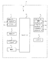
- FIG. 1 is a block diagram illustrating a configuration of a vehicle control system commonly applied to each embodiment of the present invention.
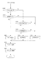
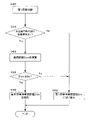
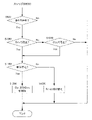
- FIG. 2 is a flowchart illustrating the automatic driving control method according to the first embodiment.
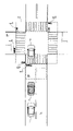
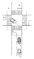
- FIG. 3 is a diagram illustrating an example of a specific scene to which the first stop control is applied.
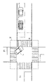
- FIG. 4 is a diagram illustrating an example of a specific scene to which the second stop control is applied.
- FIG. 5 is a flowchart illustrating the automatic driving control method according to the second embodiment.
- FIG. 6 is a flowchart illustrating the automatic driving control method according to the third embodiment.
- FIG. 7 is a flowchart illustrating the first stop control according to the fourth embodiment.
- FIG. 8 is a flowchart illustrating the automatic driving control method according to the fifth embodiment.
- FIG. 1 is a block diagram illustrating a configuration of a vehicle control system commonly applied to each embodiment of the present invention.
- FIG. 2 is a flowchart illustrating the automatic driving control method according to the
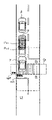
- FIG. 9 is a diagram showing an example of a specific scene in which the priority switching process is assumed to be executed.
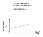
- FIG. 10 is a diagram showing an example of a map that defines the relationship between the number of vehicles in an intersection and the correction target inter-vehicle distance to be set in the automatic driving control method of the sixth embodiment.
- FIG. 11 is a flowchart illustrating the automatic operation control method according to the seventh embodiment.
- FIG. 12A is a diagram illustrating a modification 1.
- FIG. 12B is a diagram illustrating a modification 2.
- FIG. 12C is a diagram illustrating a modified example 3.
- FIG. 12D is a diagram illustrating a modified example 4.
- forward in the present specification means the traveling direction of the vehicle (hereinafter referred to as "own vehicle ⁇ ") to which the automatic driving control method of the embodiment should be executed (the traveling lane L1 of the own vehicle ⁇ ). It means the front in the traveling direction specified by).
- rear means the rear in the traveling direction of the own vehicle ⁇ to which the automatic driving control method of the embodiment should be executed. Therefore, the front or rear with respect to the crossing lane Ct, which will be described later, is not universally determined, and is traveling in the traveling direction of the own vehicle ⁇ (traveling in the traveling lane L1 or traveling in the lane opposite to the traveling lane L1). ) Is determined as appropriate.
- FIG. 1 is a diagram illustrating a configuration of a vehicle control system 10 commonly applied to each embodiment.
- the vehicle control system 10 includes an external sensor 1, an internal sensor 2, a navigation system 3, a communication interface 4, an actuator 5, a display 6, and a controller 20.
- the vehicle control system 10 is mounted on a vehicle (hereinafter referred to as "own vehicle ⁇ ") to which the automatic driving control method of the present embodiment should be executed.
- the external sensor 1 is a detection device that detects the surrounding condition of the own vehicle ⁇ .
- the external sensor 1 includes an in-vehicle camera 1a and a radar 1b.
- the in-vehicle camera 1a is an imaging device that images the periphery of the own vehicle ⁇ .
- the in-vehicle camera 1a is provided, for example, on the vehicle interior side of the windshield of the own vehicle ⁇ .
- the vehicle-mounted camera 1a is composed of a monocular camera or a stereo camera.
- the vehicle-mounted camera 1a outputs the captured peripheral image of the own vehicle ⁇ to the controller 20.
- Radar 1b uses radio waves to detect objects such as other vehicles that exist outside the own vehicle ⁇ .
- the radio wave is, for example, millimeter wave. More specifically, the radar 1b transmits radio waves around the own vehicle ⁇ , receives radio waves reflected by the object, and detects the object.
- the radar 1b can output, for example, the distance or direction to an object as object information (particularly, peripheral vehicle information).
- the radar 1b outputs the detected peripheral vehicle detection data to the controller 20.
- a rider (LIDER: Laser Imaging Detection and Ringing) that detects an external object of the own vehicle ⁇ by using light may be mounted as the external sensor 1.
- the internal sensor 2 is a detector that detects various information according to the traveling state of the own vehicle ⁇ .
- the internal sensor 2 includes a vehicle speed sensor that detects the vehicle speed of the own vehicle ⁇ (hereinafter, also referred to as “own vehicle vehicle speed V ⁇ ”), an acceleration sensor that detects the acceleration of the own vehicle ⁇ , and the like.
- the navigation system 3 is a device that obtains travel route information to a destination set on a map by an occupant such as a driver of the own vehicle ⁇ and outputs the information to the controller 20. More specifically, the navigation system 3 targets the travel route set in the own vehicle ⁇ based on the position information of the own vehicle ⁇ measured by GPS (Global Positioning System) and the map information of the predetermined map database. Obtained as route information. In addition to information on routes that can be traveled, this map information is an HD map (dynamic) that includes information such as the number of lanes or the size of the shoulder, the amount of travel of other vehicles, or the presence or absence of obstacles. Map) may be included.
- GPS Global Positioning System
- the communication interface 4 is composed of various communication protocols for receiving information necessary for traveling of the own vehicle ⁇ and information pointed out by the occupant from a predetermined external server and transmitting the information to the controller 20.
- the communication interface 4 enables, for example, V2V (Vehicle to Vehicle) that enables communication between the controller 20 and another vehicle (vehicle-to-vehicle communication), and communication between the controller 20 and infrastructure equipment such as a traffic light (road-vehicle communication). It is realized by V2I (Vehicle to Infrastructure) and V2N (Vehicle to Network) that enables communication between the controller 20 and a predetermined external server (including the cloud).
- V2V Vehicle to Vehicle
- V2N Vehicle to Network
- the actuator 5 is a device for operating the own vehicle ⁇ in a traveling state in response to a command from the controller 20.
- the actuator 5 includes a drive actuator 5a, a brake actuator 5b, and a steering actuator 5c.
- the drive actuator 5a is a device for adjusting the driving force of the own vehicle ⁇ .
- the drive actuator 5a is composed of a throttle actuator or the like that adjusts the amount of air supplied to the engine (throttle opening degree).
- the drive actuator 5a is composed of a circuit (inverter, converter, etc.) capable of adjusting the power supplied to the motor. Will be done.
- the brake actuator 5b is a device that adjusts the braking force acting on the own vehicle ⁇ .
- the brake actuator 5b is realized by a configuration for obtaining the braking force of the own vehicle ⁇ by frictional force (disc brake, etc.) and / or a configuration for obtaining the regenerative force of a motor mounted as a traveling drive source (regenerative braking). Will be done.
- the steering actuator 5c is composed of an assist motor or the like that controls the steering torque in the electric power steering system.
- the display 6 is a device arranged in the vehicle interior and displaying information based on the calculation result executed by the controller 20.
- the display 6 may be incorporated in a device equipped with an HMI (Human Machine Interface) that receives input (touch panel operation, etc.) from the occupant of the own vehicle ⁇ .
- HMI Human Machine Interface
- the controller 20 as an automatic operation control device is composed of a computer equipped with a central processing unit (CPU), a read-only memory (ROM), a random access memory (RAM), and an input / output interface (I / O interface).
- the controller 20 is programmed so that each process in the automatic operation control method described later can be executed.
- the function of the controller 20 is realized by an ADAS (Advanced Driver Assistance Systems) / AD (Autonomous Driving) controller that performs main processing related to the operation control of the own vehicle ⁇ .
- the function of the controller 20 may be realized by an arbitrary computer mounted on the own vehicle ⁇ such as a motor controller, an ECU (Engine Control Unit), or a vehicle control unit (VCU: Vehicle Control Unit). good.
- the controller 20 may be configured by mounting a program on one computer hardware, or by mounting a program in which each process is distributed on a plurality of computer hardware, the plurality of computer hardware may be mounted. The hardware may be integrated to execute the automatic operation control method of each embodiment.
- the controller 20 performs various calculations for executing the automatic driving control method of each embodiment by inputting various information received from the external sensor 1, the internal sensor 2, the navigation system 3, and the communication interface 4, and the calculation result. Is displayed on the display 6, and the actuator 5 is operated based on the calculation result.
- the controller 20 operates the actuator 5 to operate the actuator 5 to adjust the inter-vehicle distance between the own vehicle ⁇ and the preceding vehicle ⁇ to a predetermined target inter-vehicle distance, and the vehicle speed V ⁇ of the own vehicle and the vehicle speed of the preceding vehicle ⁇ (hereinafter referred to as follows). , Also referred to as "preceding vehicle vehicle speed V ⁇ ").
- the target inter-vehicle distance is set to a predetermined appropriate inter-vehicle distance from the viewpoint of safety and suppression of interruption of other vehicles.
- the target inter-vehicle distance may be a fixed value or a variable value that fluctuates according to the traveling state of the own vehicle ⁇ (own vehicle vehicle speed V ⁇ , acceleration, etc.).
- the target vehicle-to-vehicle distance at the timing when the own vehicle ⁇ stops following the stop of the preceding vehicle ⁇ (the timing when both the own vehicle speed V ⁇ and the preceding vehicle vehicle speed V ⁇ become 0) is referred to as “the inter-vehicle distance when stopped”. It is called "D ⁇ ".
- the inter-vehicle distance D ⁇ when the vehicle is stopped is set as an appropriate value from the viewpoint of maintaining an appropriate inter-vehicle distance with respect to the preceding vehicle ⁇ in the stopped state of the own vehicle ⁇ .
- “basic stop-to-vehicle distance D ⁇ 0 ", "first stop-to-vehicle distance D ⁇ 1 ", and “second stop-to-vehicle distance D ⁇ 1" are used as appropriate stop-to-vehicle distances D ⁇ according to various scenes. Set to one of the inter-vehicle distance D ⁇ 2 ”.
- the basic inter-vehicle distance D ⁇ 0 when the vehicle is stopped is set to an appropriate value (for example, about 5 m) from the viewpoint that the preceding vehicle ⁇ can be avoided by turning when the own vehicle ⁇ starts traveling from the stopped state.
- an appropriate value for example, about 5 m
- the basic inter-vehicle distance D ⁇ 0 can be set to a value further larger than the value that can be avoided by turning the preceding vehicle ⁇ described above. ..
- FIG. 2 is a flowchart illustrating the automatic operation control method of the present embodiment.
- the controller 20 repeatedly executes the process described below at predetermined control cycles. Further, in the present embodiment,
- the controller 20 acquires various input information.
- the controller 20 includes information detected by the external sensor 1 (particularly, the distance between the own vehicle ⁇ and the preceding vehicle ⁇ , the preceding vehicle vehicle speed V ⁇ , and the like), and information detected by the internal sensor 2 (particularly). , Peripheral image, peripheral vehicle detection data, own vehicle speed V ⁇ , etc.), information obtained by the navigation system 3 (including, in particular, position information of own vehicle ⁇ , travel route information, HDD map, etc.), and communication.
- Information obtained by the interface 4 is acquired as input information.
- step S101 the controller 20 causes the own vehicle ⁇ to follow the stop of the preceding vehicle ⁇ and stops the own vehicle ⁇ at the stop position P ⁇ (hereinafter, also referred to as “basic stop position P ⁇ 0 ”) based on the inter-vehicle distance D ⁇ 0 at the time of basic stop. ..
- step S200 the controller 20 determines whether or not the stop position P ⁇ of the own vehicle ⁇ is included in the front stop restriction region Rf set in front of the crossing traffic zone Ct.
- the crossing lane Ct in the present specification is a traveling lane (including an automobile, a tram, and a railroad vehicle) of a traveling lane L1 in which the own vehicle ⁇ travels and a vehicle intersecting the traveling lane L1.
- it means a region defined as a confluence portion of (also referred to as “crossing lane L2”).
- the crossing lane Ct also includes a pedestrian crossing along the traveling lane L1 and a pedestrian crossing along the crossing lane L2.
- the front stop restriction region R f is a region extending over a predetermined range to the outside of the front in the traveling lane L1 of the own vehicle ⁇ with respect to the crossing traffic zone Ct.
- the front stop restriction region R f is a range in which if the stop position P ⁇ of the own vehicle ⁇ is included in the front stop restriction region R f , the following vehicle ⁇ is considered to hinder the forward departure from the crossing lane Ct. Is set to.
- the front stop restriction area R f is stored in advance in a storage area that can be read by the controller 20. Considering that the length from the stop position P ⁇ of the own vehicle ⁇ to the rear end of the vehicle body differs depending on the vehicle type, etc., the extended length of the front stop restriction region R f is set to the vehicle body size of the own vehicle ⁇ (particularly in detail). It may be adjusted as appropriate according to the vehicle length and width).
- the controller 20 determines whether or not the stop position P ⁇ is included in the front stop restriction region Rf based on the peripheral image, the peripheral vehicle detection data, and the previously known vehicle body size of the own vehicle ⁇ . Execute with reference to data and / or HD map. Then, when the controller 20 determines that the stop position P ⁇ is included in the forward stop restriction region Rf , the controller 20 executes the first stop control in step S400.
- step S400 the controller 20 switches the inter-vehicle distance D ⁇ at the time of stop to the first inter-vehicle distance D ⁇ 1 at the time of stop, which is shorter than the basic inter-vehicle distance D ⁇ 0 at the time of stop.
- the first stop inter-vehicle distance D ⁇ 1 changes the stop position P ⁇ to the front (direction in which the distance from the preceding vehicle ⁇ is narrowed) so that the stop position P ⁇ is not included in the front stop restriction region Rf .
- it is a correction value determined to reduce and correct the inter-vehicle distance D ⁇ 0 when the vehicle is basically stopped.
- the distance D ⁇ 1 at the time of the first stop is such that the distance between the preceding vehicle ⁇ and the own vehicle ⁇ is not excessively narrowed while realizing the purpose that the stop position P ⁇ is not included in the front stop restriction region Rf . It is preferable to set the length (for example, about 1/2 of the basic inter-vehicle distance D ⁇ 0 ). Then, when the controller 20 switches the stopped inter-vehicle distance D ⁇ to the first stopped inter-vehicle distance D ⁇ 1 , the process after step S700 is executed.
- step S300 determines in step S200 that the stop position P ⁇ is not included in the front stop restriction region Rf .
- the controller 20 determines whether or not the stop position P ⁇ is included in the rear stop restriction region Rr.
- the rear stop restriction region Rr is an region extending over a predetermined range to the outside of the rear in the traveling lane L1 of the own vehicle ⁇ with respect to the crossing traffic zone Ct.
- the rear stop restriction region Rr is set in a range in which if the stop position P ⁇ is included in the rear stop restriction region Rr , the retreat departure from the crossing lane Ct by the preceding vehicle ⁇ is considered to be hindered. ..
- the rear stop restriction area Rr is stored in advance in a storage area that can be read by the controller 20.
- the extended length of the rear stop restriction area R r may be appropriately adjusted according to the vehicle body size of the own vehicle ⁇ (particularly, the vehicle length and the vehicle width). ..
- the controller 20 determines whether or not the stop position P ⁇ is included in the rear stop restriction region Rr, based on the peripheral image, the peripheral vehicle detection data, and the previously known vehicle body size of the own vehicle ⁇ . Execute with reference to data and / or HD map. Then, when the controller 20 determines that the stop position P ⁇ is included in the rear stop restriction region Rr, the controller 20 executes the second stop control in step S500.
- step S500 the controller 20 switches the inter-vehicle distance D ⁇ at the time of stop to the second inter-vehicle distance D ⁇ 2 at the time of stop, which is longer than the basic inter-vehicle distance D ⁇ 0 at the time of stop.
- the second stop-time inter-vehicle distance D ⁇ 2 changes the stop position P ⁇ to the rear (direction in which the distance from the preceding vehicle ⁇ increases) so that the stop position P ⁇ is not included in the rear stop restriction region Rr. From the viewpoint, it is a correction value defined to increase and correct the inter-vehicle distance D ⁇ 0 when the vehicle is basically stopped.
- the second stop distance D ⁇ 2 is such that the distance between the own vehicle ⁇ and the following vehicle ⁇ is not excessively narrowed while realizing the purpose of preventing the stop position P ⁇ from being included in the rear stop restriction region Rr. It is preferable to set the length. Then, when the controller 20 switches the stopped inter-vehicle distance D ⁇ to the second stopped inter-vehicle distance D ⁇ 2 , the process after step S700 is executed.
- step S300 determines in step S300 that the stop position P ⁇ is not included in the rear stop restriction region Rr, the controller 20 executes the process of step S600.
- step S600 the controller 20 maintains the inter-vehicle distance D ⁇ at the time of stop at the basic inter-vehicle distance D ⁇ 0 at the time of basic stop (maintains the stop position P ⁇ at the basic stop position P ⁇ 0 ), and processes after step S700. To execute.
- step S400 when the controller 20 completes any of the processes related to the first stop control (step S400), the second stop control (step S500), and the basic stop control (step S600) described above, the controller 20 performs the process of step S700. Run.
- step S700 the controller 20 performs a process of displaying on the display 6 information to be notified to the occupant of the own vehicle ⁇ in response to the execution of either the first stop control or the second stop control.
- the controller 20 has a text to the effect that "the vehicle behind cannot leave, so the distance between the vehicle and the vehicle in front is narrowed" and, if necessary, the occupant's understanding of the text.
- the image information that assists is displayed on the display 6.
- the controller 20 has a text to the effect that "the vehicle in front cannot leave, so there is a space between vehicles” and, if necessary, image information that assists the occupants in understanding the text. Is displayed on the display 6.
- the specific contents displayed on the display 6 are not limited to these, and can be changed as appropriate.
- step S800 the controller 20 determines the actual inter-vehicle distance between the preceding vehicle ⁇ and the own vehicle ⁇ by the first stop control, the second stop control, or the basic stop control (that is, at the time of the first stop).
- the actuator 5 is operated so as to approach the vehicle-to-vehicle distance D ⁇ 1 , the second vehicle-to-vehicle distance D ⁇ 2 , or the basic vehicle-to-vehicle distance D ⁇ 0 ).
- step S400 the controller 20 sets the stop position P ⁇ of the own vehicle ⁇ to a position ahead of the basic stop position P ⁇ 0 (hereinafter, also referred to as “first correction stop position P ⁇ 1 ”). Move the own vehicle ⁇ so as to change to).
- step S500 the controller 20 sets the stop position P ⁇ of the own vehicle ⁇ to a position behind the basic stop position P ⁇ 0 (hereinafter, also referred to as “second correction stop position P ⁇ 2 ”). Move the own vehicle ⁇ so as to change to).
- step S600 the controller 20 maintains the stop position P ⁇ at the basic stop position P ⁇ 0 .
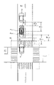
- FIG. 3 is a diagram illustrating an example of a specific scene to which the first stop control is applied.
- FIG. 3 assumes a scene in which the basic stop position P ⁇ 0 of the own vehicle ⁇ is included in the forward stop restriction region Rf (see the own vehicle ⁇ represented by the alternate long and short dash line).
- the inter-vehicle distance D ⁇ at the time of stopping is shorter than the basic inter-vehicle distance D ⁇ 0 at the time of stopping according to the control logic of steps S200 and S400. It will be set to D ⁇ 1 .
- the own vehicle ⁇ moves so that the stop position P ⁇ is changed from the basic stop position P ⁇ 0 to the first correction stop position P ⁇ 1 in front, the own vehicle ⁇ (more specifically, the vehicle body of the own vehicle ⁇ ) The space between the rear end) and the crossing lane Ct can be widened to allow the following vehicle ⁇ to move forward.
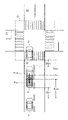
- FIG. 4 is a diagram illustrating an example of a specific scene to which the second stop control is applied.
- FIG. 4 assumes a scene in which the basic stop position P ⁇ 0 of the own vehicle ⁇ is included in the rear stop restriction region Rr (see the own vehicle ⁇ represented by the alternate long and short dash line).
- the inter-vehicle distance D ⁇ at the time of stopping is longer than the basic inter-vehicle distance D ⁇ 0 at the time of stopping according to the control logic of steps S200 and S500.
- D ⁇ 2 will be set.
- the own vehicle ⁇ moves so that the stop position P ⁇ is changed from the basic stop position P ⁇ 0 to the second correction stop position P ⁇ 2 behind, the crossing lane Ct and the own vehicle ⁇ (more specifically, the own vehicle ⁇ )
- the space between the front end of the vehicle body of the vehicle ⁇ ) can be widened to allow the preceding vehicle ⁇ to retreat.
- an automatic driving control method for stopping the own vehicle ⁇ so that the inter-vehicle distance with respect to the preceding vehicle ⁇ becomes a predetermined inter-vehicle distance D ⁇ at the time of stopping is provided.
- the inter-vehicle distance D ⁇ at the time of stop is predetermined.
- the first stop control (step S400) for setting the first stop distance D ⁇ 1 shorter than the basic stop distance D ⁇ 0 is executed.
- the stop position P ⁇ of the own vehicle ⁇ is included in the rear stop restriction area Rr set behind the crossing traffic zone Ct (Yes in step S300)
- the inter-vehicle distance D ⁇ at the time of stop is set as the basic inter-vehicle distance at the time of stop.
- the second stop control (step S600) for setting the inter-vehicle distance D ⁇ 2 at the time of the second stop, which is longer than the distance D ⁇ 0 is executed.
- the stop position P ⁇ of the own vehicle ⁇ (particularly, the basic stop position P ⁇ 0 ) is included in the front stop restriction region Rf , the own vehicle ⁇ is placed ahead of the original stop position P ⁇ (first position). It can be changed to the corrected stop position P ⁇ 1 ). Therefore, it is possible to increase the space between the own vehicle ⁇ in the stopped state and the crossing lane Ct located behind the own vehicle ⁇ . That is, since the space for the following vehicle ⁇ to move forward from the crossing lane Ct and evacuate can be secured, it is possible to prevent the following vehicle ⁇ from being left behind in the crossing lane Ct.
- the own vehicle ⁇ can be changed to a position behind the original stop position P ⁇ (second corrected stop position P ⁇ 2 ). .. Therefore, it is possible to increase the space between the own vehicle ⁇ in the stopped state and the crossing lane Ct located in front of the own vehicle ⁇ . That is, since the space for the preceding vehicle ⁇ to retreat from the crossing lane Ct and evacuate can be secured, it is possible to prevent the preceding vehicle ⁇ from being left behind in the crossing lane Ct.
- the traveling of the vehicle in the crossing lane Ct (for example, the vehicle in the crossing lane L2) is hindered. It is possible to improve the traffic efficiency by suppressing the situation.
- the own vehicle ⁇ advances from the crossing lane Ct of the following vehicle ⁇ .
- the rear stop restriction area Rr is set to a range that hinders the reverse departure of the preceding vehicle ⁇ from the crossing lane Ct when the stop position P ⁇ of the own vehicle ⁇ is included in the rear stop restriction area Rr .
- the vehicle-to-vehicle distance D ⁇ when stopped is set to the basic inter-vehicle distance D ⁇ 0 when stopped, and the own vehicle ⁇ is stopped (step S101). Then, whether the stop position P ⁇ of the own vehicle ⁇ is included in the front stop restriction area R f , is included in the rear stop restriction area R r , or is either the front stop restriction area R f or the rear stop restriction area R r . It is determined whether or not it is included in (step S200 and step S300). Then, when it is determined that the stop position P ⁇ of the own vehicle ⁇ is included in the forward stop restriction region Rf , the first stop control is executed (Yes in step S200 and step S400).
- step S300 and step S500 the second stop control is executed (Yes in step S300 and step S500). Further, if it is determined that the stop position P ⁇ of the own vehicle ⁇ is not included in either the front stop restriction area R f or the rear stop restriction area R r , the basic stop control for maintaining the basic stop distance D ⁇ 0 is executed. (No in step S200, No in step S300, and step S600).
- the present embodiment is an automatic driving control device for executing the above-mentioned automatic driving control method, and the own vehicle ⁇ is stopped so that the inter-vehicle distance with respect to the preceding vehicle ⁇ becomes a predetermined inter-vehicle distance D ⁇ at the time of stopping.
- the controller 20 as an automatic operation control device is provided.
- the controller 20 has at least one of a first stop control unit (step S400) and a second stop control unit (step S500). Then, when the stop position P ⁇ of the own vehicle ⁇ is included in the front stop restriction region Rf set in front of the crossing traffic zone Ct (Yes in step S200), the first stop control unit is the inter-vehicle distance D ⁇ at the time of stop. Is set to the first inter-vehicle distance D ⁇ 1 when the vehicle is stopped, which is shorter than the predetermined basic inter-vehicle distance D ⁇ 0 . Further, when the stop position P ⁇ of the own vehicle ⁇ is included in the rear stop restriction area Rr set behind the crossing traffic zone Ct (Yes in step S300), the second stop control unit is between vehicles at the time of stop. The distance D ⁇ is set to the second vehicle-to-vehicle distance D ⁇ 2 , which is longer than the basic stop-to-vehicle distance D ⁇ 0 .
- the stop position P ⁇ of the own vehicle ⁇ is predicted in advance, and the predicted stop position P ⁇ (hereinafter, also referred to as “scheduled stop position P ⁇ ⁇ ”) is the front stop restriction area R f or the rear stop restriction area R r.
- Scheduled stop position P ⁇ ⁇ is the front stop restriction area R f or the rear stop restriction area R r.
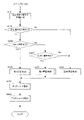
- FIG. 5 is a flowchart illustrating the automatic operation control method of the present embodiment.
- the controller 20 repeatedly executes the process described below at predetermined control cycles.
- step S100 the controller 20 acquires various input information as in the first embodiment.
- step S110 the controller 20 determines whether or not the own vehicle ⁇ is scheduled to stop. Specifically, the controller 20 refers to the peripheral image and / or the peripheral vehicle detection data, etc., based on whether or not the preceding vehicle vehicle speed V ⁇ related to the preceding vehicle ⁇ to be followed is equal to or less than a predetermined value. , It is determined whether or not the own vehicle ⁇ is in the state of the process leading to the stop (immediately before the stop).
- step S115 the controller 20 calculates the planned stop position P ⁇ ⁇ . Specifically, the controller 20 assumes that the inter-vehicle distance D ⁇ when stopped is set to the basic inter-vehicle distance D ⁇ 0 when the vehicle is stopped, and when the vehicle speed V ⁇ of the own vehicle, the vehicle speed V ⁇ of the preceding vehicle, and the vehicle speed difference ⁇ V ⁇ all reach 0. The position where the own vehicle ⁇ is predicted to stop is obtained as the planned stop position P ⁇ ⁇ .
- the planned stop position P ⁇ ⁇ when the inter-vehicle distance D ⁇ when the vehicle is stopped is set to the basic inter-vehicle distance D ⁇ 0 when the vehicle is stopped is also referred to as “basic stop scheduled position P ⁇ ⁇ 0 ”.
- step S120 the controller 20 determines whether or not the crossing lane Ct exists around the basic stop schedule position P ⁇ ⁇ 0 . Specifically, the controller 20 crosses the lane Ct around the basic stop schedule position P ⁇ ⁇ 0 based on the peripheral image, the traveling route information, the HD map, the vehicle-to-vehicle communication information, and / or the road-to-vehicle communication information. Determines if is present.
- step S600 the controller 20 maintains a state in which the inter-vehicle distance D ⁇ when stopped is set to 0 as the basic inter-vehicle distance D ⁇ when stopped.
- the controller 20 determines that the crossing traffic zone Ct exists around the basic stop scheduled position P ⁇ ⁇ 0 , the controller 20 executes the processing after step S200'.
- step S200' the controller 20 determines whether or not the basic stop schedule position P ⁇ ⁇ 0 is included in the front stop restriction region R f of the crossing traffic zone Ct. Specifically, the controller 20 makes the determination with reference to peripheral images, travel route information, and / or HD maps, etc., and coordinates in a predetermined coordinate system (for example, world coordinates) of the basic stop scheduled position P ⁇ ⁇ 0 . Is included in the range that defines the front stop restriction area R f on the same coordinate system.
- a predetermined coordinate system for example, world coordinates
- step S400 the controller 20 switches the inter-vehicle distance D ⁇ when stopped from the basic inter-vehicle distance D ⁇ 0 when stopped to the shorter first inter-vehicle distance D ⁇ 1 when stopped.
- the controller 20 determines that the basic stop scheduled position P ⁇ ⁇ 0 is not included in the front stop restriction area R f , the controller 20 executes the process of step S300'.
- step S300' the controller 20 determines whether or not the basic stop schedule position P ⁇ ⁇ 0 is included in the rear stop restriction region Rr of the crossing traffic zone Ct. Specifically, the controller 20 makes the determination with reference to peripheral images, travel route information, and / or HD maps, etc., and coordinates in a predetermined coordinate system (for example, world coordinates) of the basic stop scheduled position P ⁇ ⁇ 0 . Is included in the range that defines the rear stop restriction area Rr on the same coordinate system.
- a predetermined coordinate system for example, world coordinates
- step S500 the controller 20 determines that the basic stop scheduled position P ⁇ ⁇ 0 is included in the rear stop restriction region Rr . That is, as in the first embodiment, the controller 20 switches the inter-vehicle distance D ⁇ when stopped from the basic inter-vehicle distance D ⁇ 0 when stopped to the second inter-vehicle distance D ⁇ 2 when stopped, which is longer than this.
- step S600 basic stop control
- the stop position P ⁇ (scheduled stop position P ⁇ ⁇ ) when the own vehicle ⁇ is stopped by setting the inter-vehicle distance D ⁇ at the time of stop to the basic inter-vehicle distance D ⁇ 0 at the time of stop is predicted ( Step S115). Further, it is determined whether or not the predicted stop schedule position P ⁇ ⁇ (particularly the basic stop schedule position P ⁇ ⁇ 0 ) is included in the front stop restriction area R f or the rear stop restriction area R r (step S200'and Step S300').
- step S200'and step S400 the first stop control is executed (Yes in step S200'and step S400).
- the second stop control is executed (Yes in step S300'and step S500).
- the basic stop control for maintaining the basic stop distance D ⁇ 0 is executed. (No in step S200', No in step S300', and step S600).
- the stop position P ⁇ when the vehicle actually stops is included in the front stop restriction area R f or the rear stop restriction area R r (that is, the following vehicle ⁇ or the preceding vehicle ⁇ .
- a specific control logic for appropriately adjusting the inter-vehicle distance D ⁇ when the vehicle is stopped is realized by predicting in advance the situation that hinders the evacuation from the crossing traffic zone Ct. Therefore, since the own vehicle ⁇ can be directly stopped so as not to hinder the evacuation of the following vehicle ⁇ or the preceding vehicle ⁇ from the crossing lane Ct, the control of temporarily stopping the own vehicle ⁇ and then moving it again is omitted. be able to. As a result, while preventing the situation in which the following vehicle ⁇ or the preceding vehicle ⁇ is left behind in the crossing lane Ct, it is possible to reduce the discomfort of the occupant caused by moving the own vehicle ⁇ again after stopping.
- FIG. 6 is a flowchart illustrating the automatic operation control method of the present embodiment.
- the blocks of step S100, step S115, and step S120, which are common to FIG. 5, are not shown.
- step S200 when the controller 20 determines in step S200'that the basic stop scheduled position P ⁇ ⁇ 0 is included in the front stop restriction region Rf of the crossing traffic zone Ct, the controller 20 executes the process of step S210.
- step S210 the controller 20 determines whether or not the following vehicle ⁇ exists in the crossing traffic zone Ct. Specifically, the controller 20 refers to a peripheral image (particularly an image of the rear of the own vehicle ⁇ ), peripheral vehicle detection data, and / or vehicle-to-vehicle communication information, and the following vehicle ⁇ in the crossing lane Ct. Determines if is present.
- step S400 determines that the controller 20 determines that the following vehicle ⁇ exists in the crossing traffic zone Ct
- step S600 basic stop control
- the controller 20 determines that the basic stop schedule position P ⁇ ⁇ 0 is not included in the forward stop restriction area Rf in the above step S200', and then in the subsequent step S300', the basic stop schedule position P ⁇ ⁇ 0 . Is included in the rear stop restriction area Rr , the process of step S310 is executed.
- step S310 the controller 20 determines whether or not the preceding vehicle ⁇ exists in the crossing traffic zone Ct. Specifically, the controller 20 refers to a peripheral image (particularly an image of the front of the own vehicle ⁇ ), peripheral vehicle detection data, and / or vehicle-to-vehicle communication information, and the preceding vehicle ⁇ in the crossing lane Ct. Determines if is present.
- step S500 when the controller 20 determines that the preceding vehicle ⁇ exists in the crossing lane Ct, the controller 20 executes the second stop control in step S500.
- the controller 20 determines that the preceding vehicle ⁇ does not exist in the crossing traffic zone Ct, the controller 20 executes the basic stop control in step S600.
- the stop position P ⁇ (basic stop schedule position P ⁇ ⁇ 0 ) of the own vehicle ⁇ is included in the front stop restriction region Rf , the following vehicle ⁇ is further within the crossing traffic zone Ct. Is determined (Yes in step S200'and step S210). Then, if it is determined that the following vehicle ⁇ exists, the first stop control is executed (Yes in step S210 and step S400), and if it is determined that the following vehicle ⁇ does not exist, the inter-vehicle distance D ⁇ at the time of stopping is used as the basic inter-vehicle distance D ⁇ at the time of stopping. It is maintained at 0 (No in step S210 and step S600).
- step S300 ′ it is further determined whether or not the preceding vehicle ⁇ exists in the crossing traffic zone Ct (step S300 ′). Yes and step S310). Then, when it is determined that the preceding vehicle ⁇ exists, the second stop control is executed (Yes in step S310 and step S500), and when it is determined that the preceding vehicle ⁇ does not exist, the inter-vehicle distance D ⁇ at the time of stopping is used as the basic inter-vehicle distance D ⁇ at the time of stopping. It is maintained at 0 (No in step S310 and step S600).
- the stop position P ⁇ of the own vehicle ⁇ is included in the front stop restriction area R f or the rear stop restriction area R r , the following vehicle ⁇ or the preceding vehicle ⁇ which may be further left behind in the crossing lane Ct.
- a specific control logic for adjusting the inter-vehicle distance D ⁇ when the vehicle is stopped is realized. Therefore, the control for changing the stop position P ⁇ of the own vehicle ⁇ from the basic stop position P ⁇ 0 to the first corrected stop position P ⁇ 1 in the front or the second corrected stop position P ⁇ 2 in the rear is changed to the following vehicle ⁇ or the preceding vehicle ⁇ .
- step S400 one aspect of the specific processing in the first stop control (step S400) will be described.
- the first stop control of the present embodiment when the inter-vehicle distance D ⁇ at the time of stop is not immediately switched from the basic inter-vehicle distance D ⁇ 0 at the time of stop to the inter-vehicle distance D ⁇ 1 at the first stop, a certain condition is satisfied. Perform the switch.
- FIG. 7 is a flowchart illustrating the first stop control of the present embodiment.
- step S410 the controller 20 determines whether or not the following vehicle ⁇ exists in a predetermined distance range in front of the crossing lane Ct.
- this distance range the following vehicle ⁇ is placed in the crossing lane Ct to the extent that there is a realistic possibility that the following vehicle ⁇ is blocked by the own vehicle ⁇ in the stopped state and left in the crossing lane Ct. It is set within an appropriate range from the viewpoint of judging whether or not it is approaching.
- the controller 20 refers to a peripheral image (particularly an image of the rear of the own vehicle ⁇ ), peripheral vehicle detection data, and / or vehicle-to-vehicle communication information, and the following vehicle ⁇ exists in the above distance range. Determine whether or not to do so.
- step S450 the controller 20 proceeds to step S450 and the inter-vehicle distance when the vehicle is stopped.
- the D ⁇ is switched from the basic stop distance D ⁇ 0 to the first stop distance D ⁇ 1 .
- the controller 20 executes the process of step S420.
- step S420 the controller 20 obtains the separation distance D ⁇ Ct (see FIG. 3) from the own vehicle ⁇ to the rear crossing lane Ct with reference to the image of the vehicle-mounted camera 1a and / or the peripheral vehicle detection data. ..
- step S430 the controller 20 determines whether or not the separation distance D ⁇ Ct is equal to or less than the predetermined threshold distance Dth .
- the threshold distance D th is an appropriate value as a criterion for determining whether the magnitude of the separation distance D ⁇ Ct allows the following vehicle ⁇ to enter the space between the own vehicle ⁇ and the crossing lane Ct. It is stipulated in.
- step S440 the process proceeds to step S440, and the vehicle-to-vehicle distance D ⁇ when stopped is maintained at the basic inter-vehicle distance D ⁇ 0 when stopped.
- the process proceeds to step S450, and the inter-vehicle distance D ⁇ when the vehicle is stopped is basically used.
- the inter-vehicle distance D ⁇ 0 when the vehicle is stopped is switched to the inter-vehicle distance D ⁇ 1 when the first vehicle is stopped.
- step S410 it is determined whether or not the following vehicle ⁇ exists in a predetermined distance range in front of the crossing traffic zone Ct. Then, when it is determined that the following vehicle ⁇ exists in the distance range, it is determined whether or not the separation distance D ⁇ Ct from the own vehicle ⁇ to the rear crossing lane Ct exceeds a predetermined threshold distance Dth (step S420 and step). S430).
- the inter-vehicle distance D ⁇ at the time of stopping is switched from the basic inter-vehicle distance D ⁇ 0 at the time of stopping to the inter-vehicle distance D ⁇ 1 at the first stop (No in step S430 and step S450). .. Further, if it is determined that the separation distance D ⁇ Ct does not exceed the threshold distance Dth, the inter-vehicle distance D ⁇ at the time of stopping is maintained at the basic inter-vehicle distance D ⁇ 0 at the time of stopping (Yes in step S430 and step S440).
- the own vehicle ⁇ when the space between the own vehicle ⁇ and the crossing lane Ct is not sufficiently wide from the viewpoint of allowing the following vehicle ⁇ to enter (when the separation distance D ⁇ Ct ⁇ threshold distance Dth), the own vehicle ⁇ The stop position P ⁇ of is maintained at the basic stop position P ⁇ 0 . Therefore, even though the space between the own vehicle ⁇ and the crossing lane Ct is not wide enough, the own vehicle ⁇ stops slightly at the first correction stop position P ⁇ 1 ahead of the basic stop position P ⁇ 0 . It is possible to prevent the following vehicle ⁇ from forcibly entering the expanded space.
- FIG. 8 is a flowchart illustrating the automatic operation control method of the present embodiment.
- the blocks of step S100, step S115, and step S120, which are common to FIG. 5, are not shown.
- the controller 20 executes the priority switching process for predicting the priority switching in the traveling of the crossing lane Ct in step S121.
- the controller 20 uses peripheral images, vehicle-to-vehicle communication information, and / or road-to-vehicle communication information as input information, and gives priority to traveling of the preceding vehicle ⁇ , the own vehicle ⁇ , and the following vehicle ⁇ in the traveling lane L1. Predicts whether to switch to the crossing lane L2 (in particular, whether the driving priority in the traveling lane L1 is lost).
- the controller 20 predicts the time until the signal display in the traveling lane L1 of the own vehicle ⁇ switches from the traffic permission display (green light) to the traffic prohibition display (red light) (hereinafter, “priority switching predicted time”). ”) Is calculated.
- FIG. 9 is a diagram showing an example of a specific scene in which the priority switching process is expected to be executed.
- the controller 20 displays, from the above input information, the traffic signal sv1 for displaying the progress permission / non-permission in the traveling lane L1 of the own vehicle ⁇ and the progress permission / disapproval in the crossing traveling lane L2.
- Traffic light sv2 for vehicles pedestrian traffic light sp1 for displaying permission / non-permission at the pedestrian crossing along the traveling lane L1, and permission / disapproval of progress at the pedestrian crossing along the crossing lane L2
- Each display of the pedestrian traffic light sp2 (red, yellow, and blue lighting / blinking state, etc.) and / or the switching pattern of each of these displays is obtained, and the priority switching predicted time is calculated.
- step S122 the controller 20 determines whether or not the priority is switched. Specifically, the controller 20 determines that the priority is switched when the priority switching predicted time calculated in step S122 is equal to or less than the predetermined threshold time, and the priority switching predicted time exceeds the threshold time. It is judged that the priority is not switched to. In this threshold time, when the basic stop scheduled position P ⁇ ⁇ 0 of the own vehicle ⁇ is included in the front stop restriction area R f or the rear stop restriction area R r , the preceding vehicle ⁇ or the following vehicle ⁇ is in the crossing lane.
- the timing at which the priority of driving in the traveling lane L1 in the traveling lane L1 (that is, the traveling lane L1 of the preceding vehicle ⁇ and the following vehicle ⁇ ) is approached to the extent that a realistic possibility of being left behind in Ct is assumed. It is set at an appropriate time from the viewpoint of judging whether or not it is done.
- step S200' the process after step S200'is executed in the same manner as in the second embodiment, and the inter-vehicle distance D ⁇ when stopped is set to the inter-vehicle distance D ⁇ 1 when stopped or the second stop. Switch to the hour-to-vehicle distance D ⁇ 2 .
- the controller 20 determines that the priority is not switched, the controller 20 executes the basic stop control. That is, in this case, it is determined that the situation where the preceding vehicle ⁇ or the following vehicle ⁇ is not left behind in the crossing lane Ct does not occur, and the inter-vehicle distance D ⁇ when stopped is maintained at the basic inter-vehicle distance D ⁇ 0 when stopped.
- step S122 it is determined whether or not the priority of the detected crossing lane Ct is switched (step S122), and if it is determined that the priority is not switched, the inter-vehicle distance D ⁇ at the time of stopping is set as the basic stop.
- the inter-vehicle distance D ⁇ is maintained at 0 (No in step S122 and step S600).
- the control for changing the stop position P ⁇ of the own vehicle ⁇ to the first correction stop position P ⁇ 1 in front of the basic stop position P ⁇ 0 or the second correction stop position P ⁇ 2 behind the basic stop position P ⁇ 0 is controlled by the following vehicle ⁇ or the preceding vehicle ⁇ .
- each display red, yellow, and blue lighting / blinking state, etc.
- the pedestrian signal sp1, and / or the pedestrian signal sp2 in the present embodiment.
- the pedestrian signal sp1 and / or the pedestrian signal sp2 in the present embodiment.
- a configuration for calculation may be adopted.
- the controller 20 determines the magnitude of the first stop inter-vehicle distance D ⁇ 1 , the second stop inter-vehicle distance D ⁇ 2 , or both of them based on the number of vehicles existing in the crossing lane Ct. stipulate.
- the controller 20 calculates the number of vehicles existing in the crossing lane Ct based on the peripheral image, the vehicle-to-vehicle communication information, and / or the road-to-vehicle communication information during the first stop control. ..
- the vehicle in the crossing lane Ct to be detected includes a vehicle other than the preceding vehicle ⁇ or the following vehicle ⁇ (another vehicle further preceding the preceding vehicle ⁇ or the following vehicle ⁇ ). In addition, other vehicles that follow) are included.
- the controller 20 determines the first inter-vehicle distance D ⁇ 1 at the time of stopping according to the number of vehicles calculated by referring to the predetermined map.
- the controller 20 determines the second stop inter-vehicle distance D ⁇ 2 according to the number of vehicles existing in the crossing lane Ct during the second stop control.
- FIG. 10 is a diagram showing an example of a map that defines the relationship between the number of vehicles existing in the crossing lane Ct and the first stop inter-vehicle distance D ⁇ 1 (second stop inter-vehicle distance D ⁇ 2 ) to be set. be.
- the first stop inter-vehicle distance D ⁇ 1 (second stop inter-vehicle distance D ⁇ 2 ) becomes the basic stop inter-vehicle distance D ⁇ . It is set longer than 0 .
- At least one of the first stop inter-vehicle distance D ⁇ 1 and the second stop inter-vehicle distance D ⁇ 2 is determined based on the number of vehicles existing in the crossing lane Ct. ..
- the amount of changing the stop position P ⁇ of the own vehicle ⁇ from the basic stop position P ⁇ 0 can be determined according to the number of other vehicles that may actually be left behind in the crossing lane Ct. This prevents the preceding vehicle ⁇ or the following vehicle ⁇ from being left behind in the crossing lane Ct, and appropriately reduces the deviation width of the actual stop position P ⁇ with respect to the originally intended basic stop position P ⁇ 0 according to the situation. Can be made to.
- the magnitudes of the first stop inter-vehicle distance D ⁇ 1 and the second stop inter-vehicle distance D ⁇ 2 are set to be the same. Shows. However, not limited to this, depending on the situation, the magnitudes of the first stop inter-vehicle distance D ⁇ 1 and the second stop inter-vehicle distance D ⁇ 2 with respect to the number of vehicles existing in the crossing lane Ct are different from each other. The embodiment may be adopted.
- the seventh embodiment will be described.
- the same elements as in any of the first to sixth embodiments are designated by the same reference numerals, and the description thereof will be omitted.
- the inter-vehicle distance D ⁇ at the time of stopping is set to the inter-vehicle distance D ⁇ 1 at the time of the first stop or the inter-vehicle distance D ⁇ 2 at the time of the second stop and the own vehicle ⁇ is stopped
- the inter-vehicle distance D ⁇ at the time of stopping is basically stopped.
- An example of control that defines the timing for returning to the hour-to-vehicle distance D ⁇ 0 will be described.
- FIG. 11 is a flowchart illustrating the automatic operation control method according to the present embodiment. For the sake of simplification of the drawings, illustration of each block up to step S800 common to FIGS. 2, 5, 6, or 8 will be omitted. That is, each process shown in FIG. 11 is started after the process of step S800.
- step S900 the controller 20 determines whether or not the own vehicle ⁇ has stopped based on the own vehicle vehicle speed V ⁇ or the like. Then, when it is determined that the own vehicle ⁇ is not stopped, the controller 20 ends this routine, and when it is determined that the vehicle is stopped, the controller 20 executes the determinations of steps S1000 and S1010.
- step S1000 and step S1010 the controller 20 determines whether or not the inter-vehicle distance D ⁇ when stopped is set to the inter-vehicle distance D ⁇ 1 when stopped first or the inter-vehicle distance D ⁇ 2 when stopped second. Then, in the controller 20, the inter-vehicle distance D ⁇ at the time of stopping is not set to either the inter-vehicle distance D ⁇ 1 at the first stop and the inter-vehicle distance D ⁇ 2 at the second stop (that is, the inter-vehicle distance D ⁇ 0 at the basic stop) is set. If it is determined, this routine is terminated.
- the controller 20 determines that the inter-vehicle distance D ⁇ when stopped is set to the inter-vehicle distance D ⁇ 1 when stopped first or the inter-vehicle distance D ⁇ 2 when stopped second, the controller 20 executes the process of step S1100.
- step S1100 the controller 20 determines whether or not a vehicle exists in the crossing lane Ct with reference to peripheral images, peripheral vehicle detection data, and / or vehicle-to-vehicle communication information.
- the vehicle in the crossing lane Ct to be detected includes a vehicle other than the preceding vehicle ⁇ or the following vehicle ⁇ (another vehicle further preceding the preceding vehicle ⁇ or the following vehicle ⁇ ).
- other vehicles that follow are included.
- step S1200 when the controller 20 determines that the vehicle exists in the crossing lane Ct, in step S1200, the inter-vehicle distance D ⁇ at the time of stopping is maintained at the inter-vehicle distance D ⁇ 1 at the time of the first stop or the inter-vehicle distance D ⁇ 2 at the time of the second stop. do.
- the inter-vehicle distance D ⁇ at the time of stopping is set to the inter-vehicle distance D ⁇ 1 at the first stop or the inter-vehicle distance D ⁇ 2 at the second stop to the basic inter-vehicle distance D ⁇ at the time of stop. Switch to 0 .
- step S900 after the own vehicle ⁇ is stopped based on the first stop inter-vehicle distance D ⁇ 1 or the second stop inter-vehicle distance D ⁇ 2 (Yes in step S900), the crossing lane Ct.
- the state in which the inter-vehicle distance D ⁇ at the time of stopping is set to the inter-vehicle distance D ⁇ 1 at the first stop or the inter-vehicle distance D ⁇ 2 at the time of the second stop is maintained until it is determined that there is no vehicle in the vehicle (steps S1100 to S1300).
- the first corrected stop position P ⁇ 1 or the second corrected stop position P ⁇ 2 is maintained even when the preceding vehicle ⁇ moves while the own vehicle ⁇ is stopped.
- the own vehicle ⁇ moves following the preceding vehicle ⁇ . That is, the own vehicle ⁇ maintains a relatively narrow inter-vehicle distance (1st stop inter-vehicle distance D ⁇ 1 ) or a relatively wide inter-vehicle distance (2nd stop inter-vehicle distance D ⁇ 2 ) with respect to the preceding vehicle ⁇ .
- the preceding vehicle ⁇ or the following vehicle ⁇ more surely recognize the intention of the own vehicle ⁇ to make space for the evacuation of the following vehicle ⁇ or the preceding vehicle ⁇ from the crossing lane Ct. ..
- FIG. 12A is a diagram illustrating a modified example of a scene to which the automatic driving control method can be applied.
- the automatic driving control method particularly the first stop control
- FIG. 12A shows that when the following vehicle ⁇ turns right from the crossing lane L2 toward the traveling lane L1 in the crossing lane Ct, even if the automatic driving control method of each embodiment is applied. good.
- the automatic driving control method (particularly the second stop control) of each embodiment is applied. May be.
- FIG. 12B is a diagram illustrating a modified example of a scene to which the automatic driving control method can be applied. As shown in the figure, when the following vehicle ⁇ turns left from the crossing lane L2 toward the traveling lane L1 in the crossing lane Ct, the automatic driving control method of each embodiment may be applied. Further, although not shown, the automatic driving control method of each embodiment may be applied when the preceding vehicle ⁇ turns left in the crossing traffic zone Ct.
- FIG. 12C is a diagram illustrating a modified example of a scene to which the automatic driving control method can be applied.
- the crossing lane Ct is composed of the traveling lane L1 of the own vehicle ⁇ , the sidewalk intersecting the traveling lane L1, and each traffic light (vehicle signal sv1 and pedestrian signal sp2) (crossing travel).
- the automatic driving control method of each embodiment may be applied.
- FIG. 12D is a diagram illustrating a modified example of a scene to which the automatic driving control method can be applied.
- the crossing lane Ct intersects the traveling lane L1 of the own vehicle ⁇ , the traveling lane L1, the railroad crossing L3, and the railroad crossing rc that determines the permission / non-permission of the traveling lane L1, and each traffic light (for vehicles).
- the automatic operation control method of each embodiment may be applied.
- the control assuming that the following vehicle ⁇ may be left behind in the crossing traffic zone Ct (for example, the determination in step S200 in FIG. 2 and the first stop control in step S400) and the preceding vehicle ⁇ intersect.
- An automatic driving control method that employs both controls assuming the possibility of being left behind in the lane Ct (for example, the determination in step S300 in FIG. 2 and the second stop control in step S500) has been described.
- an automatic operation control method that employs only one of these is naturally included in the technical scope of the present invention.
- control according to the third embodiment to the seventh embodiment is not limited to the one based on the automatic operation control method of the second embodiment, and may be performed based on the automatic operation control method of the first embodiment. ..
- the automatic operation control program for causing the controller 20 which is a computer to execute the automatic operation control method described in each of the above embodiments, and the storage medium storing the automatic operation control program are also the specification at the time of filing in the present application. It is included in the range of the matters described in.
Landscapes
- Engineering & Computer Science (AREA)
- Automation & Control Theory (AREA)
- Transportation (AREA)
- Mechanical Engineering (AREA)
- Human Computer Interaction (AREA)
- Control Of Driving Devices And Active Controlling Of Vehicle (AREA)
- Traffic Control Systems (AREA)
Priority Applications (5)
| Application Number | Priority Date | Filing Date | Title |
|---|---|---|---|
| JP2022561695A JP7439951B2 (ja) | 2020-11-16 | 2020-11-16 | 自動運転制御方法及び自動運転制御装置 |
| EP20961471.8A EP4245625A4 (en) | 2020-11-16 | 2020-11-16 | AUTONOMOUS DRIVING CONTROL METHOD AND AUTONOMOUS DRIVING CONTROL DEVICE |
| PCT/IB2020/000957 WO2022101653A1 (ja) | 2020-11-16 | 2020-11-16 | 自動運転制御方法及び自動運転制御装置 |
| CN202080107183.0A CN116547182B (zh) | 2020-11-16 | 2020-11-16 | 自动驾驶控制方法以及自动驾驶控制装置 |
| US18/035,885 US11912275B2 (en) | 2020-11-16 | 2020-11-16 | Autonomous driving control method and autonomous driving control device |
Applications Claiming Priority (1)
| Application Number | Priority Date | Filing Date | Title |
|---|---|---|---|
| PCT/IB2020/000957 WO2022101653A1 (ja) | 2020-11-16 | 2020-11-16 | 自動運転制御方法及び自動運転制御装置 |
Publications (1)
| Publication Number | Publication Date |
|---|---|
| WO2022101653A1 true WO2022101653A1 (ja) | 2022-05-19 |
Family
ID=81600819
Family Applications (1)
| Application Number | Title | Priority Date | Filing Date |
|---|---|---|---|
| PCT/IB2020/000957 Ceased WO2022101653A1 (ja) | 2020-11-16 | 2020-11-16 | 自動運転制御方法及び自動運転制御装置 |
Country Status (5)
| Country | Link |
|---|---|
| US (1) | US11912275B2 (enExample) |
| EP (1) | EP4245625A4 (enExample) |
| JP (1) | JP7439951B2 (enExample) |
| CN (1) | CN116547182B (enExample) |
| WO (1) | WO2022101653A1 (enExample) |
Families Citing this family (2)
| Publication number | Priority date | Publication date | Assignee | Title |
|---|---|---|---|---|
| JP7472807B2 (ja) * | 2021-01-26 | 2024-04-23 | トヨタ自動車株式会社 | 車両制御システム及び衝突回避支援装置 |
| CN118025232B (zh) * | 2024-03-25 | 2025-09-05 | 广州文远知行科技有限公司 | 自动驾驶避障方法、装置、存储介质及车辆 |
Citations (4)
| Publication number | Priority date | Publication date | Assignee | Title |
|---|---|---|---|---|
| JP2008087618A (ja) * | 2006-10-02 | 2008-04-17 | Xanavi Informatics Corp | 車両の走行制御システム |
| JP2015147525A (ja) | 2014-02-07 | 2015-08-20 | 日産自動車株式会社 | 運転支援装置 |
| WO2017038173A1 (ja) * | 2015-09-04 | 2017-03-09 | 三菱自動車工業株式会社 | 追従制御装置 |
| WO2018173175A1 (ja) * | 2017-03-22 | 2018-09-27 | 本田技研工業株式会社 | 車両制御装置 |
Family Cites Families (4)
| Publication number | Priority date | Publication date | Assignee | Title |
|---|---|---|---|---|
| DE102014220685A1 (de) * | 2014-10-13 | 2016-04-14 | Bayerische Motoren Werke Aktiengesellschaft | Bereitstellen einer Mindestabstandsangabe in einem Kraftfahrzeug |
| JP6788634B2 (ja) * | 2018-06-21 | 2020-11-25 | 株式会社Subaru | 自動運転支援システム |
| JP6754416B2 (ja) * | 2018-11-16 | 2020-09-09 | 本田技研工業株式会社 | 車両制御装置、車両制御方法、およびプログラム |
| US20210276551A1 (en) * | 2020-03-03 | 2021-09-09 | Honda Motor Co., Ltd. | Information processing system for movable objects and information processing method for movable objects |
-
2020
- 2020-11-16 WO PCT/IB2020/000957 patent/WO2022101653A1/ja not_active Ceased
- 2020-11-16 CN CN202080107183.0A patent/CN116547182B/zh active Active
- 2020-11-16 JP JP2022561695A patent/JP7439951B2/ja active Active
- 2020-11-16 US US18/035,885 patent/US11912275B2/en active Active
- 2020-11-16 EP EP20961471.8A patent/EP4245625A4/en active Pending
Patent Citations (4)
| Publication number | Priority date | Publication date | Assignee | Title |
|---|---|---|---|---|
| JP2008087618A (ja) * | 2006-10-02 | 2008-04-17 | Xanavi Informatics Corp | 車両の走行制御システム |
| JP2015147525A (ja) | 2014-02-07 | 2015-08-20 | 日産自動車株式会社 | 運転支援装置 |
| WO2017038173A1 (ja) * | 2015-09-04 | 2017-03-09 | 三菱自動車工業株式会社 | 追従制御装置 |
| WO2018173175A1 (ja) * | 2017-03-22 | 2018-09-27 | 本田技研工業株式会社 | 車両制御装置 |
Non-Patent Citations (1)
| Title |
|---|
| See also references of EP4245625A4 |
Also Published As
| Publication number | Publication date |
|---|---|
| CN116547182A (zh) | 2023-08-04 |
| EP4245625A1 (en) | 2023-09-20 |
| CN116547182B (zh) | 2024-06-18 |
| EP4245625A4 (en) | 2023-12-27 |
| US20230347891A1 (en) | 2023-11-02 |
| US11912275B2 (en) | 2024-02-27 |
| JPWO2022101653A1 (enExample) | 2022-05-19 |
| JP7439951B2 (ja) | 2024-02-28 |
Similar Documents
| Publication | Publication Date | Title |
|---|---|---|
| JP6677822B2 (ja) | 車両制御装置 | |
| US12447991B2 (en) | Vehicle lane change control method and vehicle lane change control device | |
| JP6801116B2 (ja) | 走行制御装置、車両および走行制御方法 | |
| JP6606148B2 (ja) | 車両制御装置 | |
| JP7434866B2 (ja) | 車両の走行制御方法および走行制御装置 | |
| JP6817413B2 (ja) | 車両制御装置 | |
| JP2018203107A (ja) | 車両制御装置 | |
| US20190286141A1 (en) | Vehicle control apparatus | |
| JP7156252B2 (ja) | 運転支援装置 | |
| JP6954469B2 (ja) | 運転支援方法及び運転支援装置 | |
| JP6376523B2 (ja) | 車両制御装置 | |
| JP7035408B2 (ja) | 車両走行制御方法及び装置 | |
| CN109664883B (zh) | 车辆控制装置 | |
| JP2020199808A (ja) | 車両制御装置、車両、車両制御装置の動作方法およびプログラム | |
| JP7439951B2 (ja) | 自動運転制御方法及び自動運転制御装置 | |
| JP2007293388A (ja) | 交差点交通管制システム | |
| JP2020045039A (ja) | 車両制御方法及び車両制御装置 | |
| JP2020199810A (ja) | 車両制御装置、車両、車両制御装置の動作方法およびプログラム | |
| JP7471150B2 (ja) | 走行支援方法、及び、走行支援装置 | |
| JP6376520B2 (ja) | 車両制御装置 | |
| JP7393258B2 (ja) | 制御装置及び車両 | |
| JP7591410B2 (ja) | 自動運転制御方法及び自動運転制御装置 | |
| JP7138132B2 (ja) | 制御装置及び車両 | |
| JP7516232B2 (ja) | 車両の走行制御方法及び走行制御装置 | |
| JP7563216B2 (ja) | 車両の走行制御方法及び走行制御装置 |
Legal Events
| Date | Code | Title | Description |
|---|---|---|---|
| 121 | Ep: the epo has been informed by wipo that ep was designated in this application |
Ref document number: 20961471 Country of ref document: EP Kind code of ref document: A1 |
|
| ENP | Entry into the national phase |
Ref document number: 2022561695 Country of ref document: JP Kind code of ref document: A |
|
| WWE | Wipo information: entry into national phase |
Ref document number: 202080107183.0 Country of ref document: CN |
|
| NENP | Non-entry into the national phase |
Ref country code: DE |
|
| ENP | Entry into the national phase |
Ref document number: 2020961471 Country of ref document: EP Effective date: 20230616 |