WO2022097649A1 - 水平多関節ロボット - Google Patents
水平多関節ロボット Download PDFInfo
- Publication number
- WO2022097649A1 WO2022097649A1 PCT/JP2021/040421 JP2021040421W WO2022097649A1 WO 2022097649 A1 WO2022097649 A1 WO 2022097649A1 JP 2021040421 W JP2021040421 W JP 2021040421W WO 2022097649 A1 WO2022097649 A1 WO 2022097649A1
- Authority
- WO
- WIPO (PCT)
- Prior art keywords
- arm
- rotation axis
- articulated robot
- horizontal articulated
- shaft portion
- Prior art date
- Legal status (The legal status is an assumption and is not a legal conclusion. Google has not performed a legal analysis and makes no representation as to the accuracy of the status listed.)
- Ceased
Links
Images



Classifications
-
- B—PERFORMING OPERATIONS; TRANSPORTING
- B25—HAND TOOLS; PORTABLE POWER-DRIVEN TOOLS; MANIPULATORS
- B25J—MANIPULATORS; CHAMBERS PROVIDED WITH MANIPULATION DEVICES
- B25J9/00—Program-controlled manipulators
- B25J9/02—Program-controlled manipulators characterised by movement of the arms, e.g. cartesian coordinate type
- B25J9/04—Program-controlled manipulators characterised by movement of the arms, e.g. cartesian coordinate type by rotating at least one arm, excluding the head movement itself, e.g. cylindrical coordinate type or polar coordinate type
- B25J9/041—Cylindrical coordinate type
- B25J9/042—Cylindrical coordinate type comprising an articulated arm
- B25J9/044—Cylindrical coordinate type comprising an articulated arm with forearm providing vertical linear movement
-
- B—PERFORMING OPERATIONS; TRANSPORTING
- B25—HAND TOOLS; PORTABLE POWER-DRIVEN TOOLS; MANIPULATORS
- B25J—MANIPULATORS; CHAMBERS PROVIDED WITH MANIPULATION DEVICES
- B25J9/00—Program-controlled manipulators
- B25J9/0009—Constructional details, e.g. manipulator supports, bases
- B25J9/0018—Bases fixed on ceiling, i.e. upside down manipulators
Definitions
- the present invention relates to a horizontal articulated robot.
- Horizontal articulated robots also called SCARA robots, are widely used in factories and the like.
- a horizontal articulated robot usually has a first arm rotatably attached to a fixed portion, a second arm rotatably attached to the first arm, and a working shaft portion provided on the second arm. Includes.
- the first arm and the second arm are operated in a horizontal plane to move the work shaft portion to a desired position, and the work shaft portion is moved up / down / rotated at that position to perform various operations. ..
- Patent Document 1 and Patent Document 2 disclose a hanging type horizontal articulated robot.
- Patent Document 3 discloses a floor-standing horizontal articulated robot.
- Japanese Patent No. 5208323 Japanese Unexamined Patent Publication No. 2005-193347 Japanese Patent No. 4873946
- the lengths of the first arm and the second arm are substantially the same.
- the vertical stroke of the work shaft portion is limited, and the lengthening of the work shaft portion itself is limited.
- a horizontal articulated robot suspended from a gantry or a ceiling, a fixed portion and a first rotatably supported portion around the first rotation axis.
- the arm, the second arm rotatably supported by the first arm around the second rotation axis parallel to the first rotation axis, and the second arm on the side farther from the fixed portion.
- a work shaft portion rotatably and vertically attached to the second arm around a third rotation axis parallel to the rotation axis is provided, and the first rotation axis and the second rotation are provided.
- the first distance between the axis and the second rotation axis is shorter than the second distance between the second rotation axis and the third rotation axis, and the second arm projects toward the fixed portion.
- a horizontal articulated robot is provided in which the possible protrusion length of the working shaft portion is longer than the third distance between the first arm and the second arm on the second rotation axis.
- the working shaft portion can protrude toward the fixed portion beyond the height of the lower surface of the first arm. Therefore, the work shaft portion itself can be secured for a long time, and the stroke of the work shaft portion can be lengthened.
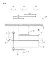
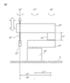
- FIG. 1A is a side view of the horizontal articulated robot according to the first embodiment.
- the robot 10 shown in FIG. 1A is a horizontal articulated robot and is suspended from the ceiling C of the room R.
- the robot 10 has a fixing portion 20 to be fixed to the ceiling C, a first arm 21 rotatably attached to the fixing portion 20, and a second arm 22 rotatably attached to the first arm 21. It mainly includes a working shaft portion 25 provided on the second arm 22.
- the proximal end of the first arm 21 is rotatably supported by the fixed portion 20 around the first rotation axis A1. Further, the distal end of the first arm 21 is rotatably supported by the proximal end of the second arm 22 around the second rotation axis A2 parallel to the first rotation axis A1. Therefore, when the robot 10 is suspended, the second arm 22 is located below the first arm 21. Therefore, the rotating surface of the first arm 21 and the rotating surface of the second arm 22 are displaced in the vertical direction and do not interfere with each other.
- the working shaft portion 25 is attached to the distal end of the second arm 22.
- the work shaft portion 25 is rotatably and vertically attached around the third rotation axis A3 parallel to the second rotation axis A2.
- the end effector (described later) to be attached to the distal end of the work shaft portion 25 performs a predetermined operation below the second arm 22.
- the first motor and the first speed reducer for driving the first arm 21 are arranged in the fixed portion 20.
- the second motor and the second speed reducer for driving the second arm 22 are arranged at predetermined positions of the first arm 21.
- a third motor for raising / lowering and rotating the work shaft portion 25 is arranged at a predetermined position on the second arm 22.
- first motors to third motors, first speed reducers, and second speed reducers may be provided in other places of the robot 10.
- the second motor and / or the second speed reducer may be arranged in a coupling portion 23 (described later) provided between the first arm 21 and the second arm 22. Since the basic configuration of the robot 10 is known, detailed description thereof will be omitted.
- the second distance L1 between the first rotation axis A1 and the second rotation axis A2 is the first distance between the second rotation axis A2 and the third rotation axis A3. It is shorter than the distance L2. In other words, the second arm 22 is longer than the first arm 21.
- the proximal end of the work shaft portion 25 projects from the upper surface of the second arm 22 toward the fixed portion 21.
- the protruding length of the working shaft portion 25 is longer than the third distance L3 between the first arm 21 and the second arm 22 on the second rotation axis A2.
- the first arm 21 and the second arm 22 of the robot 10 are arranged so as to extend in opposite directions to each other. Even in such a case, since the second arm 22 is longer than the first arm 21, the protruding portion of the working shaft portion 25 protruding from the second arm 22 toward the fixed portion 20 interferes with the first arm 21. There is nothing to do. In other words, in the present embodiment, the working shaft portion 25 having a protruding portion longer than the third distance L3 can be adopted. As described above, since the long working shaft portion 25 can be adopted, the stroke of the working shaft portion 25 is also long, and the movable range of the robot 10 can be widened.
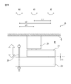
- FIG. 1B is a side view of the horizontal articulated robot in another embodiment.
- the proximal end of the offset member 26 is rotatably attached to the distal end of the working shaft portion 25.
- the offset member 26 extends perpendicular to the working shaft portion 25 and the third rotation axis A3. In other words, the offset member 26 extends parallel to the second arm 22 on the lower surface side of the second arm 22. Further, an end effector 27 is attached to the distal end of the offset member 26.
- the fourth distance is L4.
- the length of the offset member 26 is the fourth distance L4 or more.
- the distal end of the offset member 26 makes the first rotation on the lower surface side of the second arm 22. It comes to reach the axis A1. Therefore, the end effector 27 can be reached on the first rotation axis A1. Therefore, in the present embodiment, it is possible to prevent a dead zone from being generated around the first rotation axis A1.
- FIG. 2 is a side view of the horizontal articulated robot in the modified example of the first embodiment.
- a coupling portion 23 is provided between the first arm 21 and the second arm 22.
- the coupling portion 23 may be integrated with either the first arm 21 or the second arm 22.
- the connecting portion 23 is advantageous for alleviating the twist of the striatum (not shown) extending from the fixing portion 20 through the first arm 21.
- the third distance L3a between the first arm 21 and the second arm 22 on the second rotation axis A2 substantially corresponds to the height of the coupling portion 23.
- the protruding length L3a or more of the working shaft portion 25 protruding from the second arm 22 can be made, and therefore a longer working shaft portion 25 can be adopted.
- the robot 10 in another embodiment described later may have a similar coupling portion 23, and even in such a case, it is included in the scope of the present disclosure.
- FIG. 3 is a side view of the horizontal articulated robot in the second embodiment.
- the fixing portion 20 of the robot 10 similar to that described above is fixed to the floor portion L of the room R. Therefore, in the state of FIG. 3, the second arm 22 is located above the first arm 21.
- the second arm 22 is longer than the first arm 21. Therefore, it is possible to employ a longer working shaft portion 25 that extends downward beyond the upper surface of the first arm 21. As a result, the movable range of the robot 10 can be widened.
- a proximal end of the offset member 26 similar to that described above is rotatably attached to the distal end of the work shaft portion 25.
- the length of the offset member 26 is set between the first rotation axis A1 and the third rotation axis A3 when the first arm 21 and the second arm 22 are arranged so as to extend in opposite directions.
- the fourth distance is L4 or more. Therefore, the end effector 27 attached to the distal end of the offset member 26 can reach the first rotation axis A1 above the second arm 22. Therefore, it is possible to prevent the occurrence of a dead zone.
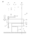
- FIG. 4A is a side view of the horizontal articulated robot in the third embodiment.
- the robot 10 shown in FIG. 4A is suspended from a gantry 40.
- the gantry 40 includes a column 41 extending vertically from the floor L and a beam 42 extending horizontally from the column 41. Then, the fixing portion 20 of the robot 10 is fixed to the lower surface on the distal side of the beam 42.
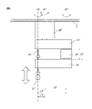
- FIG. 4B is a side view of another horizontal articulated robot according to the third embodiment.
- the robot 10 shown in FIG. 4B is suspended from the distal lower surface of another beam-shaped pedestal 45 extending from the wall portion W.
- FIG. 5 is a side view of the horizontal articulated robot in still another embodiment.
- the offset member 26 shown in FIG. 5 includes an end effector 27 and a drive unit 28 for driving the end effector 27, for example, a servomotor.
- the drive unit 28 may be provided on the opposite side of the end effector 27, or may be built in the end effector 27. By providing such a drive unit 28, the end effector 27 can perform an additional operation, for example, a screw tightening operation.
- FIG. 6 is a side view of a horizontal articulated robot in the prior art.
- the suspended horizontal articulated robot 10'shown in FIG. 6 includes a fixed portion 20', a first arm 21'that is rotatably supported by the fixed portion around the first rotation axis A1', and a second arm.
- the second arm 22' which is rotatably supported by the first arm 21'around the rotation axis A2', and the work shaft portion 25, which is rotatably and vertically attached around the third rotation axis A3'.
- 'And is included.
- the lengths of the first arm 21'and the second arm 22' are equal to each other.
- Axis lines A1' are equal to each other. Therefore, the length of the working shaft portion 25'is determined according to the height of the coupling portion 23', and the working shaft portion 25'cannot exceed the lower surface of the first arm 21'. That is, there is a problem that the work shaft portion 25'cannot be secured for a long time. Further, when the connecting portion 23'is not present, the length of the working shaft portion 25'is further limited.
- FIG. 7 is a side view of the horizontal articulated robot in the prior art.
- the floor-standing horizontal articulated robot 10 ′′ shown in FIG. 7 has a fixed portion 20 ′′ and a first arm 21 ′′ that is rotatably supported by the fixed portion around the first rotation axis A1 ′′.
- the second arm 22'' that is rotatably supported by the first arm 21'' around the second rotation axis A2'', and the second arm 22'' that can rotate and move up and down around the third rotation axis A3''.
- the work shaft portion 25 ′′ is not provided with an offset member. Therefore, the end effector 27 ′′ provided on the working shaft portion 25 ′′ cannot move in the vicinity of the first rotation axis A1 ′′ even in the illustrated state, and there is a problem that a dead zone exists.
- the fixed portion (20) and the first rotation axis are provided.
- a work shaft portion (25) mounted so as to be rotatable and elevating is provided, and the first distance (L1) between the first rotation axis and the second rotation axis is the second rotation. It is set to be shorter than the second distance (L2) between the moving axis and the third rotation axis, and the protruding length of the working shaft portion that can protrude from the second arm toward the fixed portion is Provided is a horizontal articulated robot having a length longer than the third distance (L3) between the first arm and the second arm on the second rotation axis.
- the offset member (26) rotatably supported by the working shaft portion at the distal end of the working shaft portion is further provided, and the third aspect is described.
- the length of the offset member extending vertically from the driving axis is the first between the first rotating axis and the third rotating axis when the first arm and the second arm extend in opposite directions to each other. It was made to be four distances (L4) or more.
- the coupling portion (23) arranged between the first arm and the second arm is further provided.
- the fixed portion (20) and the first arm (21) rotatably supported by the fixed portion around the first rotation axis (A1).
- the second arm (22) rotatably supported by the first arm around the second rotation axis (A2) parallel to the first rotation axis on the side farther from the fixed portion.
- a working shaft portion (25) rotatably and vertically attached to the second arm around the third rotation axis (A3) parallel to the second rotation axis.
- the first distance (L1) between the first rotation axis and the second rotation axis is larger than the second distance (L2) between the second rotation axis and the third rotation axis.
- the protruding length of the working shaft portion that can be projected from the second arm toward the fixed portion is a second arm between the first arm and the second arm on the second rotation axis. It is made longer than the three distances (L3), and further includes an offset member (26) rotatably supported by the work shaft portion at the distal end of the work shaft portion, and the third rotation.
- the length of the offset member extending vertically from the axis is the fourth between the first rotation axis and the third rotation axis when the first arm and the second arm extend in opposite directions to each other.
- a horizontal articulated robot is provided with a distance (L4) or greater.
- the coupling portion (23) arranged between the first arm and the second arm is further provided.
- the end effector (27) attached to the distal end of the offset member and the end effector attached to the end effector are further mounted.
- a drive unit (28) for driving is provided.
- the robot is suspended from a gantry (40, 45) or a ceiling (C).
- the robot is installed on the floor portion (L).
- the working shaft portion can project beyond the height of the lower surface of the first arm toward the fixed portion. Therefore, the work shaft portion itself can be secured for a long time, and the stroke of the work shaft portion can be lengthened.
- the working shaft portion since the first distance is shorter than the second distance, the working shaft portion can project beyond the height of the lower surface of the first arm toward the fixed portion. Therefore, the work shaft portion itself can be secured for a long time, and the stroke of the work shaft portion can be lengthened.
- the offset member is at least the fourth distance, the end effector can be reached on the first rotation axis. Therefore, it is possible to prevent a dead zone from being generated around the first rotation axis.
- Robot 20 Fixed part 21 First arm 22 Second arm 23 Coupling part 25 Work shaft part 26 Offset member 27 End effector 28 Drive part 40 Stand 41 Column 42 Beam 45 Stand
Landscapes
- Engineering & Computer Science (AREA)
- Robotics (AREA)
- Mechanical Engineering (AREA)
- Manipulator (AREA)
Abstract
Description
図1Aは第一の実施形態における水平多関節ロボットの側面図である。図1Aに示されるロボット10は、水平多関節ロボットであり、部屋Rの天井Cから吊下げられている。ロボット10は天井Cに固定されるべき固定部20と、固定部20に回動可能に取付けられた第一アーム21と、第一アーム21に回動可能に取付けられた第二アーム22と、第二アーム22に備えられた作業軸部25とを主に含んでいる。
1番目の態様によれば、架台(40、45)または天井(C)から吊下げられている水平多関節ロボット(10)において、固定部(20)と、第一回動軸線(A1)回りにおいて前記固定部に回動可能に支持される第一アーム(21)と、前記固定部よりも遠方側で、前記第一回動軸線に対して平行な第二回動軸線(A2)回りにおいて前記第一アームに回動可能に支持される第二アーム(22)と、前記第二回動軸線に対して平行な第三回動軸線(A3)回りにおいて前記第二アームに回転可能且つ昇降可能に取付けられた作業軸部(25)と、を具備し、前記第一回動軸線と前記第二回動軸線との間の第一距離(L1)は、前記第二回動軸線と前記第三回動軸線との間の第二距離(L2)よりも短いようにしており、前記第二アームから前記固定部に向かって突出可能な前記作業軸部の突出長さは前記第二回動軸線における前記第一アームと前記第二アームとの間の第三距離(L3)よりも長いようにした、水平多関節ロボットが提供される。
2番目の態様によれば、1番目の態様において、さらに、前記作業軸部の遠位端において前記作業軸部に回動可能に支持されるオフセット部材(26)を具備し、前記第三回動軸線から垂直に延びる前記オフセット部材の長さは、前記第一アームと前記第二アームとが互いに反対方向に延びるときの前記第一回動軸線と前記第三回動軸線との間の第四距離(L4)以上であるようにした。
3番目の態様によれば、1番目または2番目の態様において、さらに、前記第一アームと前記第二アームとの間に配置された結合部(23)を具備する。
4番目の態様によれば、1番目から3番目のいずれかの態様において、さらに、前記オフセット部材の遠位端に取付けられたエンドエフェクタ(27)と、該エンドエフェクタに取付けられていて、該エンドエフェクタを駆動する駆動部(28)とを具備する。
5番目の態様によれば、水平多関節ロボット(10)において、固定部(20)と、第一回動軸線(A1)回りにおいて前記固定部に回動可能に支持される第一アーム(21)と、前記固定部よりも遠方側で、前記第一回動軸線に対して平行な第二回動軸線(A2)回りにおいて前記第一アームに回動可能に支持される第二アーム(22)と、前記第二回動軸線に対して平行な第三回動軸線(A3)回りにおいて前記第二アームに回転可能且つ昇降可能に取付けられた作業軸部(25)と、を具備し、前記第一回動軸線と前記第二回動軸線との間の第一距離(L1)は、前記第二回動軸線と前記第三回動軸線との間の第二距離(L2)よりも短いようにしており、前記第二アームから前記固定部に向かって突出可能な前記作業軸部の突出長さは前記第二回動軸線における前記第一アームと前記第二アームとの間の第三距離(L3)よりも長いようにしており、さらに、前記作業軸部の遠位端において前記作業軸部に回動可能に支持されるオフセット部材(26)を具備し、前記第三回動軸線から垂直に延びる前記オフセット部材の長さは、前記第一アームと前記第二アームとが互いに反対方向に延びるときの前記第一回動軸線と前記第三回動軸線との間の第四距離(L4)以上であるようにした、水平多関節ロボットが提供される。
6番目の態様によれば、5番目の態様において、さらに、前記第一アームと前記第二アームとの間に配置された結合部(23)を具備する。
7番目の態様によれば、5番目または6番目の態様において、さらに、前記オフセット部材の遠位端に取付けられたエンドエフェクタ(27)と、該エンドエフェクタに取付けられていて、該エンドエフェクタを駆動する駆動部(28)とを具備する。
8番目の態様によれば、5番目から7番目のいずれかの態様において、前記ロボットは架台(40、45)もしくは天井(C)から吊下げられている。
9番目の態様によれば、5番目から7番目のいずれかの態様において、前記ロボットは床部(L)に設置されている。
1番目の態様においては、第一距離が第二距離よりも短いので、作業軸部は第一アームの下面の高さを越えて固定部に向かって突出できる。従って、作業軸部自体を長く確保でき、作業軸部のストロークを長くすることができる。
5番目の態様においては、第一距離が第二距離よりも短いので、作業軸部は第一アームの下面の高さを越えて固定部に向かって突出できる。従って、作業軸部自体を長く確保でき、作業軸部のストロークを長くすることができる。さらに、オフセット部材が第四距離以上であるので、エンドエフェクタを第一回動軸線上まで到達させられる。このため、第一回動軸線周りにデッドゾーンが発生するのを防止できる。
20 固定部
21 第一アーム
22 第二アーム
23 結合部
25 作業軸部
26 オフセット部材
27 エンドエフェクタ
28 駆動部
40 架台
41 カラム
42 ビーム
45 架台
Claims (9)
- 架台または天井から吊下げられている水平多関節ロボットにおいて、
固定部と、
第一回動軸線回りにおいて前記固定部に回動可能に支持される第一アームと、
前記固定部よりも遠方側で、前記第一回動軸線に対して平行な第二回動軸線回りにおいて前記第一アームに回動可能に支持される第二アームと、
前記第二回動軸線に対して平行な第三回動軸線回りにおいて前記第二アームに回転可能且つ昇降可能に取付けられた作業軸部と、を具備し、
前記第一回動軸線と前記第二回動軸線との間の第一距離は、前記第二回動軸線と前記第三回動軸線との間の第二距離よりも短いようにしており、
前記第二アームから前記固定部に向かって突出可能な前記作業軸部の突出長さは前記第二回動軸線における前記第一アームと前記第二アームとの間の第三距離よりも長いようにした、水平多関節ロボット。 - さらに、前記作業軸部の遠位端において前記作業軸部に回動可能に支持されるオフセット部材を具備し、
前記第三回動軸線から垂直に延びる前記オフセット部材の長さは、前記第一アームと前記第二アームとが互いに反対方向に延びるときの前記第一回動軸線と前記第三回動軸線との間の第四距離以上であるようにした、請求項1に記載の水平多関節ロボット。 - さらに、前記第一アームと前記第二アームとの間に配置された結合部を具備する、請求項1または2に記載の水平多関節ロボット。
- さらに、前記オフセット部材の遠位端に取付けられたエンドエフェクタと、
該エンドエフェクタに取付けられていて、該エンドエフェクタを駆動する駆動部とを具備する請求項1から3のいずれか一項に記載の水平多関節ロボット。 - 水平多関節ロボットにおいて、
固定部と、
第一回動軸線回りにおいて前記固定部に回動可能に支持される第一アームと、
前記固定部よりも遠方側で、前記第一回動軸線に対して平行な第二回動軸線回りにおいて前記第一アームに回動可能に支持される第二アームと、
前記第二回動軸線に対して平行な第三回動軸線回りにおいて前記第二アームに回転可能且つ昇降可能に取付けられた作業軸部と、を具備し、
前記第一回動軸線と前記第二回動軸線との間の第一距離は、前記第二回動軸線と前記第三回動軸線との間の第二距離よりも短いようにしており、
前記第二アームから前記固定部に向かって突出可能な前記作業軸部の突出長さは前記第二回動軸線における前記第一アームと前記第二アームとの間の第三距離よりも長いようにしており、
さらに、前記作業軸部の遠位端において前記作業軸部に回動可能に支持されるオフセット部材を具備し、
前記第三回動軸線から垂直に延びる前記オフセット部材の長さは、前記第一アームと前記第二アームとが互いに反対方向に延びるときの前記第一回動軸線と前記第三回動軸線との間の第四距離以上であるようにした、水平多関節ロボット。 - さらに、前記第一アームと前記第二アームとの間に配置された結合部を具備する、請求項5に記載の水平多関節ロボット。
- さらに、前記オフセット部材の遠位端に取付けられたエンドエフェクタと、
該エンドエフェクタに取付けられていて、該エンドエフェクタを駆動する駆動部とを具備する請求項5または6に記載の水平多関節ロボット。 - 前記ロボットは架台もしくは天井から吊下げられている、請求項5から7のいずれか一項に記載の水平多関節ロボット。
- 前記ロボットは床部に設置されている、請求項5から7のいずれか一項に記載の水平多関節ロボット。
Priority Applications (4)
| Application Number | Priority Date | Filing Date | Title |
|---|---|---|---|
| JP2022560791A JP7553593B2 (ja) | 2020-11-06 | 2021-11-02 | 水平多関節ロボット |
| US18/251,370 US12576512B2 (en) | 2020-11-06 | 2021-11-02 | Horizontal articulated robot |
| CN202180071804.9A CN116490327A (zh) | 2020-11-06 | 2021-11-02 | 水平多关节机器人 |
| DE112021004573.3T DE112021004573T5 (de) | 2020-11-06 | 2021-11-02 | Horizontaler gelenkarmroboter |
Applications Claiming Priority (2)
| Application Number | Priority Date | Filing Date | Title |
|---|---|---|---|
| JP2020186139 | 2020-11-06 | ||
| JP2020-186139 | 2020-11-06 |
Publications (1)
| Publication Number | Publication Date |
|---|---|
| WO2022097649A1 true WO2022097649A1 (ja) | 2022-05-12 |
Family
ID=81457290
Family Applications (1)
| Application Number | Title | Priority Date | Filing Date |
|---|---|---|---|
| PCT/JP2021/040421 Ceased WO2022097649A1 (ja) | 2020-11-06 | 2021-11-02 | 水平多関節ロボット |
Country Status (6)
| Country | Link |
|---|---|
| US (1) | US12576512B2 (ja) |
| JP (1) | JP7553593B2 (ja) |
| CN (1) | CN116490327A (ja) |
| DE (1) | DE112021004573T5 (ja) |
| TW (1) | TWI911313B (ja) |
| WO (1) | WO2022097649A1 (ja) |
Families Citing this family (1)
| Publication number | Priority date | Publication date | Assignee | Title |
|---|---|---|---|---|
| JP2024143745A (ja) * | 2023-03-30 | 2024-10-11 | 川崎重工業株式会社 | ロボット |
Citations (5)
| Publication number | Priority date | Publication date | Assignee | Title |
|---|---|---|---|---|
| JPH0192077A (ja) * | 1987-09-30 | 1989-04-11 | Pentel Kk | 平行2軸旋回型ロボット |
| JPH01115586A (ja) * | 1987-10-30 | 1989-05-08 | Pentel Kk | 平行2軸旋回型ロボット |
| JPH06262555A (ja) * | 1993-03-17 | 1994-09-20 | Toshiba F Ee Syst Eng Kk | 産業用ロボット |
| JP2003220586A (ja) * | 2002-01-22 | 2003-08-05 | Nissin Electric Co Ltd | 物品搬送ロボット及び真空処理装置 |
| JP2016500473A (ja) * | 2012-11-30 | 2016-01-12 | アプライド マテリアルズ インコーポレイテッドApplied Materials,Incorporated | 不等長の前腕部を備えた多軸ロボット装置、電子デバイス製造システム、及び、電子デバイス製造において基板を搬送するための方法 |
Family Cites Families (19)
| Publication number | Priority date | Publication date | Assignee | Title |
|---|---|---|---|---|
| JPS528323B1 (ja) | 1971-04-16 | 1977-03-08 | ||
| EP0000877B1 (de) * | 1977-08-31 | 1983-05-18 | Grisebach, Hans-Theodor | Manipulator zum Positionieren von Werkstücken oder anderen Lasten |
| JPS59136282U (ja) * | 1983-03-03 | 1984-09-11 | 中西機械株式会社 | 多関節ロボツト |
| DE3626610A1 (de) * | 1986-08-06 | 1988-02-18 | Fibro Gmbh | Portalsystem |
| JP3042769B2 (ja) | 1996-09-11 | 2000-05-22 | タナシン電機株式会社 | ディスク再生装置 |
| JPH1115586A (ja) | 1997-06-24 | 1999-01-22 | Roasu Kk | テンキーボード |
| JP2005193347A (ja) | 2004-01-09 | 2005-07-21 | Seiko Epson Corp | 水平多関節型ロボット |
| US9248568B2 (en) * | 2005-07-11 | 2016-02-02 | Brooks Automation, Inc. | Unequal link SCARA arm |
| JP4864378B2 (ja) | 2005-08-11 | 2012-02-01 | 東芝機械株式会社 | 塗装ロボット |
| JP4873946B2 (ja) | 2005-12-21 | 2012-02-08 | Idec株式会社 | 組立装置 |
| JP2008213060A (ja) * | 2007-03-01 | 2008-09-18 | Honda Motor Co Ltd | 多関節ロボット |
| KR20130043678A (ko) | 2010-09-03 | 2013-04-30 | 미쓰비시덴키 가부시키가이샤 | 천장 매닮 스칼라형 로봇 |
| JP6262555B2 (ja) | 2014-02-06 | 2018-01-17 | 東洋ゴム工業株式会社 | 空気ばね |
| JP6506324B2 (ja) * | 2017-02-16 | 2019-04-24 | ファナック株式会社 | 水平多関節型ロボットとその設置反転方法 |
| JP2018161726A (ja) * | 2017-03-27 | 2018-10-18 | セイコーエプソン株式会社 | ロボット制御装置、ロボット、及びロボットシステム |
| JP6917920B2 (ja) * | 2018-02-19 | 2021-08-11 | 株式会社東芝 | 搬送システム、及び搬送方法 |
| WO2019196068A1 (en) * | 2018-04-12 | 2019-10-17 | Abb Schweiz Ag | Robot of scara type and method for manufacturing the robot |
| JP7191564B2 (ja) * | 2018-07-03 | 2022-12-19 | 日本電産サンキョー株式会社 | 産業用ロボット |
| KR20200031188A (ko) * | 2018-09-13 | 2020-03-24 | 안상진 | 수평 다관절 로봇 |
-
2021
- 2021-10-27 TW TW110139833A patent/TWI911313B/zh active
- 2021-11-02 CN CN202180071804.9A patent/CN116490327A/zh active Pending
- 2021-11-02 JP JP2022560791A patent/JP7553593B2/ja active Active
- 2021-11-02 US US18/251,370 patent/US12576512B2/en active Active
- 2021-11-02 DE DE112021004573.3T patent/DE112021004573T5/de active Pending
- 2021-11-02 WO PCT/JP2021/040421 patent/WO2022097649A1/ja not_active Ceased
Patent Citations (5)
| Publication number | Priority date | Publication date | Assignee | Title |
|---|---|---|---|---|
| JPH0192077A (ja) * | 1987-09-30 | 1989-04-11 | Pentel Kk | 平行2軸旋回型ロボット |
| JPH01115586A (ja) * | 1987-10-30 | 1989-05-08 | Pentel Kk | 平行2軸旋回型ロボット |
| JPH06262555A (ja) * | 1993-03-17 | 1994-09-20 | Toshiba F Ee Syst Eng Kk | 産業用ロボット |
| JP2003220586A (ja) * | 2002-01-22 | 2003-08-05 | Nissin Electric Co Ltd | 物品搬送ロボット及び真空処理装置 |
| JP2016500473A (ja) * | 2012-11-30 | 2016-01-12 | アプライド マテリアルズ インコーポレイテッドApplied Materials,Incorporated | 不等長の前腕部を備えた多軸ロボット装置、電子デバイス製造システム、及び、電子デバイス製造において基板を搬送するための方法 |
Also Published As
| Publication number | Publication date |
|---|---|
| TW202218831A (zh) | 2022-05-16 |
| DE112021004573T5 (de) | 2023-06-22 |
| US20240051118A1 (en) | 2024-02-15 |
| CN116490327A (zh) | 2023-07-25 |
| TWI911313B (zh) | 2026-01-11 |
| JPWO2022097649A1 (ja) | 2022-05-12 |
| US12576512B2 (en) | 2026-03-17 |
| JP7553593B2 (ja) | 2024-09-18 |
Similar Documents
| Publication | Publication Date | Title |
|---|---|---|
| JP6500344B2 (ja) | 天吊りロボット | |
| US9003919B2 (en) | Ceiling-mounted scara robot | |
| TW200932456A (en) | Multijoint robot | |
| JP5272647B2 (ja) | ロボット | |
| JP6582491B2 (ja) | ロボット | |
| WO2017002208A1 (ja) | ロボットシステム | |
| JP2014069288A (ja) | ロボットアームおよびロボット | |
| JP2022044794A (ja) | ロボット装置 | |
| JP2015211998A (ja) | ロボット | |
| CN106002933A (zh) | 机器人系统 | |
| WO2022097649A1 (ja) | 水平多関節ロボット | |
| JP2007118177A (ja) | 双腕ロボット | |
| JP4044046B2 (ja) | 3本の平行ブランチを備えたコントローラー | |
| CN1819902A (zh) | 工业机器人 | |
| WO2019163997A1 (ja) | パラレルリンク機構を用いた作業装置およびその制御方法 | |
| JP2021010992A (ja) | 移動ロボット | |
| JP2000126954A (ja) | パラレルリンク機構に用いるケーブル、配管の処理構造 | |
| KR20130031264A (ko) | 천장매닮 스칼라형 로봇 | |
| CN119188793A (zh) | 涂装机器人 | |
| JP7481941B2 (ja) | ロボットおよびロボットシステム | |
| JP7069757B2 (ja) | 水平多関節ロボット | |
| KR101312003B1 (ko) | R축을 포함한 로봇의 보간 방법 | |
| JP7289644B2 (ja) | 作業装置 | |
| JP2012187667A (ja) | 多関節型ロボット | |
| JPH0871963A (ja) | 産業用ロボット |
Legal Events
| Date | Code | Title | Description |
|---|---|---|---|
| 121 | Ep: the epo has been informed by wipo that ep was designated in this application |
Ref document number: 21889202 Country of ref document: EP Kind code of ref document: A1 |
|
| ENP | Entry into the national phase |
Ref document number: 2022560791 Country of ref document: JP Kind code of ref document: A |
|
| WWE | Wipo information: entry into national phase |
Ref document number: 202180071804.9 Country of ref document: CN |
|
| 122 | Ep: pct application non-entry in european phase |
Ref document number: 21889202 Country of ref document: EP Kind code of ref document: A1 |