WO2022097477A1 - 気泡測定装置及び気泡測定方法 - Google Patents
気泡測定装置及び気泡測定方法 Download PDFInfo
- Publication number
- WO2022097477A1 WO2022097477A1 PCT/JP2021/038746 JP2021038746W WO2022097477A1 WO 2022097477 A1 WO2022097477 A1 WO 2022097477A1 JP 2021038746 W JP2021038746 W JP 2021038746W WO 2022097477 A1 WO2022097477 A1 WO 2022097477A1
- Authority
- WO
- WIPO (PCT)
- Prior art keywords
- bubbles
- bubble
- liquid
- flow rate
- imaging surface
- Prior art date
- Legal status (The legal status is an assumption and is not a legal conclusion. Google has not performed a legal analysis and makes no representation as to the accuracy of the status listed.)
- Ceased
Links
Images




Classifications
-
- G—PHYSICS
- G01—MEASURING; TESTING
- G01N—INVESTIGATING OR ANALYSING MATERIALS BY DETERMINING THEIR CHEMICAL OR PHYSICAL PROPERTIES
- G01N15/00—Investigating characteristics of particles; Investigating permeability, pore-volume or surface-area of porous materials
- G01N15/02—Investigating particle size or size distribution
- G01N15/0205—Investigating particle size or size distribution by optical means
- G01N15/0227—Investigating particle size or size distribution by optical means using imaging; using holography
-
- G—PHYSICS
- G01—MEASURING; TESTING
- G01N—INVESTIGATING OR ANALYSING MATERIALS BY DETERMINING THEIR CHEMICAL OR PHYSICAL PROPERTIES
- G01N15/00—Investigating characteristics of particles; Investigating permeability, pore-volume or surface-area of porous materials
- G01N15/10—Investigating individual particles
- G01N15/14—Optical investigation techniques, e.g. flow cytometry
- G01N15/1429—Signal processing
- G01N15/1433—Signal processing using image recognition
-
- G—PHYSICS
- G01—MEASURING; TESTING
- G01N—INVESTIGATING OR ANALYSING MATERIALS BY DETERMINING THEIR CHEMICAL OR PHYSICAL PROPERTIES
- G01N15/00—Investigating characteristics of particles; Investigating permeability, pore-volume or surface-area of porous materials
- G01N15/10—Investigating individual particles
- G01N15/14—Optical investigation techniques, e.g. flow cytometry
- G01N15/1456—Optical investigation techniques, e.g. flow cytometry without spatial resolution of the texture or inner structure of the particle, e.g. processing of pulse signals
- G01N15/1459—Optical investigation techniques, e.g. flow cytometry without spatial resolution of the texture or inner structure of the particle, e.g. processing of pulse signals the analysis being performed on a sample stream
-
- G—PHYSICS
- G01—MEASURING; TESTING
- G01N—INVESTIGATING OR ANALYSING MATERIALS BY DETERMINING THEIR CHEMICAL OR PHYSICAL PROPERTIES
- G01N15/00—Investigating characteristics of particles; Investigating permeability, pore-volume or surface-area of porous materials
- G01N2015/0007—Investigating dispersion of gas
- G01N2015/0011—Investigating dispersion of gas in liquids, e.g. bubbles
-
- G—PHYSICS
- G01—MEASURING; TESTING
- G01N—INVESTIGATING OR ANALYSING MATERIALS BY DETERMINING THEIR CHEMICAL OR PHYSICAL PROPERTIES
- G01N15/00—Investigating characteristics of particles; Investigating permeability, pore-volume or surface-area of porous materials
- G01N15/10—Investigating individual particles
- G01N15/14—Optical investigation techniques, e.g. flow cytometry
- G01N2015/1486—Counting the particles
-
- G—PHYSICS
- G01—MEASURING; TESTING
- G01N—INVESTIGATING OR ANALYSING MATERIALS BY DETERMINING THEIR CHEMICAL OR PHYSICAL PROPERTIES
- G01N15/00—Investigating characteristics of particles; Investigating permeability, pore-volume or surface-area of porous materials
- G01N15/10—Investigating individual particles
- G01N15/14—Optical investigation techniques, e.g. flow cytometry
- G01N2015/1493—Particle size
Definitions
- the present invention relates to a bubble measuring device and a bubble measuring method.
- the contact between mineral particles in the ore slurry and bubbles is an important mechanism. It is known that the bubble diameter is an important factor for the contact probability, and attempts have been made to grasp the bubble diameter. In particular, fine bubbles having a bubble diameter of 1 to 100 ⁇ m are called microbubbles, and are expected to have potential applications. However, the buoyancy of fine bubbles is very small, and there is a problem that it is difficult to introduce fine bubbles into an image pickup cell, which is an area for measuring bubbles, with a conventional bubble measuring device.
- Patent Document 1 As a method for solving this problem, for example, the method shown in Patent Document 1 is disclosed.
- the method described in Patent Document 1 is an image capturing unit that photographs a bubble to be measured, and a light intensity measuring unit that irradiates the bubble with laser light to acquire light intensity distribution data showing the intensity distribution of diffracted / scattered light.
- a pump By connecting a pump to the image pickup unit and operating this pump, the liquid containing the air bubbles to be measured is sent to the image pickup unit and the light intensity measurement unit, and the image information acquired from the image capture unit and the light.
- This is a method of measuring the particle size distribution of a bubble group based on the light intensity distribution data acquired from the intensity measuring unit. By such a method, the particle size distribution of the bubble group can be measured.
- the liquid contains foreign substances other than bubbles in addition to the bubbles to be measured.
- this discrimination is performed based on the image information acquired from the image measuring unit.
- a mechanical method is used in which a spherical image is determined to be a bubble and a flat image is determined to be a foreign substance.
- the image used for the determination is clearly captured to such an extent that the determination can be made appropriately.
- the captured image of the bubble becomes a flat image and is determined to be a foreign substance, so that an appropriate determination cannot be made.
- Patent Document 1 does not disclose a method for taking a clear image.
- an object of the present invention is to provide a bubble measuring device and a bubble measuring method capable of clearly photographing and measuring minute bubbles.
- the invention is a bubble measuring device for measuring bubbles moving in a liquid.
- a measurement chamber in which a liquid containing bubbles to be measured is introduced from below and an imaging surface is provided at a position where the introduced bubbles rise.
- An imaging device that photographs the bubbles passing through the imaging surface, and An introduction tube provided below the measurement chamber and introducing the air bubbles into the measurement chamber,
- a supply pump provided above the measurement chamber, which sucks up the liquid containing the bubbles and supplies it to the measurement chamber. It has a flow velocity adjusting mechanism for adjusting the flow velocity of the liquid passing through the imaging surface.
- the flow rate of the liquid passing through the imaging surface is adjusted by the flow rate adjusting mechanism according to the range in which the bubbles can be measured.
- the range is characterized in that it is obtained in advance according to the image resolution of the photographing apparatus and the shutter speed.
- fine bubbles can be clearly photographed and measured.
- FIG. 1 is a schematic view showing the configuration of the bubble measuring device according to the present embodiment.
- the bubble measuring device 1 according to the present embodiment includes an introduction tube 60, a frame 70, a measurement chamber 80, an introduction tube connecting member 81, a floodlight device 90, a photographing device 100, an image processing unit 110, and the like. It is a device including a control unit 120, a supply pump 20, a flow velocity adjusting mechanism 21, a lead-out pipe 40, and a discharge pipe 50, and the introduction pipe 60 is immersed in the liquid held in the holding tank 10.
- the introduction pipe 60 is connected below the measurement chamber 80 via the introduction pipe connecting member 81, and is provided so that the liquid can be sent to the measurement chamber 80.
- One surface (the surface facing upward) of the measurement chamber 80 forms an image pickup surface, and an image pickup device 100 is provided so as to face the image pickup surface. Further, the light projecting device 90 is provided so as to face the other surface (the surface facing downward) of the measurement chamber 80.
- a lead-out pipe 40 is connected to the upper end of the measurement chamber 80, and a supply pump 20 is provided at the upper end of the lead-out pipe 40.
- a discharge pipe 50 is connected to the lower surface of the supply pump 40, and the lower end of the discharge pipe 50 is immersed in the liquid in the holding tank 10. Further, a flow velocity adjusting mechanism 21 is connected to the supply pump 20.
- a bubble generator 30 for generating bubbles inside the liquid is connected to the holding tank 10.
- the bubble generating device 30 generates bubbles containing fine bubbles (hereinafter, also referred to as micro bubbles) having a bubble diameter of 1 to 100 ⁇ m inside the liquid. In that case, these bubbles can be clearly photographed. Then, the bubbles can be measured based on the captured image, that is, the bubble diameter and the bubble diameter distribution (particle size distribution of the bubble group) can be measured.
- the imaging and measurement of bubbles including microbubbles are specifically performed by going through the following steps.
- Step 1 in a state where bubbles containing microbubbles are generated inside the liquid held in the holding tank 10, the supply pump 20 of the bubble measuring device 1 is operated, and the liquid containing the bubbles generated by the bubble generating device 30 is operated. Is introduced into the measuring chamber 80 via the introduction pipe 60. In this case, the flow velocity of the liquid passing through the imaging surface in the measurement chamber 80 is adjusted by the flow velocity adjusting mechanism 21 so as to be within the flow velocity range in which bubbles including microbubbles can be clearly photographed. (Step 1) The details of adjusting the flow velocity in the flow velocity adjusting mechanism 21 will be described later.
- Step 2 Next, the light projecting device 90 irradiates the opposite surface of the photographing surface in the measuring chamber 80 with light, and the photographing device 100 is used to photograph bubbles passing through the photographing surface.
- Step 2 information necessary for measuring the bubble diameter and bubble diameter distribution of bubbles contained in the liquid is acquired from the captured image, and these values are measured.
- Step 3 the components constituting the bubble measuring device 1 will be further described.
- the introduction pipe 60 is a pipe material having both ends open. One end is immersed in the liquid held in the holding tank 10, and the other end is connected to the introduction pipe connecting member 81.
- the introduction pipe connecting member 81 In the present embodiment, in order to introduce the bubbles taken into the introduction tube 60 into the measurement chamber 80, not only the buoyancy of the bubbles themselves but also the power generated by operating the supply pump 20 described later is generated. It will be used.
- the measuring chamber 80 is composed of a plurality of transparent members.
- the material of these members is vinyl chloride.
- a member having a high light transmittance can be preferably used so that the light projected from the light projecting device 90 passes through the measuring chamber 80 and can be measured by the photographing device 100.
- the light transmittance of the member is preferably 80% or more, more preferably 90% or more in the visible light region having a wavelength of 400 nm to 700 mm.
- glass acrylic, polyethylene terephthalate (PET), polycarbonate or the like can be used in addition to vinyl chloride.
- vinyl chloride is inexpensive, highly processable, and highly transparent, it can be suitably used as a member of the measuring chamber 80.
- acrylic has higher transparency than vinyl chloride, is not easily scratched, and has less decrease in transparency, so that it can be suitably used for installation in places where replacement is difficult.
- the measuring chamber 80 is provided with a main member 82, and a first lid member 83 and a second lid member 84 so as to sandwich the main member 82.
- the outer shape of the main member 82 has a thick quadrangular plate shape, that is, a flat quadrangular prism shape.
- the main member 82 is provided with a measuring hole 82a having a relatively large diameter.
- the axial direction of the measuring hole 82a coincides with the thickness direction (hereinafter, this direction may be referred to as the thickness direction of the main member 82) of the thinnest thickness of the quadrangular prism form of the main member 82.
- the surface on the right side of the first lid member 83 is referred to as a transparent inclined surface, and among the transparent inclined surfaces, the surface is referred to as a transparent inclined surface.
- the portion where the measuring hole 82a is located is referred to as a measuring unit 83a.
- this transparent inclined surface corresponds to the photographing surface.
- the measuring chamber 80 is further composed of an introduction pipe connecting member 81 provided on the lower side of the main member 82 and a lead-out pipe connecting member 85 provided on the upper side of the main member 82, and is composed of the introduction pipe connecting member.
- the introduction pipe 60 is connected via 81.
- the introduction pipe connecting member 81 has a passage hole and both the introduction pipe connecting member 81 and the outlet pipe connecting member 85 have a tubular structure
- the measuring chamber 80 communicates in the vertical direction through these members. It has a structure. By communicating in this way, the liquid can be passed through the transparent inclined surface in the measurement chamber 80, that is, the photographing surface, and bubbles in the liquid can be introduced from the introduction tube 60.
- the upper surface of the introduction pipe connecting member 81 is tilted from the horizontal plane by an inclination angle ⁇ . Since the upper surface of the introduction pipe connecting member 81 is tilted in this way, when the measuring chamber 80 is arranged so that the axis of the introduction pipe connecting member 81 is in the vertical direction, the transparent inclined surface including the measuring portion 83a is formed. It tilts from the vertical by the tilt angle ⁇ . That is, the normal of the transparent inclined surface faces downward, and the transparent inclined surface faces diagonally downward.
- the inclination angle ⁇ is determined so that the transparent inclined surface is located at the position where the bubbles rising from the introduction port. In the present embodiment, the tilt angle ⁇ is 15 degrees, but it may be set to various angles depending on the application.
- the diameter L1 of the measuring hole 82a of the main member 82 constituting the bubble measuring device 1 of the present embodiment is longer than the diameter of the inner surface of the introduction pipe 60.
- the diameter L1 of the measuring hole 82a is the length in the left-right direction of the measuring portion 83a when the transparent inclined surface is viewed from the front.
- the main member 82 is provided with a measuring hole 82a as described above, and is provided with an expanded communication portion for communicating the measuring hole 82a with the introduction pipe 60.
- the extended communication portion has a groove shape.
- the length in the left-right direction up to the measuring portion 83a of the groove portion of the enlarged communication portion increases from the lower side to the upper side at a constant rate.
- the depth of the groove shape of the extended communication portion has a depth of 1/3 of the length in the thickness direction of the main member 82.
- the floodlight device 90 irradiates the measurement unit 83a with a predetermined type of light from one surface of the measurement chamber 80. This facilitates photography in the measurement chamber 80.
- the lighting means for example, surface lighting such as a white LED is preferably used.
- the photographing device 100 a digital camera or the like capable of photographing at least either a still image or a moving image is preferably used. It is preferable that the size and quantity of bubbles photographed by the imaging device 100 are analyzed by software that performs image processing.
- the photographing device 100 may use various photographing devices as long as the bubbles can be appropriately photographed.
- the photographing apparatus 100 has an image resolution capable of separating bubbles to be measured according to their sizes and photographing them.
- the image resolution is a value obtained by the following equation (1), and is a value indicating how many mm one pixel of the pixels arranged in a grid pattern on the image pickup device 100 of the photographing apparatus 100 corresponds to. be.
- the imaging field of view (Y direction) is 100 mm
- the image resolution of the photographing apparatus having 480 pixels in the Y direction is 100 [mm]
- ⁇ 480 pixels 0.208 [mm].
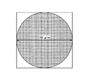
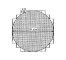
- FIG. 3A is a diagram showing a state of image recognition when a bubble having a bubble diameter of 10 ⁇ m is photographed by an imaging device having an image resolution of 10 ⁇ m
- FIG. 3B is a diagram showing the same bubble as described above with an imaging device having an image resolution of 1 ⁇ m. It is a figure which showed the state of the image recognition at the time of taking a picture in.
- FIG. 3A is a diagram showing a state of image recognition when a bubble having a bubble diameter of 10 ⁇ m is photographed by an imaging device having an image resolution of 10 ⁇ m
- FIG. 3B is a diagram
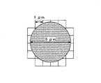
- FIG. 3C is a diagram showing a state of image recognition when a bubble having a bubble diameter of 5 ⁇ m is photographed by an imaging device having an image resolution of 10 ⁇ m
- FIG. 3D is a diagram showing the same bubble as described above with an image resolution of 1 ⁇ m. It is a figure which showed the state of image recognition at the time of taking a picture by an apparatus.
- both a bubble having a bubble diameter of 10 ⁇ m and a bubble having a bubble diameter of 5 ⁇ m are image-recognized as one pixel, that is, the bubble diameter is 10 ⁇ m or less. Bubbles are image-recognized as one pixel, and image recognition cannot be performed separately for each size.
- a photographing device having an image resolution of 1 ⁇ m as shown in FIGS. 3 (b) and 3 (d).
- a bubble having a bubble diameter of 10 ⁇ m is recognized as 91 pixels, and a bubble having a bubble diameter of 5 ⁇ m is recognized as 32 pixels, and the image can be recognized separately for each size. In this way, the smaller the image resolution, the more small bubbles can be separated from the large bubbles for image recognition.
- the photographing apparatus 100 has an image resolution capable of separating bubbles to be measured according to their sizes and photographing them. That is, the photographing apparatus 100 has an image resolution capable of recognizing the smallest bubble among the bubbles to be measured.
- the measurement target is a bubble containing microbubbles having a bubble diameter of 1 to 100 ⁇ m
- a photographing device having an image resolution of 1 ⁇ m is used. This makes it possible to separate bubbles of 1 ⁇ m or more for each size and perform image recognition.
- the image resolution of the photographing apparatus 100 does not have to be the same as the size of the smallest bubble among the bubbles to be measured, and may have a smaller value. This makes it possible to separate the bubbles to be measured for each size and perform image recognition.
- the photographing apparatus 100 does not have an image resolution capable of recognizing an image for each size of the bubble, the image of the captured bubble does not reflect the actual morphology of the bubble. It is not preferable to measure bubbles based on such an image.
- the exposure time (shutter speed) of the photographing apparatus 100 is set to the exposure time required for the brightness of the captured image to have a brightness sufficient for measuring bubbles. Has been done.
- the exposure time it is preferable that the exposure time is as short as possible. As a result, it is possible to prevent blurring of the captured bubble image.
- the exposure time is set to 1/2000 second.
- the supply pump 20 is a pump that sucks up the liquid containing bubbles from the holding tank 10 and supplies it to the measurement chamber 80.
- various pumps may be used as long as the liquid can be appropriately pumped.
- a tube pump provided with a roller for sending liquid inside is used as a supply pump 20, a discharge pipe 40 described later is connected to the suction side, and a discharge pipe 50 described later is connected to the discharge side.
- the flow velocity adjusting mechanism 21 adjusts the flow velocity of the liquid generated by operating the supply pump 20, and in this example, the drive device for driving the liquid feeding roller of the supply pump 20. Since is a brushless motor, an applied voltage control circuit for controlling the applied voltage to the brushless motor is used. By adjusting the applied voltage to the brushless motor using the applied voltage control circuit, the speed (rotation speed) of the brushless motor is adjusted, and the amount of liquid discharged from the supply pump 20, that is, the imaging surface of the measuring chamber 80 is measured. The flow velocity of the passing liquid is adjusted.
- the flow rate adjusting mechanism 21 may be any means as long as the amount of liquid discharged from the supply pump 20, that is, the flow rate of the liquid passing through the imaging surface of the measuring chamber 80 can be adjusted. More specifically, the type is not particularly limited as long as the speed of the drive device can be controlled according to the type of the drive device used in the supply pump 20. For example, when an AC motor is used for the drive device of the supply pump 20, it may be an inverter circuit for controlling the drive frequency of the AC motor, or when a servo motor is used for the drive device of the supply pump 20. , A driver circuit provided with a speed control unit of a servo motor or the like may be used. Further, the flow velocity adjusting mechanism 21 does not have to be provided independently, and may be provided so as to be included in one of the components of the supply pump 20, for example.
- the flow velocity of the liquid passing through the photographing surface of the measuring chamber 80 is set in advance in a range in which bubbles can be appropriately measured in the image resolution and the shutter speed of the photographing apparatus 100 to be used.
- the bubble measuring device 1 it is investigated how much the flow velocity can be measured by the photographing device 100. As described above, if the image resolution of the photographing apparatus 100 is small and the shutter speed is short, the fluid flow velocity is set high, but if the image resolution is large and the shutter speed is long, the fluid speed is set slow. In this case, consideration is given so that the flow velocity is such that the bubbles do not adhere to the photographing surface or coalesce the bubbles.
- a bubble generator having a known bubble diameter distribution particle size distribution of a bubble group
- the bubble diameter distribution generated from the bubble generator is measured, and the result is referred to as a known bubble diameter distribution. It can be done by comparison.
- the range of the flow velocity of the liquid capable of measuring bubbles is determined by the capacity of the photographing device 100, the flow rate of the fluid suitable for the photographing device 100 to be used is investigated in advance. Then, the flow velocity of the fluid corresponding to the imaging device 100 is determined, and in the actual bubble measurement, the flow velocity of the fluid passing through the imaging surface is set in a predetermined range or a predetermined value within the range. Thereby, in the actual bubble measurement, it is possible to set an appropriate flow velocity at which the bubble can be measured, and the bubble can be measured clearly.
- the flow velocity of the liquid passing through the photographing surface of the measuring chamber 80 is adjusted to 200 mm / sec with respect to the photographing apparatus 100 having an image resolution of 1 ⁇ m and an exposure time of 1/2000 seconds.
- the adjustment is made in the range of 100 to 200 mm / sec, which suppresses adhesion and coalescence of bubbles to the photographing surface and enables clear imaging of bubbles.
- parameters suitable for grasping the bubble state such as bubble diameter and bubble diameter distribution are selected and used as an index for grasping the bubble state.
- the control unit 120 is a means for controlling the supply pump 20 and the flow rate adjusting mechanism 21, and may be configured as, for example, a microprocessor having a CPU (Central Processing Unit) 121 and a memory 122.
- the memory 122 may store an appropriate flow velocity range of the fluid according to the photographing device 100, and the supply pump 20 and the fluid velocity adjusting mechanism 21 may be operated and controlled so that the fluid has an appropriate flow velocity range. ..
- control unit 120 may also control the operation of the light projecting device 90, the photographing device 100, the image processing device 110, the bubble generating device 30, and the like, if necessary.
- control unit 120 is not an essential configuration requirement and may be provided as needed.
- one end of the outlet pipe 40 is connected to the outlet pipe connecting member 85 of the measurement chamber 80, and the other end is connected to the suction side of the supply pump 20 to supply a liquid containing bubbles from the measurement chamber 80. It is a pipe material for transporting to the pump 20.
- one end of the discharge pipe 50 is connected to the discharge side of the supply pump 20, and the other end is immersed in the liquid held in the holding tank 10, and the liquid discharged from the supply pump 20 is immersed in the holding tank 10. It is a pipe material for transporting to.
- the frame 70 is a support member for supporting the measurement chamber 80, the light projecting device 90, and the photographing device 100.
- Example 1 After 18 L of fresh water was put into the holding tank, the bubble generator connected to the holding tank was operated to generate microbubbles in the fresh water.
- a bubble measuring device was prepared in which the image resolution of the photographing device was set to 1 ⁇ m and the exposure time (shutter speed) was set to 1/2000 seconds, the introduction tube was immersed in fresh water, and the tube pump was operated. At this time, the rotation speed of the roller in the tube pump was adjusted so that the flow rate of fresh water flowing through the imaging surface in the measurement chamber was 200 mm / sec.
- the image of the bubble that was taken was blurred. It was not possible to obtain a clear image of bubbles, and it was not possible to measure the bubble diameter distribution of microbubbles based on the obtained image.
- the microbubbles can be reliably measured by appropriately setting the flow velocity of the fluid according to the capacity of the photographing device. , The quality of beneficiation can be improved.
- Bubble measuring device 10 Holding tank 20
- Supply pump 21 Flow velocity adjusting mechanism 30
- Bubble generating device 40 Outlet pipe 50
- Discharge pipe 60 Introductory pipe 70
- Frame 80 Measuring chamber 81
- Introducing pipe connecting member 82 Main member 82a Measuring hole 83a Measuring unit 83
- First lid Member 84 Second lid member 85
- Outlet tube connection member 90 Floodlight device 100
- Imaging device 110 Image processing unit 120 Control unit 121 CPU 122 memory
Landscapes
- Chemical & Material Sciences (AREA)
- General Physics & Mathematics (AREA)
- Pathology (AREA)
- Health & Medical Sciences (AREA)
- Life Sciences & Earth Sciences (AREA)
- Analytical Chemistry (AREA)
- Biochemistry (AREA)
- Physics & Mathematics (AREA)
- General Health & Medical Sciences (AREA)
- Immunology (AREA)
- Dispersion Chemistry (AREA)
- Engineering & Computer Science (AREA)
- Signal Processing (AREA)
- Investigating Or Analysing Materials By Optical Means (AREA)
- Measuring Volume Flow (AREA)
- Investigating Or Analysing Materials By The Use Of Chemical Reactions (AREA)
- Measurement Of Radiation (AREA)
Abstract
Description
測定対象の気泡を含む液体を下側から導入し、導入された前記気泡が上昇してくる位置に撮影面が設けられた、計測チャンバと、
前記撮影面を通過する前記気泡を撮影する撮影装置と、
前記計測チャンバの下方に設けられ、前記計測チャンバに前記気泡を導入する導入管と、
前記計測チャンバの上方に設けられ、前記気泡を含む前記液体を吸い上げて前記計測チャンバへ供給する供給ポンプと、
前記撮影面を通過する前記液体の流速を調整する流速調整機構と、を有し、
前記撮影面を通過する前記液体の流速が、前記流速調整機構により、前記気泡が測定可能となる範囲に合わせて調整されており、
前記範囲が、前記撮影装置の画像分解能、及びシャッター速度に応じて予め求められていること、を特徴とする。
次に、撮影した画像から液体に含まれる気泡の気泡径や気泡径分布等の計測に必要な情報を取得し、それらの値を計測する。(ステップ3)
以下、気泡測定装置1を構成する構成要素についてさらに説明する。
本実施の形態において、導入管60は両端が解放された管材である。一端は保持槽10に保持された液体に浸漬され、他端は導入管接続部材81に接続されている。本実施の形態では、導入管60内に取り込まれた気泡を計測チャンバ80内へと導入するために、気泡自体が有する浮力だけでなく、後述の供給ポンプ20を作動させることにより発生する動力が利用される。
本実施の形態において、計測チャンバ80は複数の透明な部材から構成されている。本実施形態では、これらの部材の材質は塩化ビニルである。部材の材質としては投光装置90から投光される光が計測チャンバ80を透過して撮影装置100で計測できるよう光透過率の高い部材を好適に用いることができる。部材の光透過率は波長400nm~700mmの可視光領域で80%以上が好ましく、90%以上がさらに好ましい。
本実施の形態において、投光装置90は、計測チャンバ80の一方の面からあらかじめ定められた種類の光を測定部83aに照射する。これにより、計測チャンバ80内の撮影が容易となる。照明手段としては、例えば、白色LEDなどの面照明などが好適に用いられる。
本実施の形態において、撮影装置100は、少なくとも静止画または動画のいずれかを撮影することができるデジタルカメラなどが好適に用いられる。この撮影装置100で撮影された気泡のサイズおよび数量は、画像処理を行うソフトウェアで解析されることが好ましい。撮影装置100は、気泡を適切に撮影できる限り、種々の撮影装置を用いてよい。本実施の形態において、撮影装置100は測定対象の気泡を大きさごとに分離して撮影することが可能な画像分解能を有している。
図3A~3Dは、撮影装置の画像分解能と測定可能な気泡の大きさとの関係について説明するための図である。図3Aは、気泡径が10μmの気泡を画像分解能が10μmの撮影装置で撮影したときの画像認識の様子を示した図であり、図3Bは、上記と同じ気泡を画像分解能が1μmの撮影装置で撮影したときの画像認識の様子を示した図である。そして、図3Cは、気泡径5μmの気泡を画像分解能が10μmの撮影装置で撮影したときの画像認識の様子を示した図であり、図3Dは、上記と同じ気泡を画像分解能が1μmの撮影装置で撮影したときの画像認識の様子を示した図である。
本実施の形態において、供給ポンプ20は、気泡を含む液体を保持槽10から吸い上げて計測チャンバ80へと供給するポンプである。供給ポンプ20は、液体を適切に送液できる限り、種々のポンプを用いてよい。本例では、内部に送液用のローラーを備えたチューブポンプが供給ポンプ20として用いられ、吸い込み側に後述の導出管40が接続され、吐き出し側に後述の排出管50が接続されている。
本実施の形態において、流速調整機構21は、前記の供給ポンプ20を作動させることによって生じる液体の流速を調整するもので、本例では、供給ポンプ20の送液用のローラーを駆動させる駆動装置がブラシレスモーターであることから、このブラシレスモーターへの印加電圧を制御する印加電圧制御回路が用いられている。印加電圧制御回路を用いてブラシレスモーターへの印加電圧を調整することにより、ブラシレスモーターの速度(回転数)が調整され、供給ポンプ20からの液体の吐出量、即ち、計測チャンバ80の撮影面を通過する液体の流速が調整されるようになっている。
制御部120は、供給ポンプ20及び流量調整機構21を制御する手段であり、例えば、CPU(Central Processing Unit、中央処理装置)121及びメモリ122を有するマイクロプロセッサとして構成されてもよい。この場合、メモリ122に撮影装置100に応じた適切な流体の流速範囲を記憶させておき、供給ポンプ20及び流体速度調機構21を流体が適切な流速範囲となるように運転制御してもよい。
本実施形態において、導出管40は、一端が計測チャンバ80の導出管接続部材85に接続され、他端が供給ポンプ20の吸い込み側に接続されており、気泡を含む液体を計測チャンバ80から供給ポンプ20へ輸送するための管材である。
[実施例1]
保持槽に淡水18Lを入れた後、この保持槽に接続された気泡発生装置を作動させて淡水内にマイクロバブルを発生させた。
チューブポンプ内のローラーの回転数を、計測チャンバ内の撮影面を流れる淡水の流量が300mm/秒となるように調整した以外は、実施例1と同様にして行った。
10 保持槽
20 供給ポンプ
21 流速調整機構
30 気泡発生装置
40 導出管
50 排出管
60 導入管
70 フレーム
80 計測チャンバ
81 導入管接続部材
82 主部材
82a 計測孔
83a 測定部
83 第1ふた部材
84 第2ふた部材
85 導出管接続部材
90 投光装置
100 撮影装置
110 画像処理部
120 制御部
121 CPU
122 メモリ
Claims (5)
- 液体中を移動する気泡を測定する気泡測定装置であって、
測定対象の気泡を含む液体を下側から導入し、導入された前記気泡が上昇してくる位置に撮影面が設けられた、計測チャンバと、
前記撮影面を通過する前記気泡を撮影する撮影装置と、
前記計測チャンバの下方に設けられ、前記計測チャンバに前記気泡を導入する導入管と、
前記計測チャンバの上方に設けられ、前記気泡を含む前記液体を吸い上げて前記計測チャンバへ供給する供給ポンプと、
前記撮影面を通過する前記液体の流速を調整する流速調整機構と、を有し、
前記撮影面を通過する前記液体の流速が、前記流速調整機構により、前記気泡が測定可能となる範囲に合わせて調整されており、
前記範囲が、前記撮影装置の画像分解能、及びシャッター速度に応じて予め求められていること、を特徴とする、気泡測定装置。 - 前記流速調整機構は、前記供給ポンプからの吐出量を調整することにより前記液体の流速を調整する、請求項1に記載の気泡測定装置。
- 前記撮影装置の前記画像分解能が1μmであり、前記シャッター速度が1/2000秒に設定され、前記気泡の最小気泡径が1μmであるときに、前記流速調整機構は、前記撮影面を通過する前記液体の流速が100~200mm/秒の流速範囲に調整する請求項1または2に記載の気泡測定装置。
- 予め調べた前記気泡が測定可能な前記液体の流速を記憶する記憶手段と、
前記記憶手段に記憶された前記液体の流速に応じて前記流速調整機構を制御する制御手段と、を更に有する請求項1乃至3のいずれか一項に記載の気泡測定装置。 - 液体中を移動する気泡を測定する気泡測定方法であって、
測定対象の気泡を含む液体を、撮影面を有する計測チャンバ内に下方から導入する工程と、
前記撮影面を通過する気泡を、撮影装置を用いて撮影する工程と、
前記撮影装置を用いて撮影した画像から、前記気泡を測定する工程と、を有し、
前記気泡を含む液体を前記計測チャンバ内に導入する工程は、予め調べた、前記撮影装置の画像分解能とシャッター速度で前記気泡が測定可能な流速に合わせた状態で行われる気泡測定方法。
Priority Applications (3)
| Application Number | Priority Date | Filing Date | Title |
|---|---|---|---|
| PE2023001165A PE20231580A1 (es) | 2020-11-06 | 2021-10-20 | Dispositivo de medicion de burbujas y metodo de medicion de burbujas |
| AU2021375031A AU2021375031A1 (en) | 2020-11-06 | 2021-10-20 | Bubble measurement device and bubble measurement method |
| US18/186,586 US12203836B2 (en) | 2020-11-06 | 2023-03-20 | Bubble measurement device and bubble measurement method |
Applications Claiming Priority (2)
| Application Number | Priority Date | Filing Date | Title |
|---|---|---|---|
| JP2020185831A JP2022075198A (ja) | 2020-11-06 | 2020-11-06 | 気泡測定装置及び気泡測定方法 |
| JP2020-185831 | 2020-11-06 |
Related Child Applications (1)
| Application Number | Title | Priority Date | Filing Date |
|---|---|---|---|
| US18/186,586 Continuation US12203836B2 (en) | 2020-11-06 | 2023-03-20 | Bubble measurement device and bubble measurement method |
Publications (1)
| Publication Number | Publication Date |
|---|---|
| WO2022097477A1 true WO2022097477A1 (ja) | 2022-05-12 |
Family
ID=81457237
Family Applications (1)
| Application Number | Title | Priority Date | Filing Date |
|---|---|---|---|
| PCT/JP2021/038746 Ceased WO2022097477A1 (ja) | 2020-11-06 | 2021-10-20 | 気泡測定装置及び気泡測定方法 |
Country Status (6)
| Country | Link |
|---|---|
| US (1) | US12203836B2 (ja) |
| JP (1) | JP2022075198A (ja) |
| AU (1) | AU2021375031A1 (ja) |
| CL (1) | CL2023000773A1 (ja) |
| PE (1) | PE20231580A1 (ja) |
| WO (1) | WO2022097477A1 (ja) |
Families Citing this family (1)
| Publication number | Priority date | Publication date | Assignee | Title |
|---|---|---|---|---|
| CN118730741A (zh) * | 2024-07-03 | 2024-10-01 | 济南微纳颗粒仪器股份有限公司 | 一种在线微气泡检测装置 |
Citations (6)
| Publication number | Priority date | Publication date | Assignee | Title |
|---|---|---|---|---|
| JPH07286953A (ja) * | 1994-04-19 | 1995-10-31 | Toa Medical Electronics Co Ltd | イメージングフローサイトメータ |
| JP2011179899A (ja) * | 2010-02-26 | 2011-09-15 | Horiba Ltd | 粒度分布測定装置 |
| CN104596898A (zh) * | 2013-10-30 | 2015-05-06 | 天津科技大学 | 微气泡尺寸在线测量装置及方法 |
| WO2019181765A1 (ja) * | 2018-03-20 | 2019-09-26 | 株式会社島津製作所 | ファインバブル供給装置及びファインバブル分析システム |
| JP2020056743A (ja) * | 2018-10-04 | 2020-04-09 | 国立研究開発法人産業技術総合研究所 | 粒子測定装置、較正方法、および測定装置 |
| WO2020132768A1 (es) * | 2018-12-28 | 2020-07-02 | Universidad Católica Del Norte | Dispositivo sensor y sistema para la medición en línea de la distribución del tamaño de burbujas en celdas de flotación |
Family Cites Families (3)
| Publication number | Priority date | Publication date | Assignee | Title |
|---|---|---|---|---|
| US8293524B2 (en) * | 2006-03-31 | 2012-10-23 | Fluxion Biosciences Inc. | Methods and apparatus for the manipulation of particle suspensions and testing thereof |
| US20130269416A1 (en) * | 2008-12-04 | 2013-10-17 | Therox, Inc. | Method and device for combined measurement of bubbles and flow rate in a system for enriching a bodily fluid with a gas |
| JP6558315B2 (ja) | 2016-07-01 | 2019-08-14 | 株式会社島津製作所 | 気泡径分布測定装置及び気泡径分布測定方法 |
-
2020
- 2020-11-06 JP JP2020185831A patent/JP2022075198A/ja active Pending
-
2021
- 2021-10-20 WO PCT/JP2021/038746 patent/WO2022097477A1/ja not_active Ceased
- 2021-10-20 AU AU2021375031A patent/AU2021375031A1/en active Pending
- 2021-10-20 PE PE2023001165A patent/PE20231580A1/es unknown
-
2023
- 2023-03-16 CL CL2023000773A patent/CL2023000773A1/es unknown
- 2023-03-20 US US18/186,586 patent/US12203836B2/en active Active
Patent Citations (6)
| Publication number | Priority date | Publication date | Assignee | Title |
|---|---|---|---|---|
| JPH07286953A (ja) * | 1994-04-19 | 1995-10-31 | Toa Medical Electronics Co Ltd | イメージングフローサイトメータ |
| JP2011179899A (ja) * | 2010-02-26 | 2011-09-15 | Horiba Ltd | 粒度分布測定装置 |
| CN104596898A (zh) * | 2013-10-30 | 2015-05-06 | 天津科技大学 | 微气泡尺寸在线测量装置及方法 |
| WO2019181765A1 (ja) * | 2018-03-20 | 2019-09-26 | 株式会社島津製作所 | ファインバブル供給装置及びファインバブル分析システム |
| JP2020056743A (ja) * | 2018-10-04 | 2020-04-09 | 国立研究開発法人産業技術総合研究所 | 粒子測定装置、較正方法、および測定装置 |
| WO2020132768A1 (es) * | 2018-12-28 | 2020-07-02 | Universidad Católica Del Norte | Dispositivo sensor y sistema para la medición en línea de la distribución del tamaño de burbujas en celdas de flotación |
Also Published As
| Publication number | Publication date |
|---|---|
| AU2021375031A1 (en) | 2023-03-30 |
| JP2022075198A (ja) | 2022-05-18 |
| US20230228663A1 (en) | 2023-07-20 |
| US12203836B2 (en) | 2025-01-21 |
| CL2023000773A1 (es) | 2023-11-10 |
| PE20231580A1 (es) | 2023-10-05 |
Similar Documents
| Publication | Publication Date | Title |
|---|---|---|
| CN1221212C (zh) | 成象装置 | |
| CN106101558B (zh) | 摄像头对焦方法、装置以及终端 | |
| CN103175792B (zh) | 一种基于机器视觉的水环境监测装置 | |
| CN1734307A (zh) | 用于图像拍摄设备的系统和方法 | |
| CN1427292A (zh) | 图像处理装置和方法,记录介质及程序 | |
| CN1179239C (zh) | 自动成像机 | |
| JP7544133B2 (ja) | 検査装置 | |
| CN1614351A (zh) | 三维测定装置 | |
| JP2022075198A (ja) | 気泡測定装置及び気泡測定方法 | |
| CN1788498A (zh) | 画面的运动图像质量测量评价装置和方法 | |
| JP7863431B2 (ja) | 異物検知システム、異物検知システムの制御方法、電子機器、撮影システム、撮影方法、コンピュータプログラム及び記憶媒体 | |
| JP7690949B2 (ja) | 気泡測定装置及び気泡測定方法 | |
| JP3733228B2 (ja) | アオリ機構付き撮像装置、方法、及び記憶媒体 | |
| JP2008298695A (ja) | 穀粒品位判別装置 | |
| JP2023060156A (ja) | 気泡測定装置および気泡測定方法 | |
| US20240077412A1 (en) | Optical imaging apparatus, processing apparatus, optical imaging method, and non-transitory storage medium | |
| CN1119809A (zh) | 视点检测器 | |
| CN100473174C (zh) | 显示装置和摄像装置 | |
| JP2023003280A (ja) | 気泡測定装置及び気泡測定方法 | |
| JP7254558B2 (ja) | 沈降速度測定方法 | |
| JP2023112088A (ja) | 物性測定装置 | |
| JP2013214931A (ja) | 撮像装置 | |
| CN103517630A (zh) | 部件检查装置 | |
| JP6799640B1 (ja) | 流体流れ検知装置及び流体流れ検知方法 | |
| CN113396362B (zh) | 闪光灯装置和摄像装置 |
Legal Events
| Date | Code | Title | Description |
|---|---|---|---|
| 121 | Ep: the epo has been informed by wipo that ep was designated in this application |
Ref document number: 21889030 Country of ref document: EP Kind code of ref document: A1 |
|
| ENP | Entry into the national phase |
Ref document number: 2021375031 Country of ref document: AU Date of ref document: 20211020 Kind code of ref document: A |
|
| NENP | Non-entry into the national phase |
Ref country code: DE |
|
| 122 | Ep: pct application non-entry in european phase |
Ref document number: 21889030 Country of ref document: EP Kind code of ref document: A1 |