WO2022097362A1 - 入力装置 - Google Patents
入力装置 Download PDFInfo
- Publication number
- WO2022097362A1 WO2022097362A1 PCT/JP2021/032780 JP2021032780W WO2022097362A1 WO 2022097362 A1 WO2022097362 A1 WO 2022097362A1 JP 2021032780 W JP2021032780 W JP 2021032780W WO 2022097362 A1 WO2022097362 A1 WO 2022097362A1
- Authority
- WO
- WIPO (PCT)
- Prior art keywords
- vehicle
- unit
- illuminated
- operation unit
- input mode
- Prior art date
- Legal status (The legal status is an assumption and is not a legal conclusion. Google has not performed a legal analysis and makes no representation as to the accuracy of the status listed.)
- Ceased
Links
Images







Classifications
-
- B—PERFORMING OPERATIONS; TRANSPORTING
- B60—VEHICLES IN GENERAL
- B60Q—ARRANGEMENT OF SIGNALLING OR LIGHTING DEVICES, THE MOUNTING OR SUPPORTING THEREOF OR CIRCUITS THEREFOR, FOR VEHICLES IN GENERAL
- B60Q3/00—Arrangement of lighting devices for vehicle interiors; Lighting devices specially adapted for vehicle interiors
- B60Q3/70—Arrangement of lighting devices for vehicle interiors; Lighting devices specially adapted for vehicle interiors characterised by the purpose
-
- B—PERFORMING OPERATIONS; TRANSPORTING
- B60—VEHICLES IN GENERAL
- B60K—ARRANGEMENT OR MOUNTING OF PROPULSION UNITS OR OF TRANSMISSIONS IN VEHICLES; ARRANGEMENT OR MOUNTING OF PLURAL DIVERSE PRIME-MOVERS IN VEHICLES; AUXILIARY DRIVES FOR VEHICLES; INSTRUMENTATION OR DASHBOARDS FOR VEHICLES; ARRANGEMENTS IN CONNECTION WITH COOLING, AIR INTAKE, GAS EXHAUST OR FUEL SUPPLY OF PROPULSION UNITS IN VEHICLES
- B60K35/00—Instruments specially adapted for vehicles; Arrangement of instruments in or on vehicles
- B60K35/20—Output arrangements, i.e. from vehicle to user, associated with vehicle functions or specially adapted therefor
- B60K35/21—Output arrangements, i.e. from vehicle to user, associated with vehicle functions or specially adapted therefor using visual output, e.g. blinking lights or matrix displays
- B60K35/23—Head-up displays [HUD]
-
- B—PERFORMING OPERATIONS; TRANSPORTING
- B60—VEHICLES IN GENERAL
- B60K—ARRANGEMENT OR MOUNTING OF PROPULSION UNITS OR OF TRANSMISSIONS IN VEHICLES; ARRANGEMENT OR MOUNTING OF PLURAL DIVERSE PRIME-MOVERS IN VEHICLES; AUXILIARY DRIVES FOR VEHICLES; INSTRUMENTATION OR DASHBOARDS FOR VEHICLES; ARRANGEMENTS IN CONNECTION WITH COOLING, AIR INTAKE, GAS EXHAUST OR FUEL SUPPLY OF PROPULSION UNITS IN VEHICLES
- B60K35/00—Instruments specially adapted for vehicles; Arrangement of instruments in or on vehicles
- B60K35/20—Output arrangements, i.e. from vehicle to user, associated with vehicle functions or specially adapted therefor
- B60K35/29—Instruments characterised by the way in which information is handled, e.g. showing information on plural displays or prioritising information according to driving conditions
-
- B—PERFORMING OPERATIONS; TRANSPORTING
- B60—VEHICLES IN GENERAL
- B60Q—ARRANGEMENT OF SIGNALLING OR LIGHTING DEVICES, THE MOUNTING OR SUPPORTING THEREOF OR CIRCUITS THEREFOR, FOR VEHICLES IN GENERAL
- B60Q3/00—Arrangement of lighting devices for vehicle interiors; Lighting devices specially adapted for vehicle interiors
- B60Q3/20—Arrangement of lighting devices for vehicle interiors; Lighting devices specially adapted for vehicle interiors for lighting specific fittings of passenger or driving compartments; mounted on specific fittings of passenger or driving compartments
-
- B—PERFORMING OPERATIONS; TRANSPORTING
- B60—VEHICLES IN GENERAL
- B60R—VEHICLES, VEHICLE FITTINGS, OR VEHICLE PARTS, NOT OTHERWISE PROVIDED FOR
- B60R16/00—Electric or fluid circuits specially adapted for vehicles and not otherwise provided for; Arrangement of elements of electric or fluid circuits specially adapted for vehicles and not otherwise provided for
- B60R16/02—Electric or fluid circuits specially adapted for vehicles and not otherwise provided for; Arrangement of elements of electric or fluid circuits specially adapted for vehicles and not otherwise provided for electric constitutive elements
-
- B—PERFORMING OPERATIONS; TRANSPORTING
- B60—VEHICLES IN GENERAL
- B60R—VEHICLES, VEHICLE FITTINGS, OR VEHICLE PARTS, NOT OTHERWISE PROVIDED FOR
- B60R16/00—Electric or fluid circuits specially adapted for vehicles and not otherwise provided for; Arrangement of elements of electric or fluid circuits specially adapted for vehicles and not otherwise provided for
- B60R16/02—Electric or fluid circuits specially adapted for vehicles and not otherwise provided for; Arrangement of elements of electric or fluid circuits specially adapted for vehicles and not otherwise provided for electric constitutive elements
- B60R16/03—Electric or fluid circuits specially adapted for vehicles and not otherwise provided for; Arrangement of elements of electric or fluid circuits specially adapted for vehicles and not otherwise provided for electric constitutive elements for supply of electrical power to vehicle subsystems or for
-
- B—PERFORMING OPERATIONS; TRANSPORTING
- B60—VEHICLES IN GENERAL
- B60R—VEHICLES, VEHICLE FITTINGS, OR VEHICLE PARTS, NOT OTHERWISE PROVIDED FOR
- B60R21/00—Arrangements or fittings on vehicles for protecting or preventing injuries to occupants or pedestrians in case of accidents or other traffic risks
-
- B—PERFORMING OPERATIONS; TRANSPORTING
- B60—VEHICLES IN GENERAL
- B60K—ARRANGEMENT OR MOUNTING OF PROPULSION UNITS OR OF TRANSMISSIONS IN VEHICLES; ARRANGEMENT OR MOUNTING OF PLURAL DIVERSE PRIME-MOVERS IN VEHICLES; AUXILIARY DRIVES FOR VEHICLES; INSTRUMENTATION OR DASHBOARDS FOR VEHICLES; ARRANGEMENTS IN CONNECTION WITH COOLING, AIR INTAKE, GAS EXHAUST OR FUEL SUPPLY OF PROPULSION UNITS IN VEHICLES
- B60K2360/00—Indexing scheme associated with groups B60K35/00 or B60K37/00 relating to details of instruments or dashboards
- B60K2360/143—Touch sensitive instrument input devices
-
- B—PERFORMING OPERATIONS; TRANSPORTING
- B60—VEHICLES IN GENERAL
- B60K—ARRANGEMENT OR MOUNTING OF PROPULSION UNITS OR OF TRANSMISSIONS IN VEHICLES; ARRANGEMENT OR MOUNTING OF PLURAL DIVERSE PRIME-MOVERS IN VEHICLES; AUXILIARY DRIVES FOR VEHICLES; INSTRUMENTATION OR DASHBOARDS FOR VEHICLES; ARRANGEMENTS IN CONNECTION WITH COOLING, AIR INTAKE, GAS EXHAUST OR FUEL SUPPLY OF PROPULSION UNITS IN VEHICLES
- B60K2360/00—Indexing scheme associated with groups B60K35/00 or B60K37/00 relating to details of instruments or dashboards
- B60K2360/18—Information management
- B60K2360/191—Highlight information
-
- B—PERFORMING OPERATIONS; TRANSPORTING
- B60—VEHICLES IN GENERAL
- B60K—ARRANGEMENT OR MOUNTING OF PROPULSION UNITS OR OF TRANSMISSIONS IN VEHICLES; ARRANGEMENT OR MOUNTING OF PLURAL DIVERSE PRIME-MOVERS IN VEHICLES; AUXILIARY DRIVES FOR VEHICLES; INSTRUMENTATION OR DASHBOARDS FOR VEHICLES; ARRANGEMENTS IN CONNECTION WITH COOLING, AIR INTAKE, GAS EXHAUST OR FUEL SUPPLY OF PROPULSION UNITS IN VEHICLES
- B60K2360/00—Indexing scheme associated with groups B60K35/00 or B60K37/00 relating to details of instruments or dashboards
- B60K2360/20—Optical features of instruments
- B60K2360/33—Illumination features
- B60K2360/345—Illumination of controls
-
- B—PERFORMING OPERATIONS; TRANSPORTING
- B60—VEHICLES IN GENERAL
- B60K—ARRANGEMENT OR MOUNTING OF PROPULSION UNITS OR OF TRANSMISSIONS IN VEHICLES; ARRANGEMENT OR MOUNTING OF PLURAL DIVERSE PRIME-MOVERS IN VEHICLES; AUXILIARY DRIVES FOR VEHICLES; INSTRUMENTATION OR DASHBOARDS FOR VEHICLES; ARRANGEMENTS IN CONNECTION WITH COOLING, AIR INTAKE, GAS EXHAUST OR FUEL SUPPLY OF PROPULSION UNITS IN VEHICLES
- B60K35/00—Instruments specially adapted for vehicles; Arrangement of instruments in or on vehicles
- B60K35/10—Input arrangements, i.e. from user to vehicle, associated with vehicle functions or specially adapted therefor
-
- B—PERFORMING OPERATIONS; TRANSPORTING
- B60—VEHICLES IN GENERAL
- B60K—ARRANGEMENT OR MOUNTING OF PROPULSION UNITS OR OF TRANSMISSIONS IN VEHICLES; ARRANGEMENT OR MOUNTING OF PLURAL DIVERSE PRIME-MOVERS IN VEHICLES; AUXILIARY DRIVES FOR VEHICLES; INSTRUMENTATION OR DASHBOARDS FOR VEHICLES; ARRANGEMENTS IN CONNECTION WITH COOLING, AIR INTAKE, GAS EXHAUST OR FUEL SUPPLY OF PROPULSION UNITS IN VEHICLES
- B60K35/00—Instruments specially adapted for vehicles; Arrangement of instruments in or on vehicles
- B60K35/20—Output arrangements, i.e. from vehicle to user, associated with vehicle functions or specially adapted therefor
-
- B—PERFORMING OPERATIONS; TRANSPORTING
- B60—VEHICLES IN GENERAL
- B60K—ARRANGEMENT OR MOUNTING OF PROPULSION UNITS OR OF TRANSMISSIONS IN VEHICLES; ARRANGEMENT OR MOUNTING OF PLURAL DIVERSE PRIME-MOVERS IN VEHICLES; AUXILIARY DRIVES FOR VEHICLES; INSTRUMENTATION OR DASHBOARDS FOR VEHICLES; ARRANGEMENTS IN CONNECTION WITH COOLING, AIR INTAKE, GAS EXHAUST OR FUEL SUPPLY OF PROPULSION UNITS IN VEHICLES
- B60K35/00—Instruments specially adapted for vehicles; Arrangement of instruments in or on vehicles
- B60K35/80—Arrangements for controlling instruments
- B60K35/81—Arrangements for controlling instruments for controlling displays
-
- B—PERFORMING OPERATIONS; TRANSPORTING
- B60—VEHICLES IN GENERAL
- B60Q—ARRANGEMENT OF SIGNALLING OR LIGHTING DEVICES, THE MOUNTING OR SUPPORTING THEREOF OR CIRCUITS THEREFOR, FOR VEHICLES IN GENERAL
- B60Q9/00—Arrangement or adaptation of signal devices not provided for in one of main groups B60Q1/00 - B60Q7/00, e.g. haptic signalling
Definitions
- the present invention relates to an input device.
- a vehicle submersion alarm device including a vehicle, a submersion detection mechanism that detects the submersion of the vehicle when the vehicle is submerged, and an alarm that issues an alarm when the submersion detection mechanism detects the submersion of the vehicle.
- the conventional vehicle submersion warning device issues an alarm to notify the submersion, but does not notify the operation position of the vehicle window or door lock on the operation unit when the vehicle is submerged. Further, it does not notify the operation position of the vehicle window or door lock in the operation unit not only when the vehicle is submerged but also when an emergency such as a vehicle collision occurs.
- an emergency situation such as submersion or collision occurs, it may be difficult for the passengers of the vehicle to make a calm judgment, so that it is difficult to make an accurate judgment and perform an accurate operation quickly.
- an object of the present invention to provide an input device capable of notifying the operation position of the vehicle window or door lock in the operation unit when an emergency of the vehicle occurs.
- the input device has a light-illuminating unit, and is capable of inputting an operation for operating at least a first device including a window or a door lock of the vehicle among the devices provided in the vehicle.
- the operation input is performed in either the input mode or the second input mode in which the operation input for operating the second device other than the first device among the devices provided in the vehicle is possible.
- the receiving operation unit, the emergency detection unit capable of detecting the emergency situation of the vehicle, and the input mode of the operation unit are set to either the first input mode or the second input mode, and the illumination is set.
- the control unit includes a control unit that sets the illumination state of the unit to either a first illumination state that emphasizes the illumination of the illumination unit or a second illumination state that does not emphasize the illumination of the illumination unit.
- the operation unit is set to the first input mode and the illumination unit is set to the first illumination state.
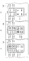
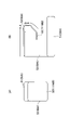
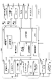
- FIG. 10 It is a figure which shows the interior of the vehicle 10 equipped with the input device of an embodiment. It is a figure which shows the in-vehicle device including the input device 100 of an embodiment. It is a figure which shows the operation part 110 at the time of a normal time and an emergency situation. It is a figure which shows the simulated image displayed on HUD140B. It is a figure which shows the display of HUD140B. It is a figure which shows the display of HUD140B. The display of the HUD140B in the first input mode and the second input mode is shown. It is a flowchart which shows the process which the control unit 120 executes to set the input mode of the operation unit 110.
- FIG. 1 is a diagram showing the interior of a vehicle 10 equipped with the input device of the embodiment.
- FIG. 1 shows a dashboard 11, a center console 12, a windshield (front window) 13, a door panel 14, and the like.
- An operation unit 110 is provided on the center console 12 and the door panel 14, and two cameras 140A are arranged on the ceiling inside the vehicle 10.
- the windshield 13 is provided with a HUD (Head Up Display) 140B
- the dashboard 11 is provided with a display 140C.
- the display 140C is, for example, a display device using an LCD (Liquid Crystal Display), an OLED (Organic Light Emitting Diode), or the like.
- the HUD 140B and the display 140C can display data related to various in-vehicle devices such as a power window switch, a door lock switch, a navigation system, an air conditioner, and audio, in addition to data related to the running state of the vehicle 10.
- the two cameras 140A can capture moving images and still images around the two operation units 110 from above, respectively.
- the operation unit 110 can operate the power window and / or the door lock, and can also operate the power window such as an air conditioner (air conditioner) and audio, and the in-vehicle device other than the door lock.
- the windows that can be operated as power windows are, for example, four side windows arranged in FR (front right), FL (front left), RR (rear right), and RL (rear left) of the vehicle 10.
- FIG. 2 is a diagram showing an in-vehicle device including the input device 100 of the embodiment. Hereinafter, it is assumed that the user operates the input device 100. The user is a user of the vehicle 10, typically a occupant. FIG. 2 shows some of the in-vehicle devices of the vehicle 10 related to the input device 100.
- the input device 100 includes an operation unit 110, a control unit 120, a submersion sensor 130, and a relay device 135.
- the operation unit 110 includes a touch pad 111, an LED (Light Emitting Diode) 112, and a push button switch 113.
- the operation unit 110 is an input device for inputting an operation for the user of the vehicle 10 to operate the in-vehicle device, and receives the operation input of the user.
- the control unit 120 controls the in-vehicle device according to the operation input to the operation unit 110.
- Some in-vehicle devices related to the input device 100 include a camera 140A, a HUD140B, a display 140C, an audio controller 150A, an air conditioning controller 150B, and a controller 150C. Further, some in-vehicle devices related to the input device 100 further include a power window motor 160A, a door lock actuator 160B, and a battery 170.
- the operation unit 110 and the camera 140A are shown one by one, but actually there are two each. Further, in the present embodiment, a configuration including two sets including one operation unit 110 and one camera 140A will be described, but two or more operation units 110 are combined into one camera 140A by using a wide-angle lens or the like. It may be configured to shoot with. Further, the configuration may include three or more sets including one operation unit 110 and one camera 140A.
- the audio controller 150A and the air conditioner controller 150B are control devices that control the audio and the air conditioner of the vehicle 10, respectively.
- the audio controller 150A and the control unit 120 are connected by an in-vehicle LAN (Local Area Network).
- the air conditioning controller 150B and the control unit 120 are connected by an in-vehicle LAN.
- the controller 150C is a control device that controls various in-vehicle devices other than audio and air conditioner.
- the controller 150C and the control unit 120 are connected by an in-vehicle LAN.
- the power window motor 160A is a motor that opens and closes the side window
- the door lock actuator 160B is a drive unit that locks and unlocks the door lock mechanism.
- the battery 170 is a power source that supplies electric power to an in-vehicle device mounted on the vehicle 10.
- the operation unit 110 includes a plurality of touch switches or touch pads.
- the operation unit 110 includes a touch pad 111 that is capacitively coupled to generate a detection signal when an object having a large capacitance approaches.
- the operation unit 110 has an illumination unit.
- the illuminated portion is provided as a part of a panel member having an illuminated function.
- the panel member is a two-color molded body using a translucent resin and a non-transparent resin.
- the panel member and the illuminated portion will be briefly described, and the detailed configuration will be described later with reference to FIG.
- the illumination unit is provided on the surface of the panel member, and transmits the light output from the LED 112 as light representing the shape of a symbol such as a specific mark or character, or light representing a shape other than the shape of the symbol.
- the illuminated portion is lit in the shape of the symbol or in a shape other than the shape of the symbol.
- the symbol is, for example, a character, a number, a symbol, a diagram, a mark, etc. having a predetermined meaning, and here, the function possessed by the operation target (power window, air conditioner, audio, etc.) operated by the operation unit 110.
- the shape other than the shape of the symbol is a shape having no predetermined meaning like the symbol, for example, a shape such as a circle or a quadrangle that transmits the light of the LED 112 as it is, or a circular or rectangular ring surrounding the symbol. It has a forehead-like shape.
- the shape of the illuminated portion may be any shape other than the shape representing such a symbol or the shape of the symbol, and the light transmitted through the illuminated portion is the shape of the symbol or the light representing the shape other than the shape of the symbol. In this way, the panel member having the illuminated portion lights up in a shape other than the shape of the symbol or the shape of the symbol.
- the touch pad 111 has a detection electrode that generates a detection signal that can identify the area where the operation has been performed or can specify the position within the area.
- the touch pad 111 described in this embodiment has a capacitance coupling type detection electrode. When the user brings his / her finger close to the touchpad 111, or when the user touches the touchpad 111 with his / her finger, the touchpad 111 generates a detection signal and transmits the detection signal to the control unit 120. do.
- the touch pad 111 is described as having a capacitance coupling type detection electrode, but the detection electrode has a detection electrode that generates a detection signal capable of determining the position where the operation is performed.
- the detection method is not limited to the capacitance coupling method.
- the detection electrode may be a resistance detection type detection electrode.
- the touch pad 111 may have a configuration in which a plurality of load sensors are arranged on the outer peripheral portion and the position where the operation is performed can be determined based on the detection signal from the load sensor.
- the touch pad 111 is an input unit of the operation unit 110, and is connected to the power window motor 160A and the door lock actuator 160B via the control unit 120 as shown in FIG. Further, the touch pad 111 is connected to the audio controller 150A, the air conditioning controller 150B, and the controller 150C via the control unit 120 and the in-vehicle LAN. The touch pad 111 can be switched between a plurality of input modes, which will be described in detail later, by the control unit 120.
- the input mode of the operation unit 110 may include at least a first input mode and a second input mode, and may include an input mode other than the first input mode and the second input mode, but here, the first The input mode and the second input mode will be described.
- the in-vehicle device that can be operated differs between the first input mode and the second input mode.
- the first input mode is an input mode that enables input for operating at least the power window motor 160A and the door lock actuator 160B, and the power window and / or the door can be input by operating the touch pad 111.
- This is an input mode that enables lock operation.
- An in-vehicle device including at least a power window motor 160A and a door lock actuator 160B that can be operated in the first input mode is an example of the first device. In the following, a mode in which the power window motor 160A and the door lock actuator 160B are operated in the first input mode will be described.
- the second input mode is an input mode that enables input for operating the audio controller 150A, the air conditioner controller 150B, or the controller 150C, and operates the audio, the air conditioner (air conditioner), or other in-vehicle device. Is a possible input mode.
- the second input mode has a plurality of types of input modes according to the in-vehicle device.
- An audio, air conditioner (air conditioner), or other in-vehicle device that can be operated in the second input mode is an example of a second device other than the first device.
- the input mode of the operation unit 110 is switched to the first input mode or the second input mode based on the operation input to the operation unit 110 of the user.
- the operation unit 110 can operate various in-vehicle devices in a plurality of input modes.
- the input mode of the operation unit 110 is forcibly set to the first input mode. This is to enable the operation of the power window and / or the door lock, and to enable the user to escape from the vehicle by operating these. The details will be described later with reference to FIGS. 8 and 9.
- the emergency situation of the vehicle 10 is a state in which the user of the vehicle 10 needs to be rescued, and here, the control of the input device 100 when the vehicle 10 is submerged, which is an example of the emergency situation, will be described.
- the normal time means a time when an emergency situation of the vehicle 10 has not occurred.
- the input device 100 can also respond to an emergency situation other than submersion, and the details thereof will be described later with reference to FIGS. 15 and 16.
- the illuminated unit of the operation unit 110 is highlighted and lit. This is to make the portion of the operation unit 110 that functions as the power window switch and the door lock switch stand out in the first input mode. By doing so, even if it is difficult for the user to make a calm judgment, it is possible to increase the possibility that the operation for securing the escape exit can be performed quickly and appropriately.
- the LED 112 is an example of a light source that outputs light for lighting the illuminated unit of the operation unit 110, and is provided on the back side of a plurality of illuminated units included in the operation unit 110.
- the shape of the illuminated portion illuminated by the LED 112 is not limited to the shape of a symbol such as a character or a symbol, and may have a shape other than the shape of the symbol.
- the object illuminated by the LED 112 is an indicator lamp, an edge portion of regions 111A to 111E assigned to the touch pad 111 described in detail later, and a frame-shaped light guide body provided along the edge portion. May be good. These details will be described later with reference to FIG.
- the input device 100 when the vehicle 10 is submerged, provides an illuminated portion provided in a portion that functions as a power window switch and a door lock switch in the first input mode among a plurality of illuminated portions provided in the operation unit 110. Lights up with emphasis. Such emphasis on the illuminated portion is achieved by lighting only the LED 112 corresponding to the illuminated portion provided in the portion where the input device 100 functions as a power window switch and a door lock switch in the first input mode among the plurality of LEDs 112. It will be realized. The details will be described later with reference to FIG.
- the push button switch 113 is provided between the touch pad 111 and the base of the operation unit 110.
- the base of the operation unit 110 is a base portion for attaching the operation unit 110 to the door panel 14, the center console 12, or the like.
- the push button switch 113 changes to a state in which an operation of pressing the surface of the touch pad 111 is performed, the touch pad 111 detects the operation, and the output of the touch pad 111 detects the operation, the push button switch 113 changes from the non-conducting state. It changes to a conductive state.
- the push button switch 113 returns to the original position before being pressed and returns to the non-conducting state.
- the push button switch 113 is provided for the user to perform an operation for determining the operation content performed by the touch pad 111, for example.
- the push button switch 113 may have a function of detecting a transition of the output of the touch pad 111 when a pressing force is applied, and for example, a tact switch, a rubber dome switch, or the like is generated when the push button switch 113 is pressed. Contact points are used.
- the push button switch 113 includes an infrared sensor or the like that can detect a change in the distance at which the output of the touch pad 111 transitions when a push pressure is applied, and the contact is in a non-conducting state and a conducting state based on the change. It may be a detection mechanism that switches between.
- the input device 100 may be configured not to include the push button switch 113. In that case, for example, it may be configured to detect that the confirmation operation has been performed based on the increase in the area of the fingertip or the like that comes into contact with the touch pad 111 when the touch pad 111 is pressed.
- the operation unit 110 When the input operation to the operation unit 110 is performed, the operation unit 110 generates a detection signal, and the detection signal is transmitted to the control unit 120.
- the control unit 120 that has received the detection signal generates a control signal, and the control signal is transmitted to the device provided in the vehicle 10.
- the vehicle device to be operated by the input device 100 operates in response to the input operation to the operation unit 110.
- a relay device 135 is connected to the control unit 120, and when the vehicle 10 is submerged and the control unit 120 becomes inoperable, electric power is supplied from the battery 170 to only a specific LED 112 via the relay device 135. It is turned on.
- the specific LED 112 is an LED 112 corresponding to the illumination unit provided in the portion that functions as the power window switch and the door lock switch in the first input mode among the plurality of illumination units provided in the operation unit 110. This is to emphasize the part that functions as a power window switch and door lock switch when submerged.
- the power window motor 160A and / or the door lock actuator 160B can be input to the operation unit 110 without going through the control unit 120. Will be in a state where it can be operated directly. The details will be described later.
- the control unit 120 includes a main control unit 121, an operation detection unit 122, a mode switching unit 123, an LED control unit 124, a drive control unit 125, an AR (Augmented Reality) control unit 126, and a memory 127.
- the control unit 120 is realized by a computer including a CPU (Central Processing Unit), a RAM (Random Access Memory), a ROM (Read Only Memory), an HDD (Hard Disk Drive), an input / output interface, an internal bus, and the like.
- the main control unit 121, the operation detection unit 122, the mode switching unit 123, the LED control unit 124, the drive control unit 125, and the AR control unit 126 show the function of the program executed by the control unit 120 as a functional block. Is. Further, the memory 127 functionally represents the memory of the control unit 120.
- the main control unit 121 is a processing unit that controls the control processing of the control unit 120, and is other than the processing executed by the operation detection unit 122, the mode switching unit 123, the LED control unit 124, the drive control unit 125, and the AR control unit 126. Executes the processing of.
- the operation detection unit 122 detects the approach of the object to the touch pad 111 based on the output of the touch pad 111, and also detects the operation content based on the coordinates and the like in which the operation input is performed to the touch pad 111.
- the data representing the approach of the object and the operation content detected by the operation detection unit 122 is transmitted to the mode switching unit 123, the LED control unit 124, the drive control unit 125, or the AR control unit 126.
- the mode switching unit 123 sets the input mode of the operation unit 110 to a first input mode and a plurality of input modes among the second input modes. Switch to one of. Further, when the submersion sensor 130 detects the submersion of the vehicle 10, the mode switching unit 123 forcibly switches the input mode to the first input mode.
- the LED control unit 124 controls lighting of a plurality of LEDs 112 according to the first input mode or the second input mode.
- the LED control unit 124 is set to the operation unit 110. Turn on all the illuminated parts of the above with the normal brightness.
- the submersion sensor 130 does not detect the submersion of the vehicle 10 in the first input mode and when the second input mode is set, it is a normal time when an emergency situation does not occur in the vehicle 10.
- the LED control unit 124 functions as a power window switch and a door lock switch in the first input mode of all the illuminated units of the operation unit 110.
- the illumination unit that illuminates the door is turned on, and the illumination unit other than the illumination unit that illuminates the portion that functions as the power window switch and the door lock switch in the first input mode of all the illumination units of the operation unit 110 is turned off.
- the functional parts will be emphasized. The emphasis is to display the part to be emphasized more prominently than the other parts.
- the LED control unit 124 may light the LED 112 in a color different from the normal time. More specifically, another LED 112 having a different emission color may be provided and turned on when submersion is detected.
- the LED control unit 124 may blink the LED 112 when submersion is detected. Further, the LED control unit 124 may light the LED 112 with a higher brightness than usual. Further, at this time, the LED control unit 124 may turn off the LED 112 other than the portion of the operation unit 110 that functions as the power window switch and the door lock switch in the first input mode. All of these are controls performed to highlight and display the parts that function as power window switches and door lock switches in the first input mode.
- the drive control unit 125 drives the power window motor 160A or the door lock actuator 160B when data representing an operation of opening / closing the power window or an operation of locking / unlocking the door lock is transmitted from the operation detection unit 122. As a result, the side window of the vehicle 10 is opened and closed, or the door lock is locked or unlocked according to the operation amount of the touch pad 111.
- the AR control unit 126 controls the simulated image to be displayed on the HUD 140B or the display 140C.
- the AR control unit 126 touches, in a predetermined case, a simulated image representing the operation unit 110 and its peripheral components in the input mode at that time, according to the data representing the operation content transmitted from the operation detection unit 122.
- a simulated image representing a symbol such as a character, a symbol, or a mark representing the type of switch assigned to the pad 111 is superimposed and displayed on the HUD 140B or the display 140C.
- the AR control unit 126 displays the operation unit 110 on the HUD 140B or the display 140C and its peripheral components based on the relationship between the position of the operation unit 110 included in the image captured by the camera 140A and the position of the hand.
- the simulated image representing the hand is superimposed on the simulated image representing.
- the contents displayed on the HUD 140B or the display 140C under the control of the AR control unit 126 will be described later.
- the memory 127 stores programs and data necessary for the operation detection unit 122, the mode switching unit 123, the LED control unit 124, the drive control unit 125, and the AR control unit 126 to execute the control process, data generated by the control process, and the like. Store. Further, the memory 127 can store the contents of the display settings of the HUD 140B or the display 140C set by the user and the contents of the function assignment to the touch pad 111 set by the user.
- the submersion sensor 130 is a sensor that detects that the vehicle 10 has been submerged to a predetermined depth, and data representing the detection result is transmitted to the control unit 120.
- the submersion sensor 130 is an example of an emergency situation detection unit capable of detecting an emergency situation of the vehicle 10.
- the submersion sensor 130 has two electrode pads that are separated from each other. When the two electrode pads are submerged and conduct with each other through water, the submersion detection circuit connected to the two electrode pads detects the submersion of the vehicle 10.
- the submersion sensor 130 is provided at a position lower than the control unit 120 in the vehicle 10 or at a position where the vehicle 10 is submerged before the control unit 120 when the vehicle 10 is submerged.
- the control unit 120 performs control according to the submerged state. Such control will be described later.
- the control unit 120 becomes inoperable. For example, after the submersion sensor 130 detects the submersion of the vehicle 10, the water depth becomes deeper, and when the control unit 120 is submerged, the control unit 120 becomes inoperable.
- the relay device 135 is an example of a switching circuit, and is inserted in series with a power supply line 180 that directly connects the battery 170, the power window motor 160A, and the door lock actuator 160B via the touch pad 111.
- the power line is realized by a power cable.
- the relay device 135 is provided between the battery 170 and the touch pad 111.
- the symbol + B shown on the power supply line 180 on the upstream side of the relay device 135 indicates the power supply from the positive terminal of the battery 170.
- the relay device 135 detects the potential of the predetermined portion of the control unit 120, and when the control unit 120 is operable, the potential of the predetermined portion is higher than the threshold value, so that the relay device 135 becomes a non-conducting state.
- the power supply line 180 between the battery 170 and the touch pad 111 is in the non-conducting state.
- the in-vehicle device can be operated via the control unit 120 by the operation input to the touch pad 111, and even if the touch pad 111 is operated, the power window motor 160A and the door lock actuator 160B are operated via the power supply line 180. Is not supplied with power.
- the relay device 135 switches to the conduction state and conducts the battery 170 and the touch pad 111.
- the control unit 120 cannot drive the power window motor 160A and the door lock actuator 160B.
- the relay device 135 switches to the conductive state, if the touch pad 111 is operated, power is supplied to the power window motor 160A and the door lock actuator 160B via the power supply line 180.
- the relay device 135 is connected to the LED 112 by the power supply line 180A, and when the relay device 135 is switched to the conduction state, power is supplied from the battery 170 to the LED 112.
- the LED 112 is turned on without going through the control unit 120, and the power window switch and the door lock are performed in the first input mode of the operation unit 110.
- the portion that functions as a switch can be turned on, and the power window motor 160A and / or the door lock actuator 160B can be directly operated by the touch pad 111.
- the LED 112 lights up, so that the user of the vehicle 10 can visually recognize the portion of the operation unit 110 that functions as a power window switch and a door lock switch in the first input mode. Can be recognized by. Therefore, even if the vehicle 10 is submerged and the control unit 120 becomes inoperable, the user visually recognizes the portion of the operation unit 110 that functions as the power window switch and the door lock switch in the first input mode.
- the side window can be opened and the door lock can be unlocked by operating the door lock.
- FIG. 3 is a diagram showing an operation unit 110 during normal times and when an emergency occurs.
- FIG. 3A shows a normal operation unit 110.
- the operation unit 110 has a housing 110A and a touch pad 111.
- the housing 110A is made of resin as an example, and is manufactured by two-color molding.
- the touch pad 111 is housed inside the housing 110A.
- Areas 111A to 111E allocated to the touch pad 111 in a plan view are provided on the surface of the operation unit 110.
- the areas 111A to 111E are areas where the operation input can be independently detected by the touch pad 111.
- an LED 112 and a push button switch 113 are provided on the back side of the regions 111A to 111E inside the housing 110A.
- the edges of the regions 111A to 111E are provided with an uneven shape formed on the housing 110A by the molding technique.
- the housing 110A is configured so that each of the regions 111A to 111E can visually or tactilely determine the boundary with the other adjacent regions.
- an illuminated portion 111Ab having the shape of a symbol indicating an upward arrow indicating that the side window is closed, and an illuminated portion having a symbol shape indicating an downward arrow indicating opening the side window.
- 111Bb and 111Bb are provided respectively.
- the area 111C is provided with an illuminated unit 111Cb having the shape of a symbol representing a character for switching the lock / unlock (UnLock) of the door lock, and the area 111D is provided with a character indicating that the input mode of the operation unit 110 is switched.
- An illumination unit 111Db having the shape of a symbol representing (Mode) is provided.
- the illuminated units 111Bb and 111Cb are examples of a part of the touch pad illuminated in the first illuminated state. Further, the illuminated units 111Bb and 111Cb are examples of illuminated units arranged at positions overlapping with a part of the touch pad for operating the side window (window) or the door lock of the vehicle in a plan view.
- the area 111E is provided with four illuminated portions 111Eb having the shapes of symbols representing the characters FR (front right), FL (front left), RR (rear right), and RL (rear left) representing the four side windows.
- the illuminated portions 111Ab to 111Eb are integrally molded together with the housing 110A by two-color molding.
- the illuminated portions 111Ab to 111Eb are formed of a transparent resin, and the illuminated portions 111Ab to 111Eb are formed.
- the parts other than the above are molded with a resin that is opaque and does not transmit light.
- One LED 112 is provided on the back side of each of the illuminated portions 111Ab to 111Eb. Therefore, when each LED 112 is turned on, the light transmitted through each of the illuminated portions 111Ab to 111Eb becomes light representing the shape of each symbol. As a result, the illuminated portions 111Ab to 111Eb are each lit according to the shape of the symbol. At this time, the brightness of the illuminated portions 111Ab to 111Eb are all constant, and one of the illuminated portions is not emphasized.
- This illuminated state is an example of a second illuminated state that does not emphasize the illumination of the illuminated portion.
- the operation unit 110 When the operation unit 110 is in the first input mode, by touching the illumination units 111Ab to 111Eb provided in the areas 111A to 111E, the side window can be moved up and down, the lock / unlock (UnLock) can be switched, and the input mode ( Mode) can be switched and FR (front right), FL (front left), RR (rear right), and RL (rear left) side windows can be selected.
- the LED 112 when the LED 112 is not lit, only the outlines of the regions 111A to 111E can be seen, and the shapes of the symbols of the illuminated units 111Ab to 111Eb cannot be seen.
- a simulated image representing a symbol such as a character, a symbol, or a mark representing the type of the switch assigned to the touch pad 111 in the first input mode is displayed on the HUD 140.
- the user can also perform an operation using a simulated image representing the operation unit 110 displayed on the HUD 140.
- the operation unit 110 when the operation unit 110 is in the second input mode, a function different from the function represented by the symbols of the illumination units 111Ab to 111Eb is assigned to the areas 111A to 111E.
- the second input mode is an input mode that enables operation input for operating the audio controller 150A, the air conditioning controller 150B, or the controller 150C
- the audio controller can be touched by touching the areas 111A to 111E.
- the 150A, the air conditioning controller 150B, and the controller 150C can be operated.
- the operation is performed using a simulated image representing the operation unit 110 displayed on the HUD 140.
- the illuminated portions 111Ab to 111Eb can transmit light not only to the symbol but also to the contour portion surrounding the symbol (the contour of the regions 111A to 111D and the four contours surrounding the symbols of FR, FL, RR, and RL).
- the symbols and contours may be illuminated by separate LEDs 112 in each of the illuminated portions 111Ab to 111Eb. In this case, when the operation unit 110 is in the second input mode, the LED 112 corresponding to the symbol may not be turned on, but only the LED 112 corresponding to the contour may be turned on.
- the arrow for moving the side window up and down, the lock / unlock (UnLock), the input mode (Mode), and the symbols of FR, FL, RR, and RL are hidden.
- the illuminated portion provided in the contour portion surrounding the symbol is an example of the illuminated portion that lights up in a shape other than the shape of the symbol.
- FIG. 3B is a diagram showing the illuminated state of the operation unit 110 when the submersion sensor 130 detects the submersion of the vehicle 10.
- the input mode of the operation unit 110 is forcibly switched to the first input mode by the mode switching unit 123.
- the LED control unit 124 has an illuminated unit 111Bb representing an arrow-shaped symbol for lowering the side window, and a lock / unlock symbol for the door lock.
- the illuminated unit 111Cb to be represented is turned on, and the other illuminated units 111Ab, 111Db, and 111Eb are turned off.
- This illuminated state is an example of a first illuminated state that emphasizes the illumination of the illuminated portion.
- the illuminated unit 111Bb and the illuminated unit 111Cb are turned on, and the other illuminated units 111Ab, 111Db, and 111Eb are turned off to emphasize the illumination of the illuminated unit 111Bb and the illuminated unit 111Cb. This is to enable the user to quickly unlock and open the side window by displaying only the part that needs to be operated to secure the escape exit from the vehicle 10 when submerged.
- the illuminated unit 111Bb and the illuminated unit 111Cb are turned on with the same brightness, and the other illuminated units 111Ab are turned on.
- 111Db, 111Eb may be reduced in brightness to dimming, thereby emphasizing the illuminated portion 111Bb and the illuminated portion 111Cb. It suffices that the illuminated unit 111Bb and the illuminated unit 111Cb to be emphasized and displayed are lit with relatively high brightness as compared with the other illuminated units 111Ab, 111Db, and 111Eb.
- the LED control unit 124 is only the LED 112 corresponding to the illumination unit 111Bb and the illumination unit 111Cb. Is turned on so that the LED 112 corresponding to the illuminated units 111Ab, 111Db, 111Eb is not turned on.
- the illumination unit 111Bb and the illumination unit 111Cb are illumination units provided in a portion that functions as a power window switch and a door lock switch in the first input mode.
- the operation unit 110 is forcibly set to the first input mode by the mode switching unit 123, so that the illumination of the illumination unit 111Bb and the illumination unit 111Cb is emphasized. In this state, you will be able to unlock the door lock and open the side window. This is to make the parts that function as power window switches and door lock switches stand out so that they can be operated quickly in the event of an emergency. As a result, even if it is difficult for the user to make a calm judgment, the possibility that the operation for opening the escape exit can be quickly and appropriately performed is improved.
- FR front right
- FL front left
- RR rear right
- RL left
- All four side windows of (later) should be opened.
- the side window on the driver's seat side may be opened by pressing the illuminated portion 111Bb, but since there is a possibility that the occupant may be in a seat other than the driver's seat, an escape exit is secured. It is preferable to open all side windows to do this.
- a switch for opening a side window to the user of the vehicle 10 in an emergency such as submersion.
- 111Bb the switch for unlocking the door lock (illuminating unit 111Cb) can be made to stand out.
- the switch to be operated is illuminated and conspicuous, so that it is possible to prevent accidental operation of other parts.
- the display shown in FIG. 3B is performed by controlling the LED control unit 124 to light the LED 112 corresponding to the illumination units 111Bb and 111Cb when the control unit 120 is operable. Even if the unit 120 becomes inoperable, the state in which the LED 112 corresponding to the illuminated units 111Bb and 111Cb is lit is maintained.
- the relay device 135 When the control unit 120 becomes inoperable, the relay device 135 operates to turn on only the LED 112 corresponding to the illumination units 111Bb and 111Cb without going through the control unit 120, and the power window motor is directly operated by the touch pad 111.
- the 160A and the door lock actuator 160B can be driven. Therefore, even if the water depth becomes deep and the control unit 120 becomes inoperable when submerged, the display of the operation unit 110 shown in FIG. 3B can be maintained, and the side window can be opened and closed to unlock the door. It can maintain a lockable state.
- the switch for opening the side window (illuminating unit 111Bb) and the switch for unlocking the door lock (illuminating unit 111Cb) stand out, and the power window motor 160A and the door are conspicuous. This is to ensure that the lock actuator 160B can be driven so that the user of the vehicle 10 can secure an escape exit even when the control unit 120 is submerged to the extent that it becomes inoperable.
- the input device 100 may include an LED that is lit only in the second input mode, in addition to the plurality of LEDs 112 described here. Such an LED may be provided at a position different from the position where the LED 112 is provided in the input device 100, and may output light to an illuminated portion other than the illuminated portions 111Ab to 111Eb.
- the operation unit 110 may include a configuration capable of emphasizing and lighting an arbitrary illumination unit, and may include, for example, a printing film and a light source that can be used instead of the LED 112. Further, the operation unit 110 may be a display mechanism including a liquid crystal display, an organic EL display, a micro LED display, and the like. In these cases, the liquid crystal display, the organic EL display, and the micro LED display become the illumination unit.
- the illuminated portions 111Bb and 111Cb are an example of an illuminated portion arranged at a position where they overlap with a part of the touch pad for operating the side window (window) or the door lock of the vehicle in a plan view.
- the illumination units 111Bb and 111Cb may be combined with at least one touch switch for operating the side window (window) or door lock of the vehicle. This is an example of an illuminated unit arranged at an overlapping position in a plan view.
- FIG. 4 is a diagram showing a simulated image displayed on the HUD140B.
- the display of the HUD 140B will be described as an example, but the same applies to the display of the display 140C.
- FIG. 4A shows a display example of the HUD 140B when the operation unit 110 is normally set to the first input mode and the hand H approaches the operation unit 110.
- the simulated images 111a, 111Aa to 111Ea, and 111Aaa to 111Eaa are displayed on the HUD140B.
- the simulated images 111a, 111Aa to 111Ea, and 111Aaa to 111Eaa are configured by a graphical user interface (GUI).
- GUI graphical user interface
- the simulated image 111a is a simulated image representing the operation unit 110 (see FIG. 3A).
- the simulated images 111Aa to 111Ea are simulated images representing the regions 111A to 111E (see FIG. 3A).
- the simulated images 111Aaa to 111Eaa are simulated images showing the functions assigned to the regions 111A to 111E of the operation unit 110 in the first input mode. Therefore, in the simulated images 111Aaa to 111Daa, an upward arrow indicating that the side window is closed, a downward arrow indicating that the side window is opened, and a character for switching the lock / unlock (UnLock) of the door lock, respectively.
- the simulated image 111Eaa represents the characters FR, FL, RR, and RL representing the four side windows, and the outline of the quadrangle surrounding the characters FR, FL, RR, and RL.
- the simulated images 111Aaa to 111Daa are displayed superimposed on the simulated images 111Aa to 111Ea.
- the first input mode is an input mode for operating the opening / closing of the side window and the switching of the door lock
- the characters Door Lock and Power Window are displayed on the upper side of the simulated image 111a.
- a simulated image Ha representing the hand H is displayed on the HUD140B.
- the simulated image Ha does not overlap with the simulated images 111a, 111Aa to 111Ea, and 111Aaa to 111Eaa. This is because the actual position of the hand H has not reached the operation unit 110.
- the display positions of the simulated images 111a of the operation unit 110, the simulated images 111Aa to 111Ea of the areas 111A to 111E, and the simulated images 111Aaa to 111Eaa of the symbols are fixed in the image displayed by the HUD140B, but the user's hand.
- the position of the simulated image Ha of H is updated in real time based on the position of the hand H captured by the camera 140A.
- the user can grasp the relative positional relationship between his / her hand H and the operation unit 110 while looking at the display of the HUD140B.
- the user who is driving the vehicle can determine the relative positional relationship between his / her hand H and the operation unit 110 only by looking at the display content of the HUD 140B. Since the user does not have to look down to the operation unit 110, it is possible to improve both the accuracy of the input operation by the user and the safety of driving.
- the simulated images 111a, 111Aa to 111Ea, 111Aaa to 111Eaa, and Ha are used in order to reduce the calculation load of the AR control unit 126. However, if the processing speed of the AR control unit 126 is sufficiently high, the images of the actual operation unit 110 and the hand H captured by the camera 140A may be displayed on the HUD 140B. Further, the simulated images 111a, 111Aa to 111Ea, and 111Aaa to 111Eaa may be superimposed and displayed on the images of the actual operation unit 110 and the hand H.
- the control unit 120 detects the approach of the hand H to the touch pad 111 based on the output of the touch pad 111. Further, the control unit 120 detects the approach of the hand H to the operation unit 110 by using the image captured by the camera 140A. As an example, when the image of the hand H does not enter the field of view of the camera 140A, the control unit 120 may detect the approach of the hand H to the touch pad 111 based on the output of the touch pad 111. Further, when the image captured by the camera 140A includes the image of the hand H, the control unit 120 may perform image processing to detect the relative position between the hand H and the operation unit 110. When detecting the relative position between the hand H and the operation unit 110 in the image processing, the positional relationship between the hand H and the operation unit 110 may be detected by using the output of the touch pad 111. Such control may be performed by the operation detection unit 122.
- the AR control unit 126 controls the HUD 140B to form simulated images 111a, 111Aa to 111Ea, 111Aaa to 111Eaa of the operation unit 110 and its surrounding images. , A simulated image Ha representing the hand H is displayed.
- the AR control unit 126 changes the simulated image Ha of the hand H to a transparent display. Then, the AR control unit 126 simulates the simulated images 111Aa to 111Ea of the regions 111A to 111E and the simulated images 111Aaa to 111Eaa such as characters, symbols, or marks representing the functions assigned to the regions 111A to 111E, respectively. It is displayed superimposed on Ha. With this configuration, the user can easily grasp the position to be operated.
- the simulated images 111Aa to 111Ea of the areas 111A to 111E the simulated image 111Aaa representing the symbol indicating closing the side window (upward arrow), and the simulated image representing the symbol indicating opening the side window (downward arrow).
- 111Baa simulated image 111Caa representing characters indicating to switch the lock / unlock (UnLock) of the door lock
- simulated image 111Daa representing the characters indicating switching the input mode of the operation unit 110
- characters representing the side window characters representing the side window.
- the simulated image 111Eaa representing the characters of FR, FL, RR, and RL is an example of an interface imitating the operation unit 110.
- FIG. 4B shows the display of the HUD 140B when the vehicle 10 is submerged.
- the input mode of the operation unit 110 is forcibly set to the first input mode, and only the illuminated units 111Bb and 111Cb are illuminated to the first illuminated state (see FIG. 3B).
- the display of the HUD 140B displays simulated images 111Aa to 111Ea and 111Aaa to 111Eaa relating to the opening / closing of the side window and the switching of the door lock corresponding to the first input mode.
- the downward arrow of the simulated image 111Baa and the Lock / UnLock characters of the simulated image 111Caa can be switched to a bold display state.
- displaying the downward arrow of the simulated image 111Baa and the characters Lock / UnLock of the simulated image 111Caa in bold is an example of highlighting in the HUD140B.
- the emphasis means that the portion to be emphasized is displayed more conspicuously than the other portions.
- the control unit 120 can operate even if the vehicle 10 is submerged. During that time, the user can perform an operation for opening the side window and / or an operation for unlocking the door lock while watching the display of the HUD140B. Since the user can operate the side window or door lock while looking at the display of HUD140B, it is possible to prepare for escape without looking down to the operation unit 110 in the event of an emergency such as submersion. can. This is especially effective when you cannot look down for some reason.
- the operation unit 110 switches between the illuminated unit 111Bb in the shape of a symbol (downward arrow) indicating that the side window can be opened only when the door is submerged, and the lock / unlock (UnLock) of the door lock.
- the form of emphasizing the illuminated portion 111Cb in the shape of the symbol representing the above has been described.
- the operation unit 110 may be configured to emphasize and light only the illumination unit 111Bb and the illumination unit 111Cb not only when submerged in water but also in a normal time. Then, in this case, all of the simulated images 111a, 111Aa to 111Ea, and 111Aaa to 111Eaa may be displayed on the HUD140B.
- the user indicates that the area 111B in which the arrow for opening the side window is highlighted and the door lock are locked / unlocked (UnLock) while the operation unit 110 is repeatedly used in normal times. It becomes easy to memorize the operation position with the area 111C in which the character is highlighted. If the position that needs to be operated to escape from the vehicle 10 is memorized, the user can unlock the door lock or the side window even when the vehicle 10 is submerged and it is difficult to make a calm judgment. There is a high possibility that the operation to open the door can be performed. As a result, it is possible to provide a situation in which the user can easily escape from the vehicle 10.
- FIG 5 and 6 are diagrams showing the display of HUD140B.
- the AR control unit 126 reflects the positional relationship between the operation unit 110 and the hand H included in the image captured by the camera 140 in the positional relationship between the simulated images 111a and Ha in the display of the HUD 140B. That is, the HUD140B moves the position of the simulated image Ha in real time according to the change in the actual position of the hand H.
- FIG. 5A shows simulated images 111Aa to 111Ea imitating the regions 111A to 111E allocated to the touchpad 111 in a plan view in a state where the hand H is not close to the touchpad 111 in a normal state.
- the simulated images 111Aa to 111Ea display simulated images 111Aaa to 111Eaa (see FIG. 4A) such as arrows indicating the functions assigned to the regions 111A to 111E. Not done.
- the simulated images 111Aa to 111Ea displayed on the HUD140B represent the entire area 111A to 111E of the operation unit 110, but the display of the HUD140B must be inconsistent with the areas 111A to 111E of the operation unit 110. For example, a part of the regions 111A to 111E may be missing by enlarging.
- FIG. 5B shows simulated images 111Aa to 111Ea and 111Aaa to 111Eaa and simulated images Ha imitating the hand H when the operation unit 110 is set to the first input mode in the normal state.
- the control unit 120 opens the side window, which is a symbol (upward arrow) indicating that the side window is closed, in the simulated images 111Aa to 111Ea, as shown in FIG. 5 (B).
- a symbol (down arrow) indicating that, a character indicating that the door lock is locked / unlocked (UnLock), a character indicating that the input mode of the operation unit 110 is switched (Mode), and a side window.
- the simulated images 111Aaa to 111Eaa of the characters FR, FL, RR, and RL are superimposed and displayed.
- the display content of the HUD140B shown in FIG. 5B is the same as the display of the HUD140B shown in FIG. 4A.
- the control unit 120 locks / unlocks the simulated image 111Aaa (upward arrow) indicating that the side window displayed superimposed on the simulated image 111Aa is closed, and the locked / unlocked image 111Ca superimposed on the simulated image 111Ca.
- the simulated image 111Caa representing the characters of UnLock) is highlighted and displayed.
- the upward arrow of the simulated image 111Aaa and the characters of the simulated image 111Caa are emphasized by displaying them in bold.
- FIG. 5C shows a state in which the front right (FR) side window, which is the side window of the driver's seat, is selected and the simulated image 111Fa is displayed.
- FR front right
- FIG. 5C shows a state in which the front right (FR) side window, which is the side window of the driver's seat, is selected and the simulated image 111Fa is displayed.
- FR front right
- FIG. 5C shows a state in which the front right (FR) side window, which is the side window of the driver's seat, is selected and the simulated image 111Fa is displayed.
- FR front right
- the simulated image 111Ea representing the characters FR, FL, RR, and RL is not displayed in the simulated image 111Ea (see FIG. 5B). .. Since the side window has been selected, the simulated image 111Eaa representing the characters FR, FL, RR, and RL is hidden.
- a simulated image including the characters FL, RR, and RL may be displayed as the simulated image 111F instead of the characters of Driver.
- the simulated image Ha of the hand H is translucent, and the simulated images 111Aa to 111Ea, 111Aaa to 111Daa, and 111Fa overlapping with the simulated image Ha of the hand H are displayed so as to appear faint. .. This is to make it possible to confirm the simulated images 111Aa to 111Ea, 111Aaa to 111Daa, and 111Fa that overlap with the simulated image Ha of the hand H.
- the outline of the portion where the simulated images 111Aa to 111Ea are displayed lightly is shown by a broken line.
- the upward arrow of the simulated image 111Aaa and the characters of the simulated image 111Caa are emphasized by making them thicker than those in FIG. 5B, but the characters may be blinked or the characters may be blinked.
- the size may be larger than the letters shown in FIG. 5 (B).
- the color may be changed to a color different from the color of the characters shown in FIG. 5B, or the brightness may be improved.
- the thickness of the characters shown in FIG. 5B may be changed so as to pulsate, or may be displayed by enclosing characters surrounding the portion to be emphasized with a frame. Highlighting can be performed by such various methods. Further, the highlighting of the simulated images by such various methods may be performed on the simulated images 111Baa and 111Caa when the vehicle 10 is submerged as shown in FIG. 4 (B).
- the control unit 120 locks the door lock displayed on top of the simulated image 111Ca displayed on the HUD 140B, as shown in FIG. 6 (A).
- the simulated image 111Caa of characters indicating switching between (Lock) and unlock (UnLock) is highlighted and displayed.
- the apparatus 120 is displayed superimposed on the simulated image 111Aa located on the fingertip of the simulated image Ha, as shown in FIG. 6B.
- the simulated image 111Aaa of the symbol (upward arrow) indicating that the side window is closed is highlighted and displayed.
- change the color improve the brightness, change the thickness of the lines that make up the characters so that they pulsate, or display a frame around the part to be emphasized, etc.
- the display may be emphasized by.
- FIGS. 6A and 6B the side window on the front right (FR), which is the side window of the driver's seat, is selected and the simulated image 111F is displayed, as in FIG. 5C.
- the simulated image 111Ea (see FIG. 5B) representing the characters FR, FL, RR, and RL is not displayed on the simulated image 111Ea.
- FIG. 7 shows the display of the HUD 140B in the first input mode and the second input mode.
- FIG. 7A shows the display of the HUD 140B when the first input mode in which the power window and the door lock can be operated is selected.
- a simulated image 111a showing the operation unit 110 (see FIG. 3A) is displayed on the HUD 140B.
- the characters Door Lock and Power Window are displayed on the upper part of the simulated image 111a.
- simulated images 111Aa to 111Ea imitating the areas 111A to 111E are displayed below the characters of Door Lock and Power Window.
- simulated images 111Aaa to 111Eaa such as characters representing the functions assigned to the regions 111A to 111E are superimposed and displayed. That is, the simulated image 111Aa displays the simulated image 111Aaa of the symbol (upward arrow) indicating that the side window is closed, and the simulated image 111Ba displays the simulated image 111Baa of the symbol (downward arrow) indicating that the side window is opened. Is displayed.
- the simulated image 111Ca displays a simulated image 111Caa of characters indicating switching between locking (Lock) and unlocking (UnLock), and the simulated image 111Da displays a simulated image 111Daa of characters indicating mode selection (Mode).
- a simulated image 111Eaa representing characters (FR, FL, RR, RL) indicating the position of a seat in the vehicle is displayed.
- Such a display of the HUB 140B is equivalent to a display in which the simulated image Ha of the hand H is removed from the display shown in FIG. 4 (B).
- FIG. 7B shows the display of HUD140B in the air conditioning input mode of the second input mode.
- a simulated image 111a showing the operation unit 110 (see FIG. 3A) is displayed on the HUB 140B.
- the characters of Air Conditioner are displayed in the upper portion of the simulated image 111a, and the simulated images (111Aa to 111Ea) imitating the regions (111A to 111E) are displayed below the characters of Air Conditioner.
- the simulated image 111Aa displays a simulated image 111Aab of a symbol (upward arrow) indicating that the set temperature is raised
- the simulated image 111Ba displays a simulated image 111Bab of a symbol (downward arrow) indicating that the set temperature is lowered.
- the simulated image 111Ca displays a simulated image 111Cab of characters indicating an automatic mode (Auto)
- the simulated image 111Da displays a simulated image 111Dab indicating a mode selection
- four simulated images 111Eab are displayed in the simulated image 111Ea.
- the four simulated images 111Eab are a simulated image for mode selection for setting the wind direction and defroster shown in the upper right, a simulated image for mode selection for setting the fan air volume shown in the lower right, and a mode selection for setting the temperature shown in the upper left. It is a simulated image of, and a simulated image for mode selection for setting the internal air circulation shown in the lower left.
- FIG. 7C shows the display of the HUD 140B in the audio input mode of the second input modes.
- a simulated image 111a showing the operation unit 110 (see FIG. 3A) is displayed on the HUB 140B.
- the characters of Audio are displayed in the upper portion of the simulated image 111a, and the simulated images 111Aa to 111Ea are displayed below the characters of Audio.
- the simulated image 111Aa displays a simulated image 111Aac of characters indicating radio channel selection (Tune), and the simulated image 111Ba displays a simulated image 111Bac of a symbol representing mute.
- the simulated image 111Ca displays the simulated character 111Cac indicating the input source selection (Source) of the audio data
- the simulated image 111Da displays the simulated image 111Dac of the character indicating the mode selection (Mode).
- four simulated images 111Eac are displayed on the simulated image 111Ea.
- the four simulated images 111Eac are a simulated image of the reproduction start mark on the upper right side, a fast-forwarding simulated image on the lower right, a stop simulated image on the upper left, and a rewinding simulated image on the lower left.
- the display content of the HUD140B in the audio input mode described in this embodiment is only an example, and various changes can be made.
- the simulated images 111Aac to 111Eac displayed on the simulated images 111Aa to 111Ea
- the simulated images 111Aac to 111Eac may be configured to be freely adjustable according to the intention of the user.
- the audio function assigned to the areas 111A to 111E of the operation unit 110 may be changed in the same manner.
- the display content of the HUD 140B is switched according to the input mode selected by the operation input to the operation unit 110. Further, although the simulated image Ha of the hand H is omitted in FIGS. 7 (A) to 7 (C), it is the same as in FIGS. 5 (B), 5 (C), 6 (A), and 6 (C). In addition, the position of the simulated image Ha of the hand H displayed on the HUD 140B is changed in real time according to the position of the hand H with respect to the actual operation unit 110 imaged by the camera 140. The display content of such HUD140B is controlled by the AR control unit 126.
- FIG. 8 is a flowchart showing a process executed by the control unit 120 to set the input mode of the operation unit 110.
- FIG. 9 is a flowchart showing a process in which the control unit 120 switches between the input mode and the display when an emergency occurs.
- the mode switching unit 123 switches the input mode of the operation unit 110
- the LED control unit 124 switches the illumination state of the operation unit 110
- the AR control unit 126 switches the display of the HUB 140B.
- control unit 120 When the process starts in FIG. 8, the control unit 120 performs the following process.
- the mode switching unit 123 determines whether or not an emergency detection signal has been received (step S0). When the submersion sensor 130 detects that the vehicle 10 is submerged, it generates an emergency detection signal and transmits it to the control unit 120. Therefore, the mode switching unit 123 monitors whether or not the emergency detection signal has been received. ..
- the mode switching unit 123 determines that the emergency detection signal has been received (S0: YES)
- the mode switching unit 123 starts processing in the emergency situation shown in FIG.
- the input mode of the operation unit 110 is forcibly switched to the first input mode (step S11).
- the operation unit 110 can perform an operation of opening the side window and an operation of unlocking the door lock (UnLock) without the user performing an operation of selecting the first input mode. You will be ready to do it.
- the operation of selecting the input mode is an example of the mode selection operation.
- the LED control unit 124 has an LED 112 corresponding to an illuminated unit 111Bb indicating a downward arrow indicating that the side window can be opened and an illuminated unit 111Cb indicating a character for switching the lock / unlock (UnLock) of the door lock. It lights up and turns off the LED 112 corresponding to the illuminated units 111Ab, 111Db, 111Eb (step S12).
- step S12 when the illuminated units 111Bb and 111Cb are already lit, the LED control unit 124 keeps the illuminated units 111Bb and 111Cb in the lit state.
- the operation unit 110 is in the state shown in FIG. 3B, and is illuminated with the side window serving as an escape exit in an emergency and the position where the door is opened are emphasized. Is clearly shown.
- the AR control unit 126 displays simulated images 111Aa to 111Ea and 111Aaa to 111Eaa relating to opening / closing of the side window and switching of the door lock corresponding to the first input mode, and also displays simulated images.
- the display content of the HUD140B is changed to the display content that emphasizes the downward arrow of 111Baa and the Lock / UnLock character of the simulated image 111Caa (step S13).
- the side window that serves as an escape exit in an emergency and the operation position related to the operation of opening the door are clearly shown on the display of the HUD140B.
- the AR control unit 126 obtains the position of the hand H with respect to the operation unit 110 based on the image captured by the camera 140A, and displays the simulated image Ha of the hand H on the HUD 140B (step S14).
- the control unit 120 determines whether or not a command has been received from the host device (step S15).
- the host device is an ECU (Electronic Control Unit) or the like that controls any device of the vehicle 10.
- ECU Electronic Control Unit
- this ECU returns the control process of the control unit 120 from the process at the time of an emergency to the process at the normal time in other cases. Send a command to.
- the AR control unit 126 causes the AR control unit 126 to repeatedly perform the process of step S14. This is to update the display of the HUD 140B according to the movement of the hand H.
- control unit 120 determines that the command has been received from the host device (S15: YES)
- the control unit 120 advances the flow to step S1 shown in FIG. This is to restore the normal processing.
- the display of the HUD 140B is updated according to the movement of the hand H as long as the control unit 120 can operate.
- the control unit 120 is submerged and becomes inoperable, power is supplied from the battery 170 to the LED 112 corresponding only to the illuminated units 111Bb and 111Cb via the relay device 135, and the illuminated units 111Bb and 111Cb are turned on.
- the power window motor 160A and the door lock actuator 160B can be directly operated by the operation input to the operation unit 110.
- the illuminated units 111Bb and 111Cb of the operation unit 110 are emphasized and held in a lit state, and the power window motor 160A and the door lock actuator 160B are secured in an operable state. This is to enable the user to secure an escape exit.
- step S0 shown in FIG. 8 when it is determined that the mode switching unit 123 has not received the emergency detection signal (S0: NO), and in step S15 shown in FIG. 9, a command is received from the host device ( S15: YES), the control unit 120 starts the normal processing in step S1 or lower.
- the mode switching unit 123 determines whether or not the first input mode is specified for the input mode of the operation unit 110 based on the operation content detected by the operation detection unit 122 (step S1).
- the mode switching unit 123 determines that the first input mode is specified (S1: YES)
- the mode switching unit 123 sets the input mode of the operation unit 110 to the first input mode (step S2).
- the power window and the door lock can be operated via the operation unit 110.
- the mode switching unit 123 determines that the first input mode is specified (S1: YES) in order to set the first input mode from the state in which the input mode of the operation unit 110 is not set.
- the mode switching unit 123 determines whether or not the input mode has been switched based on the operation content detected by the operation detection unit 122 (step S3).
- the mode switching unit 123 determines that the input mode has not been switched (S3: NO)
- it returns the flow to step S2 and sets the input mode of the operation unit 110 to the first input mode (step S2). This is the case where the first input mode has already been set and the mode has not been switched.
- the touch pad 111 keeps the power window and the door lock in an operable state.
- the mode switching unit 123 determines that the input mode has been switched (S3: YES)
- the mode switching unit 123 returns the flow to step S1. This is to determine whether or not the mode has been switched to the first input mode.
- step S1 determines in step S1 that the first input mode is not specified (S1: NO), whether or not the air conditioning input mode among the plurality of input modes included in the second input mode is specified. Is determined (step S4).
- the mode switching unit 123 determines that the air conditioning input mode is specified (S4: YES)
- the mode switching unit 123 sets the input mode of the operation unit 110 to the air conditioning input mode (step S5). This makes it possible to operate the air conditioner via the operation unit 110. If the area 111D of the operation unit 110 is operated during step S5, it will be determined in the next step S6.
- the mode switching unit 123 determines whether or not the input mode has been switched based on the operation content detected by the operation detection unit 122 (step S6).
- the mode switching unit 123 determines that the input mode has not been switched (S6: NO), it returns the flow to step S5 and sets the input mode of the operation unit 110 to the air conditioning input mode (step S2). As a result, the operation unit 110 keeps the air conditioner in an operable state.
- the mode switching unit 123 determines that the input mode has been switched (S6: YES)
- the mode switching unit 123 returns the flow to step S1.
- step S4 determines whether the air conditioning input mode is not specified (S4: No). It determines whether the audio input mode among the plurality of input modes included in the second input mode is specified. Determination (step S7).
- the mode switching unit 123 determines that the audio input mode is specified (S7: YES)
- the mode switching unit 123 sets the input mode of the operation unit 110 to the audio input mode (step S8). This makes it possible to operate the audio via the operation unit 110. If the area 111D of the operation unit 110 is operated during step S8, it will be determined in the next step S9.
- the mode switching unit 123 determines whether or not the input mode has been switched based on the operation content detected by the operation detection unit 122 (step S9).
- the mode switching unit 123 determines that the input mode has not been switched (S8: NO), it returns the flow to step S8 and sets the input mode of the operation unit 110 to the audio input mode (step S8). As a result, the audio can be operated via the operation unit 110.
- step S7 determines in step S7 that the audio input mode is not specified (S7: NO)
- FIG. 10 is a flowchart showing a process executed by the control unit 120 regarding the display of the HUD 140B.
- the control unit 120 performs the following process.
- the processing when the input mode of the operation unit 110 is the first input mode will be described.
- the operation detection unit 122 determines whether or not an object is approaching the operation unit 110 based on the output of the touch pad 111 (step S21).
- the operation detection unit 122 detects whether or not the object is approaching the operation unit 110 by detecting a change in capacitance due to the object approaching the touch pad 111 provided inside the housing 110A of the operation unit 110. To detect.
- the AR control unit 126 turns on the HUD140B and displays simulated images 111a, 111Aa to 111Ea (step S22). That is, the HUB 140B displays the image shown in FIG. 5 (A).
- the operation detection unit 122 determines whether or not the object is the hand H (step S23). The operation detection unit 122 determines whether or not the hand is H based on the image captured by the camera 140A.
- the AR control unit 126 When the operation detection unit 122 determines that the hand is H (S23: YES), the AR control unit 126 represents simulated images 111Aaa to 111Eaa representing the functions corresponding to the input modes selected by the operation input to the operation unit 110. And the simulated image Ha of the hand H is displayed on the HUD140B (step S24). At this time, when the input mode of the operation unit 110 is selected as the first input mode, the AR control unit 126 has FIGS. 4A and 5A depending on the status of the operation input to the operation unit 110. (B) or an image as shown in FIG. 7 (A) is displayed on the HUD140B.
- the AR control unit 126 displays the HUD 140B in FIGS. 7 (B) and 7 depending on the status of the operation input to the operation unit 110.
- An image in which the simulated image Ha of the hand H is added to the image shown in (C) is displayed.
- the AR control unit 126 performs image processing on the image captured by the camera 140A to obtain the positional relationship between the operation unit 110 and the hand H, and reflects it in the position of the simulated image Ha of the hand H.
- the operation detection unit 122 determines whether or not the object has left the operation unit 110 (step S25). The operation detection unit 122 determines whether or not the object has moved away from the operation unit 110 by detecting the change in capacitance.
- step S23 When the operation detection unit 122 determines that the object is not separated from the operation unit 110 (S25: NO), the flow is returned to step S23. As a result, the processes of steps S23 and S24 are performed, and the display contents of the HUD 140B are updated.
- step S25 When the operation detection unit 122 determines in step S25 that the object has left the operation unit 110 (S25: YES), the AR control unit 126 turns off the display of the HUD 140B (step S26).
- the control unit 120 repeatedly executes a series of processes as described above.
- the switch and the door for opening the side window in the operation unit 110 by lighting the LED 112 corresponding to the illumination units 111Bb and 111Cb as shown in FIG. 3 (B).
- the switch for unlocking the lock can be highlighted.
- Such lighting of the LED 112 is performed by the LED control unit 124 when the control unit 120 is operable, and is realized by operating the relay device 135 to light the LED 112 when the control unit 120 becomes inoperable. LED.
- a window other than the side window of the vehicle 10 may be used.
- an input device 100 that can notify the operation position of the window or door lock of the vehicle 10 when the vehicle 10 is submerged. Since the position where the operation for opening the side window is performed and the position where the operation for unlocking the door lock is performed are illuminated, the user can operate intuitively. Therefore, it is possible to improve the possibility that the user can escape from the vehicle 10 in an emergency such as submersion.
- the simulated images 111Baa and 111Caa of the simulated images 111a, 111Aa to 111Ea and 111Aaa to 111Eaa of the HUD140B are displayed in an emphasized state. It is possible to improve the possibility that the user can escape from the vehicle 10 in an emergency such as submersion.
- the control unit 120 controls the LED 112 corresponding to the illumination units 111Bb and 111Cb provided in the portion of the operation unit 110 that functions as a power window switch and / or a door lock switch in the first input mode. If the light is turned on in a color different from the normal time, the illuminated portions 111Bb and 111Cb can be made to stand out by the emphasizing method of lighting in a color different from the normal time. Therefore, it is possible to make it easy for the user to find the switch for opening the side window and the switch for unlocking the door lock in an emergency such as submersion.
- the control unit 120 controls the LED 112 corresponding to the illumination units 111Bb and 111Cb provided in the portion of the operation unit 110 that functions as a power window switch and / or a door lock switch in the first input mode. If is blinking, the illuminated portions 111Bb and 111Cb can be made to stand out by the highlighting method of blinking. Therefore, it is possible to make it easy for the user to find the switch for opening the side window and the switch for unlocking the door lock in an emergency such as submersion.
- the control unit 120 controls the LED 112 corresponding to the illumination units 111Bb and 111Cb provided in the portion of the operation unit 110 that functions as a power window switch and / or a door lock switch in the first input mode.
- the illuminated portions 111Bb and 111Cb are lit with a higher brightness than usual, the illuminated portions 111Bb and 111Cb can be made to stand out by the highlighting method of lighting with a higher brightness. It is possible to make it easy for the user to find the switch for opening the side window and the switch for unlocking the door lock in an emergency such as submersion.
- the LEDs 112 corresponding to the illumination units 111Bb and 111Cb provided in the portion functioning as the power window switch and / or the door lock switch in the first input mode of the operation unit 110 are turned on, and the other LEDs 112 are turned on. If the light is turned off, it can be made to stand out by the emphasis method of turning on only the illuminated portions 111Bb and 111Cb even in the normal state. For this reason, it is possible for the user to easily remember the positions of the switch for opening the side window and the switch for unlocking the door lock from normal times, and when submersion occurs, the side window can be opened. You can make it easier to find the switch to open and the switch to unlock the door lock.
- the simulated image 111Baa representing the symbol (downward arrow) indicating that the side window is opened in the display of the HUD140B, and the locking / unlocking (UnLock) of the door lock can be switched.
- the control unit 120 blinks the simulated image 111Caa representing the characters to be represented, the simulated images 111Baa and 111Caa can be made to stand out by the emphasis method of blinking. Therefore, among the simulated images 111a, 111Aa to 111Ea, and 111Aaa to 111Eaa displayed on the HUD140B in an emergency such as submersion, the position where the operation is necessary to secure the escape exit from the vehicle 10 can be transmitted to the user. It is possible to make it easy for the user to find the switch for opening the side window and the switch for unlocking the door lock.
- the control unit 120 increases the size of the simulated images 111Baa and 111Caa in the display of the HUD 140B when the vehicle 10 is submerged, the simulated images 111Baa and 111Caa can be made conspicuous by a highlighting method called enlarged display. Therefore, among the simulated images 111a, 111Aa to 111Ea, and 111Aaa to 111Eaa displayed on the HUD140B in an emergency such as submersion, the position where the operation is necessary to secure the escape exit from the vehicle 10 can be transmitted to the user. It is possible to make it easy for the user to find the switch for opening the side window and the switch for unlocking the door lock.
- the colors of the simulated images 111Baa and 111Caa are changed, the brightness is improved, the line thicknesses of the simulated images 111Baa and 111Caa are changed over time so as to pulsate, and the simulated images 111Baa are changed.
- the simulated images 111Baa and 111Caa can also be emphasized by displaying the frame surrounding the 111Caa. Even with these emphasizing methods, it is possible to inform the user of the position that needs to be operated to secure the escape exit from the vehicle 10, and the switch for the user to open the side window and the door lock for unlocking. You can make the switch easy to find.
- the contents described above for the display of the HUD 140B can also be applied to the display of the display 140C.
- FIG. 11 is a diagram showing an operation unit of a modified example of the embodiment.
- the operation unit 110M1 may have a configuration having one region 111MA.
- a symbol (downward arrow) indicating that a side window can be opened may be provided in a part of the area 111MA (for example, about 1/4 of the whole area) by two-color molding to have a translucent portion 111MA1 that can be lit. .. Since it has a simple configuration, it can be manufactured at a lower cost, and is suitable for vehicles with a low vehicle price and vehicles with a simplified interior.
- FIG. 11C shows simulated images 110a, 111MAa, 111MBa, 111MCa displayed on the HUD140B in the audio input mode.
- the simulated image 110a is a simulated image representing the housing of the operation unit 110M2
- the simulated images 111MAa, 111MBa, and 111MCa are simulated images representing the regions 111MA, 111MB, and 111MC, respectively.
- a simulated image 111MBaa representing an arrow in the vertical direction is superimposed and displayed on the fingertip of the simulated image Ha of the hand H superimposed on the simulated image 111MBa.
- FIG. 12 is a diagram showing a portion of the region 111MB of the operation unit 110M2 shown in FIG. 11B.
- FIG. 12A shows an extracted portion of the region 111MB of the operation unit 110M2.
- the portion of the region 111MB of the operation unit 110M2 is referred to as a touch pad unit 50.
- the touch pad portion 50 is provided on the surface of the substrate 50A having the lower portion 51, the upper portion 52, and the connection portion 53.
- the touch pad portion 50 is a bendable and flexible touch pad, and as shown in FIG. 12 (B), the touch pad portion 50 is bent and attached over the lower surface, the side surface, and the upper surface of the upper stage portion 52.
- the touch pad portion 50 When the touch pad portion 50 is pushed down while the upper surface of the upper portion 52 is touched by a hand, the input is received by the push button switch 113 (see FIG. 2), and the side window is lowered only while the touch pad portion 50 is pressed. Can be done.
- the side window can be opened to the fully lowered state in the auto mode. be able to.
- the input is accepted by the push button switch 113 (see FIG. 2), and the side is set in the auto mode. You can keep the window fully open.
- FIG. 13 is a diagram showing an operation unit 110M3 of a modified example of the embodiment.
- the operation unit 110M3 has the same regions 111A to 111E as the operation unit 110 (see FIG. 3A) in a plan view. 13 (B) shows the cross section taken along the line AA of FIG. 13 (A), and FIG. 13 (C) shows the cross section taken along the line BB of FIG. 13 (A).
- the operation unit 110M3 has regions 111A to 111E similar to the touch pad 111 shown in FIG. 3B, but as shown in FIG. 13B, a convex portion 111G is provided in the center of the surface of the region 111E. As shown in FIG.
- each region can be determined by tactile sensation, so that the accuracy of input and the safety of operation when the user performs an input operation can be further improved. ..
- FIG. 14 is a diagram showing an example of an image of HUD140B.
- a simulated image showing the operation unit 110M3 (see FIG. 13A) is displayed in the air conditioning input mode, and the regions 111A to 111E, the convex portion 111G, and the concave portion 111H shown in FIG. 13A are displayed.
- the simulated images 111Aa to 111Ea, 111Ga, and 111Ha are displayed.
- a simulated image 111Ia representing a dial mark for adjusting the air volume is superimposed and displayed.
- a simulated image 111Ja representing a mode selection image for setting the wind direction and the defroster is displayed inside the simulated image 111Ha on the upper right.
- the hand H is moved on the operation unit 110 in an attempt to bring the simulated image Ha of the hand H closer to the simulated image 111J while looking at the display of the HUD 140B shown in FIG. 14B, the hand H touches the recess 111H. Therefore, the position of the simulated image 111Ja can be recognized according to the position of the recess 111H.
- FIG. 15 is a diagram showing an input device 100A of a modified example of the embodiment.
- the input device 100A has a configuration in which a collision sensor 190 is added to the input device 100A shown in FIG.
- the collision sensor 190 is a sensor that detects that the vehicle 10 has collided with another object or the like based on the acceleration generated in the vehicle 10, and detects an emergency situation like the submerged sensor 130 that detects submersion when the collision is detected.
- a signal is generated and output to the control unit 120.
- the input device 100A operates by performing processing according to the flow shown in FIGS. 8, 9, and 10.
- the process proceeds from step S0 shown in FIG. 8 to the process shown in FIG. 9, and the processes of steps S11 to S15 are executed.
- the input device 100A When the collision is detected by the collision sensor 190, the input device 100A forcibly switches the input mode of the operation unit 110 to the first input mode in the same manner as when the submersion sensor 130 detects the submersion.
- the input device 100A is selected by the operation input to the operation unit 110 (first input mode and). Set to either one of the second input modes).
- the collision sensor 190 detects that the vehicle has collided, it generates an emergency detection signal and transmits it to the control unit 120. As shown in FIG. 8, the control unit 120 determines whether or not the emergency detection signal has been received (step S0), and determines that the emergency detection signal has been received (S0: YES). , Perform the processing in the emergency shown in FIG.
- the process executed by the input device 100A when the collision is detected by the collision sensor 190 is the same as the process of steps S11 to S15 shown in FIG. 9, and the illuminated unit 111Bb is used to secure an escape exit from the vehicle 10. , Only the LED 112 corresponding to 111Cb is turned on, and the simulated images 111Baa and 111Caa are highlighted and displayed. Thereby, even when the collision is detected by the collision sensor 190, it is possible to provide the input device 100A capable of notifying the operation position of the window or the door lock of the vehicle 10.
- FIG. 16 is a diagram showing a state of the operation unit 110 at the time of a collision of the vehicle 10.
- the illumination unit 111Bb having the shape of a symbol indicating a downward arrow indicating that the side windows of the areas 111B and 111C of the touchpad 111 are opened by turning on the LED 112 by the control unit 120, and the door lock.
- the illumination unit 111Cb which indicates switching between locking (Lock) and unlocking (UnLock), is lit by transmitted light. Other illuminated areas are turned off. Therefore, the part that functions as a switch for opening the side window in the event of a collision of the vehicle 10 and the part that functions as a switch for unlocking the door lock can be emphasized and displayed, and the user can display the part. By visually recognizing and operating it, the side window can be opened and the door lock can be unlocked to escape from the vehicle.
- the simulated images 111Baa and 111Caa are displayed on the HUD140B with emphasis.
- the illumination unit 111Cb for releasing the door lock is turned on and the simulated image 111Caa is emphasized
- the illumination unit 111Bb for the operation of opening the side window is turned on and the simulated image 111Baa is emphasized. It is not necessary, but if the side window can be opened, an escape exit can be secured when it is difficult to open the door.
- the configuration for providing image information to the user mainly using the HUD140B has been described in the present embodiment, the configuration may be such that the display 140C is mainly used to provide the image information. Further, the image information may be provided to the user by using both the HUD 140B and the display 140C.
- an input device 100 that can notify the operation position of the door lock of the vehicle 10 when the vehicle 10 is submerged or collides.
- the submersion sensor 130 operates to perform the same processing as at the time of submersion.
- a sensor capable of detecting an emergency situation other than submersion and collision may be further provided so as to be able to respond to an emergency situation other than submersion and collision.
Landscapes
- Engineering & Computer Science (AREA)
- Mechanical Engineering (AREA)
- Chemical & Material Sciences (AREA)
- Combustion & Propulsion (AREA)
- Transportation (AREA)
- Lock And Its Accessories (AREA)
- Power-Operated Mechanisms For Wings (AREA)
Priority Applications (4)
| Application Number | Priority Date | Filing Date | Title |
|---|---|---|---|
| CN202180064266.0A CN116261533A (zh) | 2020-11-09 | 2021-09-07 | 输入装置 |
| DE112021005889.4T DE112021005889T5 (de) | 2020-11-09 | 2021-09-07 | Eingabeeinrichtung |
| JP2022560656A JP7426504B2 (ja) | 2020-11-09 | 2021-09-07 | 入力装置 |
| US18/306,480 US12280714B2 (en) | 2020-11-09 | 2023-04-25 | Input device |
Applications Claiming Priority (2)
| Application Number | Priority Date | Filing Date | Title |
|---|---|---|---|
| JP2020186765 | 2020-11-09 | ||
| JP2020-186765 | 2020-11-09 |
Related Child Applications (1)
| Application Number | Title | Priority Date | Filing Date |
|---|---|---|---|
| US18/306,480 Continuation US12280714B2 (en) | 2020-11-09 | 2023-04-25 | Input device |
Publications (1)
| Publication Number | Publication Date |
|---|---|
| WO2022097362A1 true WO2022097362A1 (ja) | 2022-05-12 |
Family
ID=81457783
Family Applications (1)
| Application Number | Title | Priority Date | Filing Date |
|---|---|---|---|
| PCT/JP2021/032780 Ceased WO2022097362A1 (ja) | 2020-11-09 | 2021-09-07 | 入力装置 |
Country Status (5)
| Country | Link |
|---|---|
| US (1) | US12280714B2 (https=) |
| JP (1) | JP7426504B2 (https=) |
| CN (1) | CN116261533A (https=) |
| DE (1) | DE112021005889T5 (https=) |
| WO (1) | WO2022097362A1 (https=) |
Cited By (1)
| Publication number | Priority date | Publication date | Assignee | Title |
|---|---|---|---|---|
| JP2024127430A (ja) * | 2023-03-09 | 2024-09-20 | トヨタ自動車株式会社 | 情報処理システム |
Families Citing this family (1)
| Publication number | Priority date | Publication date | Assignee | Title |
|---|---|---|---|---|
| DE102024205507A1 (de) | 2024-06-14 | 2025-12-18 | Robert Bosch Gesellschaft mit beschränkter Haftung | Verfahren und Vorrichtung zur Ansteuerung wenigstens einer Komponente eines Fahrzeugs in Abhängigkeit eines am Fahrzeug anliegenden Wasserspiegels |
Citations (5)
| Publication number | Priority date | Publication date | Assignee | Title |
|---|---|---|---|---|
| JP2002070417A (ja) * | 2000-08-25 | 2002-03-08 | Alps Electric Co Ltd | パワーウインド装置 |
| JP2009161146A (ja) * | 2008-01-10 | 2009-07-23 | Toyota Motor Corp | 車両用電力供給装置、及び車両用電力供給装置を備える車両用脱出装置 |
| JP2010285148A (ja) * | 2009-06-15 | 2010-12-24 | Tesla Motors Inc | タッチスクリーンを介して車両機能を制御するインターフェース |
| JP2013222299A (ja) * | 2012-04-16 | 2013-10-28 | Toyota Central R&D Labs Inc | 操作支援装置、操作システム、操作支援方法、及びプログラム |
| JP2015193280A (ja) * | 2014-03-31 | 2015-11-05 | 富士通テン株式会社 | 車両制御装置及び車両制御方法 |
Family Cites Families (34)
| Publication number | Priority date | Publication date | Assignee | Title |
|---|---|---|---|---|
| KR100249479B1 (ko) * | 1997-11-21 | 2000-05-01 | 조현규 | 자동차의 충돌사고 및 물 속으로 침몰사고시 도어의 비상 자동개방안전 제어시스템 |
| JP2000318445A (ja) | 1999-05-17 | 2000-11-21 | Alps Electric Co Ltd | 車両水没警報装置 |
| US6489739B2 (en) * | 2000-12-13 | 2002-12-03 | Fausto Maldonado | Vehicle window actuation assembly |
| US20060155429A1 (en) * | 2004-06-18 | 2006-07-13 | Applied Digital, Inc. | Vehicle entertainment and accessory control system |
| US20050280524A1 (en) * | 2004-06-18 | 2005-12-22 | Applied Digital, Inc. | Vehicle entertainment and accessory control system |
| JP4513864B2 (ja) * | 2008-01-23 | 2010-07-28 | 株式会社デンソー | 電子制御装置 |
| JP5408237B2 (ja) * | 2010-12-28 | 2014-02-05 | 株式会社デンソー | 車載障害物情報通知装置 |
| US11270699B2 (en) * | 2011-04-22 | 2022-03-08 | Emerging Automotive, Llc | Methods and vehicles for capturing emotion of a human driver and customizing vehicle response |
| US9963145B2 (en) * | 2012-04-22 | 2018-05-08 | Emerging Automotive, Llc | Connected vehicle communication with processing alerts related to traffic lights and cloud systems |
| US9418490B2 (en) * | 2012-09-07 | 2016-08-16 | Bosch Automotive Service Solutions Inc. | Data display with continuous buffer |
| WO2015191908A1 (en) * | 2014-06-11 | 2015-12-17 | Deratany Timothy Allen | Automobile adaptor system, apparatus and methodology |
| GB2532457B (en) * | 2014-11-19 | 2018-04-18 | Jaguar Land Rover Ltd | Dynamic control apparatus and related method |
| JP2017121864A (ja) * | 2016-01-07 | 2017-07-13 | 株式会社オートネットワーク技術研究所 | 給電中継回路、副電池モジュール、電源システム |
| US11225824B2 (en) * | 2016-05-03 | 2022-01-18 | Assa Abloy Entrance Systems Ab | Control systems for operation of loading dock equipment, and associated methods of manufacture and use |
| US10589676B2 (en) * | 2016-06-02 | 2020-03-17 | Magna Electronics Inc. | Vehicle display system with user input display |
| KR101858625B1 (ko) * | 2016-10-26 | 2018-05-16 | 한국오므론전장 주식회사 | 실내 카메라를 이용한 차량 창문 열림 검출 장치 및 방법 |
| US10650257B2 (en) * | 2017-02-09 | 2020-05-12 | SMR Patents S.à.r.l. | Method and device for identifying the signaling state of at least one signaling device |
| US10665155B1 (en) * | 2017-03-22 | 2020-05-26 | Accelerate Labs, Llc | Autonomous vehicle interaction system |
| US10061557B1 (en) * | 2017-07-27 | 2018-08-28 | Ford Global Technologies, Llc | Method of controlling audio speaker settings in a vehicle based on dynamic determination of the occupancy state of a rear row of seating and a vehicle providing such control |
| JP2019048577A (ja) * | 2017-09-11 | 2019-03-28 | 本田技研工業株式会社 | 車両用外板パネル、車両用表示カーテン、車両用表示幌及び車両用表示システム |
| CN107963045A (zh) * | 2017-11-24 | 2018-04-27 | 广东菲柯特电子科技有限公司 | 具有触发逃生通道的紧急触发装置及车辆 |
| KR102691011B1 (ko) * | 2018-05-30 | 2024-08-02 | 현대자동차주식회사 | 차량용 응급 구난 제어 장치 및 그의 제어 방법과 그를 포함하는 차량 |
| KR102518549B1 (ko) * | 2018-07-19 | 2023-04-07 | 현대자동차주식회사 | 차량용 통합 스위치 장치 및 그 동작 방법 |
| JP7121583B2 (ja) * | 2018-08-07 | 2022-08-18 | 本田技研工業株式会社 | 表示装置、表示制御方法、およびプログラム |
| US11046271B2 (en) * | 2018-10-25 | 2021-06-29 | Toyota Motor North America, Inc. | Vehicle drowning sensing system |
| US20200262294A1 (en) * | 2019-02-18 | 2020-08-20 | Ford Global Technologies, Llc | Backup instrument cluster display for an automobile |
| WO2020261358A1 (ja) * | 2019-06-25 | 2020-12-30 | 本田技研工業株式会社 | 車両、車両の制御方法、およびプログラム |
| US11383661B2 (en) * | 2020-02-24 | 2022-07-12 | Toyota Motor Engineering & Manufacturing North America, Inc. | Pre-collision system for entering water |
| DE102020113692A1 (de) * | 2020-05-20 | 2021-11-25 | Bayerische Motoren Werke Aktiengesellschaft | Fahrzeug und Verfahren zur Anpassung einer Stellung eines Displays im Fahrzeug |
| JP7226410B2 (ja) * | 2020-08-04 | 2023-02-21 | トヨタ自動車株式会社 | 車載インターフェース装置 |
| CN114630761B (zh) * | 2020-09-14 | 2025-08-05 | 深圳引望智能技术有限公司 | 用于控制车辆的安全关键功能的用户界面 |
| CN112319743B (zh) * | 2020-12-16 | 2022-05-17 | 陕西科技大学 | 一种浮力调整落水汽车方位的救援装置 |
| US11845391B2 (en) * | 2021-03-30 | 2023-12-19 | Hyundai Motor Company | Emergency escape system and emergency escape method for vehicle |
| US12065095B2 (en) * | 2021-06-08 | 2024-08-20 | Toyota Connected North America, Inc. | Sensing the ingress of water into a vehicle |
-
2021
- 2021-09-07 DE DE112021005889.4T patent/DE112021005889T5/de active Pending
- 2021-09-07 CN CN202180064266.0A patent/CN116261533A/zh active Pending
- 2021-09-07 WO PCT/JP2021/032780 patent/WO2022097362A1/ja not_active Ceased
- 2021-09-07 JP JP2022560656A patent/JP7426504B2/ja active Active
-
2023
- 2023-04-25 US US18/306,480 patent/US12280714B2/en active Active
Patent Citations (5)
| Publication number | Priority date | Publication date | Assignee | Title |
|---|---|---|---|---|
| JP2002070417A (ja) * | 2000-08-25 | 2002-03-08 | Alps Electric Co Ltd | パワーウインド装置 |
| JP2009161146A (ja) * | 2008-01-10 | 2009-07-23 | Toyota Motor Corp | 車両用電力供給装置、及び車両用電力供給装置を備える車両用脱出装置 |
| JP2010285148A (ja) * | 2009-06-15 | 2010-12-24 | Tesla Motors Inc | タッチスクリーンを介して車両機能を制御するインターフェース |
| JP2013222299A (ja) * | 2012-04-16 | 2013-10-28 | Toyota Central R&D Labs Inc | 操作支援装置、操作システム、操作支援方法、及びプログラム |
| JP2015193280A (ja) * | 2014-03-31 | 2015-11-05 | 富士通テン株式会社 | 車両制御装置及び車両制御方法 |
Cited By (1)
| Publication number | Priority date | Publication date | Assignee | Title |
|---|---|---|---|---|
| JP2024127430A (ja) * | 2023-03-09 | 2024-09-20 | トヨタ自動車株式会社 | 情報処理システム |
Also Published As
| Publication number | Publication date |
|---|---|
| US12280714B2 (en) | 2025-04-22 |
| CN116261533A (zh) | 2023-06-13 |
| DE112021005889T5 (de) | 2023-09-21 |
| US20230256902A1 (en) | 2023-08-17 |
| JPWO2022097362A1 (https=) | 2022-05-12 |
| JP7426504B2 (ja) | 2024-02-01 |
Similar Documents
| Publication | Publication Date | Title |
|---|---|---|
| CN105751996B (zh) | 用于在操作开关之前辅助用户的装置和方法 | |
| US8155837B2 (en) | Operating device on vehicle's steering wheel | |
| US7489303B1 (en) | Reconfigurable instrument panels | |
| US9513744B2 (en) | Control systems employing novel physical controls and touch screens | |
| EP2581248B1 (en) | Reconfigurable vehicle instrument panels | |
| CN111002946B (zh) | 一种车辆控制方法及控制系统 | |
| CN108349389B (zh) | 操纵设备和用于在机动车中接收由使用者输入的字符串的方法 | |
| CN103748533A (zh) | 用于以非接触的方式检测物体和/或人员以及由所述人员做出和/或执行的手势和/或操作程序的设备和方法 | |
| CN103373294B (zh) | 用于显示车辆操作元件的操作者的手的方法和装置 | |
| US20180267637A1 (en) | Finger-operated control bar, and use of the finger-operated control bar | |
| US12015399B2 (en) | Switch device with integrated touch sensor | |
| CN105144070A (zh) | 用于在车辆中提供图形用户界面的方法和装置 | |
| US20230052099A1 (en) | Autonomous vehicles and methods of using same | |
| US12280714B2 (en) | Input device | |
| US11853469B2 (en) | Optimize power consumption of display and projection devices by tracing passenger's trajectory in car cabin | |
| CN116056955A (zh) | 输入装置 | |
| CN108698515B (zh) | 装置、交通工具和用于在操作接触敏感的显示装置时辅助用户的方法 | |
| KR20170105093A (ko) | 차량에서 비-차량 오브젝트의 위치 결정 | |
| CN112673144A (zh) | 电动窗同步开关 | |
| CN110850975B (zh) | 具有手掌辨识的电子系统、车辆及其操作方法 | |
| CN218675975U (zh) | 车辆及其空中交互系统 | |
| JP6407765B2 (ja) | 輸送機関用の入力装置 | |
| US12399575B2 (en) | Display system for a vehicle and method for optically highlighting different operating states in the vehicle | |
| HK1183849B (en) | Reconfigurable vehicle instrument panels | |
| HK1183849A (en) | Reconfigurable vehicle instrument panels |
Legal Events
| Date | Code | Title | Description |
|---|---|---|---|
| 121 | Ep: the epo has been informed by wipo that ep was designated in this application |
Ref document number: 21888915 Country of ref document: EP Kind code of ref document: A1 |
|
| ENP | Entry into the national phase |
Ref document number: 2022560656 Country of ref document: JP Kind code of ref document: A |
|
| WWE | Wipo information: entry into national phase |
Ref document number: 112021005889 Country of ref document: DE |
|
| 122 | Ep: pct application non-entry in european phase |
Ref document number: 21888915 Country of ref document: EP Kind code of ref document: A1 |