WO2022097231A1 - マルチカーエレベーター - Google Patents
マルチカーエレベーター Download PDFInfo
- Publication number
- WO2022097231A1 WO2022097231A1 PCT/JP2020/041390 JP2020041390W WO2022097231A1 WO 2022097231 A1 WO2022097231 A1 WO 2022097231A1 JP 2020041390 W JP2020041390 W JP 2020041390W WO 2022097231 A1 WO2022097231 A1 WO 2022097231A1
- Authority
- WO
- WIPO (PCT)
- Prior art keywords
- car
- speed
- pattern
- speed pattern
- generation unit
- Prior art date
- Legal status (The legal status is an assumption and is not a legal conclusion. Google has not performed a legal analysis and makes no representation as to the accuracy of the status listed.)
- Ceased
Links
Images






Classifications
-
- B—PERFORMING OPERATIONS; TRANSPORTING
- B66—HOISTING; LIFTING; HAULING
- B66B—ELEVATORS; ESCALATORS OR MOVING WALKWAYS
- B66B1/00—Control systems of elevators in general
- B66B1/02—Control systems without regulation, i.e. without retroactive action
- B66B1/06—Control systems without regulation, i.e. without retroactive action electric
-
- B—PERFORMING OPERATIONS; TRANSPORTING
- B66—HOISTING; LIFTING; HAULING
- B66B—ELEVATORS; ESCALATORS OR MOVING WALKWAYS
- B66B1/00—Control systems of elevators in general
- B66B1/02—Control systems without regulation, i.e. without retroactive action
- B66B1/06—Control systems without regulation, i.e. without retroactive action electric
- B66B1/14—Control systems without regulation, i.e. without retroactive action electric with devices, e.g. push-buttons, for indirect control of movements
- B66B1/18—Control systems without regulation, i.e. without retroactive action electric with devices, e.g. push-buttons, for indirect control of movements with means for storing pulses controlling the movements of several cars or cages
-
- B—PERFORMING OPERATIONS; TRANSPORTING
- B66—HOISTING; LIFTING; HAULING
- B66B—ELEVATORS; ESCALATORS OR MOVING WALKWAYS
- B66B1/00—Control systems of elevators in general
- B66B1/24—Control systems with regulation, i.e. with retroactive action, for influencing travelling speed, acceleration, or deceleration
- B66B1/28—Control systems with regulation, i.e. with retroactive action, for influencing travelling speed, acceleration, or deceleration electrical
- B66B1/30—Control systems with regulation, i.e. with retroactive action, for influencing travelling speed, acceleration, or deceleration electrical effective on driving gear, e.g. acting on power electronics, on inverter or rectifier controlled motor
-
- B—PERFORMING OPERATIONS; TRANSPORTING
- B66—HOISTING; LIFTING; HAULING
- B66B—ELEVATORS; ESCALATORS OR MOVING WALKWAYS
- B66B11/00—Main component parts of lifts in, or associated with, buildings or other structures
- B66B11/02—Cages, i.e. cars
Definitions
- This disclosure relates to a multicar elevator.
- Patent Document 1 discloses an example of a multicar elevator.
- the elevator has an operation mode such as an independent operation mode in which vertically adjacent cars are independent of each other.
- an independent operation mode when the vertically adjacent cars approach closer than the safe distance, each car is braked and stopped by the braking device.
- This disclosure provides an elevator that does not easily reduce operating efficiency and can avoid collisions between vertically adjacent cars.
- the elevator according to the present disclosure is arranged in a hoistway, and is arranged so as to overlap each other in the horizontal projection plane with the first car that moves up and down in the vertical direction, and the first car in the hoistway.
- a first that generates a first speed pattern that is a relationship between a second car that is adjacent in the vertical direction and moves up and down in the vertical direction, and the position and speed of the first car with respect to the position of the target floor of the first car.
- the first speed pattern which is the relationship between the position and speed of the first car with respect to the position where the generation unit and the position where the second car stops and the position where a margin is left in the direction of the first car, is obtained.
- a second generation unit that generates an upper limit speed at which the first car does not collide with the second car when the car is stopped by the braking device so that the speed of the first car does not exceed the first speed. It is provided with an elevating control unit that controls the elevating and lowering of the first car based on the pattern and the slower speed of the second speed pattern at the current position of the first car.
- the operation efficiency is unlikely to decrease, and the collision of the vertically adjacent cars is likely to be avoided.
- FIG. It is a block diagram of the elevator which concerns on Embodiment 1.
- FIG. It is a figure explaining the example of the braking distance in the elevator which concerns on Embodiment 1.
- FIG. It is a figure explaining the example of the braking distance in the elevator which concerns on Embodiment 1.
- FIG. It is a block diagram which shows the structure of the 2nd generation part which concerns on Embodiment 1.
- FIG. It is a figure which shows the example of the speed pattern of the elevator which concerns on Embodiment 1.
- FIG. It is a figure which shows the example of the speed pattern of the elevator which concerns on Embodiment 1.
- FIG. It is a flowchart which shows the example of the operation of the elevator which concerns on Embodiment 1.
- FIG. 1 It is a figure which shows the example of the time-series waveform of the movement of the elevator which concerns on Embodiment 1.
- FIG. 2 It is a figure which shows the example of the time-series waveform of the movement of the elevator which concerns on Embodiment 1.
- FIG. It is a hardware block diagram of the main part of the elevator which concerns on Embodiment 1.
- FIG. It is a figure which shows the example of the speed pattern of the elevator which concerns on Embodiment 2.
- FIG. It is a flowchart which shows the example of the operation of the elevator which concerns on Embodiment 2.
- FIG. It is a figure which shows the example of the speed pattern of the elevator which concerns on Embodiment 3.
- FIG. It is a figure which shows the example of the time-series waveform of the movement of the elevator which concerns on Embodiment 3.
- FIG. It is a block diagram which shows the structure of the 2nd generation part which concerns on Embodiment 4.
- FIG. It is a figure which shows the example of the speed pattern of the elevator which concerns on Embodiment 4.
- FIG. It is a block diagram which shows the structure of the 2nd generation part which concerns on Embodiment 5.
- FIG. 1 is a configuration diagram of an elevator 1 according to the first embodiment.
- Elevator 1 is applied to buildings with multiple floors.
- the hoistway 2 of the elevator 1 is provided in the building.
- the hoistway 2 is a vertically long space over a plurality of floors.
- the elevator 1 includes a plurality of cages 3, a plurality of counterweights 4, a plurality of hoisting machines 5, a plurality of main ropes 6, a plurality of braking devices 7, and a plurality of control panels 8.
- Each car 3 is a device for transporting a user between a plurality of floors by ascending and descending in the vertical direction in the hoistway 2.
- Each car 3 is arranged so as to overlap each other in the horizontal projection plane. That is, each car 3 is arranged so that at least a part of each car 3 overlaps with each other when projected onto a horizontal plane penetrating the hoistway 2.
- the elevator 1 is a multi-car system in which a plurality of cars 3 move up and down a common hoistway 2.
- the elevator 1 is a double car system in which two cars 3 move up and down a common hoistway 2. One car 3 moves up and down above the other car 3 in the hoistway 2. The upper car 3 and the lower car 3 are adjacent to each other in the vertical direction.
- the plurality of counterweights 4 correspond to a plurality of cages 3 on a one-to-one basis.
- Each balance weight 4 is arranged in the hoistway 2. In the hoistway 2, each counterweight 4 moves up and down in the opposite direction of the corresponding car 3.
- the plurality of hoisting machines 5 correspond to a plurality of baskets 3 on a one-to-one basis.
- Each hoisting machine 5 is a device for raising and lowering the corresponding car 3 on the hoistway 2.
- Each hoisting machine 5 includes a motor that generates torque and a sheave that is rotationally driven by the motor.
- Each main rope 6 corresponds to any of the baskets 3. Each main rope 6 corresponds to the same hoist 5 as the corresponding car 3. Each main rope 6 corresponds to the same counterweight 4 as the corresponding cage 3. Each main rope 6 is wound around the sheave of the corresponding hoist 5. Each main rope 6 suspends the corresponding car 3 on the hoistway 2 on one side of the sheave of the corresponding hoist 5. Each main rope 6 suspends the corresponding counterweight 4 on the hoistway 2 on the other side of the sheave of the corresponding hoist 5. Each main rope 6 is a device that raises and lowers the corresponding car 3 and the counterweight 4 in opposite directions by the torque generated by the motor of the corresponding hoisting machine 5. In addition, each main rope 6 may suspend the corresponding cage 3 and the counterweight 4 by different roping methods.
- the plurality of braking devices 7 correspond to a plurality of hoisting machines 5 on a one-to-one basis. Each braking device 7 corresponds to the same car 3 as the corresponding hoisting machine 5. Each braking device 7 is provided on the corresponding hoisting machine 5. Each braking device 7 is a device that brakes the corresponding car 3 by generating, for example, a frictional force in the corresponding hoisting machine 5. Each braking device 7 starts braking of the corresponding car 3 by inputting a stop signal or the like. Each braking device 7 is used to stop braking of the corresponding car 3.
- Braking stop of the car 3 is performed by inputting a stop signal to the braking device 7 corresponding to the car 3 when an abnormality such as the car 3 or a device corresponding to the car 3 is detected.
- the braking device 7 there is a delay time between the occurrence of an abnormality in which the corresponding car 3 is stopped by braking and the start of braking of the car 3.
- the delay time is caused by, for example, software calculation delay, hardware operation delay, and the like.
- the car 3 in the normal state lands on the floor without depending on the braking device 7 by controlling the torque of the corresponding hoisting machine 5.
- Each braking device 7 is used to maintain the stop position of the corresponding car 3 after landing in the normal state.
- the plurality of control panels 8 correspond to a plurality of baskets 3 on a one-to-one basis.
- the control panel 8 is a device that controls the operation of the corresponding car 3.
- Each control panel 8 includes an information acquisition unit 9, a first generation unit 10, a second generation unit 11, and an elevating control unit 12.
- the control panel 8 may be equipped with a function of detecting an abnormality in the corresponding car 3 or the device corresponding to the car 3.
- the information acquisition unit 9 is a part that acquires information necessary for controlling the corresponding car 3.
- the information necessary for controlling the car 3 is, for example, the position of the car 3 in the hoistway 2, the speed of the car 3, and the information of the destination floor of the call registered in the car 3.
- Information necessary for controlling the car 3 is acquired from sensors, switches, and the like provided for the car 3 in the elevator 1.
- the sensor provided for the car 3 is, for example, an encoder provided for the hoisting machine 5 corresponding to the car 3.
- the switch provided for the car 3 is, for example, a limit switch for detecting that the car 3 has reached a preset position in the hoistway 2.
- the information acquisition unit 9 acquires the own car information, which is the information of the corresponding car 3, from, for example, a sensor and a switch provided for the car 3.
- the information acquisition unit 9 obtains information on other car 3 other than the corresponding car 3 among the plurality of car 3 from, for example, the information acquisition unit 9 of the control panel 8 corresponding to the other car 3. get.
- the information acquired by the information acquisition unit 9 may be used, for example, for detecting an abnormality in the control panel 8.
- the first generation unit 10 is a part that generates the first speed pattern of the corresponding car 3.
- the first speed pattern of the car 3 represents the relationship between the position and the speed of the car 3.
- the first velocity pattern of the car 3 is generated with reference to the position of the destination floor of the car 3. In the first speed pattern of the car 3, the reference position is the position where the speed of the car 3 becomes 0.
- the first generation unit 10 generates a first speed pattern based on, for example, the car information acquired by the information acquisition unit 9.
- the first generation unit 10 generates a first velocity pattern for each control cycle.
- the second generation unit 11 is a part that generates the second speed pattern of the corresponding car 3.
- the second speed pattern of the car 3 represents the relationship between the position and the speed of the car 3.
- the second speed pattern of the car 3 is generated with a margin in the direction of the car 3 in which the second speed pattern is generated from the position where the other car 3 adjacent to the car 3 stops. ..
- the margin is a distance set in the generation of the second speed pattern.
- the reference position is the position where the speed of the car 3 becomes 0.
- the second generation unit 11 generates a second speed pattern based on, for example, the car information acquired by the information acquisition unit 9 and the other car information.
- the second speed pattern of the car 3 is generated so as not to exceed the limit speed of the car 3.
- the limit speed of the car 3 is an upper limit speed at which the car 3 does not collide with another adjacent car 3 even when the car 3 stops braking.
- the limit speed of the upper car 3 is the upper limit speed at which the upper car 3 does not collide with the lower car 3 even when the upper car 3 stops braking.
- the limit speed of the lower car 3 is the upper limit speed at which the lower car 3 does not collide with the upper car 3 even when the lower car 3 stops braking.
- the second generation unit 11 generates a second velocity pattern for each control cycle.
- the elevating control unit 12 is a part that controls the elevating of the corresponding car 3.
- the elevating control unit 12 acquires a first speed pattern from the first generation unit 10 for each control cycle.
- the elevating control unit 12 acquires a second speed pattern from the second generation unit 11 for each control cycle.
- the elevating control unit 12 includes a comparison unit 13 and a signal generation unit 14.
- the comparison unit 13 is a unit for comparing the first speed pattern and the second speed pattern acquired for each control cycle.
- the comparison unit 13 inputs to the signal generation unit 14 the slower speed of the first speed pattern and the second speed pattern of the car 3 at the current position of the car 3 as the speed pattern of the car 3.
- the signal generation unit 14 generates a control signal for the car 3 based on the speed pattern of the car 3 input from the comparison unit 13.
- the signal generation unit 14 outputs the generated control signal of the car 3 to the hoisting machine 5 corresponding to the car 3, and controls the raising and lowering of the car 3 through the torque generated by the motor of the hoisting machine 5. ..
- the signal generation unit 14 may be equipped with a function of generating a stop signal for braking and stopping the car 3 when the control panel 8 detects an abnormality such as the corresponding car 3.
- FIGS. 2A and 2B are diagrams illustrating an example of the braking distance in the elevator 1 according to the first embodiment.
- the horizontal axis represents the speed of the car 3 with the ascending direction as positive.
- the vertical axis represents the position of the car 3.
- FIGS. 2A and 2B an example is shown in which an abnormality occurs in the car 3 at the position X0 .
- FIG. 2A shows an example in which the car 3 moves up and down in the negative direction at a speed VA0 when an abnormality occurs. That is, when the abnormality occurs, the car 3 is lowered.
- the abnormal state continues from the occurrence of the abnormality to the start of braking by the braking device 7 after a delay time.
- the speed of the car 3 is increased to become a speed VA1 faster than the speed VA0 .
- the car 3 descends to the position X A1 .
- braking by the braking device 7 starts, so that the car 3 stops at the position XA2 .
- the braking distance of the car 3 is X 0 -X A 2 .
- FIG. 2B shows an example in which the car 3 moves up and down in the negative direction at a speed V B0 when an abnormality occurs.
- the velocity V B0 is slower than the velocity V A0 . That is, when an abnormality occurs, the car 3 descends at a speed lower than the speed shown in FIG. 2A.
- the abnormal state continues from the occurrence of the abnormality to the start of braking by the braking device 7 after a delay time.
- the speed of the car 3 is increased to a speed V B1 faster than the speed V B0 .
- the car 3 descends to the position X B1 .
- braking by the braking device 7 starts, so that the car 3 stops at the position X B2 .
- the braking distance of the car 3 is X 0 ⁇ X B 2 .
- VA0 is faster than VB0 and VA1 is faster than VB1 . Therefore, X A2 is at a lower position than X B 2 . That is, if the speed of the car 3 when an abnormality occurs is low, the braking distance of the car 3 becomes short. Therefore, if the speed of the car 3 when an abnormality occurs is sufficiently low, even when the car 3 stops braking, a collision between the car 3 and another car 3 adjacent to the car 3 is avoided.
- the limit speed which is the upper limit speed at which a collision between the car 3 and another adjacent car 3 can be avoided when the car 3 stops braking, is calculated as follows, for example.
- the case where the car 3 is moving up and down in the negative direction at a speed V 0 that is, the case where the car 3 is moving down will be described.
- the speed V of the increased car 3 after the delay time dt of the braking device 7 1 is represented by the following equation (1).
- the car 3 during the delay time dt is accelerated by the runaway acceleration a.
- the distance S2 traveled from the start of braking of the car 3 by the braking device 7 to the stop of the car 3 after the delay time dt is expressed by the following equation (3).
- the car 3 during braking by the braking device 7 is decelerating at the deceleration gs .
- the braking distance S of the car 3 from the occurrence of the abnormality to the stop is expressed by the following equation (4).
- the remaining distance Xz to the destination floor of the car 3 to stop braking is expressed by the following equation (5).
- the position of the destination floor of the car 3 is the position X f .
- the position of the car 3 when an abnormality occurs is the position X 0 .
- the condition for the initial velocity V 0 is expressed by the following equation (7). That is, the limit speed is calculated as shown on the right side of the following equation (7) according to the position X0 of the car 3 to stop braking and the target floor of the car 3.
- the second generation unit 11 of the control panel 8 generates the second speed pattern so as not to exceed the limit speed calculated in this way.
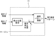
- FIG. 3 is a block diagram showing the configuration of the second generation unit 11 according to the first embodiment.
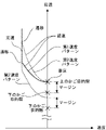
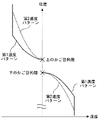
- 4 and 5 are diagrams showing an example of the speed pattern of the elevator 1 according to the first embodiment.
- FIG. 6 is a flowchart showing an example of the operation of the elevator 1 according to the first embodiment.
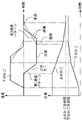
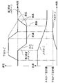
- 7 and 8 are diagrams showing an example of a time-series waveform of the movement of the elevator 1 according to the first embodiment.
- the control of the above car 3 will be described.
- the upper car 3 is an example of the first car.
- the lower car 3 adjacent to the upper car 3 is an example of the second car.
- the lower car 3 is also an example of the first car.
- the upper car 3 is also an example of the second car.
- the car 3 is another example of the first car.
- the car 3 adjacent to the upper side or the lower side of the car 3 is another example of the second car.
- the information acquisition unit 9 of the control panel 8 corresponding to the upper car 3 acquires the own car information about the upper car 3 and the other car information about the lower car 3. Based on the information acquired by the information acquisition unit 9, the first generation unit 10 generates the first velocity pattern. Further, the second generation unit 11 generates a second speed pattern based on the information acquired by the information acquisition unit 9.
- FIG. 3 shows an example of calculation of the reference of the second speed pattern.
- the second generation unit 11 has a margin in the direction of the upper car 3 from the position where the lower car 3 stops in the second speed pattern of the upper car 3. Generate based on the position.
- the second generation unit 11 acquires the target floor of the lower car 3 based on the other car information.
- the second generation unit 11 sets the position of the acquired target floor of the lower car 3 as the position where the lower car 3 stops.
- the second generation unit 11 uses the inter-floor distance from the target floor of the upper car 3 to the floor adjacent to the lower floor as a margin.
- the second generation unit 11 generates the second speed pattern of the upper car 3 with reference to the position where the lower car 3 stops and the margin is added.
- the second generation unit 11 uses a different margin for each target floor of the upper car 3 to perform a second speed pattern. May be generated.
- the second generation unit 11 of the control panel 8 corresponding to the car 3 is the car 3.
- the standard calculation method may be selected according to the traveling direction. For example, when the car 3 arranged in the middle descends, the second generation unit 11 of the control panel 8 corresponding to the car 3 is based on a position where a margin is added to the position where the car 3 adjacent to the lower side stops. And. On the other hand, when the car 3 arranged in the middle rises, the second generation unit 11 of the control panel 8 corresponding to the car 3 is based on the position where the margin is subtracted from the position where the car 3 adjacent above stops. And.
- the horizontal axis represents the speed of the car 3 with the ascending direction as positive.
- the vertical axis represents the position of the car 3.
- the first generation unit 10 In the control panel 8 corresponding to the upper car 3, the first generation unit 10 generates the first speed pattern of the upper car 3 based on the own car information acquired by the information acquisition unit 9. The first speed pattern of the upper car 3 is based on the position of the destination floor of the upper car 3.
- the first speed pattern includes the phases of constant speed operation, transition operation, deceleration operation, and landing operation in this order.
- the phase in the first speed pattern of the upper car 3 is switched according to the distance from the position of the upper car 3 to the position of the destination floor of the upper car 3, for example.
- the transition operation is a phase in which the constant speed operation is changed to the deceleration operation.
- the acceleration of the upper car 3 changes from 0 to a constant jerk, for example, from the jerk in the deceleration operation.
- Implantation operation is a phase in which the magnitude of deceleration decreases monotonically after deceleration operation until it stops.
- the acceleration of the upper car 3 changes with a constant jerk from the deceleration in the deceleration operation to 0, for example.
- the second generation unit 11 In the control panel 8 corresponding to the upper car 3, the second generation unit 11 generates the second speed pattern of the upper car 3 based on the own car information and the other car information acquired by the information acquisition unit 9.
- the reference of the second speed pattern is the position of the floor below the destination floor of the upper car 3.
- the reference of the second speed pattern is lower than the reference of the first speed pattern.
- the reference of the second speed pattern is the position of the destination floor of the upper car 3. That is, the reference of the second speed pattern matches the reference of the first speed pattern. In this way, the second generation unit 11 generates the second speed pattern according to the situation of the lower car 3.
- the second speed pattern like the first speed pattern, includes the phases of constant speed operation, transition operation, deceleration operation, and landing operation in this order.
- the phase in the second speed pattern of the upper car 3 is switched according to, for example, the distance from the position of the upper car 3 to the reference of the second speed pattern.
- the magnitude of the deceleration during the deceleration operation of the second speed pattern is smaller than the magnitude of the deceleration during the deceleration operation of the first speed pattern. Therefore, the distance between the position and the reference for shifting to the deceleration operation in the second speed pattern is longer than the distance between the position and the reference for shifting to the deceleration operation in the first speed pattern.
- the speed of the upper car 3 during deceleration operation in the second speed pattern based on the same position as the first speed pattern is slower than the speed in the first speed pattern when the upper car 3 is in the same position. Become.
- FIG. 5 shows an example in which the destination floor of the lower car 3 is a floor adjacent to the destination floor of the upper car 3.
- the control panel 8 corresponding to the lower car 3 generates the first speed pattern and the second speed pattern of the lower car 3 in the same manner as the control panel 8 corresponding to the upper car 3.
- FIG. 6 shows an example of operation for each control cycle in the control panel 8 corresponding to the above car 3.
- step S11 the first generation unit 10 generates the first velocity pattern. Then, in step S12, the second generation unit 11 generates a second velocity pattern.
- step S13 the comparison unit 13 compares the first speed pattern and the second speed pattern, for example, as follows.
- the comparison unit 13 calculates the velocity of the upper car 3 at the current position based on the first velocity pattern.
- the comparison unit 13 calculates the velocity of the upper car 3 at the current position based on the second velocity pattern.
- the comparison unit 13 determines whether the speed calculated based on the second speed pattern is slower than the speed calculated based on the first speed pattern. If the determination result is Yes, the operation of the control panel 8 proceeds to step S14. On the other hand, when the determination result is No, the operation of the control panel 8 proceeds to step S15.
- step S14 the comparison unit 13 inputs the second speed pattern to the signal generation unit 14.
- the signal generation unit 14 generates the control signal of the upper car 3 based on the input second speed pattern.
- the signal generation unit 14 controls the raising and lowering of the upper car 3 by outputting the generated control signal to the hoisting machine 5 corresponding to the upper car 3. After that, the operation of the control panel 8 for each control cycle ends.
- step S15 the comparison unit 13 inputs the first velocity pattern to the signal generation unit 14.
- the signal generation unit 14 generates the control signal of the upper car 3 based on the input first speed pattern.
- the signal generation unit 14 controls the raising and lowering of the upper car 3 by outputting the generated control signal to the hoisting machine 5 corresponding to the upper car 3. After that, the operation of the control panel 8 for each control cycle ends.
- FIG. 7 shows an example of the movement of the upper car 3 and the lower car 3.
- the upper graph of FIG. 7 shows the time series waveform of the speed of the car 3.
- the horizontal axis represents time.
- the vertical axis represents the speed of the car 3 with the ascending direction as positive.
- the lower graph in FIG. 7 shows the time series waveform of the position of the car 3.
- the horizontal axis represents time.
- the vertical axis represents the position of the car 3.
- FIG. 7 shows an example in which the lower car 3 first rises toward the destination floor and then the upper car 3 descends toward the destination floor. In this example, the destination floor of the lower car 3 is adjacent to the destination floor of the upper car 3.
- the time-series waveform shown here is an example shown for explanation, and the movement of the plurality of baskets 3 in the elevator 1 is not limited to this.
- the first speed pattern and the second speed pattern match at the position where the constant speed operation is performed in the second speed pattern of the upper car 3. Therefore, when the upper car 3 is in this position, the elevating control unit 12 controls the elevating and lowering of the upper car 3 based on the first speed pattern or the second speed pattern.
- the second speed pattern is slower than the first speed pattern at the position where the deceleration operation is performed in the second speed pattern of the upper car 3. Therefore, when the upper car 3 is in this position, the elevating control unit 12 controls the elevating of the upper car 3 based on the second speed pattern. Since the second speed pattern shifts to the deceleration operation at a position farther from the reference than the first speed pattern, the upper car 3 starts deceleration earlier than the case of moving up and down based on the first speed pattern. Further, the upper car 3 decelerates at a deceleration smaller in size than when moving up and down based on the first speed pattern. In this way, when the upper car 3 is close to the lower car 3, the upper car 3 lands on the destination floor at a low speed based on the second speed pattern.
- the lower car 3 also lands on the destination floor at a low speed based on the second speed pattern.
- FIG. 8 shows another example of the movement of the upper car 3 and the lower car 3.
- the upper graph of FIG. 8 represents the time-series waveform of the velocity of the car 3 in the same manner as the upper graph of FIG. 7.
- the lower graph of FIG. 8 shows the time-series waveform of the position of the car 3 in the same manner as the lower graph of FIG. 7.
- FIG. 8 shows an example in which the destination floor of the lower car 3 is two or more floors below the destination floor of the upper car 3.
- the time-series waveform shown here is an example shown for explanation, and the movement of the plurality of baskets 3 in the elevator 1 is not limited to this.
- the reference of the second speed pattern is lower than the reference of the first speed pattern.
- the first speed pattern is a slower speed pattern than the second speed pattern. Therefore, the elevating control unit 12 controls the elevating of the upper car 3 based on the first speed pattern.
- the upper car 3 decelerates with a larger deceleration than when moving up and down based on the second speed pattern. In this way, when the upper car 3 and the lower car 3 are separated, the upper car 3 aims at a speed that prioritizes the operation efficiency based on the first speed pattern that does not depend on the situation of the lower car 3. Land on the floor.
- the lower car 3 also lands on the destination floor at a speed that prioritizes operation efficiency based on the first speed pattern that does not depend on the situation of the lower car 3.
- the elevator 1 includes a plurality of baskets 3, a first generation unit 10, a second generation unit 11, and an elevating control unit 12.
- the plurality of car 3 includes the upper car 3 and the lower car 3.
- the upper car 3 and the lower car 3 are arranged in the hoistway 2.
- the upper car 3 and the lower car 3 move up and down in the vertical direction.
- the lower car 3 is arranged so as to overlap each other in the horizontal projection plane with the upper car 3.
- the lower car 3 is vertically adjacent to the upper car 3.
- the first generation unit 10 generates the first velocity pattern.
- the first speed pattern is the relationship between the position and speed of the upper car 3 with respect to the position of the destination floor of the upper car 3.
- the second generation unit 11 generates a second speed pattern so that the speed of the upper car 3 does not exceed the limit speed.
- the second speed pattern is a relationship between the position and speed of the upper car 3 with respect to a position with a margin in the direction of the upper car 3 from the position where the lower car 3 stops.
- the limit speed is the upper limit speed at which the upper car 3 does not collide with the lower car 3 when the upper car 3 is stopped by the braking device 7.
- the elevating control unit 12 controls the elevating of the upper car 3 based on the slower speed of the first speed pattern and the second speed pattern at the current position of the upper car 3.
- the second generation unit 11 generates the second speed pattern so that the magnitude of the deceleration during the deceleration operation in the second speed pattern is smaller than the magnitude of the deceleration during the deceleration operation in the first speed pattern.
- the car 3 controlled based on the second speed pattern will land at a lower speed than when controlled based on the first speed pattern. Therefore, it becomes easy to avoid a collision with a car 3 adjacent to the car 3 in the vertical direction.
- the second generation unit 11 generates the second speed pattern by setting the position where the lower car 3 stops as the position of the target floor of the lower car 3.
- the second generation unit 11 can more accurately acquire the stop position of the adjacent car 3. Therefore, it becomes easy to avoid a collision with a car 3 adjacent to the car 3 in the vertical direction.
- the second generation unit 11 generates the second speed pattern with the margin as the inter-floor distance from the target floor of the upper car 3 to the floor adjacent to the lower car 3 side.
- the limit speed is calculated based on the deceleration by the braking device 7, the delay time of the operation of the braking device 7, and the distance between the position of the destination floor of the upper car 3 and the current position of the upper car 3. To.
- the limit speed can be easily calculated based on known information such as design values and receivable information. Therefore, the calculation or design of the second velocity pattern becomes easy.
- the second generation unit 11 may generate a second speed pattern with a margin larger than the normal time. For example, when focusing on the control of the upper car 3, the second setting unit may take a margin larger than the inter-floor distance from the target floor of the upper car 3 to the floor adjacent to the lower car 3 side. In maintenance work, maintenance personnel may perform the work on the car 3. In such a case, the workability of maintenance personnel is improved.
- FIG. 9 is a hardware configuration diagram of a main part of the elevator 1 according to the first embodiment.
- Each function of elevator 1 can be realized by a processing circuit.
- the processing circuit includes at least one processor 100a and at least one memory 100b.
- the processing circuit may include at least one dedicated hardware 200 with or as a substitute for the processor 100a and the memory 100b.
- each function of the elevator 1 is realized by software, firmware, or a combination of software and firmware. At least one of the software and firmware is written as a program.
- the program is stored in the memory 100b.
- the processor 100a realizes each function of the elevator 1 by reading and executing the program stored in the memory 100b.
- the processor 100a is also referred to as a CPU (Central Processing Unit), a processing device, a computing device, a microprocessor, a microcomputer, and a DSP.
- the memory 100b is composed of, for example, a non-volatile or volatile semiconductor memory such as a RAM, a ROM, a flash memory, an EPROM, or an EEPROM.
- the processing circuit includes the dedicated hardware 200
- the processing circuit is realized by, for example, a single circuit, a composite circuit, a programmed processor, a parallel programmed processor, an ASIC, an FPGA, or a combination thereof.
- Each function of elevator 1 can be realized by a processing circuit. Alternatively, each function of the elevator 1 can be collectively realized by a processing circuit. For each function of the elevator 1, a part may be realized by the dedicated hardware 200, and the other part may be realized by software or firmware. In this way, the processing circuit realizes each function of the elevator 1 with the dedicated hardware 200, software, firmware, or a combination thereof.
- FIG. 10 is a diagram showing an example of a speed pattern of the elevator 1 according to the second embodiment.
- FIG. 11 is a flowchart showing an example of the operation of the elevator 1 according to the second embodiment.
- FIG. 12 is a diagram showing an example of a time-series waveform of the movement of the elevator 1 according to the second embodiment.
- the control panel 8 also controls the corresponding car 3 for the lower car 3 or the other car 3 in the case where the elevator 1 is provided with three or more cars 3.
- the horizontal axis represents the speed of the car 3 with the ascending direction as positive.
- the vertical axis represents the position of the car 3.
- the second generation unit 11 In the control panel 8 corresponding to the upper car 3, the second generation unit 11 generates a plurality of sub-patterns of the upper car 3 based on the own car information and the other car information acquired by the information acquisition unit 9.
- each sub-pattern represents the relationship between the position and the speed of the car 3.
- each sub-pattern is generated in the same manner as the second speed pattern of the car 3.
- each sub-pattern is generated with a margin from the position where the other car 3 adjacent to the car 3 stops in the direction of the car 3 in which the sub-pattern is generated.
- the reference position is the position where the speed of the car 3 becomes zero.
- each sub-pattern is generated so as not to exceed the limit speed of the car 3.
- the second generation unit 11 generates two sub-patterns.
- the magnitude of deceleration during deceleration operation of one subpattern is smaller than the magnitude of deceleration during deceleration of the other subpattern.
- the margin of the deceleration subpattern with the smaller deceleration magnitude is shorter than the margin of the high deceleration subpattern with the smaller deceleration magnitude. That is, the reference for the high deceleration subpattern is above the margin of the reduction rate subpattern.
- the standard of the reduction speed sub-pattern matches the standard of the first speed pattern.
- the position of shifting to deceleration operation in the high deceleration sub-pattern is set to be higher than the position of shifting to deceleration operation in the first speed pattern.
- the magnitude of the deceleration of the high deceleration sub-pattern may be greater than the magnitude of the deceleration of the first velocity pattern.
- the magnitude of the deceleration of the high deceleration sub-pattern may be less than or equal to the magnitude of the deceleration of the first velocity pattern.
- the second generation unit 11 generates a second speed pattern so as to switch to a sub-pattern with a higher speed at the current position of the upper car 3 among the generated plurality of speed patterns.
- the second speed pattern is a speed pattern that shifts from constant speed operation to deceleration operation of a high deceleration sub-pattern, then switches to deceleration operation of a reduction speed sub-pattern, and stops after landing operation. ..
- the reference of the second generation unit 11 becomes the reference of the sub-pattern of the reduction speed.
- FIG. 11 shows an example of operation for each control cycle in the control panel 8 corresponding to the upper car 3.
- step S21 the first generation unit 10 generates the first velocity pattern.
- step S22 the second generation unit 11 generates a sub-pattern of the reduction rate.
- step S23 the second generation unit 11 generates a high deceleration sub-pattern.
- step S24 the second generation unit 11 compares the reduction rate sub-pattern and the high deceleration sub-pattern, for example, as follows.
- the second generation unit 11 calculates the speed of the upper car 3 at the current position based on the reduction speed sub-pattern.
- the second generation unit 11 calculates the speed of the upper car 3 at the current position based on the high deceleration sub-pattern.
- the second generation unit 11 determines whether the speed calculated based on the reduction speed sub-pattern is slower than the speed calculated based on the high deceleration sub-pattern first speed pattern.
- step S25 the second generation unit 11 sets the high deceleration sub-pattern as the second speed pattern.
- step S26 the second generation unit 11 sets the reduction speed sub-pattern as the second speed pattern.
- step S27 the comparison unit 13 compares the first speed pattern and the second speed pattern, for example, as follows.
- the comparison unit 13 calculates the velocity of the upper car 3 at the current position based on the first velocity pattern.
- the comparison unit 13 calculates the velocity of the upper car 3 at the current position based on the second velocity pattern.
- the comparison unit 13 determines whether the speed calculated based on the second speed pattern is slower than the speed calculated based on the first speed pattern. If the determination result is Yes, the operation of the control panel 8 proceeds to step S28. On the other hand, when the determination result is No, the operation of the control panel 8 proceeds to step S29.
- step S28 the comparison unit 13 inputs the second speed pattern to the signal generation unit 14.
- the signal generation unit 14 generates the control signal of the upper car 3 based on the input second speed pattern.
- the signal generation unit 14 controls the raising and lowering of the upper car 3 by outputting the generated control signal to the hoisting machine 5 corresponding to the upper car 3. After that, the operation of the control panel 8 for each control cycle ends.
- step S29 the comparison unit 13 inputs the first velocity pattern to the signal generation unit 14.
- the signal generation unit 14 generates the control signal of the upper car 3 based on the input first speed pattern.
- the signal generation unit 14 controls the raising and lowering of the upper car 3 by outputting the generated control signal to the hoisting machine 5 corresponding to the upper car 3. After that, the operation of the control panel 8 for each control cycle ends.
- FIG. 12 shows an example of the movement of the upper car 3 and the lower car 3.
- the upper graph of FIG. 12 represents the time-series waveform of the velocity of the car 3 in the same manner as the upper graph of FIG. 7.
- the lower graph of FIG. 12 represents the time-series waveform of the position of the car 3 in the same manner as the lower graph of FIG. 7.
- FIG. 12 shows an example in which the lower car 3 first rises toward the destination floor and then the upper car 3 descends toward the destination floor. In this example, the destination floor of the lower car 3 is adjacent to the destination floor of the upper car 3.
- the time-series waveform shown here is an example shown for explanation, and the movement of the plurality of baskets 3 in the elevator 1 is not limited to this.
- the first speed pattern and the second speed pattern match at the position where the constant speed operation is performed in the second speed pattern of the upper car 3. Therefore, when the upper car 3 is in this position, the elevating control unit 12 controls the elevating and lowering of the upper car 3 based on the first speed pattern or the second speed pattern.
- the second speed pattern is slower than the first speed pattern at the position where the deceleration operation is performed in the second speed pattern of the upper car 3. Therefore, when the upper car 3 is in this position, the elevating control unit 12 controls the elevating of the upper car 3 based on the second speed pattern. Since the second speed pattern shifts to the deceleration operation at a position farther from the reference than the first speed pattern, the upper car 3 starts deceleration earlier than the case of moving up and down based on the first speed pattern. At this time, the upper car 3 is decelerated by the deceleration of the high deceleration sub-pattern. After that, the upper car 3 is decelerated by the deceleration of the sub-pattern of the reduction speed. In this way, when the upper car 3 is close to the lower car 3, the upper car 3 lands on the destination floor at a low speed based on the second speed pattern.
- the second generation unit 11 of the elevator 1 has a plurality of sub-patterns relating to the position and speed of the upper car 3, and the speed of the upper car 3 is the limit speed. Generate so that it does not exceed.
- the second generation unit 11 generates a second speed pattern so as to switch to a sub-pattern having a higher speed at the current position of the upper car 3 among the plurality of sub-patterns.
- the traveling time between the floors of the upper car 3 is shortened.
- the distance to go up and down in constant speed operation before deceleration operation in the second speed pattern is set as compared with the case of deceleration at a constant deceleration in deceleration operation. It can be taken for a long time. As a result, the operating efficiency of the elevator 1 is less likely to decrease.
- FIG. 13 is a diagram showing an example of the speed pattern of the elevator 1 according to the third embodiment.
- FIG. 14 is a diagram showing an example of a time-series waveform of the movement of the elevator 1 according to the third embodiment.
- the control panel 8 also controls the corresponding car 3 for the lower car 3 or the other car 3 in the case where the elevator 1 is provided with three or more cars 3.
- the horizontal axis represents the speed of the car 3 with the ascending direction as positive.
- the vertical axis represents the position of the car 3.
- the second generation unit 11 In the control panel 8 corresponding to the upper car 3, the second generation unit 11 generates the second speed pattern of the upper car 3 based on the own car information and the other car information acquired by the information acquisition unit 9.
- the reference of the second velocity pattern matches the reference of the first velocity pattern.
- the time of the landing operation of the second speed pattern is longer than the time of the landing operation of the first speed pattern.
- the magnitude of the deceleration during the deceleration operation of the second speed pattern may be less than or equal to the magnitude of the deceleration during the deceleration operation of the first speed pattern.
- the deceleration of the upper car 3 gradually decreases from the deceleration during the deceleration operation to the stop.
- the position of shifting to deceleration operation in the second speed pattern is higher than the position of shifting to deceleration operation in the first speed pattern. Further, the speed of the upper car 3 during deceleration operation in the second speed pattern based on the same position as the first speed pattern is slower than the speed in the first speed pattern when the upper car 3 is in the same position. Become.
- FIG. 14 shows an example of the movement of the upper car 3 and the lower car 3.
- the upper graph of FIG. 14 represents the time-series waveform of the velocity of the car 3 in the same manner as the upper graph of FIG. 7.
- the lower graph of FIG. 14 represents the time-series waveform of the position of the car 3 in the same manner as the lower graph of FIG. 7.
- FIG. 14 shows an example in which the lower car 3 first rises toward the destination floor and then the upper car 3 descends toward the destination floor. In this example, the destination floor of the lower car 3 is adjacent to the destination floor of the upper car 3.
- the time-series waveform shown here is an example shown for explanation, and the movement of the plurality of baskets 3 in the elevator 1 is not limited to this.
- the first speed pattern and the second speed pattern match at the position where the constant speed operation is performed in the second speed pattern of the upper car 3. Therefore, when the upper car 3 is in this position, the elevating control unit 12 controls the elevating and lowering of the upper car 3 based on the first speed pattern or the second speed pattern.
- the second speed pattern is slower than the first speed pattern at the position where the deceleration operation is performed in the second speed pattern of the upper car 3. Therefore, when the upper car 3 is in this position, the elevating control unit 12 controls the elevating of the upper car 3 based on the second speed pattern. Since the second speed pattern shifts to the deceleration operation at a position farther from the reference than the first speed pattern, the upper car 3 starts deceleration earlier than the case of moving up and down based on the first speed pattern. Further, the upper car 3 lands on the target floor by a landing operation for a longer time than when ascending and descending based on the first speed pattern.
- the deceleration of the upper car 3 gradually decreases from the deceleration during the deceleration operation to the stop. In this way, when the upper car 3 is close to the lower car 3, the upper car 3 lands on the destination floor at a low speed based on the second speed pattern.
- the time of the landing operation in the second speed pattern is longer than the time of the landing operation in the first speed pattern. Generates a two-velocity pattern.
- FIG. 15 is a block diagram showing the configuration of the second generation unit 11 according to the fourth embodiment.
- FIG. 16 is a diagram showing an example of the speed pattern of the elevator 1 according to the fourth embodiment.
- the control panel 8 also controls the corresponding car 3 for the lower car 3 or the other car 3 in the case where the elevator 1 is provided with three or more cars 3.
- FIG. 15 shows an example of calculation of the reference of the second speed pattern.
- the second generation unit 11 acquires information such as the position and speed of the lower car 3 based on the other car information.
- the second generation unit 11 estimates the target floor of the lower car 3 as follows, for example, based on the acquired information such as the position and speed of the lower car 3.
- the second generation unit 11 assumes, for example, the first speed pattern of the lower car 3 with each floor as the target floor.
- the second generation unit 11 estimates the floor that is highly consistent with the acquired position and speed of the lower car 3 among the floors assuming the first speed pattern as the target floor of the lower car 3.
- the second generation unit 11 sets the estimated position of the target floor of the lower car 3 as the position where the lower car 3 stops.
- the second generation unit 11 generates the second speed pattern of the upper car 3 with reference to the position where the lower car 3 stops and the margin is added.
- the horizontal axis represents the speed of the car 3 with the ascending direction as positive.
- the vertical axis represents the position of the car 3.
- the second generation unit 11 In the control panel 8 corresponding to the upper car 3, the second generation unit 11 generates the second speed pattern of the upper car 3 based on the own car information and the other car information acquired by the information acquisition unit 9.
- the standard of the second speed pattern is the position of the floor below the destination floor of the upper car 3.
- the reference of the second speed pattern is lower than the reference of the first speed pattern.
- the reference of the second speed pattern is the position of the destination floor of the upper car 3. That is, the reference of the second speed pattern matches the reference of the first speed pattern.
- the second generation unit 11 generates the second velocity pattern according to the estimation about the target floor of the lower car 3.
- the second generation unit 11 since the target floor is discrete information, the second generation unit 11 generates the second speed pattern so as to be discretely switched according to the situation such as the position and speed of the lower car 3.
- the second generation unit 11 of the elevator 1 estimates the target floor of the lower car 3 based on the position and speed of the lower car 3.
- the second generation unit 11 generates a second speed pattern with the position where the lower car 3 stops as the estimated position of the target floor of the lower car 3.
- the elevator 1 can be controlled more stably, in which the operation efficiency is less likely to decrease and the collision of the cars 3 adjacent to each other in the vertical direction is easily avoided.
- FIG. 17 is a block diagram showing the configuration of the second generation unit 11 according to the fifth embodiment.
- FIG. 18 is a diagram showing an example of a speed pattern of the elevator 1 according to the fifth embodiment.
- the control panel 8 also controls the corresponding car 3 for the lower car 3 or the other car 3 in the case where the elevator 1 is provided with three or more cars 3.
- FIG. 17 shows an example of calculation of the reference of the second speed pattern.
- the second generation unit 11 acquires information such as the position and speed of the lower car 3 based on the other car information.
- the second generation unit 11 estimates the stoptable position of the lower car 3 based on the acquired information such as the position and speed of the lower car 3, for example, as follows.
- the second generation unit 11 moves up and down from the current position and speed of the lower car 3 until the lower car 3 stops when stopped by the same deceleration as the first speed pattern of the lower car 3. Is calculated.
- the second generation unit 11 estimates a position separated from the current position of the lower car 3 in the traveling direction of the lower car 3 by the calculated distance as a position where the lower car 3 can be stopped due to an error.
- the second generation unit 11 sets the position where the lower car 3 stops is the estimated stop position of the lower car 3.
- the second generation unit 11 generates the second speed pattern of the upper car 3 with reference to the position where the lower car 3 stops and the margin is added.
- the horizontal axis represents the speed of the car 3 with the ascending direction as positive.
- the vertical axis represents the position of the car 3.
- the second generation unit 11 In the control panel 8 corresponding to the upper car 3, the second generation unit 11 generates the second speed pattern of the upper car 3 based on the own car information and the other car information acquired by the information acquisition unit 9. If the estimated stoptable position of the lower car 3 is below the position of the floor adjacent to the destination floor of the upper car 3, the reference of the second speed pattern is the position of the destination floor of the upper car 3. It will be lower. At this time, the reference of the second speed pattern is lower than the reference of the first speed pattern. On the other hand, when the estimated stoptable position of the lower car 3 is the position of the floor adjacent to the destination floor of the upper car 3, the reference of the second speed pattern is the position of the destination floor of the upper car 3. Will be.
- the reference of the second speed pattern matches the reference of the first speed pattern.
- the second generation unit 11 generates the second speed pattern according to the estimation of the stoptable position of the lower car 3.
- the second generation unit 11 since the stoptable position is continuous information, the second generation unit 11 generates so as to continuously move the second speed pattern according to the situation such as the position and speed of the lower car 3. do.
- the second generation unit 11 of the elevator 1 estimates the stoptable position from the current position and speed of the lower car 3.
- the second generation unit 11 generates the second speed pattern by setting the position where the lower car 3 stops as the estimated stoptable position for the lower car 3.
- the elevator 1 can be controlled more stably, in which the operation efficiency is less likely to decrease and the collision of the cars 3 adjacent to each other in the vertical direction is easily avoided. Further, since the second velocity pattern is generated so as to move continuously, the control of the upper car 3 is performed based on the continuously changing velocity pattern. Therefore, the elevator 1 is controlled more stably.
- An operation test may be conducted when installing the elevator 1.
- the operation test includes a test of controlling the raising and lowering of the car 3 by the control panel 8.
- an operation test may be performed in a state where only one of the cars 3 arranged so as to be adjacent to each other in the vertical direction is installed.
- the second generation unit 11 of the control panel 8 corresponding to the already installed car 3 sets the position where the other car 3 adjacent in the vertical direction stops in a virtual manner preset in the operation test.
- a second velocity pattern may be generated as a suitable position.
- the other car 3 may not be installed yet.
- the virtual position may be input to the control panel 8 from the outside.
- the virtual position is the position in the hoistway 2.
- the elevator according to this disclosure can be applied to buildings with multiple floors.
Landscapes
- Engineering & Computer Science (AREA)
- Automation & Control Theory (AREA)
- Civil Engineering (AREA)
- Mechanical Engineering (AREA)
- Structural Engineering (AREA)
- Elevator Control (AREA)
Abstract
Description
図1は、実施の形態1に係るエレベーター1の構成図である。
図2Aおよび図2Bは、実施の形態1に係るエレベーター1における制動距離の例を説明する図である。
図2Aおよび図2Bにおいて、横軸は上昇する方向を正としたかご3の速度を表す。縦軸はかご3の位置を表す。図2Aおよび図2Bにおいて、位置X0においてかご3に異常が発生する場合の例が示される。







図3は、実施の形態1に係る第2生成部11の構成を示すブロック図である。
図4および図5は、実施の形態1に係るエレベーター1の速度パターンの例を示す図である。
図6は、実施の形態1に係るエレベーター1の動作の例を示すフローチャートである。
図7および図8は、実施の形態1に係るエレベーター1の運動の時系列波形の例を示す図である。
図9は、実施の形態1に係るエレベーター1の主要部のハードウェア構成図である。
図10は、実施の形態2に係るエレベーター1の速度パターンの例を示す図である。
図11は、実施の形態2に係るエレベーター1の動作の例を示すフローチャートである。
図12は、実施の形態2に係るエレベーター1の運動の時系列波形の例を示す図である。
図13は、実施の形態3に係るエレベーター1の速度パターンの例を示す図である。
図14は、実施の形態3に係るエレベーター1の運動の時系列波形の例を示す図である。
図15は、実施の形態4に係る第2生成部11の構成を示すブロック図である。
図16は、実施の形態4に係るエレベーター1の速度パターンの例を示す図である。
図17は、実施の形態5に係る第2生成部11の構成を示すブロック図である。
図18は、実施の形態5に係るエレベーター1の速度パターンの例を示す図である。
Claims (11)
- 昇降路に配置され、鉛直方向に昇降する第1かごと、
前記昇降路において第1かごと水平投影面内において互いに重なりを持つように配置され、前記第1かごに鉛直方向において隣接し、鉛直方向に昇降する第2かごと、
前記第1かごの目的階の位置を基準とする前記第1かごの位置および速度の関係である第1速度パターンを生成する第1生成部と、
前記第2かごが停止する位置から前記第1かごの方向にマージンを空けた位置を基準とする前記第1かごの位置および速度の関係である第2速度パターンを、前記第1かごが制動装置によって制動停止する場合に前記第1かごが前記第2かごに衝突しない上限の限界速度を前記第1かごの速度が超えないように生成する第2生成部と、
前記第1速度パターンおよび前記第2速度パターンのうち前記第1かごの現在の位置における速度が遅い方に基づいて、前記第1かごの昇降の制御を行う昇降制御部と、
を備えるエレベーター。 - 前記第2生成部は、前記第2速度パターンにおける減速運転中の減速度の大きさが前記第1速度パターンにおける減速運転中の減速度の大きさより小さくなるように前記第2速度パターンを生成する
請求項1に記載のエレベーター。 - 前記第2生成部は、前記第2速度パターンにおける着床運転の時間が前記第1速度パターンにおける着床運転の時間より長くなるように前記第2速度パターンを生成する
請求項1に記載のエレベーター。 - 前記第2生成部は、前記第1かごの位置および速度の関係である複数のサブパターンを前記第1かごの速度が前記限界速度を超えないように生成し、前記複数のサブパターンのうち前記第1かごの現在の位置における速度が速いサブパターンに切り替えるように前記第2速度パターンを生成する
請求項1に記載のエレベーター。 - 前記第2生成部は、前記第2かごが停止する位置を、前記第2かごの目的階の位置として前記第2速度パターンを生成する
請求項1から請求項4のいずれか一項に記載のエレベーター。 - 前記第2生成部は、前記第2かごの位置および速度に基づいて前記第2かごの目的階を推定し、前記第2かごが停止する位置を、推定した前記第2かごの目的階の位置として前記第2速度パターンを生成する
請求項1から請求項4のいずれか一項に記載のエレベーター。 - 前記第2生成部は、前記第2かごの現在の位置および速度から停止可能な位置を推定し、前記第2かごが停止する位置を、推定した停止可能な位置として前記第2速度パターンを生成する
請求項1から請求項4のいずれか一項に記載のエレベーター。 - 前記第2生成部は、前記マージンを、前記第1かごの目的階から前記第2かご側に隣接する階床までの階間距離として前記第2速度パターンを生成する
請求項1から請求項7のいずれか一項に記載のエレベーター。 - 前記第2生成部は、前記制動装置による減速度、前記制動装置の作動の遅れ時間、ならびに前記第1かごの目的階の位置および前記第1かごの現在の位置の間の距離に基づいて算出される前記限界速度を前記第1かごの速度が超えないように前記第2速度パターンを生成する
請求項1から請求項8のいずれか一項に記載のエレベーター。 - 前記第2生成部は、保守作業が行われるときに、前記マージンを、前記第1かごの目的階から前記第2かご側に隣接する階床までの階間距離より大きい距離として前記第2速度パターンを生成する
請求項1から請求項9のいずれか一項に記載のエレベーター。 - 前記第2生成部は、動作試験が行われるときに、前記第2かごが停止する位置を、前記動作試験において予め設定された仮想的な位置として前記第2速度パターンを生成する
請求項1から請求項10のいずれか一項に記載のエレベーター。
Priority Applications (3)
| Application Number | Priority Date | Filing Date | Title |
|---|---|---|---|
| JP2022560565A JP7332058B2 (ja) | 2020-11-05 | 2020-11-05 | マルチカーエレベーター |
| CN202080103698.3A CN116157348B (zh) | 2020-11-05 | 2020-11-05 | 多轿厢电梯 |
| PCT/JP2020/041390 WO2022097231A1 (ja) | 2020-11-05 | 2020-11-05 | マルチカーエレベーター |
Applications Claiming Priority (1)
| Application Number | Priority Date | Filing Date | Title |
|---|---|---|---|
| PCT/JP2020/041390 WO2022097231A1 (ja) | 2020-11-05 | 2020-11-05 | マルチカーエレベーター |
Publications (1)
| Publication Number | Publication Date |
|---|---|
| WO2022097231A1 true WO2022097231A1 (ja) | 2022-05-12 |
Family
ID=81457042
Family Applications (1)
| Application Number | Title | Priority Date | Filing Date |
|---|---|---|---|
| PCT/JP2020/041390 Ceased WO2022097231A1 (ja) | 2020-11-05 | 2020-11-05 | マルチカーエレベーター |
Country Status (3)
| Country | Link |
|---|---|
| JP (1) | JP7332058B2 (ja) |
| CN (1) | CN116157348B (ja) |
| WO (1) | WO2022097231A1 (ja) |
Citations (7)
| Publication number | Priority date | Publication date | Assignee | Title |
|---|---|---|---|---|
| JP2005104670A (ja) * | 2003-09-30 | 2005-04-21 | Mitsubishi Electric Corp | ワンシャフトマルチカー方式エレベーターの制御装置 |
| JP2007055692A (ja) * | 2005-08-22 | 2007-03-08 | Yaskawa Electric Corp | シングルシャフトマルチカーエレベータシステムおよびその群管理装置 |
| JP2008063017A (ja) * | 2006-09-04 | 2008-03-21 | Toshiba Elevator Co Ltd | エレベータの群管理制御装置 |
| JP2010523445A (ja) * | 2007-08-07 | 2010-07-15 | テュセンクルプ エレベーター アーゲー | エレベータシステム |
| JP2010538948A (ja) * | 2007-09-18 | 2010-12-16 | オーチス エレベータ カンパニー | かご離間制御を含む多かご昇降路 |
| WO2013157070A1 (ja) * | 2012-04-16 | 2013-10-24 | 三菱電機株式会社 | マルチカー式エレベータ |
| CN110461748A (zh) * | 2017-03-29 | 2019-11-15 | 蒂森克虏伯电梯股份公司 | 多轿厢电梯系统和操作多轿厢电梯系统的方法 |
Family Cites Families (8)
| Publication number | Priority date | Publication date | Assignee | Title |
|---|---|---|---|---|
| JP3090769B2 (ja) * | 1992-04-08 | 2000-09-25 | 株式会社東芝 | 自走式エレベータの制御装置 |
| JP2001247265A (ja) * | 2000-03-08 | 2001-09-11 | Mitsubishi Electric Corp | エレベータ制御システム |
| JP2010254480A (ja) * | 2003-03-18 | 2010-11-11 | Mitsubishi Electric Corp | エレベータ装置 |
| JP2009539725A (ja) * | 2006-06-07 | 2009-11-19 | オーチス エレベータ カンパニー | 複数のかごが走行しているエレベータ昇降路内における離間保証 |
| JP5224737B2 (ja) * | 2007-07-02 | 2013-07-03 | 三菱電機株式会社 | マルチかごエレベーターの制御装置 |
| JP5107393B2 (ja) * | 2010-06-21 | 2012-12-26 | 三菱電機株式会社 | エレベータシステム |
| JP5462843B2 (ja) * | 2011-08-04 | 2014-04-02 | 株式会社日立製作所 | ダブルデッキエレベータおよびその制御方法 |
| JP6180591B2 (ja) * | 2016-06-22 | 2017-08-16 | 三菱電機株式会社 | マルチカー式エレベータ |
-
2020
- 2020-11-05 CN CN202080103698.3A patent/CN116157348B/zh active Active
- 2020-11-05 WO PCT/JP2020/041390 patent/WO2022097231A1/ja not_active Ceased
- 2020-11-05 JP JP2022560565A patent/JP7332058B2/ja active Active
Patent Citations (7)
| Publication number | Priority date | Publication date | Assignee | Title |
|---|---|---|---|---|
| JP2005104670A (ja) * | 2003-09-30 | 2005-04-21 | Mitsubishi Electric Corp | ワンシャフトマルチカー方式エレベーターの制御装置 |
| JP2007055692A (ja) * | 2005-08-22 | 2007-03-08 | Yaskawa Electric Corp | シングルシャフトマルチカーエレベータシステムおよびその群管理装置 |
| JP2008063017A (ja) * | 2006-09-04 | 2008-03-21 | Toshiba Elevator Co Ltd | エレベータの群管理制御装置 |
| JP2010523445A (ja) * | 2007-08-07 | 2010-07-15 | テュセンクルプ エレベーター アーゲー | エレベータシステム |
| JP2010538948A (ja) * | 2007-09-18 | 2010-12-16 | オーチス エレベータ カンパニー | かご離間制御を含む多かご昇降路 |
| WO2013157070A1 (ja) * | 2012-04-16 | 2013-10-24 | 三菱電機株式会社 | マルチカー式エレベータ |
| CN110461748A (zh) * | 2017-03-29 | 2019-11-15 | 蒂森克虏伯电梯股份公司 | 多轿厢电梯系统和操作多轿厢电梯系统的方法 |
Also Published As
| Publication number | Publication date |
|---|---|
| JP7332058B2 (ja) | 2023-08-23 |
| CN116157348A (zh) | 2023-05-23 |
| CN116157348B (zh) | 2025-11-18 |
| JPWO2022097231A1 (ja) | 2022-05-12 |
Similar Documents
| Publication | Publication Date | Title |
|---|---|---|
| JP5646047B2 (ja) | マルチカー式エレベータ及びその制御方法 | |
| JP5992035B2 (ja) | マルチカー式エレベータ | |
| JPWO2008117423A1 (ja) | エレベータのブレーキ装置 | |
| JP6256620B2 (ja) | エレベーター装置 | |
| KR20090010253A (ko) | 엘리베이터 장치 | |
| JP6299926B2 (ja) | エレベータの制御システム | |
| JP6180591B2 (ja) | マルチカー式エレベータ | |
| KR100931429B1 (ko) | 엘리베이터의 제어 장치 | |
| JP5224737B2 (ja) | マルチかごエレベーターの制御装置 | |
| JP7332058B2 (ja) | マルチカーエレベーター | |
| JP4397720B2 (ja) | エレベータ装置 | |
| JPWO2004031064A1 (ja) | エレベーターシステム | |
| JP4618636B2 (ja) | エレベータ装置 | |
| KR20210008167A (ko) | 엘리베이터 장치 | |
| WO2022049673A1 (ja) | エレベーター | |
| CN110770154B (zh) | 电梯装置 | |
| JP7826797B2 (ja) | エレベータの停電時運転装置 | |
| JP6223799B2 (ja) | エレベータの速度制御方法 | |
| JP5264145B2 (ja) | エレベータ制御装置 | |
| JP7315094B2 (ja) | エレベーターの安全監視装置 | |
| KR102205550B1 (ko) | 엘리베이터의 제어 장치 및 권상 로프의 신축량 추정 방법 | |
| KR100275576B1 (ko) | 엘리베이터 제어 장치 및 방법(elevator control apparatus and method) | |
| KR20230129549A (ko) | 엘리베이터 장치 | |
| KR20070069127A (ko) | 엘리베이터 장치 | |
| HK40076760B (zh) | 电梯的安全监视装置 |
Legal Events
| Date | Code | Title | Description |
|---|---|---|---|
| 121 | Ep: the epo has been informed by wipo that ep was designated in this application |
Ref document number: 20960784 Country of ref document: EP Kind code of ref document: A1 |
|
| ENP | Entry into the national phase |
Ref document number: 2022560565 Country of ref document: JP Kind code of ref document: A |
|
| WWE | Wipo information: entry into national phase |
Ref document number: 202080103698.3 Country of ref document: CN |
|
| NENP | Non-entry into the national phase |
Ref country code: DE |
|
| 122 | Ep: pct application non-entry in european phase |
Ref document number: 20960784 Country of ref document: EP Kind code of ref document: A1 |