WO2022092168A1 - ロボット制御装置及びロボットシステム - Google Patents
ロボット制御装置及びロボットシステム Download PDFInfo
- Publication number
- WO2022092168A1 WO2022092168A1 PCT/JP2021/039711 JP2021039711W WO2022092168A1 WO 2022092168 A1 WO2022092168 A1 WO 2022092168A1 JP 2021039711 W JP2021039711 W JP 2021039711W WO 2022092168 A1 WO2022092168 A1 WO 2022092168A1
- Authority
- WO
- WIPO (PCT)
- Prior art keywords
- robot
- image
- coordinate system
- control
- control device
- Prior art date
- Legal status (The legal status is an assumption and is not a legal conclusion. Google has not performed a legal analysis and makes no representation as to the accuracy of the status listed.)
- Ceased
Links
Images







Classifications
-
- B—PERFORMING OPERATIONS; TRANSPORTING
- B25—HAND TOOLS; PORTABLE POWER-DRIVEN TOOLS; MANIPULATORS
- B25J—MANIPULATORS; CHAMBERS PROVIDED WITH MANIPULATION DEVICES
- B25J9/00—Program-controlled manipulators
- B25J9/16—Program controls
- B25J9/1628—Program controls characterised by the control loop
- B25J9/1633—Program controls characterised by the control loop compliant, force, torque control, e.g. combined with position control
-
- B—PERFORMING OPERATIONS; TRANSPORTING
- B25—HAND TOOLS; PORTABLE POWER-DRIVEN TOOLS; MANIPULATORS
- B25J—MANIPULATORS; CHAMBERS PROVIDED WITH MANIPULATION DEVICES
- B25J13/00—Controls for manipulators
- B25J13/08—Controls for manipulators by means of sensing devices, e.g. viewing or touching devices
- B25J13/085—Force or torque sensors
-
- B—PERFORMING OPERATIONS; TRANSPORTING
- B25—HAND TOOLS; PORTABLE POWER-DRIVEN TOOLS; MANIPULATORS
- B25J—MANIPULATORS; CHAMBERS PROVIDED WITH MANIPULATION DEVICES
- B25J9/00—Program-controlled manipulators
- B25J9/16—Program controls
- B25J9/1679—Program controls characterised by the tasks executed
- B25J9/1687—Assembly, peg and hole, palletising, straight line, weaving pattern movement
-
- B—PERFORMING OPERATIONS; TRANSPORTING
- B25—HAND TOOLS; PORTABLE POWER-DRIVEN TOOLS; MANIPULATORS
- B25J—MANIPULATORS; CHAMBERS PROVIDED WITH MANIPULATION DEVICES
- B25J9/00—Program-controlled manipulators
- B25J9/16—Program controls
- B25J9/1694—Program controls characterised by use of sensors other than normal servo-feedback from position, speed or acceleration sensors, perception control, multi-sensor controlled systems, sensor fusion
- B25J9/1697—Vision controlled systems
-
- G—PHYSICS
- G06—COMPUTING OR CALCULATING; COUNTING
- G06T—IMAGE DATA PROCESSING OR GENERATION, IN GENERAL
- G06T7/00—Image analysis
- G06T7/70—Determining position or orientation of objects or cameras
- G06T7/73—Determining position or orientation of objects or cameras using feature-based methods
- G06T7/74—Determining position or orientation of objects or cameras using feature-based methods involving reference images or patches
-
- B—PERFORMING OPERATIONS; TRANSPORTING
- B25—HAND TOOLS; PORTABLE POWER-DRIVEN TOOLS; MANIPULATORS
- B25J—MANIPULATORS; CHAMBERS PROVIDED WITH MANIPULATION DEVICES
- B25J9/00—Program-controlled manipulators
- B25J9/16—Program controls
- B25J9/1656—Program controls characterised by programming, planning systems for manipulators
- B25J9/1658—Program controls characterised by programming, planning systems for manipulators characterised by programming language
-
- G—PHYSICS
- G05—CONTROLLING; REGULATING
- G05B—CONTROL OR REGULATING SYSTEMS IN GENERAL; FUNCTIONAL ELEMENTS OF SUCH SYSTEMS; MONITORING OR TESTING ARRANGEMENTS FOR SUCH SYSTEMS OR ELEMENTS
- G05B2219/00—Program-control systems
- G05B2219/30—Nc systems
- G05B2219/40—Robotics, robotics mapping to robotics vision
- G05B2219/40032—Peg and hole insertion, mating and joining, remote center compliance
-
- G—PHYSICS
- G05—CONTROLLING; REGULATING
- G05B—CONTROL OR REGULATING SYSTEMS IN GENERAL; FUNCTIONAL ELEMENTS OF SUCH SYSTEMS; MONITORING OR TESTING ARRANGEMENTS FOR SUCH SYSTEMS OR ELEMENTS
- G05B2219/00—Program-control systems
- G05B2219/30—Nc systems
- G05B2219/40—Robotics, robotics mapping to robotics vision
- G05B2219/40099—Graphical user interface for robotics, visual robot user interface
-
- G—PHYSICS
- G06—COMPUTING OR CALCULATING; COUNTING
- G06T—IMAGE DATA PROCESSING OR GENERATION, IN GENERAL
- G06T2207/00—Indexing scheme for image analysis or image enhancement
- G06T2207/20—Special algorithmic details
- G06T2207/20092—Interactive image processing based on input by user
-
- G—PHYSICS
- G06—COMPUTING OR CALCULATING; COUNTING
- G06T—IMAGE DATA PROCESSING OR GENERATION, IN GENERAL
- G06T2207/00—Indexing scheme for image analysis or image enhancement
- G06T2207/30—Subject of image; Context of image processing
- G06T2207/30108—Industrial image inspection
- G06T2207/30164—Workpiece; Machine component
Definitions
- the present invention relates to a robot control device and a robot system.
- Patent Document 2 describes the setting of the coordinate system by touch-up.
- JP-A-2015-62991 Japanese Unexamined Patent Publication No. 3-251378
- Touch-up as described above is an advanced and time-consuming task, and it is a task that is prone to mistakes, especially for beginners who are not accustomed to it.
- a robot control device and a robot system that can facilitate the setting work of the control center for controlling the operation of the robot are desired.
- One aspect of the present disclosure is a robot control device that controls a robot manipulator equipped with an end effector, using a feature extraction model for image detection of the robot manipulator and position and attitude information of the robot manipulator.
- An image processing unit that detects a position in a three-dimensional space corresponding to a designated position designated on the image as a relative position to the robot manipulator from an image in which at least a part of the robot manipulator is captured, and the above.
- It is a robot control device including a coordinate system determining unit that sets a control center for controlling the operation of the robot manipulator to the position detected in the three-dimensional space.
- Another aspect of the present disclosure is a robot manipulator equipped with an end effector, a robot control device for controlling the robot manipulator, and a teaching operation device connected to the robot control device, wherein the teaching operation includes an image pickup device.
- An image captured by the image pickup device using the device a storage unit for storing a feature extraction model for detecting an image of the robot manipulator, the feature extraction model, and position and orientation information of the robot manipulator.
- An image processing unit that detects a position in a three-dimensional space corresponding to a designated position specified on the image as a relative position to the robot manipulator from an image in which at least a part of the robot manipulator is captured. It is a robot system including a coordinate system determining unit that sets a control center for controlling the operation of the robot manipulator to the position detected in the three-dimensional space.
- FIG. 1 is a diagram showing a device configuration of a robot system 100 according to an embodiment.
- the robot system 100 includes a robot manipulator 10 (hereinafter referred to as a robot 10) equipped with a hand 5 as an end effector, a robot control device 20 for controlling the robot 10, and a robot control device 20. It is provided with a teaching operation device 30 connected to the above. The connection between the teaching operation device 30 and the robot control device 20 may be performed by wired communication or wireless communication.
- the robot 10 is a 6-axis vertical articulated robot in the present embodiment, but other types of robots may be used.
- the hand 5 is attached to the flange surface at the tip of the arm of the robot 10.
- the robot control device 20 controls the operation of the robot 10 according to the operation input from the teaching operation device 30 or according to the operation program stored in the robot control device 20.
- the robot control device 20 may have a configuration as a general computer having a CPU, ROM, RAM, a storage device, an operation unit, a display unit, an input / output interface, a network interface, and the like.
- the teaching operation device 30 has a function of teaching an operation to the robot 10 and a function of making various settings related to the teaching.
- a tablet-type terminal is used as the teaching operation device 30, but as the teaching operation device 30, various portable terminals such as a teaching operation panel and a smartphone can be used.
- the teaching operation device 30 may have a configuration as a general computer having a CPU, ROM, RAM, storage device, operation unit, display unit, input / output interface, network interface, and the like.
- the teaching operation device 30 further includes a camera 34 as an image pickup device (see FIG. 2).
- the robot control device 20 uses an image taken by the camera 34 of the teaching operation device 30 so as to include a part of the robot 10 (for example, the tip of the tool). , Provides a function of setting a control center and a coordinate system (tool coordinate system, force control coordinate system, etc.) to be controlled by the operation of the robot 10.
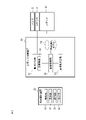
- FIG. 2 is a block diagram showing the functional configurations of the robot control device 20 and the teaching operation device 30.
- the robot control device 20 includes a motion control unit 21, an image processing unit 22, and a coordinate system determination unit 23. Further, the robot control device 20 stores the feature extraction model 24 in the storage unit.
- the motion control unit 21 executes motion control of the robot 10. More specifically, the motion control unit 21 interprets the motion command, calculates the position command for each axis motor of the robot 10, and executes the servo control of each axis motor in response to the position command. Performs position control of the control center (eg, tool tip point).
- the motion control unit 21 may further have a function of controlling the opening / closing motion of the hand 5.
- the image processing unit 22 is designated on the image from the image in which at least a part of the robot 10 is captured by using the feature extraction model 24 for detecting the image of the robot 10 and the position and posture information of the robot 10.
- the position in the three-dimensional space corresponding to the designated position is detected as a relative position with respect to the robot 10.
- the coordinate system determination unit 23 sets the control center for controlling the operation of the robot 10 at the detected position in the three-dimensional space.
- the robot 10 may further be equipped with a force sensor 3 for executing force control.
- FIG. 2 shows a configuration example in which a force sensor 3 for detecting an external force applied to the tip of an arm is mounted on the robot 10.
- the force sensor 3 is arranged between the hand 5 and the flange 11 as shown in FIG. 10, for example.
- the motion control unit 21 further includes a force control unit 25 that executes force control using the force sensor 3.
- the teaching operation device 30 includes a control unit 31 that controls teaching input operations and various setting functions, a display unit 32 that displays operation screens related to teaching input operations and various setting functions, and an operation unit 33 for performing various input operations. And have.
- the display unit 32 has, for example, a liquid crystal display as a display device.
- the operation unit 33 may be composed of software keys using a touch panel as an example.
- the teaching operation device 30 further includes a camera 34 as an image pickup device.
- the camera may be, for example, a two-dimensional camera that captures a two-dimensional image, or may be a three-dimensional camera that acquires a three-dimensional position of an object by, for example, a stereo method.
- the image taken by the camera 34 is displayed on the display unit 32.
- the user controls the operation of the robot 10 by designating the position of the control center on the image obtained by photographing the robot 10 using the camera 34 of the teaching operation device 30.
- the control center and coordinate system can be set.
- the teaching operation device 30 displays the captured image on the display unit 32 under the control of the image processing unit 22 of the robot control device 20, and then receives the above-mentioned designated operation via the operation unit 33. Works like.
- FIG. 3 is a flowchart showing the flow of the control center and the coordinate system setting process.
- the control center and coordinate system setting processes are mainly executed under the control of the CPU of the robot control device 20, and the teaching operation device 30 is used as an operation terminal for the user to perform various operation inputs.
- the user captures two images of a part (or detection marker) of the robot 10 from different directions (step S1).
- the two captured images are referred to as a camera image M1 and a camera image M2.
- the camera image M1 is, for example, an image as shown in FIG. In the example of the camera image M1 of FIG. 4, the robot arm tip portion, the flange 11, and the hand 5 to which the three detection markers C1-C3 are attached are shown.
- the camera image M2 is an image of the object to be photographed of the camera image M1 taken from another angle.
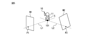
- the shooting directions of the camera image M1 and the camera image M2 with respect to the tip of the arm as the shooting target are as shown in FIG. 5, for example.
- the user specifies a position to be the control center for controlling the operation of the robot 10 in each of the camera image M1 and the camera image M2 (step S2).
- As an operation for the user to specify the position on the image there may be an operation of tapping on the touch panel or an example of specifying by operating another pointing device.
- the user designates the center positions of the plurality of gripping claws of the hand 5 as the positions desired to be the control center.
- the user specifies the center position of the gripping claw of the hand 5 in each of the camera images M1 and M2.
- the image processing unit 22 accepts such a designated operation via the teaching operation device 30.
- the positions designated by the user as the centers of the tips of the plurality of gripping claws of the hand 5 on the camera images M1 and M2 are designated positions P1 and P2, respectively.
- the image processing unit 22 uses a feature extraction model 24 (a detection marker or a 3D model of the robot 10) for extracting features on the image of the robot 10 to perform image processing in a three-dimensional space.
- the relative position between the designated position of the robot 10 and the robot 10 is detected (step S3).
- the detection markers C1-C3 are present at the tip of the arm of the robot 10
- the feature extraction model 24 information regarding the features and arrangement of the images of the detection markers C1-C3 is used.
- the appearance of the three detection markers C1-C3 and the visible detection markers differ depending on the viewing angle of the robot 10.
- the image processing unit 22 detects the three detection markers C1-C3 by performing image processing on each of the camera images M1 and M2, and analyzes the appearance of the three detection markers C1-C3 to analyze the appearance of the three detection markers C1-C3. It is specified from which direction each of M2 is imaged when viewed from the flange 11. Further, since a plurality of detection markers C1-C3 exist on each image and the interval between the plurality of detection markers C1-C3 is known from the feature extraction model 24, the image processing unit 22 may scale the image. (That is, the correspondence between the size on the image and the actual size) can be known.
- the image processing unit 22 grasps that the imaging direction with respect to the flange 11 for each of the camera images M1 and M2 is as shown in FIG. At this time, the image processing unit 22 also uses the current position / posture information of the robot 10. What can be seen from one camera image here is that the designated position on the image exists on the axis in the three-dimensional space.
- the axis line L1 is represented as the axis line L1 in which the position corresponding to the designated position P1 can exist in the three-dimensional space specified by the image processing for the camera image M1, and is specified by the image processing for the camera image M2.
- the axis line in which the position corresponding to the designated position P2 can exist in the dimensional space is represented as the axis line L2. That is, the designated position P1 is on the axis L1 in the three-dimensional space, and the designated position P2 is on the axis L2 in the three-dimensional space.
- the intersection 101 of the axis L1 and the axis L2 is the position in the three-dimensional space of the control center designated by the user.
- the image processing unit 22 specifies the position of the intersection 101. From the above, the position (relative position with respect to the robot 10) in the three-dimensional space corresponding to the designated position on the image can be obtained (step S3).
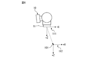
- a flange coordinate system 111 having an origin at the center position of the flange surface is preset.
- the coordinate system determination unit 23 sets the tool coordinate system 112 by translating (translating) the origin of the known flange coordinate system 111 to the control center (intersection point 101) specified in step S3. ..
- step S1 a method of obtaining the relative position between the designated position on the image and the robot 10 by pattern matching using the 3D model of the robot 10 as the feature extraction model 24.
- the user is made to take two images including a part of the robot 10 from different directions (step S1).
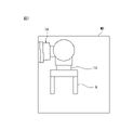
- one of the images to be captured is a camera image M3 including two links on the tip side of the arm and a hand 5 as shown in FIG. 7.
- the other image is an image as if the object to be imaged in FIG. 7 was captured from another angle.
- the user specifies the position to be the control center on each image (step S2).
- the image processing unit 22 obtains a relative position between the designated position in each image and the robot 10 (step S3). This will be described in detail.
- the image processing unit 22 performs image detection using a model of the tip of the arm (hereinafter referred to as a robot model) among the 3D models of the robot 10. .
- the image processing unit 22 specifies the posture of the arm tip portion reflected in the image by applying the face recognition technique using the information on the shape and arrangement of the flat portion, the convex portion, and the concave portion of the arm tip portion.
- the shooting direction of the image may be specified based on the current position / posture information of the robot 10.
- the image processing unit 22 extracts a contour from the image by an edge detection method, performs pattern matching with the contour of the robot model (the contour of the arm tip), and determines the posture of the arm tip reflected in the image. It may be specified and the shooting direction of the image may be specified based on the current position / posture information of the robot 10.
- the position of the designated position in the three-dimensional space is specified as the intersection of the axes in the shooting direction obtained from the two images (that is, the relative position between the designated position and the robot 10 is obtained) (step S3). ..
- the coordinate system determination unit 23 sets the tool coordinate system by translating the flange coordinate system to the specified control center (intersection point) (step S4).
- control center and coordinate system setting process the user only performs an operation of photographing the robot 10 with the camera 34 of the teaching operation device 30 and an operation of designating a position desired to be the control center on the image.
- the control center and coordinate system settings can be completed. That is, it is possible to facilitate the setting operation of the control center and the coordinate system. With respect to the camera 34, it is not necessary to perform complicated work such as calibration.
- the above is an example of specifying the control center from two or more images, but it is also possible to specify the control center from one image.
- An example of specifying the position (relative position with respect to the robot 10) of the control center in the three-dimensional space from one image captured by the user will be described.
- the procedure below (A1) The user performs imaging under the restriction that the tip of the arm of the robot 10 is imaged from the side (along the Y-axis direction of the flange coordinate system).
- A2 The user specifies a position desired to be the control center on the image captured under such restrictions. In this case, as shown in FIG. 6, an image parallel to the XZ plane of the flange coordinate system 111 is captured.
- the image processing unit 22 recognizes the scale of the image from the intervals of the detection markers projected on the image, and sets the designated position on the image X with reference to the flange center (origin of the flange coordinate system) in the image. , Recognized as Z coordinate position.
- A4 Thereby, the position in the three-dimensional space corresponding to the designated position on the image is specified as the X and Z coordinate positions of the flange coordinate system.
- the following method may be used as a method for specifying the control center from one image. In this case, it is premised that the coordinate system to be controlled is set on the central axis of the flange coordinate system (that is, on the Z axis). The user captures an image including the flange 11.
- the image processing unit 22 receives an operation (for example, a touch and slide operation) of shifting the flange coordinate system in the Z-axis direction on the image including the portion of the flange 11 of the robot 10. In this case, the image processing unit 22 may superimpose and display an image representing the flange coordinate system on the image.
- the image processing unit 22 specifies the shift amount on the Z axis of the flange coordinate system by the user operation.
- the coordinate system determination unit 23 translates the flange coordinate system to the position of the control center specified in this way and sets the tool coordinate system.
- the robot control device 20 may automatically specify the control center position on the captured image. For example, (1) a predetermined position (for example, the center position) on the captured image is set as a designated position, and (2) a sensor (acceleration sensor, gyro) that detects the position of the camera 34 in the three-dimensional space on the teaching operation device 30. A sensor or the like) is mounted, and the starting point (designated positions P1 and P2) when the axes L1 and L2 in FIG. 5 are set is set to the position detected by the sensor (in this case, the teaching operation device 30 is the captured image. (Providing the robot control device 20 with the position information of the camera 34 when the image is taken) may be adopted.
- the columnar fitting is an operation of inserting a columnar work W1 gripped by the hand 5 into a hole formed in the work W2.
- the user sets the control center at the center of the tip surface of the work W1 and sets the tool coordinate system with the control center as the origin.
- the robot control device 20 controls the robot 10 so that the work W1 is moved until the origin (control center) of the tool coordinate system moves along the central axis of the hole and reaches the bottom of the hole.
- FIG. 9 shows a situation in which control centers 201, 202, and 203 are set for each of three types of workpieces W11, W12, and W13 having different lengths.
- a tool coordinate system (see the force control coordinate system 113 in FIG. 12 for reference) is set for each of the control centers 201-203 with the vertical downward direction in the Z-axis direction.
- the force sensor 3 is, for example, a 6-axis force sensor that outputs a load of 3 axes (XYZ) and a moment around each axis as detection values.
- the force sensor 3 detects the force and the moment applied to the fitting work W21 during the fitting operation.
- the robot control device 20 motion control unit 21 and force control unit 25
- the force control unit 25 uses the control center set as described above as a control point for force control (a reference point for calculating a moment or the like).
- the coordinate system determining unit 23 translates the flange coordinate system to this control point and sets it as a force control coordinate system (see the force control coordinate system 113 in FIG. 12).
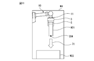
- the image processing unit 22 may be configured to accept the setting of the pressing direction as a parameter related to force control via the image. Two examples of setting the pressing direction as the force control parameter via an image will be described with reference to FIGS. 11 and 12.
- the image M4 displays the arm tip side of the robot 10, the force sensor 3, the hand 5, the mating work W21, the work W22, and the control center 204 set by the user.
- the image processing unit 22 displays, for example, an arrow 71 along the Z-axis direction (vertically downward) as an image in order to assist the user in setting the pressing direction of the force control. If the arrow 71 matches the desired pressing direction, the user can select, for example, by tapping the image of the arrow 71.
- the image processing unit 22 accepts such a selection operation by the user.
- the image processing unit 22 may display an image of three arrows in the X, Y, and Z directions on the image M4 and allow the user to select a desired pressing direction.
- the image M5 displays the arm tip side of the robot 10, the force sensor 3, the hand 5, the mating work W21, the work W22, and the control center 204 set by the user.
- the image processing unit 22 accepts an operation on such an image M5 in which the user specifies the pressing direction by a flick operation or draws an arrow (arrow 72 in FIG. 12) by freehand on the image. Then, the image processing unit 22 has the direction of the flick operation or the direction of the axis closest to the direction of the arrow 72 drawn as an image among the axes of the force control coordinate system 113 set at the tip of the fitting work W21. Is selected as the pressing direction. In the case of the example of FIG. 12, the Z-axis direction is selected as the pressing direction.
- the force control unit 25 executes force control with respect to the pressing direction specified as described above.
- FIG. 13 is a diagram illustrating an example in which the image processing unit 22 sets a range in the depth direction (range in the traveling direction of the tool) in which force control can be executed as a parameter related to force control on the image.
- the image M6 shown in FIG. 13 the arm tip side of the robot 10, the force sensor 3, the hand 5, the fitting work W21, the work W22, and the control center 204 set by the user are displayed.
- the image processing unit 22 can operate in the depth direction (Z) by force control by drawing, for example, a freehand image of a rectangular frame (rectangular frame 73 in FIG. 13) on such an image M6. Accepts operations to set the range (in the axial direction).
- the force control unit 25 of the robot control device 20 applies force control when the control center (control point) 204 is within the range of the rectangular frame 73 in the Z-axis direction.
- the designation of this rectangular frame can also be expressed as the designation of an area where force control can be executed.
- the hand 150 shown in FIG. 14 includes a plurality of chuck hands 151-153.
- the chuck hands 151, 152, and 153 grip the workpieces W31, W32, and W33, respectively. It is assumed that the control centers 211, 212, and 213 are set for each of the works W31 to W33 by the above-mentioned method.
- Set the tool coordinate system by the following procedure.
- a 3D camera capable of detecting the three-dimensional position of the object is used as the camera 34.
- the image processing unit 22 detects a plane as a work tip surface for each of the work W31, W32, and W33 from the image including the hand 150.
- a plane detection method by a three-dimensional Hough transform can be used as a method for detecting a plane by image processing.
- the tip surfaces W31a, W32a, and W33a of the work W31, W32, and W33 are detected, respectively.
- the coordinate system determination unit 23 obtains a rotation matrix in the normal direction of each tip surface W31a, W32a, W33a with respect to the Z direction of the flange coordinate system.
- the coordinate system determination unit 23 translates the origin of the flange coordinate system to each of the control centers 211, 212, and 213, and multiplies the rotation matrix obtained for each tip surface. Then, the tool coordinate system is set for each of the control centers 211, 212, and 213.
- the coordinate system determination unit 23 has tool coordinates at a point (for example, the center) on the work tip surface detected by the above (B1).
- the origin of the system may be set, and the tool coordinate system may be automatically set so that the normal direction of the work tip surface and the Z-axis direction of the tool coordinate system match.
- the distribution of functions in the robot system shown in the block diagram of FIG. 2 is an example, and various modifications can be made.
- Each functional block in the functional block diagram of the robot control device 20 shown in FIG. 2 may be realized by the CPU of the robot control device 20 executing various hardware stored in the storage device, or ASIC. It may be realized by a configuration mainly composed of hardware such as (Application Specific Integrated Circuit).
- the program that executes the control center and coordinate system setting processing in the above-described embodiment is a computer-readable recording medium (for example, a semiconductor memory such as ROM, EEPROM, flash memory, a magnetic recording medium, a CD-ROM, or a DVD-. It can be recorded on an optical disk such as ROM).
- a computer-readable recording medium for example, a semiconductor memory such as ROM, EEPROM, flash memory, a magnetic recording medium, a CD-ROM, or a DVD-. It can be recorded on an optical disk such as ROM).
Landscapes
- Engineering & Computer Science (AREA)
- Robotics (AREA)
- Mechanical Engineering (AREA)
- Human Computer Interaction (AREA)
- Computer Vision & Pattern Recognition (AREA)
- Physics & Mathematics (AREA)
- General Physics & Mathematics (AREA)
- Theoretical Computer Science (AREA)
- Manipulator (AREA)
Priority Applications (4)
| Application Number | Priority Date | Filing Date | Title |
|---|---|---|---|
| US18/033,211 US12403594B2 (en) | 2020-11-02 | 2021-10-27 | Robot control device, and robot system |
| DE112021004632.2T DE112021004632T5 (de) | 2020-11-02 | 2021-10-27 | Robotersteuerungsvorrichtung und robotersystem |
| CN202180072428.5A CN116419827A (zh) | 2020-11-02 | 2021-10-27 | 机器人控制装置以及机器人系统 |
| JP2022559210A JPWO2022092168A1 (https=) | 2020-11-02 | 2021-10-27 |
Applications Claiming Priority (2)
| Application Number | Priority Date | Filing Date | Title |
|---|---|---|---|
| JP2020183920 | 2020-11-02 | ||
| JP2020-183920 | 2020-11-02 |
Publications (1)
| Publication Number | Publication Date |
|---|---|
| WO2022092168A1 true WO2022092168A1 (ja) | 2022-05-05 |
Family
ID=81382643
Family Applications (1)
| Application Number | Title | Priority Date | Filing Date |
|---|---|---|---|
| PCT/JP2021/039711 Ceased WO2022092168A1 (ja) | 2020-11-02 | 2021-10-27 | ロボット制御装置及びロボットシステム |
Country Status (5)
| Country | Link |
|---|---|
| US (1) | US12403594B2 (https=) |
| JP (1) | JPWO2022092168A1 (https=) |
| CN (1) | CN116419827A (https=) |
| DE (1) | DE112021004632T5 (https=) |
| WO (1) | WO2022092168A1 (https=) |
Cited By (1)
| Publication number | Priority date | Publication date | Assignee | Title |
|---|---|---|---|---|
| JP7835824B1 (ja) * | 2024-11-01 | 2026-03-25 | 株式会社ダイヘン | ロボットシステム |
Families Citing this family (2)
| Publication number | Priority date | Publication date | Assignee | Title |
|---|---|---|---|---|
| DE102022213568B3 (de) | 2022-12-13 | 2024-02-29 | Kuka Deutschland Gmbh | Kalibrieren einer Steuerung |
| DE102023133636B3 (de) | 2023-12-01 | 2025-02-06 | IGZ Ingenieurgesellschaft für logistische Informationssysteme mbH | Robotersystem und Verfahren mit Messung der Greifabweichung |
Citations (4)
| Publication number | Priority date | Publication date | Assignee | Title |
|---|---|---|---|---|
| JP2004009209A (ja) * | 2002-06-06 | 2004-01-15 | Yaskawa Electric Corp | ロボットの教示装置 |
| JP2005111618A (ja) * | 2003-10-08 | 2005-04-28 | Fanuc Ltd | ロボットの手動送り装置 |
| JP2020055075A (ja) * | 2018-10-02 | 2020-04-09 | ファナック株式会社 | 拡張現実と複合現実を用いたロボット制御装置及び表示装置 |
| JP2020075325A (ja) * | 2018-11-08 | 2020-05-21 | 株式会社Ihi | ツールセンターポイントの設定方法及び設定装置 |
Family Cites Families (15)
| Publication number | Priority date | Publication date | Assignee | Title |
|---|---|---|---|---|
| JPH03251378A (ja) | 1990-02-28 | 1991-11-08 | Fanuc Ltd | ロボットのキャリブレーション方式 |
| DE10305384A1 (de) | 2003-02-11 | 2004-08-26 | Kuka Roboter Gmbh | Verfahren und Vorrichtung zur Visualisierung rechnergestützter Informationen |
| JP4191080B2 (ja) * | 2004-04-07 | 2008-12-03 | ファナック株式会社 | 計測装置 |
| US20090118864A1 (en) * | 2007-11-01 | 2009-05-07 | Bryce Eldridge | Method and system for finding a tool center point for a robot using an external camera |
| JP2013184257A (ja) * | 2012-03-08 | 2013-09-19 | Sony Corp | ロボット装置及びロボット装置の制御方法、並びにコンピューター・プログラム |
| JP6489776B2 (ja) | 2013-08-28 | 2019-03-27 | キヤノン株式会社 | 座標系校正方法、ロボットシステム、プログラム及び記録媒体 |
| JP2016187844A (ja) * | 2015-03-30 | 2016-11-04 | セイコーエプソン株式会社 | ロボット、ロボット制御装置およびロボットシステム |
| US10730180B2 (en) * | 2015-05-29 | 2020-08-04 | Abb Schweiz Ag | User interface for a teleoperated robot |
| CN105729468B (zh) * | 2016-01-27 | 2018-01-09 | 浙江大学 | 一种基于多深度摄像机增强的机器人工作台 |
| JP2017170571A (ja) * | 2016-03-24 | 2017-09-28 | セイコーエプソン株式会社 | ロボット、ロボット制御装置、及びロボットシステム |
| US10363661B2 (en) * | 2016-07-27 | 2019-07-30 | Seiko Epson Corporation | Control device, robot, and robot system |
| JP2018069361A (ja) * | 2016-10-27 | 2018-05-10 | セイコーエプソン株式会社 | 力制御座標軸設定装置、ロボットおよび力制御座標軸設定方法 |
| JP6445092B2 (ja) * | 2017-05-31 | 2018-12-26 | ファナック株式会社 | ロボットの教示のための情報を表示するロボットシステム |
| JP7124440B2 (ja) * | 2018-05-23 | 2022-08-24 | セイコーエプソン株式会社 | ロボット制御装置およびロボットシステム |
| JP6740288B2 (ja) * | 2018-07-13 | 2020-08-12 | ファナック株式会社 | 物体検査装置、物体検査システム、及び検査位置を調整する方法 |
-
2021
- 2021-10-27 WO PCT/JP2021/039711 patent/WO2022092168A1/ja not_active Ceased
- 2021-10-27 JP JP2022559210A patent/JPWO2022092168A1/ja active Pending
- 2021-10-27 US US18/033,211 patent/US12403594B2/en active Active
- 2021-10-27 DE DE112021004632.2T patent/DE112021004632T5/de active Pending
- 2021-10-27 CN CN202180072428.5A patent/CN116419827A/zh active Pending
Patent Citations (4)
| Publication number | Priority date | Publication date | Assignee | Title |
|---|---|---|---|---|
| JP2004009209A (ja) * | 2002-06-06 | 2004-01-15 | Yaskawa Electric Corp | ロボットの教示装置 |
| JP2005111618A (ja) * | 2003-10-08 | 2005-04-28 | Fanuc Ltd | ロボットの手動送り装置 |
| JP2020055075A (ja) * | 2018-10-02 | 2020-04-09 | ファナック株式会社 | 拡張現実と複合現実を用いたロボット制御装置及び表示装置 |
| JP2020075325A (ja) * | 2018-11-08 | 2020-05-21 | 株式会社Ihi | ツールセンターポイントの設定方法及び設定装置 |
Cited By (1)
| Publication number | Priority date | Publication date | Assignee | Title |
|---|---|---|---|---|
| JP7835824B1 (ja) * | 2024-11-01 | 2026-03-25 | 株式会社ダイヘン | ロボットシステム |
Also Published As
| Publication number | Publication date |
|---|---|
| US12403594B2 (en) | 2025-09-02 |
| DE112021004632T5 (de) | 2023-06-29 |
| JPWO2022092168A1 (https=) | 2022-05-05 |
| TW202218836A (zh) | 2022-05-16 |
| CN116419827A (zh) | 2023-07-11 |
| US20230321823A1 (en) | 2023-10-12 |
Similar Documents
| Publication | Publication Date | Title |
|---|---|---|
| TWI672206B (zh) | 機械手臂非接觸式工具中心點校正裝置及其方法以及具有校正功能的機械手臂系統 | |
| JP7207851B2 (ja) | 制御方法、ロボットシステム、物品の製造方法、プログラム及び記録媒体 | |
| JP5471355B2 (ja) | 3次元視覚センサ | |
| CN109397282B (zh) | 机械手臂加工方法、系统及计算机可读取纪录媒体 | |
| JP3946711B2 (ja) | ロボットシステム | |
| WO2022092168A1 (ja) | ロボット制御装置及びロボットシステム | |
| CN106217372A (zh) | 机器人、机器人控制装置以及机器人系统 | |
| JP2018167334A (ja) | 教示装置および教示方法 | |
| JP2018126835A (ja) | ロボットの教示方法、ロボットシステム、プログラム及び記録媒体 | |
| JP2011112402A (ja) | 3次元視覚センサにおける計測有効領域の表示方法および3次元視覚センサ | |
| WO2009113339A1 (ja) | 動作教示システム及び動作教示方法 | |
| CN106003020A (zh) | 机器人、机器人控制装置以及机器人系统 | |
| CN116472551B (zh) | 调整参数的装置、机器人系统、方法以及计算机程序产品 | |
| JP6885856B2 (ja) | ロボットシステムおよびキャリブレーション方法 | |
| JP2018051634A (ja) | ロボット制御装置、ロボット、ロボットシステムおよび姿勢特定装置 | |
| JP7323993B2 (ja) | 制御装置、ロボットシステム、制御装置の動作方法及びプログラム | |
| CN116323115A (zh) | 控制装置、机器人臂系统以及机器人臂装置的控制方法 | |
| CN117754589A (zh) | 标定方法、标定装置、计算机设备和计算机可读存储介质 | |
| JP7658148B2 (ja) | ロボット画像の表示方法、コンピュータープログラム、及び、ロボット画像の表示システム | |
| CN115397634B (zh) | 取得机器人的控制坐标系中的视觉传感器的位置的装置、机器人系统、方法以及计算机程序 | |
| US12311541B2 (en) | Generation method, computer program, and generation system | |
| JP2022152845A (ja) | ロボット制御用のキャリブレーション装置 | |
| JPH0847881A (ja) | ロボットの遠隔操作方法 | |
| WO2022176928A1 (ja) | 教示装置 | |
| TWI916434B (zh) | 機器人控制裝置及機器人系統 |
Legal Events
| Date | Code | Title | Description |
|---|---|---|---|
| 121 | Ep: the epo has been informed by wipo that ep was designated in this application |
Ref document number: 21886285 Country of ref document: EP Kind code of ref document: A1 |
|
| ENP | Entry into the national phase |
Ref document number: 2022559210 Country of ref document: JP Kind code of ref document: A |
|
| 122 | Ep: pct application non-entry in european phase |
Ref document number: 21886285 Country of ref document: EP Kind code of ref document: A1 |
|
| WWG | Wipo information: grant in national office |
Ref document number: 18033211 Country of ref document: US |