WO2022092030A1 - 植物栽培装置及び方法 - Google Patents
植物栽培装置及び方法 Download PDFInfo
- Publication number
- WO2022092030A1 WO2022092030A1 PCT/JP2021/039317 JP2021039317W WO2022092030A1 WO 2022092030 A1 WO2022092030 A1 WO 2022092030A1 JP 2021039317 W JP2021039317 W JP 2021039317W WO 2022092030 A1 WO2022092030 A1 WO 2022092030A1
- Authority
- WO
- WIPO (PCT)
- Prior art keywords
- cultivation
- lighting
- plant
- plant cultivation
- air
- Prior art date
Links
- 238000000034 method Methods 0.000 title description 10
- 241000196324 Embryophyta Species 0.000 claims description 134
- 238000005286 illumination Methods 0.000 claims description 36
- 238000009434 installation Methods 0.000 claims description 21
- 235000013311 vegetables Nutrition 0.000 claims description 19
- 238000007664 blowing Methods 0.000 claims description 13
- 230000001143 conditioned effect Effects 0.000 claims description 13
- 238000012546 transfer Methods 0.000 claims description 13
- 240000008415 Lactuca sativa Species 0.000 claims description 11
- 238000009423 ventilation Methods 0.000 claims description 9
- 235000003228 Lactuca sativa Nutrition 0.000 claims description 7
- 241000219193 Brassicaceae Species 0.000 claims description 5
- 238000012364 cultivation method Methods 0.000 claims description 4
- 235000012045 salad Nutrition 0.000 claims description 4
- 240000009088 Fragaria x ananassa Species 0.000 claims description 3
- 235000007688 Lycopersicon esculentum Nutrition 0.000 claims description 3
- 240000003768 Solanum lycopersicum Species 0.000 claims description 3
- 244000300264 Spinacia oleracea Species 0.000 claims description 3
- 235000009337 Spinacia oleracea Nutrition 0.000 claims description 3
- 235000013399 edible fruits Nutrition 0.000 claims description 3
- 241000555825 Clupeidae Species 0.000 claims description 2
- 235000004789 Rosa xanthina Nutrition 0.000 claims description 2
- 241000109329 Rosa xanthina Species 0.000 claims description 2
- 235000021384 green leafy vegetables Nutrition 0.000 claims description 2
- 235000019512 sardine Nutrition 0.000 claims description 2
- 235000021012 strawberries Nutrition 0.000 claims description 2
- 238000004378 air conditioning Methods 0.000 claims 1
- 239000007788 liquid Substances 0.000 description 21
- 239000003337 fertilizer Substances 0.000 description 14
- 210000000078 claw Anatomy 0.000 description 12
- 238000003306 harvesting Methods 0.000 description 8
- 230000001105 regulatory effect Effects 0.000 description 8
- 238000005259 measurement Methods 0.000 description 7
- 208000037824 growth disorder Diseases 0.000 description 5
- 230000007246 mechanism Effects 0.000 description 4
- XLYOFNOQVPJJNP-UHFFFAOYSA-N water Substances O XLYOFNOQVPJJNP-UHFFFAOYSA-N 0.000 description 4
- 235000015802 Lactuca sativa var crispa Nutrition 0.000 description 3
- 240000004201 Lactuca sativa var. crispa Species 0.000 description 3
- 238000009833 condensation Methods 0.000 description 3
- 230000005494 condensation Effects 0.000 description 3
- 238000007796 conventional method Methods 0.000 description 3
- 230000003028 elevating effect Effects 0.000 description 3
- 230000001965 increasing effect Effects 0.000 description 3
- 235000015097 nutrients Nutrition 0.000 description 3
- CURLTUGMZLYLDI-UHFFFAOYSA-N Carbon dioxide Chemical compound O=C=O CURLTUGMZLYLDI-UHFFFAOYSA-N 0.000 description 2
- 230000008859 change Effects 0.000 description 2
- 230000000694 effects Effects 0.000 description 2
- 230000004907 flux Effects 0.000 description 2
- 238000009331 sowing Methods 0.000 description 2
- 244000291564 Allium cepa Species 0.000 description 1
- 235000002732 Allium cepa var. cepa Nutrition 0.000 description 1
- 241000219317 Amaranthaceae Species 0.000 description 1
- 241000208838 Asteraceae Species 0.000 description 1
- 244000233513 Brassica perviridis Species 0.000 description 1
- 235000010149 Brassica rapa subsp chinensis Nutrition 0.000 description 1
- 244000221633 Brassica rapa subsp chinensis Species 0.000 description 1
- 244000024675 Eruca sativa Species 0.000 description 1
- 235000014755 Eruca sativa Nutrition 0.000 description 1
- 235000016623 Fragaria vesca Nutrition 0.000 description 1
- 235000011363 Fragaria x ananassa Nutrition 0.000 description 1
- 241000208292 Solanaceae Species 0.000 description 1
- 244000061458 Solanum melongena Species 0.000 description 1
- 235000002597 Solanum melongena Nutrition 0.000 description 1
- 238000010521 absorption reaction Methods 0.000 description 1
- 230000002411 adverse Effects 0.000 description 1
- 235000000183 arugula Nutrition 0.000 description 1
- 238000009529 body temperature measurement Methods 0.000 description 1
- 229910002092 carbon dioxide Inorganic materials 0.000 description 1
- 239000001569 carbon dioxide Substances 0.000 description 1
- 230000000052 comparative effect Effects 0.000 description 1
- 238000013461 design Methods 0.000 description 1
- 238000011156 evaluation Methods 0.000 description 1
- 239000000203 mixture Substances 0.000 description 1
- 238000012986 modification Methods 0.000 description 1
- 230000004048 modification Effects 0.000 description 1
- 230000029553 photosynthesis Effects 0.000 description 1
- 238000010672 photosynthesis Methods 0.000 description 1
- 230000000243 photosynthetic effect Effects 0.000 description 1
- 210000004767 rumen Anatomy 0.000 description 1
- 230000007480 spreading Effects 0.000 description 1
Images


Classifications
-
- A—HUMAN NECESSITIES
- A01—AGRICULTURE; FORESTRY; ANIMAL HUSBANDRY; HUNTING; TRAPPING; FISHING
- A01G—HORTICULTURE; CULTIVATION OF VEGETABLES, FLOWERS, RICE, FRUIT, VINES, HOPS OR SEAWEED; FORESTRY; WATERING
- A01G31/00—Soilless cultivation, e.g. hydroponics
- A01G31/02—Special apparatus therefor
- A01G31/04—Hydroponic culture on conveyors
-
- A—HUMAN NECESSITIES
- A01—AGRICULTURE; FORESTRY; ANIMAL HUSBANDRY; HUNTING; TRAPPING; FISHING
- A01G—HORTICULTURE; CULTIVATION OF VEGETABLES, FLOWERS, RICE, FRUIT, VINES, HOPS OR SEAWEED; FORESTRY; WATERING
- A01G9/00—Cultivation in receptacles, forcing-frames or greenhouses; Edging for beds, lawn or the like
- A01G9/24—Devices or systems for heating, ventilating, regulating temperature, illuminating, or watering, in greenhouses, forcing-frames, or the like
- A01G9/246—Air-conditioning systems
-
- A—HUMAN NECESSITIES
- A01—AGRICULTURE; FORESTRY; ANIMAL HUSBANDRY; HUNTING; TRAPPING; FISHING
- A01G—HORTICULTURE; CULTIVATION OF VEGETABLES, FLOWERS, RICE, FRUIT, VINES, HOPS OR SEAWEED; FORESTRY; WATERING
- A01G31/00—Soilless cultivation, e.g. hydroponics
- A01G31/02—Special apparatus therefor
- A01G31/04—Hydroponic culture on conveyors
- A01G31/042—Hydroponic culture on conveyors with containers travelling on a belt or the like, or conveyed by chains
-
- A—HUMAN NECESSITIES
- A01—AGRICULTURE; FORESTRY; ANIMAL HUSBANDRY; HUNTING; TRAPPING; FISHING
- A01G—HORTICULTURE; CULTIVATION OF VEGETABLES, FLOWERS, RICE, FRUIT, VINES, HOPS OR SEAWEED; FORESTRY; WATERING
- A01G31/00—Soilless cultivation, e.g. hydroponics
- A01G31/02—Special apparatus therefor
- A01G31/04—Hydroponic culture on conveyors
- A01G31/045—Hydroponic culture on conveyors with containers guided along a rail
-
- A—HUMAN NECESSITIES
- A01—AGRICULTURE; FORESTRY; ANIMAL HUSBANDRY; HUNTING; TRAPPING; FISHING
- A01G—HORTICULTURE; CULTIVATION OF VEGETABLES, FLOWERS, RICE, FRUIT, VINES, HOPS OR SEAWEED; FORESTRY; WATERING
- A01G31/00—Soilless cultivation, e.g. hydroponics
- A01G31/02—Special apparatus therefor
- A01G31/06—Hydroponic culture on racks or in stacked containers
-
- A—HUMAN NECESSITIES
- A01—AGRICULTURE; FORESTRY; ANIMAL HUSBANDRY; HUNTING; TRAPPING; FISHING
- A01G—HORTICULTURE; CULTIVATION OF VEGETABLES, FLOWERS, RICE, FRUIT, VINES, HOPS OR SEAWEED; FORESTRY; WATERING
- A01G9/00—Cultivation in receptacles, forcing-frames or greenhouses; Edging for beds, lawn or the like
- A01G9/04—Flower-pot saucers
- A01G9/047—Channels or gutters, e.g. for hydroponics
-
- Y—GENERAL TAGGING OF NEW TECHNOLOGICAL DEVELOPMENTS; GENERAL TAGGING OF CROSS-SECTIONAL TECHNOLOGIES SPANNING OVER SEVERAL SECTIONS OF THE IPC; TECHNICAL SUBJECTS COVERED BY FORMER USPC CROSS-REFERENCE ART COLLECTIONS [XRACs] AND DIGESTS
- Y02—TECHNOLOGIES OR APPLICATIONS FOR MITIGATION OR ADAPTATION AGAINST CLIMATE CHANGE
- Y02A—TECHNOLOGIES FOR ADAPTATION TO CLIMATE CHANGE
- Y02A40/00—Adaptation technologies in agriculture, forestry, livestock or agroalimentary production
- Y02A40/10—Adaptation technologies in agriculture, forestry, livestock or agroalimentary production in agriculture
- Y02A40/25—Greenhouse technology, e.g. cooling systems therefor
-
- Y—GENERAL TAGGING OF NEW TECHNOLOGICAL DEVELOPMENTS; GENERAL TAGGING OF CROSS-SECTIONAL TECHNOLOGIES SPANNING OVER SEVERAL SECTIONS OF THE IPC; TECHNICAL SUBJECTS COVERED BY FORMER USPC CROSS-REFERENCE ART COLLECTIONS [XRACs] AND DIGESTS
- Y02—TECHNOLOGIES OR APPLICATIONS FOR MITIGATION OR ADAPTATION AGAINST CLIMATE CHANGE
- Y02P—CLIMATE CHANGE MITIGATION TECHNOLOGIES IN THE PRODUCTION OR PROCESSING OF GOODS
- Y02P60/00—Technologies relating to agriculture, livestock or agroalimentary industries
- Y02P60/20—Reduction of greenhouse gas [GHG] emissions in agriculture, e.g. CO2
- Y02P60/21—Dinitrogen oxide [N2O], e.g. using aquaponics, hydroponics or efficiency measures
Definitions
- the present invention relates to an apparatus and a method for cultivating a plant.
- Patent Document 1 describes an device in which transport units for cultivation beds are installed in multiple stages above and below, and the cultivation beds are sequentially moved.
- Patent Document 1 a substantially rectangular illuminated air blower panel is arranged so as to cover the upper part of a plurality of cultivation beds in each transport unit, and air is blown toward the plant from a blower pipe or a blower provided in the illuminated air blower panel ( 0016, 0020 paragraphs of the patent document, FIG. 2).
- Patent Document 2 describes a plant cultivation device in which nursery shelves are arranged in multiple stages above and below.
- a back panel is provided behind the nursery space between the nursery shelves, a vent is provided in the back panel, and an air fan is installed in the vent. By operating the air fan, airflow is supplied to the nursery space through the vent.
- Patent Document 2 since the airflow flows from the rear to the front in the nursery space, it is difficult for the airflow to enter between adjacent cultivation beds on the same surface.
- Another object of the present invention is to provide, in one aspect, a plant cultivation device and a method in which the influence of shading of lighting by a blowout duct for sending an air flow is small.
- the present invention has the following gist.
- Equation (1) y: Lighting installation interval [cm], x: Height from the top surface of the cultivation bed to the lighting [cm], ⁇ : Half-value angle of lighting 2 ⁇ [°] means half-value.
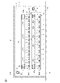
- the transport device 10 is provided so that the cultivation bed 4 is transported from the left side to the right side of FIG. 1 on the upper side and from the right side to the left side of FIG. 1 on the lower side.
- the transport device 10 is arranged on one end side and the other end side in the longitudinal direction of the cultivation bed 4, respectively.
- the transport device 10 may be arranged from one end side to the other end side in the longitudinal direction of the cultivation bed 4, or may be arranged from the other end side toward one end side.
- the planting hole 6 penetrates the cultivation plate 5. Seedlings (not shown) are inserted into the planting hole 6 from above. The seedlings are inserted into the planting hole 6 so that the roots of the seedlings are in contact with the liquid fertilizer flowing along the bottom surface of the cultivation bed 4.
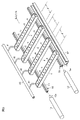
- the claw 12 is attached to the rod 11 so as to be tiltable by the shaft pin 14.
- the claw 12 is in a posture of protruding from the upper surface of the rod 11 due to the weight on the lower side of the shaft pin 14.
- the distance D between the transport portions on the lower stage side is larger than the distance D between the transport portions on the upper stage side. This is because plants are growing on the lower side than on the upper side.
- the intake air volume of the blower 25 has a capacity of about three times the discharge air volume of the air conditioner 20.
- the space provided on the bottom surface of the transport device 10 is common to the space of the transport section, and most of the adjusted air passes through the bottom surface of the transport section.
- the water evaporated from the plant does not stay between the leaves of the plant, and it becomes easy to suppress the chip burn.
- it exfoliates the foliar boundary layer to improve the absorption of carbon dioxide in plants.
- the space does not mean that the cultivation beds 4 are arranged at intervals, but the regulated air passes between the cultivation beds 4 and reaches below the cultivation beds 4. It means that it is a space that can be used.
- a blower 25 for sending conditioned air into the outlet duct 23 is provided on one end side (left end side in FIG. 1) of each outlet duct 23.
- the outlet duct 23 and the outlet duct 24 may allow the adjusted air to flow in the same direction as each other, but by allowing the adjusted air to flow in the opposite directions to each other, the air at a distant position in the cultivation room can be used as a blower. By sending in and creating airflows in opposite directions in the cultivation room, the air in the cultivation room does not stay, and the temperature uniformity of the entire system can be improved. It is preferable to make it flow.
- the lighting 28 of the present invention is a line light source in this embodiment.
- the light source of the illumination 28 is a line light source composed of COB type LEDs that are long and integrated in a linear shape, even if it is a line light source composed of LED chips forming tens to hundreds of point light sources. It doesn't matter if there is one.
- a plurality of light bulb-shaped lights may be arranged in series to form a line light source, or a line light source may be configured to have a plurality of rows in which a plurality of light sources are arranged in a line.
- the shape of the light source is not particularly limited, but it is easy to install it in a position that does not interfere with the outlet ducts 23 and 24, and by minimizing the height, the height of the entire device can be suppressed, so it has a rod-like shape. Is preferable.
- the illumination 28 is arranged so as to extend from one end side to the other end side of the transport portion. Further, at least a part of the lighting is arranged between the outlet ducts 23 or 24.
- blowout duct 23 and / or 24 is partially or wholly installed below the height of the lower surface of the illumination 28 and outside the orientation range of the half-value angle 2 ⁇ of the illumination 28.
- the blowout duct 23 and / or 24 is partially or wholly installed below the height of the lower surface of the illumination 28 and outside the orientation range of the half-value angle 2 ⁇ of the illumination 28.
- the lighting 28 is installed in parallel with the outlet ducts 23 and 24, and on the upper side, the lighting 28 is provided between the outlet ducts 23 and a total of four outside the outlet ducts 23. On the lower side as well, the lighting 28 is provided between the outlet ducts 24 and outside the outlet ducts 24 in a total of four rows.
- Such a positional relationship between the lighting 28 and the lighting 28 and the outlet duct 23 or 24 is the same as that of the above-mentioned plant cultivation apparatus in which a space for passing an air flow below the cultivation bed is provided. It may be used in combination.
- LED lighting As the lighting 28, it is possible to widen the distance between the lights, so that a blowout duct can be installed between the lights, and as a result, the influence of shading by the blowout duct can be suppressed to a small extent.
- the height from the upper surface of the cultivation bed 4 to the lighting is preferably in the range of y / tan ⁇ to 2y / tan ⁇ when the lighting installation interval is y and the half-value angle of the lighting is 2 ⁇ .
- 300 to 1500 mm is preferable, 400 to 1300 mm is more preferable, 500 to 1100 mm is further preferable, and 600 to 900 mm is particularly preferable.
- the distribution of PPFD on the cultivation surface can be made uniform while maintaining the lighting efficiency.
- the installation range of the outlet ducts 23 and 24 is outside the light distribution range of the half-value angle 2 ⁇ of the lighting.
- the lighting 28 is preferably LED lighting.
- the installation range of the outlet duct By setting the installation range of the outlet duct to the outside of the light distribution range of the half-value angle 2 ⁇ of the lighting, the irradiation light and the adjusted air can be uniformly supplied to the plant body, and the light distribution is uniform throughout the system. , Temperature distribution, humidity distribution can be obtained. Furthermore, the width and depth of the system can be set longer than before. As a result of uniform temperature distribution and humidity distribution, a homogeneous and high-quality plant can be obtained.
- the effective width (a) above the light source portion of the illumination is from the outer surface of the cover on the irradiation surface side of the illumination to the mounting position of the illumination.
- the cross-sectional area (S) is the total area of the cross-sectional areas of the plurality of outlet ducts per location when a plurality of outlet ducts are installed at each location of the outlet ducts. .. When there is no cover on the irradiation surface side, the distance from the light source portion of the illumination to the mounting position of the illumination is defined as the effective width (a).
- Equation (2) S: cross-sectional area of the outlet duct [cm 2 ], a: effective width above the light source of the lighting [cm], y: lighting installation interval [cm], ⁇ : half price of the lighting. It means the half value of the angle 2 ⁇ [°].
- the outlet duct can be installed at a position that does not block the light within the range of the half-value angle 2 ⁇ among the light emitted from the lighting.
- the diameter of the outlet duct is preferably 10 cm or more. 15 cm or more is more preferable, and 20 cm or more is further preferable. When it is at least the above lower limit value, it becomes easy to adjust the air volume.
- the value of the coefficient b is 0.433 or more when expressed by the following mathematical formula (4). It is preferably a certain thickness, more preferably 0.577 or more, and even more preferably 0.7 or more.
- the cultivation bed 4 in which the seedlings are planted is located on the entrance side (left side in FIG. 1) of the upper transport unit. It is arranged by human power or a carry-in machine, and is intermittently conveyed to the right in FIG. 1 by the upper transfer device 10.
- the cultivation bed 4 moves intermittently by one stroke of the piston rod 13a.
- the liquid fertilizer is supplied to each cultivation bed 4 via the liquid fertilizer supply pipe 40 and the nozzle 41.
- the difference in temperature on the cultivation bed of each stage of the plant cultivation apparatus of the present invention is within the range of ⁇ 1 ° C.
- the temperature difference on the cultivation bed can be reduced to a range of ⁇ 1 ° C.
- the only way to expand the shape of the cultivation surface is to expand it in the longitudinal direction.
- the method of the present application can be expanded in either the longitudinal direction or the lateral direction, and a cultivation device having a wide cultivation surface can be realized.
- the ratio of the edge portion can be reduced and the utilization efficiency of the illumination light can be improved.
- Such a plant cultivation device is the above-mentioned plant cultivation device provided with a space for passing an air flow between the cultivation beds adjacent to each other in the transport direction and passing below the cultivation bed, and at least a part thereof. It is preferable to apply it to a plant cultivation device in which a blowout duct is arranged between the lights and a plant cultivation device in which the PPF output per 1 m of the lighting is 150 ⁇ mol / s or more.
- the wind speed in the ventilation ducts 23 and 24 of the adjusted air depends on the diameter of the ventilation ducts 23 and 24, but is preferably 10 m / s to 60 m / s, particularly 30 m / s to 40 m / s.
- the diameters of the air ducts 23 and 24 are 0.16 m to 0.25 m
- the wind speed in the air ducts 23 and 24 is 31 m / s to 38 m / s
- the diameters of the air ducts 23 and 24 are 0.
- 5 m / s to 60 m / s, particularly 7 m / s to 40 m / s is preferable.
- the arrival time from the blowers 25 and 26 to the end of the air duct is very short, about 0.3 seconds, so the temperature difference between the inlet and the end of the air duct is very short. It can be extremely small.
- the air volume of the blowers 25 and 26 is 0.1 m 3 / s to 2.5 m 3 / s, preferably 0.3 m 3 / s to 2.2 m 3 / s, and more preferably 0.5 m 3 / s to 2. 0 m 3 / s, more preferably 0.7 m 3 / s to 1.8 m 3 / s, and particularly preferably 0.8 m 3 / s to 1.6 m 3 / s.
- growth disorders such as chip burn may not occur even if the air volume is out of the suitable range.
- a blower having an air volume outside the suitable range may be introduced. If the air volume of the blowers 25 and 26 is not excessive, it is considered that the entire amount hits the vegetables through the blower ducts 23 and 24, so that it can be considered to be substantially equal to the air volume hitting the vegetables.
- the outlet ducts 23 and 24 are out of the range of the light distribution angle of the illumination, the effect that the outlet ducts 23 and 24 receive the light of the illumination and the temperature of the air flowing through the outlet ducts 23 and 24 rises. Can be made smaller. Therefore, the temperature change hardly occurs until the regulated air enters from the blowers 25 and 26, passes through the blower ducts 23 and 24, and exits from the outlets 23a and 24b. Thereby, the temperature difference on the cultivation bed can be reduced.
- the above-mentioned temperature difference can be adjusted by installing temperature sensors on the cultivation bed at intervals of 5 m to 10 m in the longitudinal direction in the direction of the cultivation bed and at intervals of 2 m to 5 m in the lateral direction of the cultivation bed. It is obtained by measuring and calculating the difference between the maximum value and the minimum value in each stage.
- Both the vertical direction and the horizontal direction of one cultivation surface of the cultivation device of the present invention are 2 m or more. Since the conventional plant cultivation device is a system that blows air from the side of the plant body, it is necessary to shorten the blowing direction in order to give the plant body a necessary and non-damaging air volume, and the area of the cultivation surface. The only way to increase the number of plants was to design the cultivation surface for a long time. In the plant cultivation apparatus of the present application, since the blowing and light irradiation can be made uniform, the temperature distribution, the light intensity, and the uniformity of the wind intensity can be improved, and the cultivation surface is long and wide in both the vertical direction and the horizontal direction. Cultivation equipment with can be realized. In addition, by making the cultivation surface wide in the vertical and horizontal directions, the ratio of the edge portion is reduced, so that the utilization efficiency of the lighting light can be improved.
- the transport unit is installed in multiple stages above and below, but the transport unit may be arranged in one stage or three or more stages, for example, 3 to 10 stages. May be good.
- the transfer device is arranged in two upper and lower stages, but the transfer device is not limited to the upper and lower two stages, and may be one stage or three or more stages, for example, 3 to 10 stages. ..
- the transfer device is not limited to the upper and lower two stages, and may be one stage or three or more stages, for example, 3 to 10 stages. ..
- the cultivation bed is moved from the upper stage side to the lower stage side, but the reverse is also possible.
- the cultivation bed 4 is intermittently moved by the cylinder 13, but a power mechanism other than the cylinder may be used. Further, the cultivation bed 4 may be moved by another moving mechanism such as a chain moving mechanism. The cultivation bed 4 may be continuously moved instead of intermittently moved.
- This plant cultivation device includes Asteraceae such as frill lettuce, Batavia and salad vegetables, Brassicaceae such as Japanese mustard spinach and bok choy, Amaranthaceae such as spinach, Leaf vegetables such as strawberry, Solanaceae such as tomato, etc. Suitable for, but not limited to, cultivation of fruit vegetables.
- the lighting 28 is arranged between the outlet ducts 23 and 24 and on both sides thereof, and the number N of the outlet ducts plus 2 is added (N + 2), but more lighting 28 is installed. Lighting may be installed.
- the linear light source is exemplified as the illumination 28, but the illumination 28 may be a point light source or a surface light source.
- the width of the illumination 28 is preferably half the value of y in the above equation (1), that is, y / 2 or less.
- the width of the lighting 28 may be y / 4 or less from the viewpoint of preventing the light from the blowing duct 23 lighting 28 from being blocked by a point light source or the blowing duct 23 so that the light from the lighting cannot be used efficiently. More preferred.
- the distance between the ends of the illumination 28 is preferably half the value of y in the above equation (1), that is, y / 2 or less.
- the distance between the ends of the lighting 28 is the distance between the two closest lighting 28s existing across the outlet duct 23 and the ends closest to the respective outlet ducts 23. If the lights 28 are not continuous in the direction along the outlet duct 23, the distance between the two closest ends of the two lights 28 that are also closest in the direction along the outlet duct 23 is also between the ends of the lights 28.
- the distance between the ends of the lighting 28 is y / 4 or less from the viewpoint of preventing the light from the blowout duct 23 lighting 28 from being blocked by a point light source or the blowout duct 23 and the light from the lighting from being efficiently used. Is more preferable.
- a planting panel board having 6 planting holes is provided in a cultivation bed tank having a gradient of 1/80, and a nutrient solution (nutrient solution concentration: EC2.0 dS) is provided on the bottom surface of the cultivation bed tank. (/ M, nutrient solution temperature: 20 ° C.) was supplied at a flow rate of 0.6 liters per minute, and frill lettuce and Batavia were cultivated. At this time, the cultivation area was 1300 mm wide and 1800 mm deep.
- the wind speed of the regulated air that hits the plant should be within the range of 0.2 m / s to 1.0 m / s, the wind direction should be uniformly flowed from above the vegetables, and a space for airflow should be provided between the cultivation gutters. So, I secured the wind flow in the vertical direction.
- the wind speed is a value measured using a hot wire type anemometer (Anemocheck anemometer MODEL6413 manufactured by Nippon Kanomax Co., Ltd.).
- Harvesting was carried out with sowing and raising seedlings as 20 days, cultivation as 25 days, and total cultivation days as 45 days.
- a two-row cultivation was carried out using a cultivation planter (width 300 mm, depth 1300 mm, height 50 mm) with a surface type and a bottom plate at the bottom of the shelf, and the height from the upper surface of the cultivation gutter to the lighting was set to 200 mm.
- a cultivation planter width 300 mm, depth 1300 mm, height 50 mm
- the lighting 10 LED lights having a length of 1250 mm and a power consumption of 20 W were used.
- the half-value angle 2 ⁇ of the LED lighting was 120 °
- the PPF output was 50 ⁇ mol / s
- the average PPFD was 200 ⁇ mol / m 2 / s.
- the distance between the LED lights was 200 mm.
- the wind speed of the adjusted air that hits the plant was set to 0.1 m / s or more, and the wind direction was flowed from the side of the vegetables. There was no space for airflow between the cultivation gutters.
- the method of the present invention yields 262 g / share (390 g / share-128 g / share) for frilled lettuce and 214 g / share (341 g / share-) for Batavia, as compared with the conventional method. It was proved that there was a large amount (127 g / share).
- the growth weight per day obtained by dividing the harvest weight by the number of cultivation days is 8.67 g / day / strain for frilled lettuce and 7.58 g / day / strain for Batavia in the method of the present invention, and in the conventional method, it is 7.58 g / day / strain.
- Frill lettuce was 3.66 g / day / strain and Batavia was 3.63 g / day / strain, confirming that the method of the present invention was superior.
- the width of the cultivation surface was 5 m and the length was 12 m, and the height from the highest position of the cultivation bed 4 to the lower surface of the lighting was 800 mm.
- the cultivation surface was set to two stages, the upper stage and the lower stage.
- nine LED lights with a length of 1.25 m and a PPF output of 500 ⁇ mol / s were installed in series.
- Four rows were installed at 1.3 m intervals, and three outlet ducts with a diameter of 30 cm and a length of 12 m were installed on each stage.
- a daily temperature measurement was performed with this cultivation device.
- the measurement positions on the cultivation surface were 9 points from C1 to C9.
- the upper measurement positions were C1 to C5, and the lower measurement positions were C6 to C9.
- C1 was measured near the center of the cultivation surface, and C2 to C5 were measured near the four corners of the cultivation surface.
- C6 to C9 the vicinity of the four corners of the cultivation surface was measured.
- C1 is 0 m in the width direction and 7 m in the length direction from the end of the upper cultivation frame, 0.8 m in the height direction from the upper cultivation bed, and C2 is 0 m in the width direction and 2.5 m in the length direction and is high.
- C4 is 5m in the width direction, 2.5m in the length direction, 0m in the height direction
- C5 is 13m in the length direction, 5m in the width direction, and height. It was measured at a position of 0 m in the vertical direction.
- C6 is 0 m in the width direction and 2.5 m in the length direction from the end of the lower cultivation frame, 0 m in the height direction from the lower cultivation bed
- C7 is 0 m in the width direction, 13 m in the length direction and 0 m in the height direction
- C8 is. Measurements were taken at positions 5 m in the width direction, 2.5 m in the length direction, 0 m in the height direction, and C9 was 5 m in the width direction, 13 m in the length direction, and 0 m in the height direction.
- the maximum temperature difference in the upper row was 1.6 ° C, the minimum temperature difference was 0.4 ° C, and the average temperature difference was 0.97 ° C.
- the maximum temperature difference in the lower row was 1.8 ° C., the minimum temperature difference was 0.2 ° C., and the average temperature difference was 1.1 ° C. Therefore, the temperature difference in each stage was within the range of ⁇ 0.90 ° C and within the range of ⁇ 1 ° C.
Priority Applications (3)
| Application Number | Priority Date | Filing Date | Title |
|---|---|---|---|
| CN202180072950.3A CN116347976A (zh) | 2020-10-28 | 2021-10-25 | 植物栽培装置以及方法 |
| JP2022559126A JPWO2022092030A1 (zh) | 2020-10-28 | 2021-10-25 | |
| US18/308,291 US20230263116A1 (en) | 2020-10-28 | 2023-04-27 | Plant cultivation apparatus and method |
Applications Claiming Priority (4)
| Application Number | Priority Date | Filing Date | Title |
|---|---|---|---|
| JP2020180146 | 2020-10-28 | ||
| JP2020-180146 | 2020-10-28 | ||
| JP2021030534 | 2021-02-26 | ||
| JP2021-030534 | 2021-02-26 |
Related Child Applications (1)
| Application Number | Title | Priority Date | Filing Date |
|---|---|---|---|
| US18/308,291 Continuation US20230263116A1 (en) | 2020-10-28 | 2023-04-27 | Plant cultivation apparatus and method |
Publications (1)
| Publication Number | Publication Date |
|---|---|
| WO2022092030A1 true WO2022092030A1 (ja) | 2022-05-05 |
Family
ID=81382550
Family Applications (1)
| Application Number | Title | Priority Date | Filing Date |
|---|---|---|---|
| PCT/JP2021/039317 WO2022092030A1 (ja) | 2020-10-28 | 2021-10-25 | 植物栽培装置及び方法 |
Country Status (4)
| Country | Link |
|---|---|
| US (1) | US20230263116A1 (zh) |
| JP (1) | JPWO2022092030A1 (zh) |
| CN (1) | CN116347976A (zh) |
| WO (1) | WO2022092030A1 (zh) |
Cited By (1)
| Publication number | Priority date | Publication date | Assignee | Title |
|---|---|---|---|---|
| CN115500253A (zh) * | 2022-09-26 | 2022-12-23 | 北京中农富通园艺有限公司 | 一种移动限位工装、水培自动化系统及其床身装置 |
Citations (7)
| Publication number | Priority date | Publication date | Assignee | Title |
|---|---|---|---|---|
| JPH03191725A (ja) * | 1989-12-19 | 1991-08-21 | Tabai Espec Corp | 可搬式人工光型植物栽培装置 |
| US20040163308A1 (en) * | 2000-07-07 | 2004-08-26 | Hisakazu Uchiyama | Method of producing plants, plant cultivating device, and light-emitting panel |
| WO2014162848A1 (ja) * | 2013-04-03 | 2014-10-09 | 不二精工株式会社 | 植物育成用空気放射装置 |
| WO2016059752A1 (ja) * | 2014-10-14 | 2016-04-21 | パナソニックIpマネジメント株式会社 | 低カリウム野菜の養液栽培方法、低カリウム野菜及び栽培装置 |
| CN105746246A (zh) * | 2016-04-30 | 2016-07-13 | 桂林明莹生物科技开发有限公司 | 一种自动化立体层架型植物工厂 |
| WO2016129674A1 (ja) * | 2015-02-13 | 2016-08-18 | 伊東電機株式会社 | 植物栽培装置及び植物栽培システム |
| JP2017060442A (ja) * | 2015-09-25 | 2017-03-30 | 三菱化学株式会社 | ミックス野菜の製造方法 |
-
2021
- 2021-10-25 WO PCT/JP2021/039317 patent/WO2022092030A1/ja active Application Filing
- 2021-10-25 JP JP2022559126A patent/JPWO2022092030A1/ja active Pending
- 2021-10-25 CN CN202180072950.3A patent/CN116347976A/zh active Pending
-
2023
- 2023-04-27 US US18/308,291 patent/US20230263116A1/en active Pending
Patent Citations (7)
| Publication number | Priority date | Publication date | Assignee | Title |
|---|---|---|---|---|
| JPH03191725A (ja) * | 1989-12-19 | 1991-08-21 | Tabai Espec Corp | 可搬式人工光型植物栽培装置 |
| US20040163308A1 (en) * | 2000-07-07 | 2004-08-26 | Hisakazu Uchiyama | Method of producing plants, plant cultivating device, and light-emitting panel |
| WO2014162848A1 (ja) * | 2013-04-03 | 2014-10-09 | 不二精工株式会社 | 植物育成用空気放射装置 |
| WO2016059752A1 (ja) * | 2014-10-14 | 2016-04-21 | パナソニックIpマネジメント株式会社 | 低カリウム野菜の養液栽培方法、低カリウム野菜及び栽培装置 |
| WO2016129674A1 (ja) * | 2015-02-13 | 2016-08-18 | 伊東電機株式会社 | 植物栽培装置及び植物栽培システム |
| JP2017060442A (ja) * | 2015-09-25 | 2017-03-30 | 三菱化学株式会社 | ミックス野菜の製造方法 |
| CN105746246A (zh) * | 2016-04-30 | 2016-07-13 | 桂林明莹生物科技开发有限公司 | 一种自动化立体层架型植物工厂 |
Cited By (2)
| Publication number | Priority date | Publication date | Assignee | Title |
|---|---|---|---|---|
| CN115500253A (zh) * | 2022-09-26 | 2022-12-23 | 北京中农富通园艺有限公司 | 一种移动限位工装、水培自动化系统及其床身装置 |
| CN115500253B (zh) * | 2022-09-26 | 2023-09-12 | 北京中农富通园艺有限公司 | 一种移动限位工装、水培自动化系统及其床身装置 |
Also Published As
| Publication number | Publication date |
|---|---|
| JPWO2022092030A1 (zh) | 2022-05-05 |
| US20230263116A1 (en) | 2023-08-24 |
| CN116347976A (zh) | 2023-06-27 |
Similar Documents
| Publication | Publication Date | Title |
|---|---|---|
| JP6876891B2 (ja) | 植物栽培装置及び植物栽培システム | |
| KR101908882B1 (ko) | 수경 재배 시스템, 수경 재배 방법, 식물 재배 시스템 및 식물 재배 장치 | |
| JP4314316B1 (ja) | 家庭用の植物栽培装置 | |
| JP7472788B2 (ja) | ナス科植物の苗の栽培装置及び栽培方法 | |
| JP7238947B2 (ja) | なす科の苗栽培装置及び栽培方法 | |
| JP6340802B2 (ja) | 植物栽培システム | |
| JP5871025B2 (ja) | 省エネルギー型植物栽培システム | |
| WO2022092030A1 (ja) | 植物栽培装置及び方法 | |
| JP2009273481A (ja) | 温室栽培の炭酸ガス施与装置 | |
| AU2018229982A1 (en) | Rice seedling cultivation device and rice seedling cultivation method | |
| JP2006067888A (ja) | 温室栽培の炭酸ガス施与方法および炭酸ガス施与装置 | |
| JP2019010077A (ja) | 植物栽培装置、植物栽培システム及び植物栽培方法 | |
| US20210137037A1 (en) | Hydroponic growth system and assembly | |
| JPWO2022092030A5 (zh) | ||
| JP6477148B2 (ja) | 水耕栽培方法 | |
| JP2019118284A (ja) | 水耕栽培装置 | |
| JP2002142585A (ja) | 植物栽培方法 | |
| JP6911222B2 (ja) | 植物栽培装置及び植物栽培システム | |
| WO2022210552A1 (ja) | 苗の育苗方法、育苗システム及び苗 | |
| JP7299779B2 (ja) | 植物栽培装置、及び栽培工場での植物栽培方法 | |
| JPH02231021A (ja) | 電照式水耕栽培装置 | |
| WO2024059130A1 (en) | Controlled environment agriculture system | |
| JPH01225423A (ja) | 完全制御型植物工場の空調設備 | |
| JP2013099261A (ja) | 植物栽培用の照明装置 | |
| IT201800003161A1 (it) | Lampade per serre |
Legal Events
| Date | Code | Title | Description |
|---|---|---|---|
| 121 | Ep: the epo has been informed by wipo that ep was designated in this application |
Ref document number: 21886148 Country of ref document: EP Kind code of ref document: A1 |
|
| ENP | Entry into the national phase |
Ref document number: 2022559126 Country of ref document: JP Kind code of ref document: A |
|
| NENP | Non-entry into the national phase |
Ref country code: DE |
|
| 122 | Ep: pct application non-entry in european phase |
Ref document number: 21886148 Country of ref document: EP Kind code of ref document: A1 |