WO2022092026A1 - 手術補助具および手術支援システム - Google Patents
手術補助具および手術支援システム Download PDFInfo
- Publication number
- WO2022092026A1 WO2022092026A1 PCT/JP2021/039295 JP2021039295W WO2022092026A1 WO 2022092026 A1 WO2022092026 A1 WO 2022092026A1 JP 2021039295 W JP2021039295 W JP 2021039295W WO 2022092026 A1 WO2022092026 A1 WO 2022092026A1
- Authority
- WO
- WIPO (PCT)
- Prior art keywords
- surgical
- base material
- unit
- holding
- surgical aid
- Prior art date
- Legal status (The legal status is an assumption and is not a legal conclusion. Google has not performed a legal analysis and makes no representation as to the accuracy of the status listed.)
- Ceased
Links
Images


Classifications
-
- A—HUMAN NECESSITIES
- A61—MEDICAL OR VETERINARY SCIENCE; HYGIENE
- A61B—DIAGNOSIS; SURGERY; IDENTIFICATION
- A61B90/00—Instruments, implements or accessories specially adapted for surgery or diagnosis and not covered by any of the groups A61B1/00 - A61B50/00, e.g. for luxation treatment or for protecting wound edges
- A61B90/36—Image-producing devices or illumination devices not otherwise provided for
- A61B90/37—Surgical systems with images on a monitor during operation
-
- A—HUMAN NECESSITIES
- A61—MEDICAL OR VETERINARY SCIENCE; HYGIENE
- A61B—DIAGNOSIS; SURGERY; IDENTIFICATION
- A61B17/00—Surgical instruments, devices or methods
- A61B17/34—Trocars; Puncturing needles
- A61B17/3417—Details of tips or shafts, e.g. grooves, expandable, bendable; Multiple coaxial sliding cannulas, e.g. for dilating
- A61B17/3421—Cannulas
- A61B17/3423—Access ports, e.g. toroid shape introducers for instruments or hands
-
- A—HUMAN NECESSITIES
- A61—MEDICAL OR VETERINARY SCIENCE; HYGIENE
- A61B—DIAGNOSIS; SURGERY; IDENTIFICATION
- A61B1/00—Instruments for performing medical examinations of the interior of cavities or tubes of the body by visual or photographical inspection, e.g. endoscopes; Illuminating arrangements therefor
- A61B1/00002—Operational features of endoscopes
- A61B1/00043—Operational features of endoscopes provided with output arrangements
- A61B1/00045—Display arrangement
- A61B1/0005—Display arrangement combining images e.g. side-by-side, superimposed or tiled
-
- A—HUMAN NECESSITIES
- A61—MEDICAL OR VETERINARY SCIENCE; HYGIENE
- A61B—DIAGNOSIS; SURGERY; IDENTIFICATION
- A61B1/00—Instruments for performing medical examinations of the interior of cavities or tubes of the body by visual or photographical inspection, e.g. endoscopes; Illuminating arrangements therefor
- A61B1/313—Instruments for performing medical examinations of the interior of cavities or tubes of the body by visual or photographical inspection, e.g. endoscopes; Illuminating arrangements therefor for introducing through surgical openings, e.g. laparoscopes
- A61B1/3132—Instruments for performing medical examinations of the interior of cavities or tubes of the body by visual or photographical inspection, e.g. endoscopes; Illuminating arrangements therefor for introducing through surgical openings, e.g. laparoscopes for laparoscopy
-
- A—HUMAN NECESSITIES
- A61—MEDICAL OR VETERINARY SCIENCE; HYGIENE
- A61B—DIAGNOSIS; SURGERY; IDENTIFICATION
- A61B1/00—Instruments for performing medical examinations of the interior of cavities or tubes of the body by visual or photographical inspection, e.g. endoscopes; Illuminating arrangements therefor
- A61B1/313—Instruments for performing medical examinations of the interior of cavities or tubes of the body by visual or photographical inspection, e.g. endoscopes; Illuminating arrangements therefor for introducing through surgical openings, e.g. laparoscopes
- A61B1/317—Instruments for performing medical examinations of the interior of cavities or tubes of the body by visual or photographical inspection, e.g. endoscopes; Illuminating arrangements therefor for introducing through surgical openings, e.g. laparoscopes for bones or joints, e.g. osteoscopes, arthroscopes
-
- A—HUMAN NECESSITIES
- A61—MEDICAL OR VETERINARY SCIENCE; HYGIENE
- A61B—DIAGNOSIS; SURGERY; IDENTIFICATION
- A61B1/00—Instruments for performing medical examinations of the interior of cavities or tubes of the body by visual or photographical inspection, e.g. endoscopes; Illuminating arrangements therefor
- A61B1/32—Devices for opening or enlarging the visual field, e.g. of a tube of the body
-
- A—HUMAN NECESSITIES
- A61—MEDICAL OR VETERINARY SCIENCE; HYGIENE
- A61B—DIAGNOSIS; SURGERY; IDENTIFICATION
- A61B90/00—Instruments, implements or accessories specially adapted for surgery or diagnosis and not covered by any of the groups A61B1/00 - A61B50/00, e.g. for luxation treatment or for protecting wound edges
- A61B90/36—Image-producing devices or illumination devices not otherwise provided for
- A61B90/361—Image-producing devices, e.g. surgical cameras
-
- H—ELECTRICITY
- H04—ELECTRIC COMMUNICATION TECHNIQUE
- H04N—PICTORIAL COMMUNICATION, e.g. TELEVISION
- H04N23/00—Cameras or camera modules comprising electronic image sensors; Control thereof
- H04N23/50—Constructional details
- H04N23/555—Constructional details for picking-up images in sites, inaccessible due to their dimensions or hazardous conditions, e.g. endoscopes or borescopes
-
- H—ELECTRICITY
- H04—ELECTRIC COMMUNICATION TECHNIQUE
- H04N—PICTORIAL COMMUNICATION, e.g. TELEVISION
- H04N23/00—Cameras or camera modules comprising electronic image sensors; Control thereof
- H04N23/90—Arrangement of cameras or camera modules, e.g. multiple cameras in TV studios or sports stadiums
-
- A—HUMAN NECESSITIES
- A61—MEDICAL OR VETERINARY SCIENCE; HYGIENE
- A61B—DIAGNOSIS; SURGERY; IDENTIFICATION
- A61B90/00—Instruments, implements or accessories specially adapted for surgery or diagnosis and not covered by any of the groups A61B1/00 - A61B50/00, e.g. for luxation treatment or for protecting wound edges
- A61B90/36—Image-producing devices or illumination devices not otherwise provided for
- A61B2090/364—Correlation of different images or relation of image positions in respect to the body
-
- A—HUMAN NECESSITIES
- A61—MEDICAL OR VETERINARY SCIENCE; HYGIENE
- A61B—DIAGNOSIS; SURGERY; IDENTIFICATION
- A61B90/00—Instruments, implements or accessories specially adapted for surgery or diagnosis and not covered by any of the groups A61B1/00 - A61B50/00, e.g. for luxation treatment or for protecting wound edges
- A61B90/36—Image-producing devices or illumination devices not otherwise provided for
- A61B90/37—Surgical systems with images on a monitor during operation
- A61B2090/371—Surgical systems with images on a monitor during operation with simultaneous use of two cameras
Definitions
- the disclosure in this application relates to surgical aids and surgical support systems.
- a trocar in which a camera is arranged at a tip portion is inserted into a plurality of main bodies.
- the positional relationship of the cameras placed in the trocar changes from operation to operation and during surgery. Therefore, in the invention described in Cited Document 1, it is necessary for the trocar to have a position marker, detect the position marker with a position sensor, and synthesize an image obtained based on the estimated position of the camera. Therefore, there is a problem that image composition becomes complicated.
- the disclosure in this application was made in order to solve the above-mentioned problems, and after diligent examination, a surgical aid in which three or more imaging parts were arranged on a base material was placed at the incision site during surgery. It was newly found that the field of view can be secured without the need for a position marker by arranging it.
- the purpose of the disclosure in this application is to provide a surgical aid and a surgical support system that can secure a field of view during arthroscopic surgery.
- the disclosure in this application relates to the following surgical aids and surgical support systems.
- a surgical aid for imaging the inside of a body cavity is N image pickup units and A holding unit that holds each imaging unit,
- the base material Including N is an integer greater than or equal to 3 and N virtual lines passing through each holding part holding N image pickup parts are Almost parallel and When it is almost vertical to the virtual plane formed by the base material or the holding part, When the placement of is used as the reference line,
- Each imaging unit is arranged so as to face outward at an angle of 0 degrees or more and 10 degrees or less with respect to a reference line passing through each holding unit.
- Surgical aid. (2)
- the holding portion is formed as a separate body from the base material.
- At least one angle of the N image pickup units is variable. The surgical aid according to (1) or (2) above.
- the holding portion formed as a separate body from the base material is rotatably formed with respect to the base material.
- the base material is made of a flexible member.
- Each imaging unit is arranged so as to face the outside of the base material at an angle of 5 degrees or more and 10 degrees or less with respect to the reference line passing through each holding unit.
- the surgery support system described in (7) above. (9) The program used for the surgery support system according to (8) above. (10) The program according to (9) above.
- the program is if any imaging unit images the surgical instrument during surgery. Images captured by other imaging units, or Images in the body cavity taken before detecting the imaging of surgical instruments, Based on, image processing is performed so that the surgical instrument is not displayed on the display unit. program.
- the surgical aids and surgical support systems disclosed in this application can be suitably used for arthroscopic surgery.
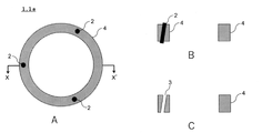
- FIG. 1A is a schematic top view of the surgical aid 1a
- FIG. 1B is a sectional view taken along the line XX'of FIG. 1A
- FIG. 1C is a view of FIG. 1B excluding the imaging unit 2.
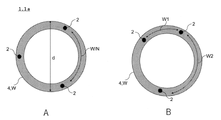
- 2A is a schematic top view of the surgical aid 1a
- FIG. 2B is a front view of FIG. 2A
- 3A and 3B are enlarged views of the circled portion of FIG. 2B.
- FIG. 4 is a view of FIG. 3A viewed from above, and is a diagram for explaining the direction d ⁇ in which the angle ⁇ is formed.
- 5A and 5B are diagrams for explaining the position where the image pickup unit 2 is arranged.
- 6A is a schematic top view of the surgical aid 1b
- FIG. 1B is a sectional view taken along the line XX'of FIG. 1A
- FIG. 1C is a view of FIG. 1B excluding the imaging unit 2.
- 2A is a schematic top view of the
- FIG. 6B is a sectional view taken along the line XX'of FIG. 6A
- FIG. 6C is an enlarged view of the portion circled in FIG. 6A, excluding the imaging unit 2.
- .. 7A is a schematic top view of the surgical aid 1c
- FIG. 7B is a sectional view taken along the line XX'of FIG. 7A
- FIG. 7C is a view of FIG. 7B excluding the imaging unit 2.
- 8A is a schematic top view of the surgical aid 1d
- FIG. 8B is a sectional view taken along the line XX'of FIG. 8A
- FIG. 8C is a view after rotating the holding portion 3a of FIG. 8B in the R1 direction.
- FIG. 8A is a schematic top view of the surgical aid 1c
- FIG. 8B is a sectional view taken along the line XX'of FIG. 8A
- FIG. 8C is a view after rotating the holding portion 3a of FIG. 8B in the R1
- FIG. 9 is a schematic top view of the surgical aid 1e.
- FIG. 10 is a schematic diagram showing an outline of the surgery support system 10.
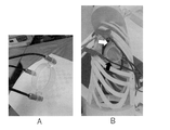
- FIG. 11A is a drawing substitute photograph, which is a photograph of the surgical aid produced in Example 1.
- FIG. 11B is a drawing substitute photograph, which is a photograph when a surgical aid is inserted into a simulated human body.
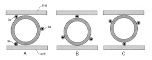
- 12A to 12C are diagrams showing the arrangement of surgical aids in an observation experiment in a body cavity using a simulated human body.
- 13A to 13C are drawings substitute photographs, which are composite images obtained in Example 3.
- 14A to 14C are drawings substitute photographs, which are composite images obtained in Example 4.
- 15A to 15C are drawings substitute photographs, which are composite images obtained in Example 5.
- 16A to 16C are drawings substitute photographs, which are composite images obtained in Example 6.
- FIG. 17 is a drawing substitute photograph, which is a composite image obtained in Example 7.
- FIG. 18D1 is a diagram showing the arrangement of the surgical aid produced in Comparative Example 1 on the simulated human body.
- FIG. 18D2 is a drawing substitute photograph, which is a composite image obtained in Comparative Example 1.
- FIG. 18A is a drawing substitute photograph and is the same as FIG. 14A.
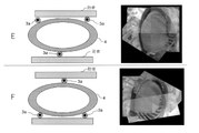
- 19E and 19F show the placement of the surgical aids made in Example 8 on a simulated human body and the synthetic images obtained.
- FIG. 1A is a schematic top view of the surgical aid 1a
- FIG. 1B is a sectional view taken along the line XX'of FIG. 1A
- FIG. 1C is a view of FIG. 1B excluding the imaging unit 2.
- the surgical aid 1a includes an imaging unit 2, a holding unit 3 for holding the imaging unit 2, and a base material 4.
- the base material 4 includes the holding portion 3.
- the imaging unit 2 is not particularly limited as long as it can image the inside of the body cavity.
- a CCD image sensor, a CMOS image sensor, a Foveon X3, an organic thin film image pickup element, and the like can be mentioned.
- the imaging range of the imaging unit 2 is not particularly limited. It is conceivable to use a wide-angle camera to image the inside of the body cavity with a single image pickup unit 2, but in that case, the edge of the image may be blurred. In addition, there is a possibility that some parts (shadow parts) cannot be imaged due to surgical instruments, organs, and the like.
- the surgical aid 1a since the surgical aid 1a includes three or more image pickup units 2, a field of view can be secured even by using the above-mentioned sensor or the like which is generally commercially available, and a shadowed portion can be reduced.
- the number (N) of the imaging unit 2 is not particularly limited as long as it is an integer of 3 or more, and examples thereof include 4 or more, 5 or more, and 6 or more.
- the upper limit of the image pickup unit 2 is not particularly limited, but if the number of image pickup units 2 is increased, the processing at the time of image composition becomes complicated and the cost increases.
- the upper limit of the number (N) of the image pickup unit 2 may be examined in consideration of cost, convenience of image processing (processing speed), and the like, for example, 20 or less, 15 or less, 10 or less, 8 or less, and the like. Can be mentioned.
- the holding unit 3 is provided on the base material 4 to hold the imaging unit 2.
- the holding portion 3 is formed so as to penetrate the base material 4, but as will be described later, the holder 3 holds the imaging unit 2 so as to have a predetermined angle. If possible, there are no particular restrictions on the shape or location.
- FIGS. 2 to 5 The angle of the image pickup unit 2 held by the holding unit 3 will be described with reference to FIGS. 2 to 5.
- 2A is a schematic top view of the surgical aid 1a (the description of the imaging unit 2 on the upper left is omitted for the sake of explanation)
- FIG. 2B is a front view of FIG. 2A (viewed from the arrow direction of FIG. 2A).
- .. 3A and 3B are enlarged views of the circled portion of FIG. 2B.
- FIG. 4 is a view of FIG. 3A viewed from above, and is a diagram for explaining the direction d ⁇ in which the angle ⁇ is formed.
- 5A and 5B are diagrams for explaining the position where the image pickup unit 2 is arranged.
- each image pickup unit 2 is arranged so as to face the outside of the base material 4 at an angle ⁇ of 0 degree or more and 10 degrees or less with respect to the reference line BL passing through each holding unit 3.
- the angle with the imaging unit 2 held by the holding portion 3 can be defined if the above-mentioned reference line condition is satisfied.
- the lower end side of the base material 4 is a virtual plane VF, but the virtual plane VF may be the upper end side of the base material 4.
- the surface including the upper end portion 31 of the holding portion 3 may be a virtual plane, or the surface including the lower end portion 32 of the holding portion 3 may be a virtual plane.
- the plane (least squares plane) obtained from the shape of the lower end side (or upper end side) of the base material 4 by the least squares method may be defined as the virtual plane VF.
- the least squares plane may be a virtual plane VF.
- the image pickup unit 2 is held by the holding unit 3 at an angle ⁇ of 0 degree or more and 10 degrees or less with respect to the reference line BL passing through the holding unit 3.
- the angle ⁇ is defined by the center line CL passing through the center of the imaging unit 2 and the reference line BL.
- the center of the imaging range (IR) of the imaging unit 2 may be the center line CL.
- the surgical aid 1a is used so as to be fitted into the incised portion with a scalpel during surgery.
- the surgical aid 1a is fitted in the direction of the arrow of the reference line BL. Therefore, the reference line BL can be said to be the insertion direction of the surgical aid 1a.
- the angle ⁇ between the image pickup unit 2 and the reference line BL is arranged so as to face the outside of the base material 4 at an angle ⁇ of 0 degree or more and 10 degrees or less.
- the angle ⁇ is preferably larger than 0 degrees, for example, 0.5 degrees or more, 1 degree or more, 1.5 degrees or more, 2 degrees or more, 2.5 degrees or more, 3 degrees or more, 3.5.
- the angle ⁇ of the image pickup unit 2 is 12 degrees or less, 11.5 degrees or less, 11 degrees or less, 10.5 degrees or less, 10 degrees or less, 9.5 degrees or less, 9 degrees or less, 8.5 degrees or less, 8 degrees or less, etc. It may be adjusted as appropriate.
- the angles ⁇ of the N image pickup units 2 may be the same or different.
- FIG. 4 is a diagram for explaining the direction d ⁇ in which the angle ⁇ is formed.
- the image pickup unit 2 is not particularly limited as long as the direction connecting the reference line BL to the center line CL of the image pickup unit 2 is arranged on the outside of the base material 4 (the direction away from the base material 4).
- the direction d ⁇ at which the angle ⁇ is formed is, for example, the reference line BL (or the image pickup unit 2 or the holding unit 3) from the substantially cylindrical virtual center VC. ) Can be mentioned.
- the virtual center VC may be the intersection of the long axis and the short axis.
- the virtual center VC may be, for example, the center of gravity.
- FIG. 4 is an example of the direction d ⁇ in which the angle ⁇ is formed, and may deviate from d ⁇ shown in FIG. 4 by a predetermined angle as long as it does not affect the image pickup by the image pickup unit 2. For example, when the deviation from d ⁇ shown in FIG.
- angles ⁇ of the N image pickup units 2 may be the same or different.
- the positions where N image pickup units 2 are arranged will be described.
- the image pickup units 2 may not be arranged at equal intervals on the base material 4 as long as the field of view can be secured.
- the outer peripheral length of the base material 4 is W
- N image pickup units 2 are arranged at equal intervals an arbitrary image pickup unit 2 and an adjacent image pickup unit 2 are used. The length is W / N.
- W1 when the imaging unit 2 is arranged at an arbitrary position, the shortest length of the adjacent imaging unit 2 is defined as W1 and the longest length is defined as W2.
- W / N 1, W1 may be 0.7 or more, 0.75 or more, 0.8 or more, 0.85 or more, and 0.9 or more.
- W2 may be 1.3 or less, 1.25 or less, 1.2 or less, 1.15 or less, and 1.1 or less. The same applies when the base material 4 is elliptical.
- the base material 4 is not particularly limited in material or the like as long as it can form the holding portion 3 and hold the imaging portion 2.
- a non-flexible member in which the shape of the base material 4 does not change can be mentioned.
- the substrate 4 may be formed of a flexible member whose shape changes when the surgical aid 1a is inserted into the incised portion.
- known medical materials can be used.
- the inflexible member include medical plastics such as polysulfone, polyvinylidene fluoride, polycarbonate and polypropylene; metals such as titanium and stainless steel.
- the flexible material include medical plastics such as silicon and polyvinyl chloride.
- the surgical aid 1a When the surgical aid 1a is used for video-assisted thoracoscopic surgery, the surgical aid 1a is placed between the ribs. Therefore, as shown in FIG. 5A, when the top view of the surgical aid 1a is substantially circular, the diameter d of the base material 4 is about 30 mm to 150 mm, preferably about 40 mm to 100 mm. When the surgical aid 1a is used for laparoscopic surgery, the diameter of the base material 4 is about 30 mm to 150 mm, preferably about 40 mm to 100 mm, but it may be larger than the above value because there are no ribs. When the base material 4 is not circular, the shortest distance may be set as the diameter among the distances obtained when the base material 4 is sandwiched between parallel lines such as calipers.
- the distance between the image pickup unit and the image pickup unit may be too large. Therefore, when the shortest distance is 1 among the distances obtained when the base material 4 is sandwiched between parallel lines such as calipers, the longest distance is 2 or less, 1.9 or less, and 1.8 or less. It may be 1.7 or less, 1.6 or less, 1.5 or less, and the like.
- the surgical aid 1a according to the embodiment can be manufactured by forming a base material 4 having a holding portion 3 using a 3D printer or the like and inserting the imaging unit 2 into the holding portion 3.
- the surgical support system When the surgical support system is constructed using the surgical assist tool 1a according to the embodiment, an image that gives a bird's-eye view of the inside of the body cavity can be obtained from the place where the surgical assist tool 1a is arranged. Therefore, it is possible to secure the necessary field of view during surgery. Further, when operating a surgical instrument or the like, even if a portion that cannot be imaged by the surgical instrument occurs in one imaging unit, the inside of the body cavity can be imaged by another imaging unit. Further, since the relative positional relationship of the image pickup unit 2 does not change, images can be easily combined without using a position sensor or the like.
- FIG. 6 shows a modification 1 of the holding portion 3.
- 6A is a schematic top view of the surgical aid 1b
- FIG. 6B is a sectional view taken along the line XX'of FIG. 6A
- FIG. 6C is an enlarged view of the portion circled in FIG. 6A, excluding the imaging unit 2. ..
- the holding portion 3 of the surgical aid 1a shown in FIGS. 6A to 6C has a notch formed on the outer peripheral surface of the base material 4.
- the image pickup unit 2 can be fitted from the outer peripheral surface of the base material 4. Therefore, in addition to the effect of the surgical aid 1a, the effect of facilitating the attachment of the imaging unit 2 is obtained.
- FIG. 7 shows a modification 2 of the holding portion 3.
- 7A is a schematic top view of the surgical aid 1c
- FIG. 7B is a sectional view taken along the line XX'of FIG. 7A
- FIG. 7C is a view of FIG. 7B excluding the imaging unit 2.
- the holding portion 3a of the surgical aid 1c shown in FIGS. 7A to 7C is formed as a separate body from the base material 4.
- the holding portion 3 of the surgical aid 1a is a through hole penetrating the base material 4.
- the holding portion 3a according to the modified example 2 is different from the holding portion 3 of the surgical assist tool 1a in that a through hole 3c for holding the imaging portion 2 is formed in the holding portion base material 3b.
- the same material as the base material 4 can be used for the holding portion base material 3b, but the material forming the base material 4 and the material forming the holding portion base material 3b may be the same or different. good.
- the angle of the imaging unit 2 held in the through hole 3c is the same as that of the surgical aid 1a.
- the through hole 3c is formed so as to penetrate the holding portion base material 3b, but as shown in the modified example 1, a notch is formed on the outer peripheral surface of the holding portion base material 3b. Then, the image pickup unit 2 may be fitted from the outer peripheral surface of the holding portion base material 3b. Further, in the examples shown in FIGS.
- the holding portion 3a and the base material 4 are directly connected to each other.
- the holding portion 3a and the base material 4 may be connected via a connecting portion (not shown).
- the holding portion 3a is formed as a separate body from the base material 4, but the holding portion 3a is directly or indirectly connected to the base material 4. Therefore, it may be said that the holding portion 3a shown in FIGS. 7A to 7C is indirectly included in the base material 4.
- the holding portion 3a protrudes to the outside of the base material 4.
- the diameter of the base material 4 when used for video-assisted thoracoscopic surgery is about 30 mm to 150 mm, preferably about 40 mm to 100 mm.
- the diameter of the base material 4 when used for laparoscopic surgery is about 30 mm to 150 mm, preferably about 40 mm to 100 mm, but it may be larger than the above value because there are no ribs.
- the diameter of the circumscribed circle of the holding portion 3a may be replaced with the diameter of the base material 4 of the surgical aid 1a.
- the shortest distance may be set as the diameter among the distances obtained when the circumscribed circle is sandwiched between parallel lines.
- the longest distance is 2 or less, 1.9 or less, 1.8 or less, 1.7 or less, 1.6 or less, 1.5 or less, etc. You may do it.
- the surgical aid 1c provided with the holding portion 3a of the modified example 2 has the effect of reducing the pain of the patient because the opening and closing of the ribs can be reduced in addition to the effect of the surgical aid 1a.
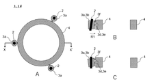
- FIG. 8 shows a modification 3 of the holding portion 3.
- 8A is a schematic top view of the surgical aid 1d
- FIG. 8B is a sectional view taken along the line XX'of FIG. 8A
- FIG. 8C is a view after rotating the holding portion 3a of FIG. 8B in the R1 direction.
- the holding portion 3a of the surgical aid 1d shown in FIGS. 8A to 8C is rotatably formed with respect to the base material 4. In other words, it differs from the modified example 2 of the holding portion 3 in that the angle of the imaging unit 2 with respect to the reference line is formed to be variable.
- a substantially spherical convex portion 3d is formed on the side surface of the holding portion base material 3b.
- a substantially spherical recess 3e is formed in the base material 4.
- the stopper 3f is arranged above the holding portion base material 3b so as to come into contact with the base material 4.
- the stopper 3f is provided below the holding unit base material 3b so that it can rotate in the direction opposite to R1. Just do it.
- FIGS. 8A to 8C are merely examples in which the holding portion 3a is rotatably formed with respect to the base material 4, and may be other examples.
- a substantially spherical convex portion may be formed on the base material 4
- a substantially spherical concave portion may be formed on the holding portion base material 3b.
- the ratchet mechanism may be used so that the holding portion 3a can rotate stepwise with respect to the base material 4.
- all the holding portions 3a are formed so as to be rotatable with respect to the base material 4, but a part of the holding portions 3a is formed with respect to the base material 4.
- a notch is formed on the outer peripheral surface of the holding portion base material 3b, and the imaging unit 2 is fitted from the outer peripheral surface of the holding portion base material 3b. But it may be.
- the surgical aid 1d provided with the holding portion 3a of the modified example 3 has an effect that the angle of the imaging portion 2 with respect to the reference line can be changed according to the size and usage of the patient, in addition to the effect of the surgical assist tool 1a. Play.
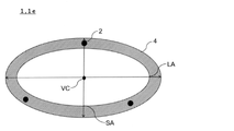
- FIG. 9 shows a modification 1 of the base material 4.
- FIG. 9 is a schematic top view of the surgical aid 1e.
- the base material 4 may be either a flexible material or a non-flexible material.
- the modification 1 shown in FIG. 9 differs from the surgical aid 1a according to the embodiment in that the base material 4 is formed of a non-flexible member and is formed in a substantially elliptical shape.
- the ratio of the elliptical long axis LA to the short axis SA is not particularly limited as long as a sufficient field of view can be secured.
- LA / SA is 2 or less, 1.9 or less, 1.8 or less, 1.7 or less, 1.6 or less, 1.5 or less, and the like.
- the short axis SA corresponds to the diameter of the surgical aid 1a.
- the relationship between the imaging unit 2 and the holder 3 when the base material 4 is formed into an elliptical shape is the surgical support tool according to the embodiment, except that the virtual center VC is an intersection with the long axis LA and the short axis SA. This is the same as 1a and its modifications 1b to 1d.
- the surgical aid 1 When using the surgical aid 1 for video-assisted thoracoscopic surgery, it is necessary to place it between the ribs. Therefore, although the distance between the ribs can be expanded by using an instrument, the size of the surgical aid 1 depends on the distance between the ribs.
- the base material of the surgical aid 1 is substantially circular, it is necessary to arrange the imaging unit on the circular base material within the above size.
- the short axis SA depends on the distance between the ribs, but the long axis LA does not depend on the distance between the ribs. Therefore, the surgical aid 1e provided with the substantially elliptical base material 4 shown in FIG. 9 has the effect of improving the degree of freedom in the mounting position of the imaging unit 2 in addition to the effect of the surgical aid 1a. In addition, since the ribs can be opened and closed less, the patient's pain can be reduced.
- the surgical aids 1a to 1e shown in FIGS. 1 to 9 are new instruments different from the instruments conventionally used for surgery.
- a surgical aid may be produced by forming a holding portion 3 on an instrument already used for surgery and attaching the imaging portion 2.
- Alexis® Wound Drtractor with the purpose of reducing the risk of wound infection, providing a good field of view, and providing the largest incision with the smallest incision size. (Wound Protector) is known.
- Wound tractors are known to have various sizes, from an XXS (extra extra small) size with an incision length of 10 mm to 30 mm to an XXL (extra extra large) size with an incision length of 170 mm to 250 mm.
- the wound tractor is formed of an outer ring, an inner ring, and a film called a wound sheath that connects both rings.
- a surgical aid can be manufactured by forming the holding portion 3 on the inner ring to be inserted into the incision portion and attaching the imaging portion 2.
- FIG. 10 is a schematic diagram showing an outline of the surgery support system 10.
- the surgical support system 10 includes at least a surgical assist tool 1 and an image processing unit 11 that synthesizes an image obtained from the imaging unit 2. Further, optionally, a display unit 12 for displaying an image processed by the image processing unit 11 may be included.
- any of the surgical aids shown in FIGS. 1 to 9 and modified examples thereof (1a to 1e) may be used.
- the image processing unit 11 is not particularly limited as long as it can synthesize the images obtained from the N image pickup units 2, and may synthesize the images by a known image synthesis method. Alternatively, an image composition algorithm may be created based on a known image composition technique.
- the display unit 12 is not particularly limited as long as it can display the image processed by the image processing unit 11, and a known monitor such as a liquid crystal monitor or an organic EL monitor may be used.
- the image processing unit 11 stores a program capable of synthesizing the images obtained from the N image pickup units 2.
- the program is not particularly limited as long as the images obtained from the N image pickup units 2 can be combined, and can be used as a program of the surgery support system.
- the program may perform image processing utilizing the features of the surgical aid 1 disclosed in this application.
- the surgical aid 1 disclosed in the present application includes N image pickup units 2, even if a part of the body cavity cannot be imaged by the surgical instrument in one image pickup unit 2, another image pickup unit 2 is provided. It may be possible to image the inside of the body cavity.
- the program may perform image processing so that when an arbitrary imaging unit 2 captures an image of a surgical instrument, an image captured by another imaging unit 2 can be displayed.
- the imaging of the surgical instrument detection of the surgical instrument
- the surgical instrument may be imaged in the area that is imaged by a single imaging unit 2.
- the program may perform image processing using the image in the body cavity captured before detecting the imaging of the surgical instrument. For example, before the start of surgery, an image of the inside of the body cavity may be imaged and stored, or an image of the past several seconds may be stored, and image processing may be performed based on the stored image so that the surgical instrument cannot be seen.
- the program performs image processing so that a VR-like image can be displayed, such as displaying the image captured by the imaging unit 2 as it is and displaying information necessary for surgery together. You may go. Providing these programs separately will improve the convenience of the surgery support system.
- any combination of the above-described embodiments can be freely combined, any component of each embodiment can be modified, or any component can be omitted.
- any component may be added to each of the above embodiments. For example, by changing the frequency of the light source that irradiates the inside of the body cavity, a function may be added so that the depth inside the body cavity can be known.
- Example 1 Agillista-3100 (manufactured by KEYENCE CORPORATION) was used as a material for forming the holding portion 3a and the base material 4, and the holding portion 3a and the base material 4 were integrally molded using a 3D printer.
- the holding portions 3a were formed so that the three holding portions 3a were evenly spaced.
- the base material 4 had a substantially cylindrical shape, and the diameter of the base material 4 was about 60 mm.
- the length from the outer periphery of the base material 4 to the end of the holding portion 3a was about 17 mm.
- FIG. 11A is a photograph of the surgical aid produced in Example 1.
- the angles of the three image pickup units 2 with respect to the reference line were all designed to be the same. Further, in order to carry out various examples described later, a surgical aid was produced in which the angle of the imaging unit 2 with respect to the reference line was 0 °, 3 °, 5 °, and 10 °.
- the angle of the image pickup unit 2 with respect to the reference line was designed to face outward from the center of the base material 4.
- Example 2 The imaging unit of the surgical aid produced in Example 1 and the image processing unit that synthesizes images by an algorithm developed by the inventor (extended function based on OpenCV (Open Source Computer Vision Library)) were connected. Next, a surgical support system was created by connecting the image processing unit and the monitor.
- OpenCV Open Source Computer Vision Library
- FIG. 11B is a photograph when a surgical aid is inserted into a simulated human body.
- the black arrow portion in FIG. 11B is a surgical aid inserted.
- the simulated human body shown in FIG. 11B is Fasotec THORA (manufactured by Fasotech Co., Ltd.), and the white arrow portion is a simulated lung.
- FIG. 12 is a diagram showing the arrangement of surgical aids in an observation experiment in a body cavity using a simulated human body.
- the surgical aid was placed so that the line connecting the two holding portions 3a was substantially vertical to the upper and lower ribs, and the other holding portion 3a was located in the middle of the ribs.
- the surgical aid was placed by rotating 30 degrees clockwise from the arrangement shown in FIG. 12A.
- the surgical aid was placed by rotating 30 degrees counterclockwise from the arrangement shown in FIG. 12A.
- the images A, B, and C in each of the figures shown in the following examples are images taken at the positions A, B, and C in FIG. 12, respectively.
- Examples 3 to 7 The angle of the image pickup unit 2 with respect to the reference line is An image of 0 degrees (Example 3) is shown in FIG. ⁇ The image of one degree (Example 4) is shown in FIG. ⁇ The image of 3 degrees (Example 5) is shown in FIG. An image of 5 degrees (Example 6) is shown in FIG. An image of 10 degrees (Example 7) is shown in FIG. Shown in.
- the synthetic image shown in FIG. 13A showed a partial defect in the upper part of the simulated lung
- the synthetic images shown in FIGS. 13B and 13C were able to secure the visual field in the thoracic cavity including the simulated lung. Therefore, it was confirmed that even when the surgical aid with an angle of 0 degree prepared in Example 1 was used, the necessary visual field for the arthroscopic surgery could be secured by adjusting the arrangement of the ribs and the imaging portion.
- the viewing area of the image pickup unit 2 was larger than that of Example 3 at an angle of 0 degrees.
- the partial defect in the upper part of the simulated lung seen in the synthetic image of FIG. 13A was not found in FIG. 14A, and the entire simulated lung could be confirmed.
- the central part of the simulated lung was slightly difficult to see. Therefore, the images captured by each imaging unit before image composition were confirmed.
- the three images in the upper part of FIG. 17A are images taken by each image pickup unit before image composition. From the upper three images, it was found that each imaging unit captured more of the outer portion than the simulated lung, and there were few overlapping images of the central portion of the simulated lung. From the viewpoint of ensuring a sufficient field of view during surgery, there is no problem even if the angle shown in FIG. 17 is 10 degrees, but when the viewpoint of observing the tissue in the thoracic cavity is added, the angle is about 10 degrees. It became clear that it was desirable to do so.
- FIG. 18D1 shows the surgical aids produced in Comparative Example 1 and their placement on a simulated human body.
- the number of holding portions 3a holding the imaging unit was set to 2
- the line connecting the two holding portions 3a was arranged so as to pass substantially the center of the base material 4.
- the angle of the imaging unit with respect to the reference line was 1 degree, and the two holding units 3a were arranged so as to be in contact with the ribs.
- FIG. 18D2 is a composite image obtained in Comparative Example 1. Further, as a control, a composite image (FIG.
- Example 8> 19E and 19F show the surgical aids and placements on the simulated human body produced in Example 8.
- the surgical aid prepared in Example 8 is -
- the base material 4 has an elliptical shape with a major axis of 6 cm and a minor axis of 3 cm.
- One of the holding portions 3a is arranged at the intersection of the minor axis of the ellipse and the base material, and the other two are arranged at equal intervals so that the angle with the center of the ellipse is 120 degrees.
- the angle of each image pickup unit was 5 degrees, and it was arranged so as to face outward from the center of the ellipse. Except for this, a surgical aid was prepared in the same procedure as in Example 1, and then a surgical support system was prepared in the same procedure as in Example 2.
- FIGS. 19E and 19F The right side of FIGS. 19E and 19F is a composite image according to the arrangement of the surgical aid on the left side. As shown in FIGS. 19E and 19F, it was confirmed that even when the base material 4 has an elliptical shape, imaging can be performed without any problem.
- the surgical aids and surgical support systems disclosed in this application can secure a wide field of view during arthroscopic surgery. Therefore, it is useful for the medical device manufacturing industry.
Landscapes
- Health & Medical Sciences (AREA)
- Life Sciences & Earth Sciences (AREA)
- Surgery (AREA)
- Engineering & Computer Science (AREA)
- Nuclear Medicine, Radiotherapy & Molecular Imaging (AREA)
- General Health & Medical Sciences (AREA)
- Biomedical Technology (AREA)
- Heart & Thoracic Surgery (AREA)
- Medical Informatics (AREA)
- Molecular Biology (AREA)
- Animal Behavior & Ethology (AREA)
- Public Health (AREA)
- Veterinary Medicine (AREA)
- Pathology (AREA)
- Radiology & Medical Imaging (AREA)
- Biophysics (AREA)
- Optics & Photonics (AREA)
- Physics & Mathematics (AREA)
- Signal Processing (AREA)
- Multimedia (AREA)
- Orthopedic Medicine & Surgery (AREA)
- Physical Education & Sports Medicine (AREA)
- Oral & Maxillofacial Surgery (AREA)
- Gynecology & Obstetrics (AREA)
- Surgical Instruments (AREA)
- Endoscopes (AREA)
Priority Applications (4)
| Application Number | Priority Date | Filing Date | Title |
|---|---|---|---|
| CN202180063689.0A CN116194057A (zh) | 2020-10-29 | 2021-10-25 | 手术辅助工具和手术支持系统 |
| JP2022559123A JPWO2022092026A1 (https=) | 2020-10-29 | 2021-10-25 | |
| EP21886144.1A EP4238524A4 (en) | 2020-10-29 | 2021-10-25 | Surgery assistance tool and surgery assistance system |
| US18/245,713 US20240016515A1 (en) | 2020-10-29 | 2021-10-25 | Surgical assistance device and surgery support system |
Applications Claiming Priority (2)
| Application Number | Priority Date | Filing Date | Title |
|---|---|---|---|
| JP2020181155 | 2020-10-29 | ||
| JP2020-181155 | 2020-10-29 |
Publications (1)
| Publication Number | Publication Date |
|---|---|
| WO2022092026A1 true WO2022092026A1 (ja) | 2022-05-05 |
Family
ID=81382438
Family Applications (1)
| Application Number | Title | Priority Date | Filing Date |
|---|---|---|---|
| PCT/JP2021/039295 Ceased WO2022092026A1 (ja) | 2020-10-29 | 2021-10-25 | 手術補助具および手術支援システム |
Country Status (5)
| Country | Link |
|---|---|
| US (1) | US20240016515A1 (https=) |
| EP (1) | EP4238524A4 (https=) |
| JP (1) | JPWO2022092026A1 (https=) |
| CN (1) | CN116194057A (https=) |
| WO (1) | WO2022092026A1 (https=) |
Families Citing this family (1)
| Publication number | Priority date | Publication date | Assignee | Title |
|---|---|---|---|---|
| WO2022090870A1 (en) * | 2020-10-28 | 2022-05-05 | Alcon Inc. | Imaging tool to support eye surgery |
Citations (9)
| Publication number | Priority date | Publication date | Assignee | Title |
|---|---|---|---|---|
| US20090259102A1 (en) * | 2006-07-10 | 2009-10-15 | Philippe Koninckx | Endoscopic vision system |
| WO2009144729A1 (en) * | 2008-05-28 | 2009-12-03 | Technion Research & Development Foundation Ltd. | Laparoscopic camera array |
| US8027710B1 (en) * | 2005-01-28 | 2011-09-27 | Patrick Dannan | Imaging system for endoscopic surgery |
| US20130282041A1 (en) * | 2012-04-20 | 2013-10-24 | Erhan H. Gunday | Viewing Trocar |
| JP5975504B2 (ja) | 2014-07-24 | 2016-08-23 | アドバンストヘルスケア株式会社 | トロカール,ポート,手術支援システム |
| WO2017163407A1 (ja) * | 2016-03-25 | 2017-09-28 | 株式会社ニコン | 内視鏡装置、内視鏡システム、及びそれらを備えた手術システム |
| JP2017536215A (ja) * | 2014-09-15 | 2017-12-07 | ヴィヴィッド メディカル インコーポレイテッド | 単回使用の、ポートを利用して展開可能かつ関節操作可能な内視鏡 |
| JP2018042625A (ja) * | 2016-09-12 | 2018-03-22 | 株式会社デルコ | 撮像機能付きトロッカー |
| JP2018524085A (ja) * | 2015-06-26 | 2018-08-30 | アパマ・メディカル・インコーポレーテッド | 組織マッピングおよび可視化システム |
Family Cites Families (9)
| Publication number | Priority date | Publication date | Assignee | Title |
|---|---|---|---|---|
| US9872609B2 (en) * | 2009-06-18 | 2018-01-23 | Endochoice Innovation Center Ltd. | Multi-camera endoscope |
| JP5424388B2 (ja) * | 2009-08-31 | 2014-02-26 | 国立大学法人鳥取大学 | 撮像装置 |
| US20130250081A1 (en) * | 2012-03-21 | 2013-09-26 | Covidien Lp | System and method for determining camera angles by using virtual planes derived from actual images |
| US9629523B2 (en) * | 2012-06-27 | 2017-04-25 | Camplex, Inc. | Binocular viewing assembly for a surgical visualization system |
| US9642606B2 (en) * | 2012-06-27 | 2017-05-09 | Camplex, Inc. | Surgical visualization system |
| US10349824B2 (en) * | 2013-04-08 | 2019-07-16 | Apama Medical, Inc. | Tissue mapping and visualization systems |
| JP6834258B2 (ja) * | 2016-08-31 | 2021-02-24 | セイコーエプソン株式会社 | 表示装置、表示システム及び表示装置の制御方法 |
| US20190290371A1 (en) * | 2016-09-29 | 2019-09-26 | Medrobotics Corporation | Optical systems for surgical probes, systems and methods incorporating the same, and methods for performing surgical procedures |
| CN111356411B (zh) * | 2017-06-21 | 2023-12-05 | 阿帕玛医疗公司 | 用于消融系统的图形用户界面 |
-
2021
- 2021-10-25 EP EP21886144.1A patent/EP4238524A4/en active Pending
- 2021-10-25 WO PCT/JP2021/039295 patent/WO2022092026A1/ja not_active Ceased
- 2021-10-25 CN CN202180063689.0A patent/CN116194057A/zh active Pending
- 2021-10-25 US US18/245,713 patent/US20240016515A1/en active Pending
- 2021-10-25 JP JP2022559123A patent/JPWO2022092026A1/ja active Pending
Patent Citations (9)
| Publication number | Priority date | Publication date | Assignee | Title |
|---|---|---|---|---|
| US8027710B1 (en) * | 2005-01-28 | 2011-09-27 | Patrick Dannan | Imaging system for endoscopic surgery |
| US20090259102A1 (en) * | 2006-07-10 | 2009-10-15 | Philippe Koninckx | Endoscopic vision system |
| WO2009144729A1 (en) * | 2008-05-28 | 2009-12-03 | Technion Research & Development Foundation Ltd. | Laparoscopic camera array |
| US20130282041A1 (en) * | 2012-04-20 | 2013-10-24 | Erhan H. Gunday | Viewing Trocar |
| JP5975504B2 (ja) | 2014-07-24 | 2016-08-23 | アドバンストヘルスケア株式会社 | トロカール,ポート,手術支援システム |
| JP2017536215A (ja) * | 2014-09-15 | 2017-12-07 | ヴィヴィッド メディカル インコーポレイテッド | 単回使用の、ポートを利用して展開可能かつ関節操作可能な内視鏡 |
| JP2018524085A (ja) * | 2015-06-26 | 2018-08-30 | アパマ・メディカル・インコーポレーテッド | 組織マッピングおよび可視化システム |
| WO2017163407A1 (ja) * | 2016-03-25 | 2017-09-28 | 株式会社ニコン | 内視鏡装置、内視鏡システム、及びそれらを備えた手術システム |
| JP2018042625A (ja) * | 2016-09-12 | 2018-03-22 | 株式会社デルコ | 撮像機能付きトロッカー |
Non-Patent Citations (1)
| Title |
|---|
| See also references of EP4238524A4 |
Also Published As
| Publication number | Publication date |
|---|---|
| EP4238524A4 (en) | 2024-04-10 |
| EP4238524A1 (en) | 2023-09-06 |
| US20240016515A1 (en) | 2024-01-18 |
| CN116194057A (zh) | 2023-05-30 |
| JPWO2022092026A1 (https=) | 2022-05-05 |
Similar Documents
| Publication | Publication Date | Title |
|---|---|---|
| JP6585804B2 (ja) | 光学トロカール可視化システムおよび装置 | |
| CN113453606B (zh) | 具有双图像传感器的内窥镜 | |
| AU2017202106B2 (en) | Thoracic endoscope for surface scanning | |
| JP6389467B2 (ja) | 低侵襲手術のための分離されたマルチカメラシステム | |
| US12318064B2 (en) | Thoracic imaging, distance measuring, surgical awareness, and notification system and method | |
| US9895143B2 (en) | Medical system and method of controlling medical instruments | |
| EP3078317A1 (en) | Method for controlling endoscope and endoscope system | |
| Pillai et al. | Endoscopic image-guided transoral approach to the craniovertebral junction: an anatomic study comparing surgical exposure and surgical freedom obtained with the endoscope and the operating microscope | |
| US20070270651A1 (en) | Device and method for illuminating an in vivo site | |
| US12396633B2 (en) | Multi-camera imaging system | |
| US20160360120A1 (en) | Endoscope system and method of controlling endoscope system | |
| US20130225926A1 (en) | Systems and methods for directing instruments to varying positions at the distal end of a guide tube | |
| JP2010253270A (ja) | 視覚型ベレス針アセンブリ | |
| TW201124106A (en) | Collision avoidance and detection using distance sensors | |
| KR20140090927A (ko) | 투관침 및 수술지원시스템 | |
| EP2522270B1 (en) | Pivoted three-dimensional video endoscope | |
| JP6018295B2 (ja) | 医療器具案内装置 | |
| US9999443B2 (en) | Instrument head single loader | |
| WO2022092026A1 (ja) | 手術補助具および手術支援システム | |
| US12127734B2 (en) | Apparatus and method for 3D surgical imaging | |
| JP2007307090A (ja) | 内視鏡、内視鏡アタッチメント、および、内視鏡装置 | |
| JP2019130005A (ja) | 撮像装置、表示システムおよび手術システム | |
| JP2009125392A (ja) | 内視鏡システムおよび内視鏡装置 | |
| WO2023203908A1 (ja) | 手術支援システムおよび手術支援装置 | |
| JP2001204739A (ja) | 顕微鏡下手術支援システム |
Legal Events
| Date | Code | Title | Description |
|---|---|---|---|
| 121 | Ep: the epo has been informed by wipo that ep was designated in this application |
Ref document number: 21886144 Country of ref document: EP Kind code of ref document: A1 |
|
| ENP | Entry into the national phase |
Ref document number: 2022559123 Country of ref document: JP Kind code of ref document: A |
|
| NENP | Non-entry into the national phase |
Ref country code: DE |
|
| ENP | Entry into the national phase |
Ref document number: 2021886144 Country of ref document: EP Effective date: 20230530 |