WO2022092016A1 - 印刷装置、および、印刷方法 - Google Patents
印刷装置、および、印刷方法 Download PDFInfo
- Publication number
- WO2022092016A1 WO2022092016A1 PCT/JP2021/039274 JP2021039274W WO2022092016A1 WO 2022092016 A1 WO2022092016 A1 WO 2022092016A1 JP 2021039274 W JP2021039274 W JP 2021039274W WO 2022092016 A1 WO2022092016 A1 WO 2022092016A1
- Authority
- WO
- WIPO (PCT)
- Prior art keywords
- bottle
- work
- printing
- blanket roll
- drive
- Prior art date
- Legal status (The legal status is an assumption and is not a legal conclusion. Google has not performed a legal analysis and makes no representation as to the accuracy of the status listed.)
- Ceased
Links
Images



Classifications
-
- B—PERFORMING OPERATIONS; TRANSPORTING
- B41—PRINTING; LINING MACHINES; TYPEWRITERS; STAMPS
- B41F—PRINTING MACHINES OR PRESSES
- B41F17/00—Printing apparatus or machines of special types or for particular purposes, not otherwise provided for
- B41F17/08—Printing apparatus or machines of special types or for particular purposes, not otherwise provided for for printing on filamentary or elongated articles, or on articles with cylindrical surfaces
- B41F17/14—Printing apparatus or machines of special types or for particular purposes, not otherwise provided for for printing on filamentary or elongated articles, or on articles with cylindrical surfaces on articles of finite length
- B41F17/20—Printing apparatus or machines of special types or for particular purposes, not otherwise provided for for printing on filamentary or elongated articles, or on articles with cylindrical surfaces on articles of finite length on articles of uniform cross-section, e.g. pencils, rulers, resistors
-
- B—PERFORMING OPERATIONS; TRANSPORTING
- B41—PRINTING; LINING MACHINES; TYPEWRITERS; STAMPS
- B41F—PRINTING MACHINES OR PRESSES
- B41F17/00—Printing apparatus or machines of special types or for particular purposes, not otherwise provided for
- B41F17/08—Printing apparatus or machines of special types or for particular purposes, not otherwise provided for for printing on filamentary or elongated articles, or on articles with cylindrical surfaces
- B41F17/14—Printing apparatus or machines of special types or for particular purposes, not otherwise provided for for printing on filamentary or elongated articles, or on articles with cylindrical surfaces on articles of finite length
- B41F17/20—Printing apparatus or machines of special types or for particular purposes, not otherwise provided for for printing on filamentary or elongated articles, or on articles with cylindrical surfaces on articles of finite length on articles of uniform cross-section, e.g. pencils, rulers, resistors
- B41F17/22—Printing apparatus or machines of special types or for particular purposes, not otherwise provided for for printing on filamentary or elongated articles, or on articles with cylindrical surfaces on articles of finite length on articles of uniform cross-section, e.g. pencils, rulers, resistors by rolling contact
-
- B—PERFORMING OPERATIONS; TRANSPORTING
- B41—PRINTING; LINING MACHINES; TYPEWRITERS; STAMPS
- B41F—PRINTING MACHINES OR PRESSES
- B41F3/00—Cylinder presses, i.e. presses essentially comprising at least one cylinder co-operating with at least one flat type-bed
- B41F3/18—Cylinder presses, i.e. presses essentially comprising at least one cylinder co-operating with at least one flat type-bed of special construction or for particular purposes
- B41F3/20—Cylinder presses, i.e. presses essentially comprising at least one cylinder co-operating with at least one flat type-bed of special construction or for particular purposes with fixed type-beds and travelling impression cylinders
-
- B—PERFORMING OPERATIONS; TRANSPORTING
- B41—PRINTING; LINING MACHINES; TYPEWRITERS; STAMPS
- B41F—PRINTING MACHINES OR PRESSES
- B41F33/00—Indicating, counting, warning, control or safety devices
- B41F33/04—Tripping devices or stop-motions
-
- B—PERFORMING OPERATIONS; TRANSPORTING
- B41—PRINTING; LINING MACHINES; TYPEWRITERS; STAMPS
- B41M—PRINTING, DUPLICATING, MARKING, OR COPYING PROCESSES; COLOUR PRINTING
- B41M1/00—Inking and printing with a printer's forme
- B41M1/10—Intaglio printing ; Gravure printing
-
- B—PERFORMING OPERATIONS; TRANSPORTING
- B41—PRINTING; LINING MACHINES; TYPEWRITERS; STAMPS
- B41M—PRINTING, DUPLICATING, MARKING, OR COPYING PROCESSES; COLOUR PRINTING
- B41M1/00—Inking and printing with a printer's forme
- B41M1/26—Printing on other surfaces than ordinary paper
- B41M1/34—Printing on other surfaces than ordinary paper on glass or ceramic surfaces
-
- B—PERFORMING OPERATIONS; TRANSPORTING
- B41—PRINTING; LINING MACHINES; TYPEWRITERS; STAMPS
- B41M—PRINTING, DUPLICATING, MARKING, OR COPYING PROCESSES; COLOUR PRINTING
- B41M1/00—Inking and printing with a printer's forme
- B41M1/40—Printing on bodies of particular shapes, e.g. golf balls, candles, wine corks
Definitions
- the technique disclosed in the specification of the present application relates to a printing technique.
- the work rotates according to its rotation while in contact with the blanket roll.
- the work may be pulled in the rotational direction due to contact with or friction with the blanket roll, resulting in misalignment of the work.
- the misalignment of the work causes a misalignment of the printing position, which may deteriorate the print quality.
- the technique disclosed in the specification of the present application was made in view of the problems described above, and is a technique for suppressing the misalignment of the work when printing on the work.
- the printing apparatus is in contact with a holder for holding a work which is a rotational symmetry body rotatably around an axis of rotational symmetry and the work rotating in the holder. While rotating with the work, a blanket roll for printing on the work, a first drive source for rotating the work held in the holder, and a blanket roll for rotating the blanket roll.
- a second drive source and a control device for controlling the drive of the first drive source and the drive of the second drive source are provided, and the control device is in contact with the work and the blanket roll.
- the drive of the first drive source and the drive of the second drive source are controlled so that the circumferential speed of the work in the portion is higher than the circumferential speed of the blanket roll in the contact portion.
- the printing apparatus relates to the printing apparatus according to the first aspect, and the control device is such that the circumferential speed of the work at the contact portion is the same.
- the drive of the first drive source and the drive of the second drive source are controlled so as to be 1% or more and 5% or less faster than the speed in the circumferential direction of the blanket roll at the contact portion.
- the printing apparatus according to the third aspect of the technique disclosed in the present specification relates to the printing apparatus according to the first or second aspect, and is located upstream of the contact portion in the rotational direction of the work. Further, a backup roller for contacting the work is further provided.
- the printing apparatus according to the fourth aspect of the technique disclosed in the present specification relates to the printing apparatus according to any one of the first to the third aspects, and is more than the contact portion in the rotational direction of the work. It is located on the downstream side and further includes a curing unit for curing the ink printed on the work.
- a printing method is a step of rotatably holding a work which is a rotational symmetry body around an axis of rotational symmetry, and a blanket roll is brought into contact with the rotating work.
- the work is provided with a step of printing on the work by rotating the work together with the work, and in the step of printing on the work, the speed in the circumferential direction of the work at the contact portion between the work and the blanket roll is the contact.
- the drive of the first drive source for rotating the work and the drive of the second drive source for rotating the blanket roll are controlled so as to be faster than the speed in the circumferential direction of the blanket roll in the unit. While doing so, it is a step of printing on the work.
- the printing method according to the sixth aspect of the technique disclosed in the present specification relates to the printing method according to the fifth aspect, and the step of printing on the work is in the circumferential direction of the work at the contact portion.
- the drive of the first drive source and the drive of the second drive source are performed so that the speed is 1% or more and 5% or less faster than the speed in the circumferential direction of the blanket roll at the contact portion. This is a process of printing on the work while controlling it.
- the rotating work is on the opposite side of the rotation direction because the circumferential speed of the work is faster than the circumferential speed of the blanket roll. Receives frictional resistance. Therefore, when printing on the work, it is possible to suppress the misalignment of the work.
- ordinal numbers such as “first” or “second” may be used in the description described below, these terms facilitate the understanding of the content of the embodiments. It is used for convenience, and is not limited to the order that can be generated by these ordinal numbers.
- FIGS. 1 and 2 are diagrams schematically showing an example of the configuration of the printing apparatus 100 according to the present embodiment.
- the bottle 8 is shown as an example of a work that is a rotationally symmetric body (including a cylindrical shape and a polygonal shape), and the side surface 80 of the bottle 8 is shown as an example of the side surface of the work.
- the bottle 8 transported by a transport unit (not shown) is detachably held in the holder 300.
- the form of the holder 300 is not limited to that shown in FIGS. 1 and 2, and may be any form that can hold the bottle 8.
- the printing device 100 includes at least one printing unit 101 and a control device 9.
- the printing unit 101 prints, for example, a single color on the side surface 80 of the bottle 8.
- multicolor printing including two-color printing is realized by performing single-color printing of different colors by each printing unit 101.
- the drive of the printing unit 101 in the printing device 100 is controlled by the control device 9.
- the control device 9 is, for example, a hard disk drive (Hard disk drive, that is, HDD), a random access memory (random access memory, that is, RAM), a read-only memory (read only memory, that is, ROM), and a flash memory.
- a storage device including a memory (storage medium) including a volatile or non-volatile semiconductor memory, a magnetic disk, a flexible disk, an optical disk, a compact disk, a mini disk, a DVD, etc., and, for example, the storage device, an external CD-ROM.
- a processing circuit such as a central processing unit (that is, a CPU) that executes a program stored in an external DVD-ROM or an external flash memory, and a mouse, keyboard, touch panel, or various types. It can include an input device such as a switch that can input information and an output device such as a display, a liquid crystal display device, or a lamp that can output information.
- the printing unit 101 includes a plate stage unit 1, an ink filling unit 2, and a transfer unit 3. Further, the printing unit 101 can include a curing unit 4. These configurations are arranged side by side in the above order from the Y-axis positive direction side to the Y-axis negative direction side.
- FIG. 1 shows a state in which the bottle 8 is separated from the transfer unit 3 and the curing unit 4 while being held by the holder 300.
- FIG. 2 shows a state in which the bottle 8 is held in the holder 300 and is in close proximity to the transfer unit 3 and the curing unit 4.
- an ink pattern using photocurable ink is formed by the plate stage unit 1 and the ink filling unit 2.
- the ink pattern is transferred to the transfer unit 3. Further, the ink pattern is transferred from the transfer unit 3 to the side surface 80 of the bottle 8.
- the ink transferred to the side surface 80 of the bottle 8 is cured by the light irradiation from the curing unit 4.
- the method in which the curing unit 4 cures the ink on the side surface 80 of the bottle 8 is not limited to light irradiation such as ultraviolet irradiation, and may be, for example, a method of curing the ink by heat treatment or the like.
- the bottle 8 in the holder 300 is rotatably held around the axis of rotational symmetry of the side surface 80. Any of the above steps in the printing unit 101 is executed with the bottle 8 held in the holder 300.
- the formation of the ink pattern and the transfer of the ink pattern to the transfer unit 3 are shown in, for example, a state in which the bottle 8 is separated from the transfer unit 3 and the curing unit 4 (that is, FIG. 1). State), or while the bottle 8 is moving between the plurality of printing units 101.
- the transfer of the ink pattern to the side surface 80 of the bottle 8 and the curing of the ink are performed in a state where the bottle 8 is close to the transfer unit 3 and the curing unit 4 (that is, shown in FIG. 2). Is executed.
- the ink transferred from the printing unit 101 in a state where the bottle 8 is held by the holder 300 and transferred to the side surface 80 of the bottle 8 is further cured.
- the process main curing process
- the curing of the ink in the printing unit 101 is executed as a temporary curing for each monochrome printing.
- the version stage unit 1 includes a stage 11 and a version 12.
- the plate 12 is arranged on the surface of the stage 11 on the positive side of the Z axis.
- the plate 12 is a plate (for example, an intaglio) for forming an ink pattern.
- the stage 11 can move in any direction in the XYZ direction and further in the rotation direction around the Z axis. For such movement, for example, a cross roller bearing mechanism is used.
- the stage 11 is movable in the negative direction of the Y axis from the position on the positive side of the Y axis when viewed from the ink filling unit 2 and the transfer unit 3, and is accessible to the transfer unit 3 via the ink filling unit 2.
- the stage 11 is also movable in the positive direction of the Y axis and can be separated from the transfer unit 3.
- the ink filling unit 2 includes a nozzle 21 and an ink supply unit 22.
- the ink supply unit 22 supplies photocurable ink (hereinafter, also simply referred to as “ink”) to the nozzle 21.
- Photocurable inks include, for example, a pigment as a color developer, a polymer material (including at least one of a monomer and an oligomer) that constitutes a strong polymer layer by polymerization, and a chemical change upon irradiation with light. It contains a photopolymerization initiator that accelerates the polymerization reaction of the polymer material depending on the active species produced.
- the ink supplied to the nozzle 21 is ejected from the ejection port provided at the lower end of the nozzle 21 and further. It is applied to the surface of the plate 12 on the positive direction side of the Z axis (hereinafter, also referred to as “upper surface”).
- the plate 12 when the plate 12 is an intaglio, the upper surface of the plate 12 is rubbed by a doctor blade (not shown). As a result, the concave portion of the plate 12 is filled with ink and the ink other than the concave portion is removed, so that an ink pattern is formed on the plate 12.
- the plate 12 on which the ink pattern is formed further moves in the negative direction of the Y axis and approaches the transfer unit 3.
- the transfer unit 3 includes a blanket roll 30 and a motor 33.
- the motor 33 is driven by the control of the control device 9 to rotate the blanket roll 30.
- the blanket roll 30 includes a blanket body 31 and a blanket 32.
- the blanket body 31 is, for example, a metal cylinder.
- the blanket 32 is wrapped around the surface of the blanket body 31.
- the blanket 32 has a cylindrical shape.
- the material of the blanket 32 is preferably one that follows the shape of the base material and is slightly deformed when pressed against the base material.
- silicon rubber, PDMS (polydimethylsiloxane), NBR (acrylonitrile, etc.) (Butadiene rubber) or EPDM (ethylene, propylene, diene rubber), etc. are assumed.
- the blanket roll 30 is rotatably supported around the rotation axis shown by the alternate long and short dash line in FIGS. 1 and 2.
- the surface of the blanket 32 can be adhered and fixed with ink.
- the stage 11 moves in the negative Y-axis direction and the blanket roll 30 faces the plate 12 in the Z-axis direction
- the surface of the blanket 32 comes into contact with the upper surface of the plate 12.
- the ink pattern formed on the plate 12 is transferred (transferred) to the surface of the blanket 32.
- the bottle 8 is close to the transfer unit 3, the side surface 80 of the bottle 8 is in contact with the blanket 32, and the blanket 32 and the side surface 80 are in contact with each other and rotate in opposite directions.
- the ink pattern transferred to the blanket 32 is further transferred to the side surface 80. It is desirable from the viewpoint of such transfer that the height of the unevenness that may occur on the side surface 80 of the bottle 8 is smaller than the thickness of the blanket 32.
- the blanket 32 functions as an intermediate transfer body that temporarily adheres and fixes the ink pattern transferred to the side surface 80 of the bottle 8.
- the blanket 32 is made of an elastic resin material, for example, a silicone resin.
- Reverse transfer disturbs the ink pattern on the side surface 80 of the bottle 8. It is desirable that the viscosity of the ink transferred to the side surface 80 be increased, for example, as follows so that reverse transfer is reduced.
- Light (ultraviolet rays) is irradiated from the curing unit 4 toward the side surface 80 of the bottle 8 immediately after receiving the transfer of the ink pattern from the blanket 32.
- a part of the polymer material contained in the ink is polymerized to increase the viscosity of the ink, but the curing unit 4 is used under the condition that the entire ink is not cured.
- Light (ultraviolet) is applied. Such conditions are set, for example, by the intensity of the light.
- the adhesiveness from the side surface 80 of the bottle 8 to the blanket 32 decreases, and the reverse transfer is reduced. Such a decrease in adhesiveness is also desirable from the viewpoint of avoiding contamination of the holder 300.
- FIG. 3 is a side view schematically showing an example of the configuration of the holder 300 in a state where the bottle 8 is held.
- the holder 300 rotatably holds the bottle 8 around a rotation axis 309 along the X-axis direction.
- the bottle 8 is held by the holder 300 in a lateral position in which the rotation symmetry axis 800 is along the rotation axis 309.
- the circumferential direction and the radial direction of the rotation axis 309 are also simply referred to as a circumferential direction and a radial direction, respectively.
- the holder 300 includes a holding mechanism 310 and a holding main body portion 330.
- the holding mechanism 310 rotatably holds one end of the bottle 8 around the rotation axis 309.
- One end of the bottle 8 held by the holding mechanism 310 is one end of the bottle 8 on the axis of rotational symmetry 800.
- the holding mechanism 310 includes a rotation holding portion 311.
- the rotation holding portion 311 includes a shaft portion 312 rotatably supported around the rotation axis 309, and a holding member 313 connected to an end portion of the shaft portion 312.
- the holding member 313 holds one end of the bottle 8 detachably. With the holding member 313 holding one end of the bottle 8, the rotation holding portion 311 rotates around the rotation axis 309, so that the bottle 8 held by the rotation holding portion 311 also rotates around the rotation axis 309. do.
- the holder 300 includes a rotation drive mechanism 500.
- the rotation drive mechanism 500 applies a driving force for rotating the rotation holding unit 311 around the rotation axis 309 to the rotation holding unit 311 under the control of the control device 9.
- the rotation drive mechanism 500 includes a motor 501, and the rotational force of the motor 501 is transmitted to the rotation holding portion 311 so that the rotation holding portion 311 rotates around the rotation axis 309.
- the rotation drive mechanism 500 transmits the rotational force to the rotation holding portion 311 via the power transmission mechanism 380.
- the power transmission mechanism 380 includes various mechanical elements such as gears, pulleys or belts, and transmits the rotational force from the rotation drive mechanism 500 to the rotation holding unit 311.
- the power transmission mechanism 380 may include, for example, a clutch, and the connection state in which the rotational force from the rotation drive mechanism 500 is transmitted to the rotation holding portion 311 and the rotational force from the rotation drive mechanism 500 are transmitted to the rotation holding portion 311. It may be switched to the cutoff state which does not transmit.
- the shaft portion 312 includes a shaft 314.
- the shaft 314 is provided along the rotation axis 309 and is rotatably supported around the rotation axis 309 with respect to the holding body 330.
- the holding main body portion 330 includes a flat plate-shaped base 333, a support portion 331, and a support portion 332.
- the base 333 has a flat plate shape perpendicular to the Z-axis direction.
- the support portion 331 is provided on the X-axis positive direction side from the base 333 in the Z-axis positive direction.
- the support portion 332 is provided at a position separated from the support portion 331 in the negative direction of the X axis in the positive direction of the Z axis from the base 333.
- a holding member 313 is provided at the end of the shaft 314 on the negative direction side of the X axis, and a knob member 319 is provided at the end of the shaft 314 on the positive direction side of the X axis.
- the holding member 313 detachably holds the mouth portion 81, which is one end of the bottle 8.
- the bottle 8 includes a mouth portion 81, a body portion 82, and a bottom portion 83.
- the body portion 82 has a cylindrical shape, and the side surface 80, which is the outer surface thereof, is rotationally symmetric with respect to the rotational symmetry axis 800.
- the bottom portion 83 closes the opening on the negative side of the X-axis of the body portion 82.
- the mouth portion 81 is connected to the opening on the X-axis positive direction side of the body portion 82, and has a tapered cylindrical shape whose diameter decreases as the distance from the body portion 82 increases.
- a male screw portion is formed on the outer surface of the tip of the mouth portion 81.
- the holding member 313 has the same shape as the bottle cap.
- the operator holds the bottle 8 and restricts the rotation of the bottle 8 while screwing the mouth portion 81 and the holding member 313 to each other.
- the picking member 319 is rotated.
- the rotation causes the mouth portion 81 and the holding member 313 to be screwed together.
- the mouth portion 81 and the holding member 313 are connected by the screwing.
- the shaft 314 and the bottle 8 are connected in the X-axis direction.
- the operator rotates the picking member 319 in the direction of releasing the screwing between the mouth portion 81 and the holding member 313 while restricting the rotation of the bottle 8.
- the holding member 313 is removed from the mouth portion 81, and the connection between the shaft 314 and the bottle 8 is released.
- the shaft portion 312 can be provided with a self-aligning bearing 315.
- the self-aligning bearing 315 rotatably supports the shaft 314 on the holding body portion 330. Specifically, the shaft 314 is fixed through the inner ring of the self-aligning bearing 315, and the outer ring of the self-aligning bearing 315 is fixed to the holding main body portion 330 (support portion 331). The fixing of the outer ring of the self-aligning bearing 315 to the support portion 331 is not shown in FIG.
- the inner ring of the self-aligning bearing 315 is rotatable and tiltable with respect to the outer ring.
- the inner ring of the self-aligning bearing 315 is inclined and displaced with respect to the outer ring according to the bending of the shaft 314, so that the shaft 314 can rotate while being bent. can.
- the holder 300 can include a backup roller 370.
- the backup roller 370 is arranged radially outside the bottle 8 and comes into contact with the side surface 80 of the bottle 8.
- only one backup roller 370 is shown, but a plurality of backup rollers may be provided. The plurality of backup rollers come into contact with the side surface 80 of the bottle 8 at different positions in the circumferential direction.
- the holder 300 can include a holding mechanism 320.
- the holding mechanism 320 includes a rotation holding portion 321.
- the rotation holding portion 321 rotatably urges the other end of the bottle 8 (here, the bottom portion 83) around the rotation axis 309 toward the positive direction of the X axis.
- the rotation holding portion 321 includes a shaft 322, a contact member 323, and an urging member 324.
- the shaft 322 is provided along the rotation axis 309, and is arranged so as to coincide with the axis of the shaft portion 312 (that is, the axis of the shaft 314).
- the shaft 322 is rotatably supported by the support portion 332 around the rotation axis 309, and is movably supported by the support portion 332 along the X-axis direction.
- a contact member 323 that comes into contact with the bottom 83 of the bottle 8 is provided at the end of the shaft 322 on the positive direction side of the X axis.
- a knob member 325 is provided at the end of the shaft 322 on the negative direction side of the X-axis.
- the size of the contact member 323 when viewed along the rotation axis 309 is larger than that of the shaft 322.
- the urging member 324 is provided between the contact member 323 and the wall surface of the support portion 332 on the positive direction side of the X-axis.
- the urging member 324 urges the contact member 323 to the bottom 83 side of the bottle 8.
- the urging member 324 includes a spring, which is inserted into the shaft 322.
- the urging member 324 urges the contact member 323 toward the bottom 83, the urging force is transmitted to the bottom 83 of the bottle 8 via the contact member 323. That is, the contact member 323 urges the bottom portion 83 of the bottle 8 toward the mouth portion 81.
- the bottle 8 is sandwiched by the holding mechanism 310 and the holding mechanism 320 in the X-axis direction.
- the operator can move the picking member 325 in the negative direction of the X-axis while resisting the urging force of the urging member 324, and separate the contact member 323 from the bottom 83. Separating the contact member 323 from the bottom 83 facilitates the process of removing the holding member 313 from the mouth 81.
- FIG. 4 is a diagram showing an example of a state in which the bottle 8 is held by using a plurality of backup rollers.
- a backup roller 370a and a backup roller 370b are provided in the holder 300 as a plurality of backup rollers.
- the backup roller 370a and the backup roller 370b have a rotating body shape whose axial direction is the X-axis direction parallel to the rotation axis 309, and are rotatably supported by the support portion 331 and the support portion 332.
- the backup roller 370a and the backup roller 370b are rotatably supported around an axis parallel to the rotation axis 309.
- the backup roller 370a is arranged on the opposite side of the blanket 32, that is, on the negative side of the Y axis so as to press the side surface 80 of the bottle 8 against the blanket 32 of the printing unit 101. ing.
- the backup roller 370a contacts the side surface 80 of the bottle 8 from the negative direction of the Y axis to regulate the displacement of the bottle 8 in the negative direction of the Y axis.
- the backup roller 370b is arranged at a position lower than the backup roller 370a in the Z-axis direction.
- the backup roller 370b regulates the displacement of the bottle 8 in the negative Z-axis direction, that is, in the direction of gravity, by contacting the side surface 80 of the bottle 8 from the negative Z-axis direction.
- the rotation symmetry axis 800 of the body 82 of the bottle 8 rotates.
- the holding posture of the bottle 8 is adjusted along the axis 309.
- the backup roller can suppress the displacement of the bottle 8.
- three or more backup rollers may be provided.
- FIG. 5 is a diagram schematically showing a control system that controls the printing apparatus 100. As an example is shown in FIG. 5, the control device 9 in the printing device 100 controls the driving of each driving unit in the printing device 100.
- control device 9 controls the movement of the stage 11 in the printing unit 101, the ink supply operation from the ink supply unit 22, the drive of the motor 33 for rotating the blanket roll 30, and the like. Further, the control device 9 controls the drive of the motor 501 for rotating the rotation holding unit 311 in the holder 300.
- FIGS. 6 and 7 are diagrams schematically showing the rotation of the blanket roll 30 and the bottle 8 according to the present embodiment.
- the blanket roll 30 and the bottle 8 are in contact with each other, and for example, the ink pattern on the blanket roll 30 is transferred to the side surface 80 of the bottle 8.
- the blanket roll 30 is rotated by driving the motor 33 under the control of the control device 9 (see FIGS. 1 and 2).
- the speed V1 in the circumferential direction of the outer peripheral surface of the blanket roll 30 can be adjusted by the control of the control device 9.
- the direction of the velocity V1 is the direction facing the Z-axis positive direction at the position where the blanket roll 30 and the bottle 8 come into contact (contact portion P).
- the rotation holding unit 311 that holds the bottle 8 in the holder 300 rotates.
- the bottle 8 held by the rotation holding portion 311 also rotates.
- the speed V2 in the circumferential direction of the outer peripheral surface (side surface 80) of the bottle 8 can be adjusted by the control of the control device 9.
- the direction of the velocity V2 is the direction toward the positive Z-axis direction at the position where the blanket roll 30 and the bottle 8 come into contact (contact portion P).
- control device 9 has a corresponding drive unit (that is, a motor) so that the circumferential speed V2 of the bottle 8 is faster than the circumferential speed V1 of the blanket roll 30 if there is no frictional resistance or the like.
- the output of 501 and the motor 33) is adjusted.
- the control device 9 transfers the output of each drive unit (that is, the motor 501 and the motor 33) to the static friction force at the contact portion P and the deformation (for example, strain or expansion / contraction) of the outer peripheral surface of the blanket roll 30.
- the blanket roll 30 and the bottle 8 are adjusted within a range in which they do not deviate from each other in the rotational direction.
- the speed V2 in the circumferential direction of the bottle 8 is 1% or more with respect to the speed V1 in the circumferential direction of the blanket roll 30.
- a range in which the speed becomes faster at 5% or less that is, the speed V2 is 101% or more and 105% or less with respect to the speed V1 is assumed.
- the rotating bottle 8 receives frictional resistance on the side opposite to the rotation direction. That is, the outer peripheral surface (side surface 80) of the rotating bottle 8 is aligned with the outer peripheral surface of the blanket roll 30 adjusted to have a circumferential speed slightly slower than the circumferential speed V2 of the bottle 8. Is pulled to the other side.
- the position of the bottle 8 that may occur when the bottle 8 rotates according to the rotation of the blanket roll 30 is pulled and shifted in the rotation direction of the blanket roll 30 (in the case of FIG. 6, it shifts in the positive direction of the Z axis).
- the phenomenon can be suppressed.
- the backup roller 370b may be provided on the upstream side (in the case of FIG. 6, the Z-axis negative direction side) of the contact portion P in the rotation direction of the bottle 8. ..
- the backup roller 370b By arranging the backup roller 370b at such a position, the bottle 8 is displaced by being pulled in the direction opposite to the rotation direction by the frictional resistance between the blanket roll 30 and the outer peripheral surface (in the case of FIG. 6). , Z-axis negative direction) can also be suppressed.
- the backup roller 370a may be provided on the side of the bottle 8 opposite to the side in contact with the blanket roll 30 (in the case of FIG. 6, the Y-axis negative direction side). By arranging the backup roller 370a at such a position, it is possible to prevent the bottle 8 from being displaced so as to be pushed out in the negative direction of the Y axis due to contact with the outer peripheral surface of the blanket roll 30.
- the curing unit 4 may be provided on the downstream side (in the case of FIG. 6, the Z-axis positive direction side) of the contact portion P in the rotation direction of the bottle 8. ..
- the curing unit 4 By arranging the curing unit 4 at such a position, the ink immediately after being printed on the bottle 8 at the contact portion P can be cured by ultraviolet irradiation or the like. Then, it is possible to prevent the ink from reattaching to the outer peripheral surface of the blanket roll 30.
- the blanket roll 30 and the bottle 8 are in contact with each other, and for example, the ink pattern on the blanket roll 30 is transferred to the side surface 80 of the bottle 8.
- the blanket roll 30 is rotated by driving the motor 33 under the control of the control device 9 (see FIGS. 1 and 2).
- the speed V3 in the circumferential direction of the outer peripheral surface of the blanket roll 30 can be adjusted by the control of the control device 9.
- the direction of the velocity V3 is the direction toward the negative Z-axis direction at the position where the blanket roll 30 and the bottle 8 come into contact (contact portion P).
- the rotation holding unit 311 that holds the bottle 8 in the holder 300 rotates.
- the bottle 8 held by the rotation holding portion 311 also rotates.
- the speed V4 in the circumferential direction of the outer peripheral surface (side surface 80) of the bottle 8 can be adjusted by the control of the control device 9.
- the direction of the velocity V4 is a direction toward the negative Z-axis direction at the position where the blanket roll 30 and the bottle 8 come into contact (contact portion P).
- control device 9 has a corresponding drive unit (that is, a motor) so that the circumferential speed V4 of the bottle 8 is faster than the circumferential speed V3 of the blanket roll 30 if there is no frictional resistance or the like.
- the output of 501 and the motor 33) is adjusted.
- the rotating bottle 8 receives frictional resistance on the side opposite to the rotation direction. That is, the outer peripheral surface (side surface 80) of the rotating bottle 8 is aligned with the outer peripheral surface of the blanket roll 30 adjusted to have a circumferential speed slightly slower than the circumferential speed V4 of the bottle 8. Is pulled to the other side.
- the position of the bottle 8 that may occur when the bottle 8 rotates according to the rotation of the blanket roll 30 is pulled and shifted in the rotation direction of the blanket roll 30 (in the case of FIG. 7, it shifts in the negative direction of the Z axis).
- the phenomenon can be suppressed.
- a backup roller 370d may be provided on the upstream side (in the case of FIG. 7, the Z-axis positive direction side) of the contact portion P in the rotation direction of the bottle 8. ..
- the backup roller 370d By arranging the backup roller 370d at such a position, the bottle 8 is displaced by being pulled in the direction opposite to the rotation direction by the frictional resistance between the blanket roll 30 and the outer peripheral surface (in the case of FIG. 6). , Z-axis positive direction) can also be suppressed.
- the backup roller 370c may be provided on the side of the bottle 8 opposite to the side in contact with the blanket roll 30 (in the case of FIG. 6, the Y-axis negative direction side). By arranging the backup roller 370c at such a position, it is possible to prevent the bottle 8 from being displaced so as to be pushed out in the negative direction of the Y axis due to contact with the outer peripheral surface of the blanket roll 30.
- the ink transferred to the side surface of the bottle 8 is transferred to the downstream side (in the case of FIG. 6, the negative direction of the Z axis) from the contact portion P in the rotation direction of the bottle 8.
- a curing unit 4A for curing may be provided. By arranging the curing unit 4A at such a position, the ink immediately after being printed on the bottle 8 at the contact portion P can be cured by ultraviolet irradiation or the like. Then, it is possible to prevent the ink from reattaching to the outer peripheral surface of the blanket roll 30.
- the printing apparatus includes a holder 300, a blanket roll 30, a first drive source, a second drive source, and a control device 9.
- the first drive source corresponds to, for example, a motor 501 or the like.
- the second drive source corresponds to, for example, a motor 33 or the like.
- the holder 300 rotatably holds the work, which is a rotationally symmetric body, around the axis of rotational symmetry.
- the work corresponds to, for example, a bottle 8.
- the blanket roll 30 comes into contact with the rotating bottle 8 in the holder 300. Further, the blanket roll 30 prints on the bottle 8 by rotating together with the bottle 8.
- the motor 501 rotates the bottle 8 held in the holder 300.
- the motor 33 rotates the blanket roll 30.
- the control device 9 controls the drive of the motor 501 and the drive of the motor 33.
- the circumferential speed V2 (or speed V4) of the bottle 8 at the contact portion P between the bottle 8 and the blanket roll 30 is higher than the circumferential speed V1 (or speed V3) of the blanket roll 30 at the contact portion P.
- the drive of the motor 501 and the drive of the motor 33 are controlled so as to be faster.
- the rotating bottle 8 since the speed in the circumferential direction of the bottle 8 is faster than the speed in the circumferential direction of the blanket roll 30, the rotating bottle 8 receives frictional resistance on the side opposite to the rotation direction. Therefore, it is possible to suppress the misalignment of the bottle 8 when printing on the bottle 8. That is, the outer peripheral surface of the rotating bottle 8 is on the outer peripheral surface of the blanket roll 30 adjusted to have a speed in the circumferential direction slightly slower than the speed V2 in the circumferential direction of the bottle 8, on the side opposite to the rotation direction. Since it is pulled, it is possible to suppress the phenomenon that the position of the bottle 8 is pulled and shifted in the rotation direction of the blanket roll 30. Further, the autonomous rotation of the bottle 8 itself improves the reproducibility of the rotation of the bottle 8 as compared with the case where the bottle 8 rotates according to the rotation of the blanket roll 30.
- the circumferential speed V2 (or speed V4) of the bottle 8 at the contact portion P is the circumferential speed of the blanket roll 30 at the contact portion P.
- the drive of the motor 501 and the drive of the motor 33 are controlled so as to be 1% or more and 5% or less faster than V1 (or speed V3). According to such a configuration, frictional resistance can be generated on the outer peripheral surface of the bottle 8 within a range in which the blanket roll 30 and the bottle 8 do not deviate from each other in the rotational direction.
- the printing apparatus is located upstream of the contact portion P in the rotational direction of the bottle 8 and is a backup roller 370b (or backup) for contacting the bottle 8.
- a roller 370d) is provided.
- the bottle 8 is displaced by being pulled in the direction opposite to the rotation direction due to the frictional resistance between the bottle 8 and the outer peripheral surface of the blanket roll 30 (in the case of FIG. 6, the bottle 8 is displaced in the negative direction of the Z axis). ) Can also be suppressed.
- the printing apparatus is located on the downstream side of the contact portion P in the rotational direction of the bottle 8 and is cured to cure the ink printed on the bottle 8.
- a unit 4 (or a curing unit 4A) is provided. According to such a configuration, the ink immediately after being printed on the bottle 8 at the contact portion P can be cured by irradiation with ultraviolet rays or the like. Then, it is possible to prevent the ink from reattaching to the outer peripheral surface of the blanket roll 30.
- the bottle 8 which is a rotational symmetry is rotatably held around the axis of rotational symmetry. Then, the blanket roll 30 is rotated together with the bottle 8 while being in contact with the rotating bottle 8 to print on the bottle 8.
- the circumferential speed V2 (or speed V4) of the bottle 8 at the contact portion P between the bottle 8 and the blanket roll 30 is the circumferential speed of the blanket roll 30 at the contact portion P.
- the rotating bottle 8 since the speed in the circumferential direction of the bottle 8 is faster than the speed in the circumferential direction of the blanket roll 30, the rotating bottle 8 receives frictional resistance on the side opposite to the rotation direction. Therefore, it is possible to suppress the misalignment of the bottle 8 when printing on the bottle 8.
- the material when the material name or the like is described without being specified, the material contains other additives, for example, an alloy or the like, as long as there is no contradiction. It shall be included.
- each component described in the above-described embodiment is assumed to be software or firmware and corresponding hardware, and in both concepts, each component is a "part". Alternatively, it is referred to as a "processing circuit” or the like.
Landscapes
- Engineering & Computer Science (AREA)
- Ceramic Engineering (AREA)
- Mechanical Engineering (AREA)
- Printing Methods (AREA)
- Inking, Control Or Cleaning Of Printing Machines (AREA)
Abstract
ワークへの印刷に際し、ワークの位置ずれを抑制する。印刷装置は、ワークを保持するホルダと、ワークとともに回転することによって、ワークに印刷を行うブランケットロールと、ワークを回転させる第1の駆動源と、ブランケットロールを回転させる第2の駆動源と、第1の駆動源と第2の駆動源とを制御する制御装置とを備え、制御装置は、ワークの周方向の速度がブランケットロールの周方向の速度よりも速くなるように、第1の駆動源および第2の駆動源を制御する。
Description
本願明細書に開示される技術は、印刷技術に関するものである。
化粧品ボトルなどに用いられる回転対称な形状を有するワークに印刷を行う需要が高まっている。このようなワークが有する曲面形状への印刷には、表面にインクが保持された状態のブランケットロールを介する印刷方法などが有用である。
上記のようなワークへの印刷に際し、ワークはブランケットロールと接触しつつその回転にしたがって回転する。この場合、ブランケットロールとの接触または摩擦などによってワークが回転方向に引っ張られて、ワークに位置ずれが生じる場合があった。ワークの位置ずれは、印刷位置のずれを生じさせるため、印刷品質が低下しうる。
本願明細書に開示される技術は、以上に記載されたような問題を鑑みてなされたものであり、ワークへの印刷に際し、ワークの位置ずれを抑制するための技術である。
本願明細書に開示される技術の第1の態様である印刷装置は、回転対称体であるワークを回転対称軸まわりに回転可能に保持するためのホルダと、前記ホルダにおいて回転する前記ワークに接触しつつ前記ワークとともに回転することによって、前記ワークに印刷を行うためのブランケットロールと、前記ホルダに保持された前記ワークを回転させるための第1の駆動源と、前記ブランケットロールを回転させるための第2の駆動源と、前記第1の駆動源の駆動と前記第2の駆動源の駆動とを制御するための制御装置とを備え、前記制御装置は、前記ワークと前記ブランケットロールとの接触部における前記ワークの周方向の速度が前記接触部における前記ブランケットロールの周方向の速度よりも速くなるように、前記第1の駆動源の駆動および前記第2の駆動源の駆動を制御する。
本願明細書に開示される技術の第2の態様である印刷装置は、第1の態様である印刷装置に関連し、前記制御装置は、前記接触部における前記ワークの周方向の速度が、前記接触部における前記ブランケットロールの周方向の速度を基準として1%以上、かつ、5%以下速くなるように、前記第1の駆動源の駆動および前記第2の駆動源の駆動を制御する。
本願明細書に開示される技術の第3の態様である印刷装置は、第1または2の態様である印刷装置に関連し、前記ワークの回転方向の前記接触部よりも上流側に位置し、かつ、前記ワークに接触するためのバックアップローラをさらに備える。
本願明細書に開示される技術の第4の態様である印刷装置は、第1から3のうちのいずれか1つの態様である印刷装置に関連し、前記ワークの回転方向の前記接触部よりも下流側に位置し、かつ、前記ワークに印刷されたインクを硬化させるための硬化ユニットをさらに備える。
本願明細書に開示される技術の第5の態様である印刷方法は、回転対称体であるワークを回転対称軸まわりに回転可能に保持する工程と、ブランケットロールを、回転する前記ワークに接触させつつ前記ワークとともに回転させることによって、前記ワークに印刷を行う工程とを備え、前記ワークに印刷を行う工程は、前記ワークと前記ブランケットロールとの接触部における前記ワークの周方向の速度が前記接触部における前記ブランケットロールの周方向の速度よりも速くなるように、前記ワークを回転させるための第1の駆動源の駆動と前記ブランケットロールを回転させるための第2の駆動源の駆動とを制御しつつ、前記ワークに印刷を行う工程である。
本願明細書に開示される技術の第6の態様である印刷方法は、第5の態様である印刷方法に関連し、前記ワークに印刷を行う工程は、前記接触部における前記ワークの周方向の速度が、前記接触部における前記ブランケットロールの周方向の速度を基準として1%以上、かつ、5%以下速くなるように、前記第1の駆動源の駆動および前記第2の駆動源の駆動を制御しつつ、前記ワークに印刷を行う工程である。
本願明細書に開示される技術の少なくとも第1、5の態様によれば、ワークの周方向の速度がブランケットロールの周方向の速度よりも速いため、回転するワークは、回転方向とは反対側に摩擦抵抗を受ける。そのため、ワークへの印刷に際し、ワークの位置ずれを抑制することができる。
また、本願明細書に開示される技術に関連する目的と、特徴と、局面と、利点とは、以下に示される詳細な説明と添付図面とによって、さらに明白となる。
以下、添付される図面を参照しながら実施の形態について説明する。以下の実施の形態では、技術の説明のために詳細な特徴なども示されるが、それらは例示であり、実施の形態が実施可能となるためにそれらすべてが必ずしも必須の特徴ではない。
なお、図面は概略的に示されるものであり、説明の便宜のため、適宜、構成の省略、または、構成の簡略化が図面においてなされるものである。また、異なる図面にそれぞれ示される構成などの大きさおよび位置の相互関係は、必ずしも正確に記載されるものではなく、適宜変更され得るものである。また、断面図ではない平面図などの図面においても、実施の形態の内容を理解することを容易にするために、ハッチングが付される場合がある。
また、以下に示される説明では、同様の構成要素には同じ符号を付して図示し、それらの名称と機能とについても同様のものとする。したがって、それらについての詳細な説明を、重複を避けるために省略する場合がある。
また、以下に記載される説明において、ある構成要素を「備える」、「含む」または「有する」などと記載される場合、特に断らない限りは、他の構成要素の存在を除外する排他的な表現ではない。
また、以下に記載される説明において、「第1の」または「第2の」などの序数が用いられる場合があっても、これらの用語は、実施の形態の内容を理解することを容易にするために便宜上用いられるものであり、これらの序数によって生じ得る順序などに限定されるものではない。
<実施の形態>
以下、本実施の形態に関する印刷装置、および、印刷方法について説明する。
以下、本実施の形態に関する印刷装置、および、印刷方法について説明する。
<印刷装置の構成について>
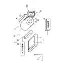
図1および図2は、本実施の形態に関する印刷装置100の構成の例を概略的に示す図である。図1および図2においては、(円筒形状、多角形状を含む)回転対称体であるワークの例としてボトル8が示され、ワークの側面の例として、ボトル8の側面80が示される。
図1および図2は、本実施の形態に関する印刷装置100の構成の例を概略的に示す図である。図1および図2においては、(円筒形状、多角形状を含む)回転対称体であるワークの例としてボトル8が示され、ワークの側面の例として、ボトル8の側面80が示される。
図示しない搬送部によって搬送されるボトル8は、ホルダ300に着脱可能に保持されることが望ましい。また、ホルダ300の形態は、図1および図2に示されるものには限られず、ボトル8を保持することができる形態であればよい。
印刷装置100は、少なくとも1つの印刷ユニット101と制御装置9とを備える。印刷ユニット101は、ボトル8の側面80に、たとえば、単色印刷を行う。印刷装置100に印刷ユニット101が複数設けられる場合には、それぞれの印刷ユニット101が互いに異なる色の単色印刷を行うことによって、多色印刷(二色印刷を含む)が実現される。
印刷装置100における印刷ユニット101は、制御装置9によってその駆動が制御される。
ここで、制御装置9は、たとえば、ハードディスクドライブ(Hard disk drive、すなわち、HDD)、ランダムアクセスメモリ(random access memory、すなわち、RAM)、リードオンリーメモリ(read only memory、すなわち、ROM)、フラッシュメモリ、揮発性または不揮発性の半導体メモリ、磁気ディスク、フレキシブルディスク、光ディスク、コンパクトディスク、ミニディスクまたはDVDなどを含むメモリ(記憶媒体)を含む記憶装置と、たとえば、当該記憶装置、外部のCD-ROM、外部のDVD-ROM、または、外部のフラッシュメモリなどに格納されたプログラムを実行する中央演算処理装置(central processing unit、すなわち、CPU)などの処理回路と、マウス、キーボード、タッチパネル、または、各種スイッチなどの、情報を入力することができる入力装置と、ディスプレイ、液晶表示装置、または、ランプなどの、情報を出力することができる出力装置とを含むことができる。
印刷ユニット101は、版ステージユニット1と、インク充填ユニット2と、転写ユニット3とを備える。また、印刷ユニット101は、硬化ユニット4を備えることができる。これらの構成は、Y軸正方向側からY軸負方向側に向けて、上記の順番で並べて配置される。
それぞれの印刷ユニット101に受け渡されるボトル8は、ホルダ300で保持された状態で転写ユニット3および硬化ユニット4に近接したり、離隔したりする。図1は、ボトル8がホルダ300で保持された状態で転写ユニット3および硬化ユニット4から離隔している状態を示す。一方で、図2は、ボトル8がホルダ300で保持された状態で転写ユニット3および硬化ユニット4に近接している状態を示す。
印刷ユニット101においては、まず、版ステージユニット1およびインク充填ユニット2によって光硬化性インクを用いるインクパターンが形成される。
そして、インクパターンが転写ユニット3へ転写される。さらに、インクパターンが転写ユニット3からボトル8の側面80へ転写される。
そして、硬化ユニット4からの光照射によって、ボトル8の側面80に転写されたインクが硬化する。なお、硬化ユニット4がボトル8の側面80におけるインクを硬化させる方法は、紫外線照射などの光照射に限られるものではなく、たとえば、熱処理などによってインクを硬化させる方法であってもよい。
ホルダ300におけるボトル8は、側面80の回転対称軸を中心として回転自在に保持される。印刷ユニット101における上記のいずれの工程も、ボトル8がホルダ300に保持された状態で実行される。
上記の工程のうち、インクパターンの形成、および、インクパターンの転写ユニット3への転写は、たとえば、ボトル8が転写ユニット3および硬化ユニット4から離隔している状態(すなわち、図1に示される状態)、または、複数の印刷ユニット101同士の間をボトル8が移動している間に実行される。
また、上記の工程のうち、インクパターンのボトル8の側面80への転写、および、インクの硬化は、ボトル8が転写ユニット3および硬化ユニット4に近接している状態(すなわち、図2に示される状態)で実行される。
印刷装置100においては、印刷ユニット101において上記の工程が実行された後、ボトル8がホルダ300に保持された状態で印刷ユニット101から搬送され、ボトル8の側面80に転写されたインクをさらに硬化させる処理(本硬化処理)が行われる。この場合、印刷ユニット101におけるインクの硬化は、単色印刷ごとの一時的な硬化として実行される。
版ステージユニット1は、ステージ11と、版12とを備える。版12は、ステージ11のZ軸正方向側の面に配置される。版12は、インクパターンを形成するための版(たとえば、凹版)である。ステージ11は、XYZ方向のいずれの方向にも、さらにZ軸周りの回転方向にも移動可能である。このような移動には、たとえば、クロスローラベアリング機構が利用される。
ステージ11は、インク充填ユニット2および転写ユニット3から見てY軸正方向側の位置からY軸負方向に可動であって、インク充填ユニット2を経由して転写ユニット3に近接可能である。ステージ11は、Y軸正方向にも可動であって、転写ユニット3から離隔可能である。
インク充填ユニット2は、ノズル21と、インク供給部22とを備える。インク供給部22は、ノズル21へ光硬化性インク(以下、単に「インク」とも称する)を供給する。
光硬化性インクには、たとえば、顕色剤としての顔料、重合によって強固なポリマー層を構成するポリマー材料(モノマーおよびオリゴマーの少なくとも一方を含む)、および、光照射を受けて化学変化することで生じる活性種によってポリマー材料の重合反応を促進する光重合開始剤が含まれる。
ステージ11がY軸負方向に移動してノズル21が版12とZ軸方向において対向する際、ノズル21へ供給されたインクは、ノズル21の下端に設けられた吐出口から吐出され、さらに、版12のZ軸正方向側の面(以下「上面」とも称する)に塗布される。
たとえば、版12が凹版である場合、ドクターブレード(図示しない)によって版12の上面が擦られる。これによって版12の凹部にインクが充填され、かつ、凹部以外のインクが除去されるため、版12にインクパターンが形成される。
インクパターンが形成された版12は、さらにY軸負方向に移動して転写ユニット3に近接する。
転写ユニット3は、ブランケットロール30と、モータ33とを備える。モータ33は、制御装置9の制御によって駆動し、ブランケットロール30を回転させる。
ブランケットロール30は、ブランケット胴31と、ブランケット32とを備える。ブランケット胴31は、たとえば、金属製の円筒である。ブランケット32は、ブランケット胴31の表面に巻き付けられる。ブランケット32は、円筒状の形状を有する。ブランケット32の材料としては、基材に押圧された際に、基材の形状に追従して多少変形するものであることが望ましく、たとえば、シリコンゴム、PDMS(ポリジメチルシロキサン)、NBR(アクリロニトリル・ブタジエンゴム)またはEPDM(エチレン・プロピレン・ジエンゴム)などが想定される。
ブランケットロール30は、図1および図2において、一点鎖線で示される回転軸を中心として回転自在に支持される。
ブランケット32の表面は、インクを付着させかつ固定させることができる。ステージ11がY軸負方向に移動してブランケットロール30が版12とZ軸方向において対向する際、ブランケット32の表面が版12の上面に接触する。そして、版12に形成されていたインクパターンが、ブランケット32の表面に移行する(転写される)。
ボトル8が転写ユニット3に近接し、ボトル8の側面80がブランケット32に接触し、さらに、ブランケット32と側面80とが接触しつつ互いに反対方向に回転する。
これによって、ブランケット32に移行されたインクパターンは、さらに、側面80に転写される。ボトル8の側面80に生じ得る凹凸の高さが、ブランケット32の厚さよりも小さいことは、かかる転写の観点から望ましい。
ブランケット32は、ボトル8の側面80に転写されるインクパターンを一時的に付着および固定させる中間転写体として機能する。ブランケット32は、弾性を有する樹脂材料、たとえば、シリコン樹脂で形成される。
かかる転写においてボトル8が1周以上回転する場合、ボトル8の側面80のインクパターンがブランケット32へ転写されてしまうこと(以下「逆転写」とも称する)が想定される。逆転写は、ボトル8の側面80のインクパターンを乱す。逆転写が低減されるように、側面80に転写されたインクの粘度は、たとえば、以下のようにして増大されることが望ましい。
ブランケット32からインクパターンの転写を受けた直後のボトル8の側面80に向けて、硬化ユニット4から光(紫外線)が照射される。印刷装置100に印刷ユニット101が複数設けられる場合、インクに含まれるポリマー材料の一部を重合させてインクの粘度を増大させるが、インク全体を硬化させるには至らない条件で、硬化ユニット4から光(紫外線)が照射される。かかる条件は、たとえば、当該光の強度によって設定される。
インクの粘度が増大することでボトル8の側面80からブランケット32への付着性が低下し、逆転写が低減される。かかる付着性の低下は、ホルダ300の汚染を回避する観点でも望ましい。
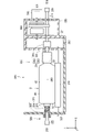
図3は、ボトル8を保持している状態のホルダ300の構成の例を概略的に示す側面図である。図3に例が示されるように、ホルダ300は、X軸方向に沿う回転軸線309のまわりで回転自在にボトル8を保持する。ボトル8は、回転対称軸800が回転軸線309に沿う横向き姿勢で、ホルダ300によって保持される。以下では、回転軸線309についての周方向および径方向をそれぞれ単に周方向および径方向とも称する。
図3に例が示されるように、ホルダ300は、保持機構310と、保持本体部330とを備えている。
保持機構310は、回転軸線309のまわりで回転自在にボトル8の一端を保持する。保持機構310によって保持されるボトル8の一端は、回転対称軸800におけるボトル8の一方側の端部である。
保持機構310は、回転保持部311を備える。回転保持部311は、回転軸線309のまわりで回転自在に支持されたシャフト部312と、シャフト部312の端部に連結された保持部材313とを備える。
保持部材313は、ボトル8の一端を着脱可能に保持する。保持部材313がボトル8の一端を保持している状態で、回転保持部311が回転軸線309のまわりで回転することによって、回転保持部311によって保持されたボトル8も回転軸線309のまわりで回転する。
図3の例では、ホルダ300は、回転駆動機構500を備えている。回転駆動機構500は、制御装置9の制御によって、回転保持部311を回転軸線309のまわりで回転させる駆動力を回転保持部311に与える。回転駆動機構500はモータ501を備えており、モータ501の回転力が回転保持部311に伝達されて、回転保持部311が回転軸線309のまわりで回転する。
図3に示される例では、回転駆動機構500は、動力伝達機構380を介して回転保持部311に回転力を伝達する。動力伝達機構380は、ギア、プーリまたはベルトなどの種々の機械要素を含んでおり、回転駆動機構500からの回転力を回転保持部311に伝達する。動力伝達機構380は、たとえば、クラッチを含んでいてもよく、回転駆動機構500からの回転力を回転保持部311に伝達する接続状態と、回転駆動機構500からの回転力を回転保持部311に伝達しない遮断状態とが切り替えられてもよい。
シャフト部312は、シャフト314を備える。シャフト314は回転軸線309に沿って設けられており、保持本体部330に対して回転軸線309のまわりで回転可能に支持されている。
保持本体部330は、平板状の基台333と、支持部331と、支持部332とを備える。基台333は、Z軸方向に垂直な平板状の形状を有する。支持部331は、X軸正方向側で基台333からZ軸正方向に設けられている。支持部332は、支持部331からX軸負方向に離間する位置で、基台333からZ軸正方向に設けられている。
シャフト314のX軸負方向側の端部には保持部材313が設けられ、シャフト314のX軸正方向側の端部には摘み部材319が設けられる。
保持部材313は、ボトル8の一端である口元部81を着脱可能に保持する。ボトル8は、口元部81と、胴部82と、底部83とを備える。胴部82は円筒形状を有しており、その外側面である側面80は、回転対称軸800について回転対称である。底部83は、胴部82のX軸負方向側の開口を塞いでいる。口元部81は胴部82のX軸正方向側の開口に連結されており、胴部82から遠ざかるにつれて、径が小さくなる先細の円筒形状を有している。口元部81の先端の外側面には、雄ねじ部が形成されている。保持部材313は、ボトルキャップと同様の形状を有している。
口元部81と保持部材313とが連結されていない状態において、作業者はボトル8を保持してボトル8の回転を規制しながら、口元部81と保持部材313とが互いに螺合する方向へ、摘み部材319を回転させる。当該回転によって口元部81と保持部材313とが螺合する。そして、当該螺合によって口元部81と保持部材313とが連結される。当該連結によってシャフト314とボトル8とがX軸方向において連結される。
保持部材313とボトル8とが連結された状態において、作業者がボトル8の回転を規制しながら摘み部材319を、口元部81と保持部材313との螺合を解除する方向へ回転させる。このような回転によって、口元部81から保持部材313が取り外され、シャフト314とボトル8との間の連結が解除される。
図3に示されるように、シャフト部312は、自動調心軸受315を備えることができる。自動調心軸受315は、シャフト314を回転自在に保持本体部330に支持する。具体的には、シャフト314は自動調心軸受315の内輪に貫通固定されており、自動調心軸受315の外輪が保持本体部330(支持部331)に対して固定される。なお、自動調心軸受315の外輪と支持部331との固定は、図3では図示省略されている。自動調心軸受315の内輪は、外輪に対して回転自在であるとともに傾斜自在でもある。したがって、シャフト314が回転軸線309に対して撓んでも、自動調心軸受315の内輪がシャフト314の撓みに応じて外輪に対して傾斜変位するので、シャフト314が撓んだまま回転することができる。
図3に示されるように、ホルダ300は、バックアップローラ370を備えることができる。バックアップローラ370は、ボトル8よりも径方向外側に配置されており、ボトル8の側面80と接触する。図3に示される例では、一つのバックアップローラ370のみが示されているが、複数のバックアップローラが設けられてもよい。複数のバックアップローラは、周方向の互いに異なる位置でボトル8の側面80に接触する。
図3に示されるように、ホルダ300は、保持機構320を備えることができる。保持機構320は、回転保持部321を備える。回転保持部321は、ボトル8の他端(ここでは底部83)を回転軸線309のまわりで回転自在にX軸正方向側に付勢する。
回転保持部321は、シャフト322と、接触部材323と、付勢部材324とを備える。
シャフト322は、回転軸線309に沿って設けられており、シャフト部312の軸線(つまり、シャフト314の軸線)と一致するように配置される。シャフト322は、支持部332に対して回転軸線309のまわりで回転自在に支持されるとともに、支持部332に対してX軸方向に沿って移動可能に支持される。
シャフト322のX軸正方向側の端部には、ボトル8の底部83と接触する接触部材323が設けられている。シャフト322のX軸負方向側の端部には、摘み部材325が設けられている。
回転軸線309に沿って見た場合の接触部材323のサイズは、シャフト322よりも大きい。付勢部材324は、接触部材323と支持部332のX軸正方向側の壁面との間に設けられている。付勢部材324は、接触部材323をボトル8の底部83側に付勢する。たとえば、付勢部材324はバネを含み、当該バネがシャフト322に挿入される。付勢部材324が接触部材323を底部83側に付勢することによって、付勢力は接触部材323を介してボトル8の底部83に伝達される。つまり、接触部材323がボトル8の底部83を口元部81側に付勢する。これによって、ボトル8はX軸方向において保持機構310および保持機構320によって挟持される。
作業者は、付勢部材324による付勢力に抗いながら摘み部材325をX軸負方向に移動させて、接触部材323を底部83から離すことができる。接触部材323を底部83から離すことは、口元部81から保持部材313を取り外す処理を容易にする。
図4は、複数のバックアップローラを用いてボトル8を保持している状態の例を示す図である。図4の例では、複数のバックアップローラとして、バックアップローラ370aおよびバックアップローラ370bがホルダ300に設けられている。
バックアップローラ370aおよびバックアップローラ370bは、回転軸線309に平行なX軸方向を軸方向とする回転体形状を有し、支持部331と支持部332とに対して回転自在に支持されている。バックアップローラ370aおよびバックアップローラ370bは、回転軸線309と平行な軸線のまわりで回転自在に支持される。
図4の例では、バックアップローラ370aは、ボトル8の側面80を印刷ユニット101のブランケット32に押し当てるように、ボトル8を挟んでブランケット32の反対側、すなわち、Y軸負方向側に配置されている。バックアップローラ370aがボトル8の側面80にY軸負方向側から接触することによって、Y軸負方向へのボトル8の変位を規制する。
また、バックアップローラ370bは、Z軸方向においてバックアップローラ370aよりも低い位置に配置されている。バックアップローラ370bは、ボトル8の側面80にZ軸負方向から接触することによって、Z軸負方向、すなわち、重力方向へのボトル8の変位を規制する。
以上のように、ボトル8の回転時においてボトル8の側面80がバックアップローラ370(または、バックアップローラ370aおよびバックアップローラ370b)に接触することによって、ボトル8の胴部82の回転対称軸800が回転軸線309に沿うように、ボトル8の保持姿勢が調整される。言い換えれば、バックアップローラによってボトル8の変位を抑制することができる。なお、バックアップローラは、3つ以上設けられていてもよい。複数のバックアップローラが回転軸線309を中心とする仮想円A1上に配置されることによって、ボトル8の変位を効果的に抑制することができる。
図5は、印刷装置100を制御する制御系統を模式的に示す図である。図5に例が示されるように、印刷装置100における制御装置9は、印刷装置100におけるそれぞれの駆動部の駆動を制御する。
具体的には、制御装置9は、印刷ユニット101におけるステージ11の移動、インク供給部22からのインク供給動作、および、ブランケットロール30を回転させるためのモータ33の駆動などを制御する。また、制御装置9は、ホルダ300における回転保持部311を回転させるためのモータ501の駆動などを制御する。
<印刷装置の動作について>
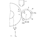
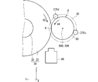
次に、図6および図7を参照しつつ、本実施の形態に関する印刷装置の動作を説明する。図6および図7は、本実施の形態に関するブランケットロール30およびボトル8の回転の様子を概略的に示す図である。
次に、図6および図7を参照しつつ、本実施の形態に関する印刷装置の動作を説明する。図6および図7は、本実施の形態に関するブランケットロール30およびボトル8の回転の様子を概略的に示す図である。
図6においては、ブランケットロール30とボトル8とが接触しており、たとえば、ブランケットロール30におけるインクパターンがボトル8の側面80に転写される動作に対応している。
制御装置9の制御でモータ33が駆動することによって(図1および図2を参照)、ブランケットロール30が回転する。この場合のブランケットロール30の外周面の周方向の速度V1は、制御装置9の制御によって調整可能である。図6においては、速度V1の方向は、ブランケットロール30とボトル8とが接触する位置(接触部P)において、Z軸正方向に向く方向である。
また、制御装置9の制御でモータ501が駆動することによって(図3を参照)、ホルダ300においてボトル8を保持する回転保持部311が回転する。回転保持部311の回転に伴って、回転保持部311に保持されているボトル8も回転する。この場合のボトル8の外周面(側面80)の周方向の速度V2は、制御装置9の制御によって調整可能である。図6においては、速度V2の方向は、ブランケットロール30とボトル8とが接触する位置(接触部P)において、Z軸正方向に向く方向である。
この際、制御装置9は、ボトル8の周方向の速度V2が、摩擦抵抗などがなければブランケットロール30の周方向の速度V1よりも速くなるように、対応するそれぞれの駆動部(すなわち、モータ501およびモータ33)の出力を調整する。
ただし、ブランケットロール30の外周面とボトル8の外周面とは接触部Pにおいて互いに接触し、かつ、接触部Pにおいて静止摩擦力が生じて滑らないものとする。言い換えれば、制御装置9は、それぞれの駆動部(すなわち、モータ501およびモータ33)の出力を、接触部Pにおける静止摩擦力、さらにはブランケットロール30の外周面の変形(たとえば、ひずみまたは伸縮)などによって、ブランケットロール30とボトル8とが互いの回転方向においてずれない範囲で調整する。
接触部Pにおいてブランケットロール30とボトル8とが互いの回転方向においてずれない範囲としては、たとえば、ブランケットロール30の周方向の速度V1を基準として、ボトル8の周方向の速度V2が1%以上、かつ、5%以下で速くなる(すなわち、速度V1に対して、速度V2が101%以上、かつ、105%以下となる)範囲が想定される。
上記のように、ボトル8の周方向の速度V2がブランケットロール30の周方向の速度V1よりも速いことによって、回転するボトル8は、回転方向とは反対側に摩擦抵抗を受ける。すなわち、回転するボトル8の外周面(側面80)は、ボトル8の周方向の速度V2よりも僅かに遅い周方向の速度となるように調整されたブランケットロール30の外周面に、回転方向とは反対側に引っ張られる。
そうすると、ブランケットロール30の回転にしたがってボトル8が回転する場合に生じ得る、ボトル8の位置がブランケットロール30の回転方向に引っ張られてずれる(図6の場合では、Z軸正方向にずれる)という現象を抑制することができる。
また、図6の例に示されるように、ボトル8の回転方向における接触部Pよりも上流側(図6の場合では、Z軸負方向側)に、バックアップローラ370bが設けられていてもよい。このような位置にバックアップローラ370bが配置されることによって、ボトル8が、ブランケットロール30の外周面との間の摩擦抵抗によって回転方向とは反対側に引っ張られることによってずれる(図6の場合では、Z軸負方向にずれる)ことをも抑制することができる。
さらに、ボトル8の、ブランケットロール30と接触する側とは反対側(図6の場合では、Y軸負方向側)に、バックアップローラ370aが設けられてもよい。このような位置にバックアップローラ370aが配置されることによって、ボトル8が、ブランケットロール30の外周面との接触によってY軸負方向に押し出されるようにずれることをも抑制することができる。
また、図6の例に示されるように、ボトル8の回転方向における接触部Pよりも下流側(図6の場合では、Z軸正方向側)に、硬化ユニット4が設けられていてもよい。このような位置に硬化ユニット4が配置されることによって、接触部Pにおいてボトル8に印刷された直後のインクを紫外線照射などによって硬化させることができる。そうすると、インクがブランケットロール30の外周面に再付着することを抑制することができる。
なお、ボトル8がブランケットロール30の外周面との間の摩擦抵抗によって回転方向とは反対側に引っ張られるため、接触部Pの下流側にはバックアップローラのようなボトル8の位置ずれを抑制するための構成が不要となる。そのため、ボトル8の回転方向における接触部Pよりも下流側に、硬化ユニット4を配置するスペースを確保することができる。
図7においても、ブランケットロール30とボトル8とが接触しており、たとえば、ブランケットロール30におけるインクパターンがボトル8の側面80に転写される動作に対応している。
制御装置9の制御でモータ33が駆動することによって(図1および図2を参照)、ブランケットロール30が回転する。この場合のブランケットロール30の外周面の周方向の速度V3は、制御装置9の制御によって調整可能である。図7においては図6の場合とは異なり、速度V3の方向は、ブランケットロール30とボトル8とが接触する位置(接触部P)において、Z軸負方向に向く方向である。
また、制御装置9の制御でモータ501が駆動することによって(図3を参照)、ホルダ300においてボトル8を保持する回転保持部311が回転する。回転保持部311の回転に伴って、回転保持部311に保持されているボトル8も回転する。この場合のボトル8の外周面(側面80)の周方向の速度V4は、制御装置9の制御によって調整可能である。図7においては図6の場合とは異なり、速度V4の方向は、ブランケットロール30とボトル8とが接触する位置(接触部P)において、Z軸負方向に向く方向である。
この際、制御装置9は、ボトル8の周方向の速度V4が、摩擦抵抗などがなければブランケットロール30の周方向の速度V3よりも速くなるように、対応するそれぞれの駆動部(すなわち、モータ501およびモータ33)の出力を調整する。
ただし、ブランケットロール30の外周面とボトル8の外周面とは接触部Pにおいて互いに接触し、かつ、接触部Pにおいて静止摩擦力が生じて滑らないものとする。
上記のように、ボトル8の周方向の速度V4がブランケットロール30の周方向の速度V3よりも速いことによって、回転するボトル8は、回転方向とは反対側に摩擦抵抗を受ける。すなわち、回転するボトル8の外周面(側面80)は、ボトル8の周方向の速度V4よりも僅かに遅い周方向の速度となるように調整されたブランケットロール30の外周面に、回転方向とは反対側に引っ張られる。
そうすると、ブランケットロール30の回転にしたがってボトル8が回転する場合に生じ得る、ボトル8の位置がブランケットロール30の回転方向に引っ張られてずれる(図7の場合では、Z軸負方向にずれる)という現象を抑制することができる。
また、図7の例に示されるように、ボトル8の回転方向における接触部Pよりも上流側(図7の場合では、Z軸正方向側)に、バックアップローラ370dが設けられていてもよい。このような位置にバックアップローラ370dが配置されることによって、ボトル8が、ブランケットロール30の外周面との間の摩擦抵抗によって回転方向とは反対側に引っ張られることによってずれる(図6の場合では、Z軸正方向にずれる)ことをも抑制することができる。
さらに、ボトル8の、ブランケットロール30と接触する側とは反対側(図6の場合では、Y軸負方向側)に、バックアップローラ370cが設けられてもよい。このような位置にバックアップローラ370cが配置されることによって、ボトル8が、ブランケットロール30の外周面との接触によってY軸負方向に押し出されるようにずれることをも抑制することができる。
また、図7の例に示されるように、ボトル8の回転方向における接触部Pよりも下流側(図6の場合では、Z軸負方向側)に、ボトル8の側面に転写されたインクを硬化させるための硬化ユニット4Aが設けられていてもよい。このような位置に硬化ユニット4Aが配置されることによって、接触部Pにおいてボトル8に印刷された直後のインクを紫外線照射などによって硬化させることができる。そうすると、インクがブランケットロール30の外周面に再付着することを抑制することができる。
<以上に記載された実施の形態によって生じる効果について>
次に、以上に記載された実施の形態によって生じる効果の例を示す。なお、以下の説明においては、以上に記載された実施の形態に例が示された具体的な構成に基づいて当該効果が記載されるが、同様の効果が生じる範囲で、本願明細書に例が示される他の具体的な構成と置き換えられてもよい。すなわち、以下では便宜上、対応づけられる具体的な構成のうちのいずれか1つのみが代表して記載される場合があるが、代表して記載された具体的な構成が対応づけられる他の具体的な構成に置き換えられてもよい。
次に、以上に記載された実施の形態によって生じる効果の例を示す。なお、以下の説明においては、以上に記載された実施の形態に例が示された具体的な構成に基づいて当該効果が記載されるが、同様の効果が生じる範囲で、本願明細書に例が示される他の具体的な構成と置き換えられてもよい。すなわち、以下では便宜上、対応づけられる具体的な構成のうちのいずれか1つのみが代表して記載される場合があるが、代表して記載された具体的な構成が対応づけられる他の具体的な構成に置き換えられてもよい。
以上に記載された実施の形態によれば、印刷装置は、ホルダ300と、ブランケットロール30と、第1の駆動源と、第2の駆動源と、制御装置9とを備える。ここで、第1の駆動源は、たとえば、モータ501などに対応する。また、第2の駆動源は、たとえば、モータ33などに対応する。ホルダ300は、回転対称体であるワークを回転対称軸まわりに回転可能に保持する。ここで、ワークは、たとえば、ボトル8などに対応する。ブランケットロール30は、ホルダ300において回転するボトル8に接触する。また、ブランケットロール30は、ボトル8とともに回転することによって、ボトル8に印刷を行う。モータ501は、ホルダ300に保持されたボトル8を回転させる。モータ33は、ブランケットロール30を回転させる。制御装置9は、モータ501の駆動とモータ33の駆動とを制御する。制御装置9は、ボトル8とブランケットロール30との接触部Pにおけるボトル8の周方向の速度V2(または速度V4)が接触部Pにおけるブランケットロール30の周方向の速度V1(または速度V3)よりも速くなるように、モータ501の駆動およびモータ33の駆動を制御する。
このような構成によれば、ボトル8の周方向の速度がブランケットロール30の周方向の速度よりも速いため、回転するボトル8は、回転方向とは反対側に摩擦抵抗を受ける。そのため、ボトル8への印刷に際し、ボトル8の位置ずれを抑制することができる。すなわち、回転するボトル8の外周面が、ボトル8の周方向の速度V2よりも僅かに遅い周方向の速度となるように調整されたブランケットロール30の外周面に、回転方向とは反対側に引っ張られるため、ボトル8の位置がブランケットロール30の回転方向に引っ張られてずれるという現象を抑制することができる。また、ボトル8自体が自律的に回転することによって、ボトル8がブランケットロール30の回転にしたがって回転する場合よりも、ボトル8の回転の再現性が向上する。
なお、上記の構成に本願明細書に例が示された他の構成を適宜追加した場合、すなわち、上記の構成としては言及されなかった本願明細書中の他の構成が適宜追加された場合であっても、同様の効果を生じさせることができる。
また、以上に記載された実施の形態によれば、制御装置9は、接触部Pにおけるボトル8の周方向の速度V2(または速度V4)が、接触部Pにおけるブランケットロール30の周方向の速度V1(または速度V3)を基準として1%以上、かつ、5%以下速くなるように、モータ501の駆動およびモータ33の駆動を制御する。このような構成によれば、ブランケットロール30とボトル8とが互いの回転方向においてずれない範囲で、ボトル8の外周面に摩擦抵抗を生じさせることができる。
また、以上に記載された実施の形態によれば、印刷装置は、ボトル8の回転方向の接触部Pよりも上流側に位置し、かつ、ボトル8に接触するためのバックアップローラ370b(またはバックアップローラ370d)を備える。このような構成によれば、ボトル8が、ブランケットロール30の外周面との間の摩擦抵抗によって回転方向とは反対側に引っ張られることによってずれる(図6の場合では、Z軸負方向にずれる)ことをも抑制することができる。
また、以上に記載された実施の形態によれば、印刷装置は、ボトル8の回転方向の接触部Pよりも下流側に位置し、かつ、ボトル8に印刷されたインクを硬化させるための硬化ユニット4(または硬化ユニット4A)を備える。このような構成によれば、接触部Pにおいてボトル8に印刷された直後のインクを紫外線照射などによって硬化させることができる。そうすると、インクがブランケットロール30の外周面に再付着することを抑制することができる。
以上に記載された実施の形態によれば、印刷方法において、回転対称体であるボトル8を回転対称軸まわりに回転可能に保持する。そして、ブランケットロール30を、回転するボトル8に接触させつつボトル8とともに回転させることによって、ボトル8に印刷を行う。ここで、ボトル8に印刷を行う工程は、ボトル8とブランケットロール30との接触部Pにおけるボトル8の周方向の速度V2(または速度V4)が接触部Pにおけるブランケットロール30の周方向の速度V1(または速度V3)よりも速くなるように、ボトル8を回転させるためのモータ501の駆動とブランケットロール30を回転させるためのモータ33の駆動とを制御しつつ、ボトル8に印刷を行う工程である。
このような構成によれば、ボトル8の周方向の速度がブランケットロール30の周方向の速度よりも速いため、回転するボトル8は、回転方向とは反対側に摩擦抵抗を受ける。そのため、ボトル8への印刷に際し、ボトル8の位置ずれを抑制することができる。
なお、特段の制限がない場合には、それぞれの処理が行われる順序は変更することができる。
また、上記の構成に本願明細書に例が示された他の構成を適宜追加した場合、すなわち、上記の構成としては言及されなかった本願明細書中の他の構成が適宜追加された場合であっても、同様の効果を生じさせることができる。
<以上に記載された実施の形態の変形例について>
以上に記載された実施の形態では、それぞれの構成要素の材質、材料、寸法、形状、相対的配置関係または実施の条件などについても記載する場合があるが、これらはすべての局面においてひとつの例であって、限定的なものではないものとする。
以上に記載された実施の形態では、それぞれの構成要素の材質、材料、寸法、形状、相対的配置関係または実施の条件などについても記載する場合があるが、これらはすべての局面においてひとつの例であって、限定的なものではないものとする。
したがって、例が示されていない無数の変形例、および、均等物が、本願明細書に開示される技術の範囲内において想定される。たとえば、少なくとも1つの構成要素を変形する場合、追加する場合または省略する場合が含まれるものとする。
また、以上に記載された実施の形態において、特に指定されずに材料名などが記載された場合は、矛盾が生じない限り、当該材料に他の添加物が含まれた、たとえば、合金などが含まれるものとする。
また、以上に記載された実施の形態で記載されたそれぞれの構成要素は、ソフトウェアまたはファームウェアとしても、それと対応するハードウェアとしても想定され、その双方の概念において、それぞれの構成要素は「部」または「処理回路」(circuitry)などと称される。
1 版ステージユニット
2 インク充填ユニット
3 転写ユニット
4,4A 硬化ユニット
8 ボトル
9 制御装置
11 ステージ
12 版
21 ノズル
22 インク供給部
30 ブランケットロール
31 ブランケット胴
32 ブランケット
33,501 モータ
80 側面
81 口元部
82 胴部
83 底部
100 印刷装置
101 印刷ユニット
300 ホルダ
309 回転軸線
310,320 保持機構
311,321 回転保持部
312 シャフト部
313 保持部材
314,322 シャフト
315 自動調心軸受
319,325 摘み部材
323 接触部材
324 付勢部材
330 保持本体部
331,332 支持部
333 基台
370,370a,370b,370c,370d バックアップローラ
380 動力伝達機構
500 回転駆動機構
800 回転対称軸
2 インク充填ユニット
3 転写ユニット
4,4A 硬化ユニット
8 ボトル
9 制御装置
11 ステージ
12 版
21 ノズル
22 インク供給部
30 ブランケットロール
31 ブランケット胴
32 ブランケット
33,501 モータ
80 側面
81 口元部
82 胴部
83 底部
100 印刷装置
101 印刷ユニット
300 ホルダ
309 回転軸線
310,320 保持機構
311,321 回転保持部
312 シャフト部
313 保持部材
314,322 シャフト
315 自動調心軸受
319,325 摘み部材
323 接触部材
324 付勢部材
330 保持本体部
331,332 支持部
333 基台
370,370a,370b,370c,370d バックアップローラ
380 動力伝達機構
500 回転駆動機構
800 回転対称軸
Claims (6)
- 回転対称体であるワークを回転対称軸まわりに回転可能に保持するためのホルダと、
前記ホルダにおいて回転する前記ワークに接触しつつ前記ワークとともに回転することによって、前記ワークに印刷を行うためのブランケットロールと、
前記ホルダに保持された前記ワークを回転させるための第1の駆動源と、
前記ブランケットロールを回転させるための第2の駆動源と、
前記第1の駆動源の駆動と前記第2の駆動源の駆動とを制御するための制御装置とを備え、
前記制御装置は、前記ワークと前記ブランケットロールとの接触部における前記ワークの周方向の速度が前記接触部における前記ブランケットロールの周方向の速度よりも速くなるように、前記第1の駆動源の駆動および前記第2の駆動源の駆動を制御する、
印刷装置。 - 請求項1に記載の印刷装置であり、
前記制御装置は、前記接触部における前記ワークの周方向の速度が、前記接触部における前記ブランケットロールの周方向の速度を基準として1%以上、かつ、5%以下速くなるように、前記第1の駆動源の駆動および前記第2の駆動源の駆動を制御する、
印刷装置。 - 請求項1または2に記載の印刷装置であり、
前記ワークの回転方向の前記接触部よりも上流側に位置し、かつ、前記ワークに接触するためのバックアップローラをさらに備える、
印刷装置。 - 請求項1から3のうちのいずれか1つに記載の印刷装置であり、
前記ワークの回転方向の前記接触部よりも下流側に位置し、かつ、前記ワークに印刷されたインクを硬化させるための硬化ユニットをさらに備える、
印刷装置。 - 回転対称体であるワークを回転対称軸まわりに回転可能に保持する工程と、
ブランケットロールを、回転する前記ワークに接触させつつ前記ワークとともに回転させることによって、前記ワークに印刷を行う工程とを備え、
前記ワークに印刷を行う工程は、前記ワークと前記ブランケットロールとの接触部における前記ワークの周方向の速度が前記接触部における前記ブランケットロールの周方向の速度よりも速くなるように、前記ワークを回転させるための第1の駆動源の駆動と前記ブランケットロールを回転させるための第2の駆動源の駆動とを制御しつつ、前記ワークに印刷を行う工程である、
印刷方法。 - 請求項5に記載の印刷方法であり、
前記ワークに印刷を行う工程は、前記接触部における前記ワークの周方向の速度が、前記接触部における前記ブランケットロールの周方向の速度を基準として1%以上、かつ、5%以下速くなるように、前記第1の駆動源の駆動および前記第2の駆動源の駆動を制御しつつ、前記ワークに印刷を行う工程である、
印刷方法。
Applications Claiming Priority (2)
| Application Number | Priority Date | Filing Date | Title |
|---|---|---|---|
| JP2020181620A JP2022072268A (ja) | 2020-10-29 | 2020-10-29 | 印刷装置、および、印刷方法 |
| JP2020-181620 | 2020-10-29 |
Publications (1)
| Publication Number | Publication Date |
|---|---|
| WO2022092016A1 true WO2022092016A1 (ja) | 2022-05-05 |
Family
ID=81382533
Family Applications (1)
| Application Number | Title | Priority Date | Filing Date |
|---|---|---|---|
| PCT/JP2021/039274 Ceased WO2022092016A1 (ja) | 2020-10-29 | 2021-10-25 | 印刷装置、および、印刷方法 |
Country Status (3)
| Country | Link |
|---|---|
| JP (1) | JP2022072268A (ja) |
| TW (1) | TWI795047B (ja) |
| WO (1) | WO2022092016A1 (ja) |
Families Citing this family (1)
| Publication number | Priority date | Publication date | Assignee | Title |
|---|---|---|---|---|
| JP2024003990A (ja) * | 2022-06-28 | 2024-01-16 | 富士フイルムビジネスイノベーション株式会社 | 画像形成装置 |
Citations (3)
| Publication number | Priority date | Publication date | Assignee | Title |
|---|---|---|---|---|
| JPS62183348A (ja) * | 1986-02-07 | 1987-08-11 | Kiyokutoo Internatl:Kk | 印刷方法及び装置 |
| JP2020019145A (ja) * | 2018-07-30 | 2020-02-06 | 株式会社Screenホールディングス | 歪み補正方法および歪み補正装置 |
| WO2020110618A1 (ja) * | 2018-11-29 | 2020-06-04 | 株式会社Screenホールディングス | ワーク保持装置、印刷システムおよび印刷方法 |
Family Cites Families (5)
| Publication number | Priority date | Publication date | Assignee | Title |
|---|---|---|---|---|
| KR101332145B1 (ko) * | 2011-12-14 | 2013-11-21 | 삼성전기주식회사 | 그라비어 인쇄장치 |
| JP6189022B2 (ja) * | 2012-07-18 | 2017-08-30 | 株式会社コムラテック | フレキソ印刷用印刷装置 |
| EP3012104A4 (en) * | 2013-06-20 | 2017-04-19 | Komori Corporation | Intaglio printing machine and intaglio printing method |
| US10124572B2 (en) * | 2014-09-17 | 2018-11-13 | Komori Corporation | Method and device for adjusting contact pressure of intaglio printer wiping roller |
| CN111065592B (zh) * | 2017-09-19 | 2022-04-26 | 住友重机械工业株式会社 | 卷材处理系统及控制方法 |
-
2020
- 2020-10-29 JP JP2020181620A patent/JP2022072268A/ja active Pending
-
2021
- 2021-10-22 TW TW110139228A patent/TWI795047B/zh active
- 2021-10-25 WO PCT/JP2021/039274 patent/WO2022092016A1/ja not_active Ceased
Patent Citations (3)
| Publication number | Priority date | Publication date | Assignee | Title |
|---|---|---|---|---|
| JPS62183348A (ja) * | 1986-02-07 | 1987-08-11 | Kiyokutoo Internatl:Kk | 印刷方法及び装置 |
| JP2020019145A (ja) * | 2018-07-30 | 2020-02-06 | 株式会社Screenホールディングス | 歪み補正方法および歪み補正装置 |
| WO2020110618A1 (ja) * | 2018-11-29 | 2020-06-04 | 株式会社Screenホールディングス | ワーク保持装置、印刷システムおよび印刷方法 |
Also Published As
| Publication number | Publication date |
|---|---|
| TW202216474A (zh) | 2022-05-01 |
| TWI795047B (zh) | 2023-03-01 |
| JP2022072268A (ja) | 2022-05-17 |
Similar Documents
| Publication | Publication Date | Title |
|---|---|---|
| JP4530367B2 (ja) | 中空円筒状印刷基材 | |
| US8783853B2 (en) | Layer forming device, image forming apparatus, and computer readable medium | |
| KR100782378B1 (ko) | 패턴 형성장치 및 방법 | |
| JP2022072268A (ja) | 印刷装置、および、印刷方法 | |
| AU2016248085A1 (en) | Variable printing process using flexible secondary plates and specialty inks | |
| TWI720691B (zh) | 工件保持裝置、印刷系統及印刷方法 | |
| JP6391709B2 (ja) | ナノ構造を型押しする方法及び装置 | |
| KR101102027B1 (ko) | 롤임프린트 장치 | |
| JP2007210332A (ja) | 液体供給を制御する装置および方法 | |
| JP5116623B2 (ja) | 円筒状印刷原版成形装置 | |
| US8408693B2 (en) | Method for transferring textured surface to curable gel ink | |
| JP2010076387A (ja) | 円筒状印刷原版成形装置 | |
| JP2010115792A (ja) | レーザー彫刻用円筒状印刷原版の製造方法 | |
| WO2022091921A1 (ja) | 印刷装置、および、印刷方法 | |
| JP2010115793A (ja) | レーザー彫刻用円筒状印刷原版の製造方法 | |
| JP2010076381A (ja) | レーザー彫刻用円筒状印刷原版の製造方法 | |
| JP5403893B2 (ja) | 弾性ローラの製造装置および製造方法 | |
| KR101847305B1 (ko) | 코팅 장치 | |
| JP5427749B2 (ja) | 弾性ローラの製造方法 | |
| WO2023209945A1 (ja) | 印刷装置、及び印刷物の製造方法 | |
| WO2022044455A1 (ja) | 回転位置調整装置および印刷システム | |
| JP2009098519A (ja) | 弾性ローラの製造装置および製造方法 | |
| JP2011112871A (ja) | 印刷装置および印刷方法 | |
| Mariappan et al. | Plate to Roll Apparatus for Flexography Using Nanoporous Stamps | |
| JP3405559B2 (ja) | ドラムチャッキング装置 |
Legal Events
| Date | Code | Title | Description |
|---|---|---|---|
| 121 | Ep: the epo has been informed by wipo that ep was designated in this application |
Ref document number: 21886134 Country of ref document: EP Kind code of ref document: A1 |
|
| NENP | Non-entry into the national phase |
Ref country code: DE |
|
| 122 | Ep: pct application non-entry in european phase |
Ref document number: 21886134 Country of ref document: EP Kind code of ref document: A1 |