WO2022091997A1 - 二重容器 - Google Patents
二重容器 Download PDFInfo
- Publication number
- WO2022091997A1 WO2022091997A1 PCT/JP2021/039222 JP2021039222W WO2022091997A1 WO 2022091997 A1 WO2022091997 A1 WO 2022091997A1 JP 2021039222 W JP2021039222 W JP 2021039222W WO 2022091997 A1 WO2022091997 A1 WO 2022091997A1
- Authority
- WO
- WIPO (PCT)
- Prior art keywords
- inner bag
- outer shell
- mouth
- container
- upper holding
- Prior art date
- Legal status (The legal status is an assumption and is not a legal conclusion. Google has not performed a legal analysis and makes no representation as to the accuracy of the status listed.)
- Ceased
Links
Images



Classifications
-
- B—PERFORMING OPERATIONS; TRANSPORTING
- B65—CONVEYING; PACKING; STORING; HANDLING THIN OR FILAMENTARY MATERIAL
- B65D—CONTAINERS FOR STORAGE OR TRANSPORT OF ARTICLES OR MATERIALS, e.g. BAGS, BARRELS, BOTTLES, BOXES, CANS, CARTONS, CRATES, DRUMS, JARS, TANKS, HOPPERS, FORWARDING CONTAINERS; ACCESSORIES, CLOSURES, OR FITTINGS THEREFOR; PACKAGING ELEMENTS; PACKAGES
- B65D1/00—Rigid or semi-rigid containers having bodies formed in one piece, e.g. by casting metallic material, by moulding plastics, by blowing vitreous material, by throwing ceramic material, by moulding pulped fibrous material or by deep-drawing operations performed on sheet material
- B65D1/02—Bottles or similar containers with necks or like restricted apertures, designed for pouring contents
Definitions
- the present invention relates to a double container.
- Patent Document 1 discloses a double container having an outer shell and an inner bag and having a container body in which the inner bag shrinks as the contents decrease.
- the facing inner surfaces of the inner bag may be close to each other to form a narrowed portion in which the flow path through which the contents pass is narrowed. If a narrowed portion is formed, the ejection property of the contents may deteriorate.
- the present invention has been made in view of such circumstances, and provides a double container in which the formation of a narrowed portion in the inner bag is suppressed when the inner bag contracts.
- the double container has an outer shell and an inner bag, and has a container body configured such that the inner bag contracts as the contents decrease, and the container body is a container body.
- a storage portion and a mouth portion are provided, and the mouth portion is provided so as to extend from the upper end of the storage portion, and the storage portion has a shoulder portion, a body portion, and a bottom portion in order from the mouth portion side.
- the body portion is provided between the shoulder portion and the bottom portion, and the shoulder portion is a portion that can be seen when the container body is viewed from the mouth portion side in a direction along the central axis of the mouth portion.
- the shoulder portion is provided with a pair of upper holding portions provided so as to sandwich the mouth portion, and the upper holding portion provides a double container in which the outer shell holds the inner bag. Will be done.
- the inner bag is sandwiched by the outer shell in the pair of upper holding portions provided on the shoulder portion, it becomes difficult for the opposing inner surfaces of the inner bags to come close to each other in the direction in which the upper holding portion extends. , The formation of stenosis is suppressed.
- the double container described above is preferably a double container in which a gap is not provided between the outer shell and the inner bag in the upper holding portion.
- the body portion is a double container having at least a flat shape at least in part.
- FIG. 1A shows a plan view
- FIG. 1B shows a front view
- FIG. 1C shows a bottom view
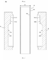
- 2A is a cross-sectional view taken along the line AA in FIG. 1A
- FIG. 2B shows a state after the inner bag 14 has contracted away from the outer shell 12 from the state of FIG. 2A.
- It is sectional drawing for demonstrating the manufacturing method of a container main body 3.
- the state where the mold 31 and the parison 33 in FIG. 3 are viewed from the BB plane is shown (the parison 33 shows only the outer shape by a dotted line for convenience).
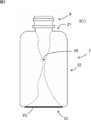
- It is a front view which shows the container main body 3 of the double container 1 of a comparative example.
- the double container 1 includes a container body 3.
- the container body 3 includes a storage portion 7 and a mouth portion 9.
- the container body 3 includes an outer shell 12 and an inner bag 14 in the accommodating portion 7 and the mouth portion 9. As the contents decrease, the inner bag 14 contracts away from the outer shell 12. Before filling the contents, the inner bag 14 may be peeled off from the outer shell 12 and then the inner bag 14 may be filled with the contents. When the contents are discharged from the inner bag 14, the inner bag 14 may be filled. May be peeled off from the outer shell 12.
- the outer shell 12 is formed to be thicker than the inner bag 14 so as to have high resilience.
- the outer shell 12 is composed of, for example, low-density polyethylene, linear low-density polyethylene, high-density polyethylene, polypropylene, polyolefins such as ethylene-propylene copolymers and mixtures thereof, polyesters such as PET, and the like.
- the outer shell 12 may have a plurality of layers.
- the inner bag 14 is preferably composed of a plurality of layers.
- an EVOH layer made of an ethylene-vinyl alcohol copolymer (EVOH) resin can be used for the layer in contact with the outer layer, and for example, the inner surface layer made of the above-mentioned polyolefin or polyester can be used for the layer in contact with the contents. Then, it is preferable to use an adhesive layer between the EVOH layer and the inner surface layer.
- EVOH ethylene-vinyl alcohol copolymer
- the container body 3 can be formed by direct blow molding (blow molding performed using a tubular parison in a molten state), and in this case, the container body 3 is an extrusion head (as shown in FIGS. 3 to 4). It can be formed by blow molding a tubular laminated parison 33 in a molten state extruded from (not shown) using a pair of dies 31 and 32.
- the parison 33 has a layer structure similar to that of the outer shell 12 and the inner bag 14.
- the parison 33 includes an outer layer 33a serving as an outer shell 12 and an inner layer 33b serving as an inner bag 14 in this order from the outer surface side.
- the molds 31 and 32 are provided with cavity surfaces 31a and 32a, and the outer shape of the container body 3 is defined by the shape defined by the cavity surfaces 31a and 32a when the molds 31 and 32 are closed.
- the cavity surfaces 31a and 32a are formed so as to be continuous with the portions 31a1 and 32a1 to be the accommodating portion 7, the portions 31a2 and 32a2 to be the mouth portion 9, and the portions 31a3 to be the bag portion to be cut after molding. , 32a3.
- the mouth portion 9 includes an engaging portion 9d to which a mouth portion mounting member such as a cap or a pump can be mounted.
- the engaging portion 9d is a male screw portion when the mouth mounting member is a screw type, and is an annular protrusion protruding in the circumferential direction when the mouth mounting member is a plug type.
- the mouth portion 9 is provided so as to extend from the upper end of the accommodating portion 7.
- the mouth-mounted member preferably has a check valve so that the contents can be discharged, but the outside air does not flow into the container body 3.
- the mouth portion 9 has a substantially cylindrical shape.
- the accommodating portion 7 has a larger circumscribed circle diameter than the mouth portion 9. All or most of the contents are housed in the housing portion 7, and the contents are discharged to the outside through the mouth portion 9 and the mouth portion mounting member.
- the accommodating portion 7 has a shoulder portion 21, a body portion 22, and a bottom portion 23 in this order from the mouth portion 9 side.
- the body portion 22 is provided between the shoulder portion 21 and the bottom portion 23.
- the shoulder portion 21 is a portion that can be seen when the container body 3 is viewed from the mouth portion 9 side in the direction along the central axis C of the mouth portion 9 (a portion that is visible in FIG. 1A excluding the mouth portion 9). be.
- the bottom portion 23 is a portion (a portion visible in FIG. 1C) that can be seen when the container body 3 is viewed from the opposite side of the mouth portion 9 in the direction along the central axis C of the mouth portion 9.
- the body portion 22 is a portion of the accommodating portion 7 other than the shoulder portion 21 and the bottom portion 23.
- the shoulder portion 21 is provided with a pair of upper holding portions 24a and 24b (the symbols a and b are omitted when distinction is unnecessary) provided so as to sandwich the mouth portion 9.
- the outer shell 12 holds the inner bag 14, and the inner bag 14 cannot be separated from the outer shell 12.
- the inner surfaces of the inner bags 14 are close to each other and the flow path through which the contents pass is narrowed. 25 is likely to be formed, but in the container body 3 in which the upper holding portions 24a and 24b are provided on the shoulder portion 21 as in the present embodiment, as shown in FIGS.
- the upper holding portions 24a and 24b are formed. Since the inner bag 14 is regulated in the above, when the inner bag 14 contracts, it becomes difficult for the inner surfaces of the inner bags 14 to come close to each other in the direction in which the upper holding portion 24 extends (the left-right direction in FIG. 1B). As a result, the narrowed portion 25 is less likely to be formed. Since the contents (particularly, viscous contents such as mayonnaise and ketchup) do not easily pass through the narrowed portion 25, when the narrowed portion 25 is formed, the ejection property of the contents tends to deteriorate. Therefore, in the present embodiment, the deterioration of the ejection property of the contents is suppressed by suppressing the formation of the narrowed portion 25.
- the upper holding portion 24 is preferably a pinch-off portion P1 formed by sandwiching the parison 33 with a pair of dies 31 and 32 in direct blow molding, as shown in FIGS. 3 to 4.
- blow molding is generally performed using a parison whose outer diameter is smaller than the outer diameter of the mouth portion.
- the pinch-off portion is formed only in the portion where the tubular parison is closed on the bottom side and the mouth side of the container, but the pinch-off portion on the mouth side is usually cut off to form an opening. Therefore, as shown in FIG. 5, the pinch-off portion P2 is provided only on the bottom portion 23 of the container body 3, and the shoulder portion 21 is not provided with the pinch-off portion.
- blow molding is performed using a parison 33 having an outer diameter larger than the outer diameter of the mouth portion 9.
- the parison 33 is sandwiched between the molds 31 and 32 at the portion serving as the shoulder portion 21, and the pinch-off portion P1 is formed.
- the pinch-off portion P1 is also formed on the side surface of the mouth portion 9 so as to be continuous from the shoulder portion 21.
- the upper holding portion 24 is provided so as to straddle the shoulder portion 21 and the mouth portion 9.
- the container body 3 is molded using such a parison 33 having a large outer diameter, the degree of stretching (blow ratio) of the parison 33 during molding decreases, so that the degree of uneven thickness of the container body 3 decreases. Benefits are obtained.
- the cross-sectional shape of the body portion 22 is not particularly limited, but at least a part thereof is preferably a flat shape, and it is more preferable that the whole body portion 22 has a flat shape.
- the blow ratio tends to be large, so that the technical significance of applying the present invention is particularly remarkable.
- the flatness is defined by Equation 1.
- the maximum radius R1 and the minimum radius R2 are containers from the central axis C at the positions where the distance from the central axis C is the maximum and the minimum at the height position where the flatness is measured, respectively. The distance to the outer surface.
- Flatness maximum radius R1 / minimum radius R2 in the cross section perpendicular to the central axis C of the mouth portion 9.
- the flatness may be constant or change along the central axis C.
- the maximum flatness (flatness at the site where the flatness is maximum) is, for example, 1.2 to 6, preferably 1.5 to 5. This value is, for example, 1.2, 1.5, 2.0, 2.5, 3.0, 3.5, 4.0, 4.5, 5.0, 5.5, 6.0. Yes, it may be within the range between any two of the numerical values exemplified here.
- D2 / D1 is, for example, 1.1 to 3, for example, 1.1. , 1.2, 1.3, 1.4, 1.5, 1.6, 1.7, 1.8, 1.9, 2.0, 2.5, 3.0, and are exemplified here. It may be within the range between any two of the given numerical values. Further, assuming that the outer diameter of the portion having the maximum outer diameter of the body portion 22 is D3, D2 is preferably smaller than D3.
- D2 is preferably D1 + (D3-D1) ⁇ ⁇ , and ⁇ is preferably 0.1 to 0.9, for example, 0.1, 0.2, 0.3, 0.4, 0. It is 5, 0.6, 0.7, 0.8, 0.9, and may be within the range between any two of the numerical values exemplified here.
- the outer shells 12 on both sides of the upper holding portion 24 are connected to each other, the upper holding portion 24 does not have air permeability, and the upper holding portion 24 does not have air permeability.
- the outside air cannot be introduced between the outer shell 12 and the inner bag 14 through the portion 24.
- the outer shell 12 can more reliably hold the inner bag 14 in the upper holding portion 24.
- the portion where the upper holding portion 24 is provided preferably has an angle of 70 to 90 degrees with respect to the central axis C of the mouth portion 9.
- This angle is, for example, 70, 75, 80, 85, 90 degrees, and may be within the range between any two of the numerical values exemplified here.
- the bottom portion 23 is provided with a pinch-off portion P2 formed by sandwiching the parison 33 with the molds 31 and 32.
- the pinch-off portion P2 is a lower holding portion 34 in which the outer shell 12 holds the inner bag 14.
- the inner bag 14 since the inner bag 14 is restricted in the upper holding portions 24a and 24b and the lower holding portion 34, when the inner bag 14 contracts, the inner bag 14 extends in the direction in which the upper holding portion 24 extends. It becomes difficult for the inner surfaces to come close to each other.
- a gap is formed between the outer shell 12 and the inner bag 14, and the outside air introduction portion for introducing the outside air between the outer shell 12 and the inner bag 14 through this gap.
- the outside air introduction portion can be formed without drilling the outer shell 12.
- the inner bag 14 may not be pinched by the outer shell 12 in the pinch-off portion P2, and in that case, the inner bag 14 is regulated only by the upper pinching portions 24a and 24b.
- the pinch-off portion P2 is used as the lower holding portion 34, it is preferable to drill the outer shell 12 to form an outside air introduction hole at a portion other than the lower holding portion 34 and the upper holding portion 24.
- Double container 3 Container body, 7: Storage part, 9: Mouth part, 9d: Engagement part, 12: Outer shell, 14: Inner bag, 21: Shoulder part, 22: Body part, 23: Bottom part , 24: Upper holding part, 24a: Upper holding part, 24b: Upper holding part, 25: Narrow part, 31: Mold, 31a: Cavity surface, 31a1: Site, 31a2: Site, 31a3: Site, 32: Mold , 32a: Cavity surface, 32a1: Site, 32a2: Site, 32a3: Site, 33: Laminated parison, 33a: Outer layer, 33b: Inner layer, 34: Lower pinching part, C: Central axis, P1: Pinch-off part, P2: Pinch off part
Landscapes
- Engineering & Computer Science (AREA)
- Ceramic Engineering (AREA)
- Mechanical Engineering (AREA)
- Containers Having Bodies Formed In One Piece (AREA)
- Packages (AREA)
Abstract
内袋が収縮する際に内袋に狭窄部が形成されることが抑制される、二重容器を提供する。 本発明によれば、外殻と内袋とを有し且つ内容物の減少に伴って前記内袋が収縮するように構成された容器本体を有する二重容器であって、前記容器本体は、収容部と、口部を備え、前記口部は、前記収容部の上端から延びるように設けられ、前記収容部は、前記口部側から順に、肩部と、胴部と、底部を有し、前記胴部は、前記肩部と前記底部の間に設けられ、前記肩部は、前記口部の中心軸に沿った方向に、前記口部側から前記容器本体を見たときに見える部位であり、前記肩部には、前記口部を挟むように設けられた一対の上側挟持部が設けられ、前記上側挟持部では、前記外殻が前記内袋を挟持する、二重容器が提供される。
Description
本発明は、二重容器に関する。
特許文献1には、外殻と内袋とを有し且つ内容物の減少に伴って内袋が収縮する容器本体を備える二重容器が開示されている。
特許文献1のような容器では、内袋が収縮する際に内袋の対向する内面同士が近接して、内容物が通る流路が狭くなった狭窄部が形成されてしまう場合がある。狭窄部が形成されると、内容物の吐出性が悪くなる場合がある。
本発明はこのような事情に鑑みてなされたものであり、内袋が収縮する際に内袋に狭窄部が形成されることが抑制される、二重容器を提供するものである。
本発明によれば、外殻と内袋とを有し且つ内容物の減少に伴って前記内袋が収縮するように構成された容器本体を有する二重容器であって、前記容器本体は、収容部と、口部を備え、前記口部は、前記収容部の上端から延びるように設けられ、前記収容部は、前記口部側から順に、肩部と、胴部と、底部を有し、前記胴部は、前記肩部と前記底部の間に設けられ、前記肩部は、前記口部の中心軸に沿った方向に、前記口部側から前記容器本体を見たときに見える部位であり、前記肩部には、前記口部を挟むように設けられた一対の上側挟持部が設けられ、前記上側挟持部では、前記外殻が前記内袋を挟持する、二重容器が提供される。
本発明では、肩部に設けられた一対の上側挟持部において内袋が外殻によって挟持されているので、上側挟持部が延在する方向において、内袋の対向する内面同士が近接しにくくなり、狭窄部が形成されることが抑制される。
以下、本発明の種々の実施形態を例示する。以下に示す実施形態は互いに組み合わせ可能である。
好ましくは、前記記載の二重容器であって、前記上側挟持部では、前記外殻と前記内袋の間に隙間が設けられていない、二重容器である。
好ましくは、前記記載の二重容器であって、前記胴部は、少なくとも一部が扁平形状である、二重容器である。
好ましくは、前記記載の二重容器であって、前記上側挟持部では、前記外殻と前記内袋の間に隙間が設けられていない、二重容器である。
好ましくは、前記記載の二重容器であって、前記胴部は、少なくとも一部が扁平形状である、二重容器である。
以下、本発明の実施形態について説明する。以下に示す実施形態中で示した各種特徴事項は、互いに組み合わせ可能である。また、各特徴について独立して発明が成立する。
図1に示すように、本発明の一実施形態の二重容器1は、容器本体3を備える。容器本体3は、収容部7と、口部9を備える。
図1~図2に示すように、容器本体3は、収容部7及び口部9において、外殻12と内袋14を備える。内容物の減少に伴って内袋14が外殻12から離れて収縮する。内容物の充填前に内袋14を外殻12から剥離する予備剥離を行ってから内袋14内に内容物を充填してもよく、内袋14から内容物を吐出する際に内袋14を外殻12から剥離させてもよい。
外殻12は、復元性が高くなるように、内袋14よりも肉厚に形成される。外殻12は、例えば、低密度ポリエチレン、直鎖状低密度ポリエチレン、高密度ポリエチレン、ポリプロピレン、エチレン-プロピレン共重合体及びその混合物などのポリオレフィンやPETなどのポリエステル等で構成される。外殻12は、複数層構成であってもよい。内袋14は、複数の層から構成することが好ましい。例えば、外層と接触する層にエチレン-ビニルアルコール共重合体(EVOH)樹脂からなるEVOH層を用い、内容物に接触する層に、例えば、上記ポリオレフィン又はポリエステルからなる内面層を用いることができる。そして、上記EVOH層と内面層との間には、接着層を用いることが好ましい。
容器本体3は、ダイレクトブロー成形(溶融状態の筒状のパリソンを用いて行うブロー成形)によって形成可能であり、この場合、容器本体3は、図3~図4に示すように、押出ヘッド(不図示)から押し出された溶融状態の筒状の積層パリソン33を一対の金型31,32を用いてブロー成形することによって形成することができる。パリソン33は、外殻12及び内袋14と同様の層構成を有する。一例では、パリソン33は、外面側から順に、外殻12となる外層33aと、内袋14となる内層33bを備える。金型31,32は、キャビティ面31a,32aを備え、金型31,32を閉じたときにキャビティ面31a,32aによって規定される形状によって容器本体3の外形が規定される。キャビティ面31a,32aは、収容部7となる部位31a1,32a1と、口部9となる部位31a2,32a2と、口部9から連なるように形成され且つ成形後に切断される袋部となる部位31a3,32a3を備える。
図1に示すように、口部9は、キャップやポンプなどの口部装着部材を装着可能な係合部9dを備える。係合部9dは、口部装着部材がネジ式の場合は雄ねじ部であり、口部装着部材が打栓式の場合は周方向に突出する環状突起である。口部9は、収容部7の上端から延びるように設けられている。口部装着部材は、好ましくは、逆止弁を有しており、内容物の吐出は可能であるが、外気が容器本体3内に流入しないようになっている。口部9は、略円筒形である。収容部7は、口部9よりも外接円径が大きい。内容物の全部又は大部分が収容部7内に収容され、内容物は口部9及び口部装着部材を通じて外部に吐出される。
収容部7は、口部9側から順に、肩部21と、胴部22と、底部23を有する。胴部22は、肩部21と底部23の間に設けられる。肩部21は、口部9の中心軸Cに沿った方向に、口部9側から容器本体3を見たときに見える部位(図1Aで見える部位から口部9を除いた部位))である。底部23は、口部9の中心軸Cに沿った方向に、口部9の反対側から容器本体3を見たときに見える部位(図1Cで見える部位)である。胴部22は、収容部7のうち、肩部21及び底部23以外の部位である。
肩部21には、口部9を挟むように設けられた一対の上側挟持部24a,24b(区別が不要なときは符号のa,bは省略する。)が設けられている。図2に示すように、上側挟持部24では、外殻12が内袋14を挟持しており、内袋14が外殻12から離れることができない。肩部21に上側挟持部24が設けられていない比較例の容器本体では、図5に示すように、内袋14の内面同士が近接して、内容物が通る流路が狭くなった狭窄部25が形成されやすいが、本実施形態にように、肩部21に上側挟持部24a,24bが設けられている容器本体3では、図1~図2に示すように、上側挟持部24a,24bにおいて内袋14が規制されているので、内袋14が収縮する際に、上側挟持部24が延在する方向(図1Bの左右方向)において内袋14の内面同士が近接しにくくなり、その結果、狭窄部25が形成されにくくなる。内容物(特に、マヨネーズやケチャップのような粘稠性内容物)は狭窄部25を通過しにくいので、狭窄部25が形成されると、内容物の吐出性が悪くなりやすい。このため、本実施形態では、狭窄部25の形成を抑制することによって、内容物の吐出性の悪化を抑制している。
上側挟持部24は、好ましくは、図3~図4に示すように、ダイレクトブロー成形において一対の金型31,32でパリソン33を挟んで形成されるピンチオフ部P1である。一般に、ダイレクトブロー成形では、口部の外径よりも、外径が小さいパリソンを用いてブロー成形を行うのが一般的である。この場合、筒状パリソンが容器の底部側と口部側で閉じられた部位にのみピンチオフ部が形成されるが、口部側のピンチオフ部は通常は切除されて開口部が形成される。このため、図5に示すように、容器本体3の底部23にのみピンチオフ部P2が設けられ、肩部21にはピンチオフ部が設けられない。一方、本実施形態では、肩部21にピンチオフ部P1を形成して上側挟持部24として活用すべく、口部9の外径よりも外径が大きいパリソン33を用いてブロー成形を行うことによって、肩部21となる部位においてパリソン33を金型31,32で挟んでピンチオフ部P1を形成している。また、肩部21にピンチオフ部P1が形成される場合、口部9の側面にも肩部21から連なるようにピンチオフ部P1が形成される。この場合、上側挟持部24は、肩部21と口部9にまたがるように設けられる。また、このような外径が大きいパリソン33を用いて容器本体3を成形すると、成形時にパリソン33が引き伸ばされる度合い(ブロー比)が低下するので、容器本体3の偏肉の度合いが小さくなるという利点が得られる。
ところで、胴部22の断面形状は、特に限定されないが、少なくとも一部が扁平形状であることが好ましく、全体が扁平形状であることがさらに好ましい。胴部22が扁平形状である場合、ブロー比が大きくなりやすいので、本発明を適用する技術的意義が特に顕著である。ここで、扁平度を式1によって定義する。最大半径R1及び最小半径R2は、それぞれ、図1Aに示すように、扁平度を測定する高さ位置での、中心軸Cからの距離が最大及び最小となる部位での、中心軸Cから容器外面までの距離である。
(式1)扁平度=口部9の中心軸Cに垂直な断面での最大半径R1/最小半径R2
(式1)扁平度=口部9の中心軸Cに垂直な断面での最大半径R1/最小半径R2
扁平度は、中心軸Cに沿って一定であっても変化してもよい。最大扁平度(扁平度が最大となる部位での扁平度)は、例えば、1.2~6であり、1.5~5が好ましい。この値は、例えば、1.2、1.5、2.0、2.5、3.0、3.5、4.0、4.5、5.0、5.5、6.0であり、ここで例示した数値の何れか2つの間の範囲内であってもよい。
図1及び図3に示すように、口部9の外径をD1とし、パリソン33の外径をD2とすると、D2/D1は、例えば、1.1~3であり、例えば、1.1、1.2、1.3、1.4、1.5、1.6、1.7、1.8、1.9、2.0、2.5、3.0であり、ここで例示した数値の何れか2つの間の範囲内であってもよい。また、胴部22の外径が最大の部位の外径をD3とすると、D2は、D3よりも小さいことが好ましい。D2は、好ましくは、D1+(D3-D1)×αであり、αは、0.1~0.9が好ましく、例えば、0.1、0.2、0.3、0.4、0.5、0.6、0.7、0.8、0.9であり、ここで例示した数値の何れか2つの間の範囲内であってもよい。
ところで、ピンチオフ部では、外殻12の溶着強度が比較的低いので、ピンチオフ部に衝撃を加えることによって外殻12と内袋14の間に隙間を形成して、この隙間を、外殻12と内袋14の間に外気を導入するための外気導入部と利用することが考えられる。しかし、上側挟持部24において外殻12と内袋14の間に隙間を形成すると、上側挟持部24において内袋14が外殻12によって挟持されなくなる場合がある。この場合、狭窄部25の形成が抑制されなくなる。このため、本実施形態では、外殻12と内袋14の間に隙間が設けられていない。言い換えると、上側挟持部24では、図2Aに示すように、上側挟持部24を挟んだ両側の外殻12同士がつながっており、上側挟持部24が通気性を有しておらず、上側挟持部24を通じて外殻12と内袋14の間に外気を導入することができないようになっている。これによって、上側挟持部24において外殻12が内袋14をより確実に保持可能になっている。
肩部21のうち、上側挟持部24が設けられている部位は、口部9の中心軸Cに対する角度が70~90度であることが好ましい。この角度は、例えば、70、75、80、85、90度であり、ここで例示した数値の何れか2つの間の範囲内であってもよい。このように中心軸Cに対してほぼ垂直となる部位に上側挟持部24を設けることによって、上側挟持部24が延在する方向において内袋14の内面同士が近接することがより効果的に抑制される。
底部23には、上述したように、金型31,32でパリソン33を挟んで形成されるピンチオフ部P2が設けられる。成形直後の状態では、ピンチオフ部P2は、外殻12が内袋14を挟持する下側挟持部34となっている。この状態では、上側挟持部24a,24b及び下側挟持部34において内袋14が規制されているので、内袋14が収縮する際に、上側挟持部24が延在する方向において内袋14の内面同士がより近接しにくくなる。
一方、ピンチオフ部P2に衝撃を加えることによって外殻12と内袋14の間に隙間を形成して、この隙間を、外殻12と内袋14の間に外気を導入するための外気導入部として利用してもよい。この場合、外殻12を穿孔することなく、外気導入部を形成することができる。なお、この場合、ピンチオフ部P2において内袋14が外殻12によって挟持されなくなる場合があり、その場合は、内袋14は、上側挟持部24a,24bのみによって規制される。ピンチオフ部P2を下側挟持部34として活用する場合には、下側挟持部34及び上側挟持部24以外の部位において、外殻12を穿孔して外気導入孔を形成することが好ましい。
1:二重容器、3:容器本体、7:収容部、9:口部、9d:係合部、12:外殻、14:内袋、21:肩部、22:胴部、23:底部、24:上側挟持部、24a:上側挟持部、24b:上側挟持部、25:狭窄部、31:金型、31a:キャビティ面、31a1:部位、31a2:部位、31a3:部位、32:金型、32a:キャビティ面、32a1:部位、32a2:部位、32a3:部位、33:積層パリソン、33a:外層、33b:内層、34:下側挟持部、C:中心軸、P1:ピンチオフ部、P2:ピンチオフ部
Claims (3)
- 外殻と内袋とを有し且つ内容物の減少に伴って前記内袋が収縮するように構成された容器本体を有する二重容器であって、
前記容器本体は、収容部と、口部を備え、
前記口部は、前記収容部の上端から延びるように設けられ、
前記収容部は、前記口部側から順に、肩部と、胴部と、底部を有し、
前記胴部は、前記肩部と前記底部の間に設けられ、
前記肩部は、前記口部の中心軸に沿った方向に、前記口部側から前記容器本体を見たときに見える部位であり、
前記肩部には、前記口部を挟むように設けられた一対の上側挟持部が設けられ、
前記上側挟持部では、前記外殻が前記内袋を挟持する、二重容器。 - 請求項1に記載の二重容器であって、
前記上側挟持部では、前記外殻と前記内袋の間に隙間が設けられていない、二重容器。 - 請求項1又は請求項2に記載の二重容器であって、
前記胴部は、少なくとも一部が扁平形状である、二重容器。
Priority Applications (1)
| Application Number | Priority Date | Filing Date | Title |
|---|---|---|---|
| CN202180069042.9A CN116323406A (zh) | 2020-10-29 | 2021-10-25 | 双重容器 |
Applications Claiming Priority (2)
| Application Number | Priority Date | Filing Date | Title |
|---|---|---|---|
| JP2020181810A JP7549205B2 (ja) | 2020-10-29 | 2020-10-29 | 二重容器 |
| JP2020-181810 | 2020-10-29 |
Publications (1)
| Publication Number | Publication Date |
|---|---|
| WO2022091997A1 true WO2022091997A1 (ja) | 2022-05-05 |
Family
ID=81381458
Family Applications (1)
| Application Number | Title | Priority Date | Filing Date |
|---|---|---|---|
| PCT/JP2021/039222 Ceased WO2022091997A1 (ja) | 2020-10-29 | 2021-10-25 | 二重容器 |
Country Status (3)
| Country | Link |
|---|---|
| JP (1) | JP7549205B2 (ja) |
| CN (1) | CN116323406A (ja) |
| WO (1) | WO2022091997A1 (ja) |
Citations (2)
| Publication number | Priority date | Publication date | Assignee | Title |
|---|---|---|---|---|
| JPH09286117A (ja) * | 1996-02-23 | 1997-11-04 | Canon Inc | 液体収納容器、該容器の製造方法、該容器を用いるインクジェットカートリッジ及びインクジェット記録装置 |
| JPH10151762A (ja) * | 1996-08-02 | 1998-06-09 | Canon Inc | 負圧を与える液体収納容器、該容器とインクジェット記録ヘッドとを一体化したインクジェットカートリッジ及び該容器の製造方法 |
Family Cites Families (5)
| Publication number | Priority date | Publication date | Assignee | Title |
|---|---|---|---|---|
| JP5288175B2 (ja) * | 2008-11-28 | 2013-09-11 | 株式会社吉野工業所 | 合成樹脂製二重容器 |
| JP2015048091A (ja) * | 2013-08-30 | 2015-03-16 | 勉 横山 | 容器用キャップ、及び該キャップを有する容器 |
| KR101995407B1 (ko) * | 2014-12-19 | 2019-07-02 | 교라꾸 가부시끼가이샤 | 적층박리용기 및 적층박리용기로의 캡의 장착 방법 |
| JP6959498B2 (ja) * | 2017-01-26 | 2021-11-02 | キョーラク株式会社 | 積層剥離容器 |
| JP7260258B2 (ja) * | 2018-06-13 | 2023-04-18 | 株式会社 資生堂 | 蓋つき容器、多重容器、及び蓋つき容器の組み立て方法 |
-
2020
- 2020-10-29 JP JP2020181810A patent/JP7549205B2/ja active Active
-
2021
- 2021-10-25 WO PCT/JP2021/039222 patent/WO2022091997A1/ja not_active Ceased
- 2021-10-25 CN CN202180069042.9A patent/CN116323406A/zh active Pending
Patent Citations (2)
| Publication number | Priority date | Publication date | Assignee | Title |
|---|---|---|---|---|
| JPH09286117A (ja) * | 1996-02-23 | 1997-11-04 | Canon Inc | 液体収納容器、該容器の製造方法、該容器を用いるインクジェットカートリッジ及びインクジェット記録装置 |
| JPH10151762A (ja) * | 1996-08-02 | 1998-06-09 | Canon Inc | 負圧を与える液体収納容器、該容器とインクジェット記録ヘッドとを一体化したインクジェットカートリッジ及び該容器の製造方法 |
Also Published As
| Publication number | Publication date |
|---|---|
| JP2022072403A (ja) | 2022-05-17 |
| JP7549205B2 (ja) | 2024-09-11 |
| CN116323406A (zh) | 2023-06-23 |
Similar Documents
| Publication | Publication Date | Title |
|---|---|---|
| JP6959498B2 (ja) | 積層剥離容器 | |
| JP6529187B2 (ja) | 袋体用注出具、注出具付袋体、及び、袋体用注出具の製造方法 | |
| KR100708830B1 (ko) | 블로 성형품 | |
| JP6494984B2 (ja) | 二軸延伸ブロー成形用のプリフォーム及び容器 | |
| EP1459996A1 (en) | Fill-out container | |
| US7051893B2 (en) | Liquid container, liquid container manufacturing method, and metallic mold for liquid container manufacturing method | |
| JP2021127164A (ja) | 二重容器 | |
| WO2004039560A1 (ja) | ブロー成形容器及びブロー成形用金型 | |
| WO2022091997A1 (ja) | 二重容器 | |
| KR102227322B1 (ko) | 이중 용기 및 그 제조 방법 | |
| JPH033460Y2 (ja) | ||
| JP7308050B2 (ja) | 二重容器の評価方法 | |
| JP2024049988A (ja) | 二重容器、容器本体の製造方法、及びプリフォームの製造方法 | |
| JP7295393B2 (ja) | 積層剥離容器 | |
| JP2021070489A (ja) | 二重容器 | |
| JP2016179854A (ja) | 包装体 | |
| JPH0144576B2 (ja) | ||
| JP7663813B2 (ja) | 二重容器及びその処理方法 | |
| JP7657596B2 (ja) | スパウトおよびスパウト付きパウチ容器 | |
| JPH0141579Y2 (ja) | ||
| JP7352064B2 (ja) | 二重容器 | |
| JP7175751B2 (ja) | ブロー成形容器 | |
| JP2024129325A (ja) | 紙製チューブ容器及びその製造方法 | |
| JP2025184196A (ja) | プリフォーム及びその製造方法、容器の製造方法 | |
| JPS60204465A (ja) | 押し出し容器及びその製造方法 |
Legal Events
| Date | Code | Title | Description |
|---|---|---|---|
| 121 | Ep: the epo has been informed by wipo that ep was designated in this application |
Ref document number: 21886115 Country of ref document: EP Kind code of ref document: A1 |
|
| NENP | Non-entry into the national phase |
Ref country code: DE |
|
| 122 | Ep: pct application non-entry in european phase |
Ref document number: 21886115 Country of ref document: EP Kind code of ref document: A1 |