WO2022091784A1 - カテーテル - Google Patents
カテーテル Download PDFInfo
- Publication number
- WO2022091784A1 WO2022091784A1 PCT/JP2021/037876 JP2021037876W WO2022091784A1 WO 2022091784 A1 WO2022091784 A1 WO 2022091784A1 JP 2021037876 W JP2021037876 W JP 2021037876W WO 2022091784 A1 WO2022091784 A1 WO 2022091784A1
- Authority
- WO
- WIPO (PCT)
- Prior art keywords
- catheter
- rigidity
- strands
- wire
- low
- Prior art date
- Legal status (The legal status is an assumption and is not a legal conclusion. Google has not performed a legal analysis and makes no representation as to the accuracy of the status listed.)
- Ceased
Links
Images


Classifications
-
- A—HUMAN NECESSITIES
- A61—MEDICAL OR VETERINARY SCIENCE; HYGIENE
- A61B—DIAGNOSIS; SURGERY; IDENTIFICATION
- A61B17/00—Surgical instruments, devices or methods
- A61B17/22—Implements for squeezing-off ulcers or the like on inner organs of the body; Implements for scraping-out cavities of body organs, e.g. bones; for invasive removal or destruction of calculus using mechanical vibrations; for removing obstructions in blood vessels, not otherwise provided for
-
- A—HUMAN NECESSITIES
- A61—MEDICAL OR VETERINARY SCIENCE; HYGIENE
- A61M—DEVICES FOR INTRODUCING MEDIA INTO, OR ONTO, THE BODY; DEVICES FOR TRANSDUCING BODY MEDIA OR FOR TAKING MEDIA FROM THE BODY; DEVICES FOR PRODUCING OR ENDING SLEEP OR STUPOR
- A61M25/00—Catheters; Hollow probes
Definitions
- the techniques disclosed herein relate to catheters with dilators.
- the catheter comprises a hollow shaft and an extension connected to the tip of the shaft.
- the extended body is a tubular body formed so as to be expandable and contractible in the radial direction by a plurality of strands.
- Some catheters with dilators are used as follows. If the lesion is very hard, such as chronic total occlusion (CTO) or calcification stenosis, the guide wire inserted from one side may not be able to penetrate the lesion. In this case, the tip of the catheter is guided to the lesion in a state where the dilator is contracted, and the dilator is inserted and expanded in the space formed halfway of the lesion. Next, the retro guide wire is inserted into the lesion from the side opposite to the guide wire. The tip of the inserted retro guide wire enters the dilated body through the gap of the dilated body and then into the shaft, resulting in the formation of a through hole in the lesion. As a result, treatment of the lesion can be advanced.
- CTO chronic total occlusion
- calcification stenosis the guide wire inserted from one side may not be able to penetrate the lesion.
- the tip of the catheter is guided to the lesion in a state where the
- the rigidity of all the wires constituting the dilated body is the same as each other.
- the rigidity of the plurality of strands constituting the dilated body is relatively low, the dilating force for expanding the blood vessel or the lesion portion by changing the dilated body from the contracted state to the dilated state becomes weak.
- the rigidity of the plurality of strands constituting the dilated body is relatively high, the dilated body is deformed into a shape different from the shape of the wall surface such as a blood vessel when the dilated body is in the expanded state, and the dilated body is a blood vessel.
- the performance (space occupancy) that occupies the space in the same area becomes low.
- the space occupancy is low, the gap between the outer periphery of the dilated body and the wall surface such as a blood vessel becomes wide, and as a result, for example, blood easily flows into the same gap, and the suction force of the dilated body decreases.
- the tip of the retro guide wire easily gets into the same gap and cannot smoothly enter the dilated body.
- This specification discloses a technique capable of solving at least a part of the above-mentioned problems.
- the catheter disclosed in the present specification is a catheter, which is formed by a hollow shaft and a plurality of strands connected to the tip of the shaft so as to be expandable and contractible in the radial direction of the catheter.
- the plurality of strands constituting the extended body include a cylindrical extended body, and the expanded body has a high-rigidity wire having a relatively high radial bending rigidity and the bending rigidity of the expanded body. Includes low-rigidity strands that are lower than high-rigidity strands.
- the expandability to dilate a blood vessel or a lesion is high as compared with a configuration in which the rigidity of all the strands constituting the dilator is relatively low.
- the rigidity of all the strands constituting the dilated body is relatively high, it is deformed according to the shape of the wall surface of the blood vessel or the like, and the gap between the outer periphery of the dilated body and the wall surface of the blood vessel or the like is formed. Since it becomes narrower, the space occupancy of the dilated body occupying the space in the blood vessel or the like is increased. That is, according to this catheter, it is possible to achieve both the expandability of the dilator and the space occupancy.
- the plurality of strands may be arranged spirally with a gap between them.
- both dilatability and space occupancy of the dilator can be achieved at the same time.
- the plurality of strands may be arranged so as to intersect each other in a mesh pattern.
- both dilatability and space occupancy of the dilator can be achieved at the same time.
- the low-rigidity wire may have a flat shape in which the width in the radial direction is smaller than the width in the circumferential direction of the dilator. According to this catheter, the low-rigidity wire having a relatively low rigidity is more likely to be displaced in the circumferential direction than the configuration in which the radial width of the low-rigidity wire is equal to or larger than the circumferential width. Since the gap between the outer periphery of the dilated body and the wall surface of the blood vessel or the like is narrowed, the space occupancy of the dilated body can be improved more effectively.
- the plurality of strands include the plurality of the high-rigidity strands and the plurality of the low-rigidity strands, and the plurality of strands are viewed from the axial direction of the dilator.
- the high-rigidity strands may be arranged at positions symmetrical with respect to the axis, and the plurality of low-rigidity strands may be arranged at positions symmetrical with respect to the axis. According to this catheter, it is possible to suppress the bias of the shape of the dilated body as compared with the configuration in which at least one of the high-rigidity wire and the low-rigidity wire is asymmetrically arranged.
- the area of the cross section perpendicular to the length direction of the high-rigidity wire may be larger than the area of the cross section perpendicular to the length direction of the low-rigidity wire.
- the difference in the area of the cross section perpendicular to the length direction makes it possible to effectively lower the flexural rigidity of the extension body of the low-rigidity wire in the radial direction than the bending rigidity of the high-rigidity wire.
- the outer shape of the cross section perpendicular to the length direction of the high-rigidity wire and the outer shape of the cross section perpendicular to the length direction of the low-rigidity wire are different from each other. According to this catheter, a high-rigidity wire and a low-rigidity wire can have different bending characteristics depending on the difference in outer shape.
- the plurality of low-rigidity strands may be configured to include a stranded wire obtained by twisting a plurality of wires. According to this catheter, the flexibility of the low-rigidity wire can be improved as compared with the configuration in which the low-rigidity wire is a single wire.
- the outer diameter of the tip of the dilator may be larger than the outer diameter of the proximal end of the dilator. According to this catheter, the recovered material can be easily recovered in the dilated body.
- the dilator may be formed so as to be self-expandable in the radial direction by elastic deformation of the plurality of strands. According to this catheter, the dilated body can be changed from the contracted state to the dilated state by a relatively simple configuration.
- the outer diameter of the tip of the dilator may be larger than the outer diameter of the shaft. According to this catheter, the recovered material can be easily recovered in the dilated body.
- At least one of the inner peripheral surface and the outer peripheral surface of the dilator may be covered with a thin film.
- the recovered material for example, a thrombus fragment, a retro guide wire, etc.
- the catheter may be further provided with a liquid draining device connected to the proximal end side of the shaft. According to this catheter, in a catheter provided with a liquid draining device, it is possible to achieve both expandability and space occupancy of the dilator.
- the liquid draining device may be configured to be a syringe or a liquid feeding pump. According to this catheter, in a catheter provided with a syringe or a liquid feeding pump, it is possible to achieve both expandability and space occupancy of the dilator.
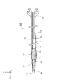
- FIG. 1 is an explanatory diagram schematically showing a vertical cross-sectional configuration of the catheter 100 in the first embodiment.
- the lateral configuration of the dilator 20 described later in the catheter 100 is shown.
- the vertical cross section of the catheter 100 means a cross section (YZ cross section in FIG. 1) parallel to the axial direction (longitudinal direction Z-axis direction in FIG. 1) of the catheter 100.
- the Z-axis negative direction side (the side of the connector 30 described later) is the proximal end side (proximal side) operated by a technician such as a doctor, and the Z-axis positive direction side (opposite to the connector 30).
- the side) is the distal side that is inserted into the body.
- FIG. 1 shows a state in which the catheter 100 is in a straight line parallel to the Z-axis direction as a whole, but the catheter 100 has sufficient flexibility to be curved.
- the catheter 100 is a medical device inserted into a blood vessel or the like for treating or inspecting a lesion L in the blood vessel or the like.
- the catheter 100 includes a dilator 20 at the tip thereof, and is a retro guide wire inserted into the lesion L from the side opposite to the catheter 100 in order to form a through hole in the lesion L.
- the tip is made to enter the expansion body 20 and captured.
- the catheter 100 includes a hollow shaft 10, a tubular expansion body 20 attached to the tip of the shaft 10, and a connector 30 attached to the base of the shaft 10. ..
- the shaft 10 is a cylindrical (for example, cylindrical) hollow body in which the tip and the base end are open.
- the "cylindrical shape" include a cylindrical shape and a square tubular shape, and a taper or unevenness may be formed in a part thereof in the axial direction.
- a lumen S extending from the tip end to the base end of the shaft 10 is formed inside the shaft 10.
- a fluid such as physiological saline to be injected into an abnormal blood vessel is supplied to the lumen S, or a guide wire (not shown) is inserted through the lumen S.
- a port 12 is formed through the side wall of the shaft 10.
- a resin such as polyamide, polyamide elastoma, polyolefin, polyester, polyester elastoma, or a superelastic alloy such as stainless steel (SUS304) or Ni—Ti alloy is used.
- the expansion body 20 is arranged substantially coaxially with the shaft 10.
- the base end of the extension body 20 is connected to the tip end of the shaft 10.
- the expansion body 20 is a braided body (mesh body) formed into a cylindrical shape by braiding a plurality of expansion strands.
- the expansion body 20 has expansion strands 21 and 22.
- the expansion strands 21 and 22 are examples of a plurality of strands within the scope of the claims.
- the expansion strands 21 and 22 are spirally arranged around the central axis of the catheter 100.
- the winding directions of the expansion strands 21 and 22 are opposite to each other and are arranged so as to intersect each other. With such a configuration, the expansion body 20 is formed so as to be able to expand and contract in the radial direction.
- the material for forming the expansion strands 21 and 22 include superelastic alloys such as stainless steel (SUS302, 304,316) and Ni—Ti alloys, or materials having radiation impermeable properties (for example, tungsten and Co—).
- Metals such as Cr alloy
- resins such as polyethylene, polyurethane, polyurethane elastoma, polyamide, polyamide elastoma, polyolefin, polyester and polyester elastoma are used.
- the expansion strands 21 and 22 are single wires.
- the tip tip 40 is joined to the tip of the extension body 20.
- the tip tip 40 has a tubular shape, and the shape of the tip portion of the tip tip 40 is a tapered shape in which the outer diameter decreases toward the tip.
- the insertion hole 42 formed in the tip tip 40 communicates with the space on the inner peripheral side of the expansion body 20.
- a flexible resin such as polyurethane or polyurethane elastomer is used.
- the tip of the core wire 50 is joined to the base end of the tip tip 40.
- the core wire 50 is a linear member, and is inserted into a space on the inner peripheral side of the expansion body 20 and a lumen S of the shaft 10.
- the core wire 50 is, for example, a tapered metal wire having a circular cross section and a smaller outer diameter toward the tip.
- a thin and flexible guide film 60 is formed on the proximal end side portion of the extended body 20.
- the induction film 60 is an example of a thin film within the scope of claims.
- the inductive film 60 is formed in a cylindrical shape so as to cover the inner peripheral side and the outer peripheral side of the proximal end side portion of the extended body 20 over the entire circumference. Specifically, the entire proximal end side portion (expansion strand) of the expansion body 20 is embedded in the induction film 60.
- the tip 62 of the guide film 60 extends axially to the vicinity of the center of the expansion body 20, and the proximal end 64 of the guide film 60 extends to the tip of the shaft 10.
- resins such as polyethylene, polyurethane, polyurethane elastoma, polyamide, polyamide elastoma, polyolefin, polyester, and polyester elastoma are used.
- FIG. 2 is a schematic view of the cross-sectional structure of the extended body 20.
- the cross section of the extended body 20 means a cross section (XY cross section in FIG. 1) perpendicular to the axial direction (Z axis direction in FIG. 1) of the catheter 100.
- FIG. 2 (a) shows the expanded state of the dilated body 20 before being inserted into the lesion portion L
- FIGS. 2 (b) and 2 (c) show the balloon dilated cavity L1 described later in the lesion portion L.
- the expanded state of the expanded body 20 in the state of being inserted into is shown.
- the eight expansion wires 21 and 22 constituting the expansion body 20 include a high-rigidity wire 33 having a relatively high rigidity and a low-rigidity wire 34 having a relatively low rigidity.
- the high-rigidity wire 33 and the low-rigidity wire 34 have substantially the same cross-sectional shape and cross-sectional area.
- the high-rigidity wire 33 is formed of a material having a higher Young's modulus than the low-rigidity wire 34, such as a metal such as tungsten or stainless steel.
- the low-rigidity strand 34 is formed of a metal such as stainless steel or Ni—Ti alloy, or a resin such as polyester or polyester elastoma.
- the materials of the high-rigidity wire 33 and the low-rigidity wire 34 are exemplified, but if the material is selected so as to cause a difference in rigidity between the high-rigidity wire 33 and the low-rigidity wire 34, the high-rigidity wire 33 and the material are selected.
- the material of the low-rigidity wire 34 is not limited.
- the plurality of high-rigidity strands 33 are arranged at positions symmetrical with respect to the coaxial when viewed from the axial direction of the catheter 100, and the plurality of low-rigidity strands 34 are coaxial. It is arranged symmetrically with respect to the relative.
- the strands having the same rigidity may be arranged so as to intersect each other, or the strands having the same rigidity may be arranged in parallel without intersecting each other.
- all the expansion strands 21 may be the high-rigidity strands 33
- all the expansion strands 22 may be the low-rigidity strands 34
- the expansion strands 21 and 22 may be any of them.
- the high-rigidity wire 33 and the low-rigidity wire 34 may be included. When the strands having different rigidity intersect with each other, the intersecting portions of the strands may not be joined and may be movable independently of each other.
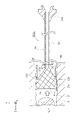
- FIG. 3 is an explanatory view showing a vertical cross-sectional configuration of the catheter 100 in which the dilated body 20 is in the dilated state. In FIG. 3, the lateral configuration of the dilator 20 of the catheter 100 is shown.
- the lesion L formed in the blood vessel B is partially very hard, such as chronic complete occlusion or calcification stenosis, one side (Z-axis negative side in FIG. 3 or less), A guide wire (not shown) inserted from (referred to as "ante side") may not be able to penetrate the lesion L.
- the hole formed on the ante side of the lesion portion L is the other side of the lesion portion L (the Z-axis positive direction side in FIG. 3).
- it does not penetrate to the "retro side” and remains at a position in the middle of the lesion L.
- a balloon catheter (not shown) is guided from the ante side to the lesion L via a guide wire inserted halfway through the lesion L. Then, the contracted balloon in the balloon catheter is inserted into the hole formed in the lesion L to expand the balloon. As a result, the balloon dilated cavity L1 is formed on the ante side of the lesion L.
- the balloon catheter is withdrawn from the balloon dilatation cavity L1 of the lesion L, and instead, the contracted dilated body 20 (see FIG. 1) in the catheter 100 is inserted, and the dilated body 20 is inserted as shown in FIG. Expand.
- the dilated body 20 is held in the balloon dilated cavity L1.
- the retro guide wire 80 is inserted from, for example, the left coronary artery, and is inserted from the retro side of the lesion L via the collateral channel (collateral channel) formed so as to connect the left coronary artery to the right coronary artery.
- the tip of the retro guide wire 80 can reach the balloon dilation cavity L1 through a relatively soft portion on the retro side of the lesion L.
- the positions where the tip of the retro guide wire 80 enters in the balloon dilation cavity L1 are various and difficult to predict.
- the dilated body 20 in the expanded state is inserted in the balloon dilated cavity L1. Therefore, the tip of the retro guide wire 80 is inserted into any one of the plurality of gaps (mesh) formed in the expansion body 20 (for example, P in FIG. 3) and captured.
- the tip of the retro guide wire 80 inserted into the expansion body 20 is guided into the expansion body 20 by the induction film 60. As a result, a through hole is formed in the lesion L. After that, for example, a balloon catheter can be inserted from the retro side of the lesion L to expand the lesion L, and the like can be advanced.
- the plurality of expansion strands 21 and 22 constituting the expansion body 20 include the high-rigidity strands 33 and the low-rigidity strands 34. Therefore, for example, the expandability of expanding the balloon expansion cavity L1 is higher than that of the configuration in which the rigidity of all the expansion strands 21 and 22 constituting the expansion body 20 is relatively low. Further, compared to the configuration in which the rigidity of all the expansion strands 21 and 22 constituting the expansion body 20 is relatively high, the expansion body 20 is deformed according to the shape of the wall surface of the balloon expansion cavity L1, and the expansion body 20 is formed in the lesion portion L. The space occupancy that occupies the inner space is high.
- a force for expanding the balloon dilated cavity L1 is applied by the high-rigidity strand 33 in the balloon dilated cavity L1.
- the low-rigidity wire 34 is deformed according to the distorted wall surface shape of the lesion portion L, so that the formation of a gap between the outer periphery of the extended body 20 and the wall surface of the lesion portion L is suppressed.
- the tip of the retro guide wire 80 can smoothly enter the expansion body 20 without getting lost in the gap. That is, according to the present embodiment, it is possible to achieve both the expandability and the space occupancy of the expansion body 20.
- the expansion strands 21 and 22 are arranged in a mesh pattern so as to intersect each other (see FIGS. 1 and 2). According to the present embodiment, in the catheter 100 provided with such a network-like dilator 20, both the expandability and the space occupancy of the dilator 20 can be achieved at the same time.
- the plurality of high-rigidity strands 33 are arranged at positions symmetrical with respect to the coaxial when viewed from the axial direction of the catheter 100, and the plurality of low-rigidity strands 34 are arranged with respect to the coaxial. (See FIG. 2A). Therefore, the bias of the shape of the expansion body 20 can be suppressed as compared with the configuration in which at least one of the high-rigidity wire 33 and the low-rigidity wire 34 is asymmetrically arranged, and as a result, the retro guide wire 80 The tip portion can be smoothly entered into the expansion body 20.
- the inner peripheral side of the proximal end side portion of the extended body 20 is covered with the guide film 60 over the entire circumference.
- the tip of the retro guide wire 80 inserted in the expansion body 20 can be guided into the expansion body 20 by the guide film 60.
- FIG. 4 is a schematic view of the cross-sectional configuration of the extended body 20a of the catheter 100a in the second embodiment.
- FIG. 4 only the cross-sectional configurations of the eight high-rigidity strands 33 and the low-rigidity strands 34a constituting the expansion body 20 are shown in an enlarged manner.
- the same configurations as those of the catheter 100 of the first embodiment described above are designated by the same reference numerals, and the description thereof will be omitted.
- the low-rigidity wire 34a is a flat shape in which the radial width of the expansion body 20a (catheter 100a) is smaller than the circumferential width of the expansion body 20a. Therefore, the low-rigidity wire 34a, which has a relatively low rigidity, is more likely to be displaced in the radial direction than the configuration in which the radial width of the low-rigidity wire 34a is equal to or larger than the circumferential width. Since the gap between the outer periphery of the expansion body 20a and the wall surface of the balloon expansion cavity L1 is narrowed, the space occupancy of the expansion body 20a can be improved more effectively.
- the low-rigidity wire 34a is difficult to be displaced in the circumferential direction of the expansion body 20a, the low-rigidity wire 34a is displaced in the circumferential direction and another wire (high-rigidity wire 33, low-rigidity wire 34a). It is possible to suppress the deterioration of the insertability of the retro guide wire 80 due to the narrowing of the gap between the two.
- cross section The area of the cross section perpendicular to the length direction of each high-rigidity wire 33 (hereinafter referred to as “cross section”) is larger than the area of the cross section of each low-rigidity wire 34a.
- cross section The area of the cross section perpendicular to the length direction of each high-rigidity wire 33 (hereinafter referred to as “cross section”) is larger than the area of the cross section of each low-rigidity wire 34a.
- the outer shape of the cross section perpendicular to the length direction of each high-rigidity wire 33 and the outer shape of the cross section perpendicular to the length direction of each low-rigidity wire 34a are different from each other.
- the outer shape of each high-rigidity wire 33 is substantially circular
- the outer shape of each low-rigidity wire 34a is substantially rectangular.
- the high-rigidity wire 33 and the low-rigidity wire 34a can have different bending characteristics depending on the difference in outer shape.
- the high-rigidity wire 33 has a bending characteristic in which the degree of freedom of displacement in the circumferential direction of the expansion body 20a is equivalent to the degree of freedom of displacement in the radial direction.
- the low-rigidity wire 34a has a bending characteristic in which the degree of freedom of displacement in the circumferential direction of the extended body 20a is lower than the degree of freedom of displacement in the radial direction.
- the ratio of the radial width to the circumferential width of the low-rigidity wire 34a is lower than the ratio of the radial width to the circumferential width of the high-rigidity wire 33. That is, the low-rigidity wire 34a has higher radial flatness than the high-rigidity wire 33. Therefore, the radial bending rigidity of the low-rigidity wire 34a is lower than the radial bending rigidity of the high-rigidity wire 33.
- the material for forming the high-rigidity wire 33 and the low-rigidity wire 34a is the same.
- the radial width of the low-rigidity wire 34a is smaller than the radial width of the high-rigidity wire 33, and the circumferential width of the low-rigidity wire 34a is the circumferential width of the high-rigidity wire 33. It is almost the same. As a result, it is possible to prevent the gap between the high-rigidity wire 33 and the low-rigidity wire 34a from becoming narrow.
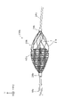
- FIG. 5 is an explanatory diagram showing a vertical cross-sectional configuration of the catheter 100c in which the dilator 20c in the third embodiment is in the dilated state.
- the lateral configuration of the dilator 20c which will be described later, is shown in the catheter 100c.
- the catheter 100c is a suction catheter that expands the dilator 20c toward a lesion (for example, cerebral infarction) in the blood vessel B and sucks the thrombus fragment Bc from the lesion.
- the catheter 100c includes a hollow shaft 10c, a tubular expansion body 20c attached to the tip of the shaft 10c, and a connector 30c attached to the base end of the shaft 10c. ..
- the shaft 10c is a cylindrical (for example, cylindrical) hollow body in which the tip and the base end are open. Inside the shaft 10c, a lumen Sc extending from the tip end to the base end of the shaft 10c is formed. The lumen Sc functions as a suction path that guides the thrombus piece Bc collected via the expansion body 20c to the proximal end side of the shaft 10c.
- resins such as polyamide, polyamide elastoma, polyolefin, polyester, and polyester elastoma
- superelastic alloys such as stainless steel (SUS304) and Ni—Ti alloy are used.
- the expansion body 20c is arranged substantially coaxially with the shaft 10c.
- the base end of the extension body 20c is connected to the tip end of the shaft 10c.
- the expansion body 20c is a braided body (mesh body) formed into a cylindrical shape by braiding a plurality of expansion strands 21c and 22c.
- the expansion strands 21c and 22c are examples of a plurality of strands within the scope of the claims.
- the expansion strands 21c and 22c intersect each other and are arranged in a mesh pattern.
- the winding directions of the expansion strands 21c and 22c are opposite to each other and are arranged so as to intersect each other.
- the expansion body 20c is formed so as to be able to expand and contract in the radial direction.
- both the expandability and the space occupancy of the dilator 20c can be achieved at the same time.
- Examples of the material for forming the expansion strands 21c and 22c include superelastic alloys such as stainless steel (SUS302, 304, 316) and Ni—Ti alloys, or materials having radiation impermeable properties (for example, tungsten and Co—). Metals such as Cr alloy) and resins such as polyethylene, polyurethane, polyurethane elastoma, polyamide, polyamide elastoma, polyolefin, polyester and polyester elastoma are used. Further, by using platinum as one of the forming materials of the expansion strands 21c and 22c, the visibility can be adjusted. The diameters of the expansion strands 21c and 22c are, for example, 50 ⁇ m.
- the eight expansion wires 21c and 22c constituting the expansion body 20c include a high-rigidity wire 33c having a relatively high rigidity and a low-rigidity wire 34c having a relatively low rigidity.
- FIG. 6 is a schematic view of the cross-sectional structure of the extended body 20c. In FIG. 6, only the cross-sectional configurations of the eight high-rigidity strands 33c and the low-rigidity strands 34c constituting the expansion body 20c are shown in an enlarged manner.
- the plurality of high-rigidity strands 33c are arranged at positions symmetrical with respect to the coaxial, and the plurality of low-rigidity strands 34c are coaxial. It is arranged symmetrically with respect to the relative.
- the high-rigidity strands 33c and the low-rigidity strands 34c are arranged so as to be alternately arranged in the circumferential direction of the expansion body 20c when viewed from the axial direction of the catheter 100c.
- the bias of the shape of the expansion body 20c can be suppressed as compared with the configuration in which at least one of the high-rigidity wire 33c and the low-rigidity wire 34c is asymmetrically arranged, and as a result, the thrombus piece Bc is expanded. It can be smoothly collected within 20c.
- each high-rigidity wire 33c is larger than the cross section of each low-rigidity wire 34c. Further, the outer shape of the cross section perpendicular to the length direction of each high-rigidity wire 33c and the outer shape of the cross section perpendicular to the length direction of each low-rigidity wire 34c are different from each other. Specifically, each high-rigidity wire 33c is a single wire, and each low-rigidity wire 34c is a stranded wire. Specifically, each low-rigidity wire 34c has a core wire 36c and a plurality of (for example, six) side wires 38c.
- Each low-rigidity wire 34c is formed by twisting six side wires 38c on the outer circumference of the core wire 36c. That is, each lateral line 38c is spirally arranged around the core wire 36c.
- the plurality of lateral lines 38c is an example of a plurality of wires within the scope of claims.
- the area of the cross section of one high-rigidity wire 33c is larger than the total cross section of the core wire 36c and the six lateral lines 38c constituting one low-rigidity wire 34c.
- the radial bending rigidity of the extension body 20c of the low-rigidity wire 34c can be effectively made lower than the bending rigidity of the high-rigidity wire 33c due to the difference in the area of the cross section.
- the high-rigidity wire 33 and the low-rigidity wire 34a can have different bending characteristics depending on the difference in the outer shape of the cross section.
- the low-rigidity wire 34c is a stranded wire, the flexibility of the low-rigidity wire 34c can be improved as compared with the configuration in which the low-rigidity wire 34c is a single wire.
- the outer diameter D1 of the tip of the expansion body 20c is larger than the outer diameter D2 of the base end of the expansion body 20c.
- the shape of the expanded body 20c at the time of expansion is a tapered shape in which the outer diameter increases toward the tip. As a result, the tip of the dilated body 20c is greatly opened, so that the thrombus fragment Bc located at the lesion can be easily collected in the dilated body 20c.
- the expansion body 20c is formed so as to be self-expandable in the radial direction by elastic deformation of a plurality of expansion strands 21c and 22c.
- the expansion body 20c is housed in a sheath (not shown) in a contracted state in which a plurality of expansion strands 21c and 22c are elastically deformed and guided to the vicinity of the lesion.
- the expansion body 20c is pushed out from the sheath to the tip side, the expansion body 20c is in the expanded state by self-expansion due to the restoring force of the plurality of expansion strands 21c and 22c (see FIG. 5). Thereby, the expanded body 20c can be changed from the contracted state to the expanded state by a relatively simple configuration.
- the plurality of expansion strands 21c and 22c come into contact with the wall surface B1 of the blood vessel B by the restoring force, so that damage to the wall surface B1 of the blood vessel B can be suppressed.
- the outer diameter D1 at the tip of the expansion body 20c is larger than the outer diameter D3 of the shaft 10c.
- the tip of the dilated body 20c is greatly opened, so that the thrombus fragment Bc located at the lesion can be easily collected in the dilated body 20c.
- the expansion body 20c is formed so as to be self-expandable, the strength required for the sheath can be increased by reducing the self-expansion force (elastic force of the expansion strands 21c and 22c) of the expansion body 20c. Since it can be reduced, the wall thickness of the sheath can be reduced.
- the outer diameter of the sheath is, for example, 2.2 mm
- the inner diameter is, for example, 1.8 mm.
- At least one of the inner peripheral surface and the outer peripheral surface of the expansion body 20c is covered with the induction film 60c.
- the induction film 60c is an example of a thin film within the scope of claims.
- the inner peripheral side and the outer peripheral side of the extended body 20c from the tip 62c to the base end 64c are covered with the guide film 60c over the entire circumference. Thereby, the thrombus fragment Bc collected in the expanded body 20c can be guided to the lumen Sc of the shaft 10c by the induction membrane 60c.
- the material for forming the inductive film 60c for example, resins such as polyethylene, polyurethane, polyurethane elastoma, polyamide, polyamide elastoma, polyolefin, polyester, and polyester elastoma are used.
- the thickness of 60c is, for example, 20 ⁇ m or more and 30 ⁇ m or less.
- the connector 30c is connected to a liquid discharge device for sucking the collected material collected in the shaft 10c via the expansion body 20c.
- the liquid discharge device is, for example, a syringe or a liquid feed pump.
- the catheter 100c provided with the liquid draining device syringe or liquid feeding pump
- both the expandability and the space occupancy of the dilator 20c can be achieved.
- FIG. 7 is an explanatory view schematically showing the lateral configuration of the catheter 100b in the modified example.
- an extension body 20b is connected to the tip end portion of the catheter 100b via a core wire 24b accommodated in the shaft 10b.
- the extension body 20b is arranged around the core wire 24b protruding from the shaft 10b.
- the extended body 20b is a cylindrical spiral body in which a plurality of spiral strands 21b having the same winding direction are arranged with a gap between them.
- the inner circumference of the proximal end side portion of the extended body 20b is covered with the induction film 60b.
- the induction film 60b is an example of a thin film within the scope of claims.
- An annular marker 26b is connected to the front end portion and the rear end portion of the expansion body 20b, respectively. For example, the marker 26b (marker 26b arranged on the right side in FIG.
- the marker 26b) arranged on the left side of the above is configured to be slidable in the length direction of the core wire 24b, and the core wire 24b is pulled to the rear side (left side in the figure) with respect to the shaft 10b, thereby leading the tip of the expansion body 20b. Since the distance between the markers 26b and 26b connected to the portion and the rear end portion is shortened, the expansion body 20b can be expanded.
- the plurality of strands 21b constituting the expansion body 20b are configured to include the strands having different radial bending rigidity of the expansion body 20b so that the expansion body 20b can be expanded. It is possible to achieve both sex and space occupancy.
- the catheters 100, 100a and 100b include a self-expandable dilator composed of elastic strands, and the dilator is tipped from the shaft 10. It may be configured to expand radially from the contracted state by being pushed out to the side.
- the expansion strands 21 and 22 and the strands 21b constituting the expansion bodies 20, 20a and 20b are not limited to single wires, and for example, a plurality of wires are twisted. It may be a twisted wire or a parallel wire in which a plurality of wires are arranged in parallel.
- the high-rigidity wire 33c constituting the expansion body 20c may be a stranded wire or a parallel wire
- the low-rigidity wire 34c may be a single wire or a parallel wire.
- the guide films 60 and 60b are formed in a tubular shape so as to cover the inner peripheral side of the proximal end side portion of the expanded bodies 20 and 20b over the entire circumference.
- the present invention is not limited to this, and a configuration may be used in which only a part of the inner peripheral side of the proximal end side portion of the expanded bodies 20 and 20b is covered in the circumferential direction.
- the guide films 60 and 60b may be configured to cover only the outer peripheral side of the proximal end side portion of the expanded bodies 20 and 20b (or cover both the inner peripheral side and the outer peripheral side).
- the induction film 60c may be configured to cover only one of the inner peripheral side and the outer peripheral side of the extended body 20c, or may be configured to cover only the proximal end side portion of the extended body 20c. good.
- the strands constituting the extended bodies 20, 20a to 20c include the high-rigidity strands 33, 33c and the low-rigidity strands 34, 34a, 34c, but the present invention is not limited to this, and further.
- a third wire having a rigidity different from that of the high-rigidity wire 33, 33c and the low-rigidity wire 34, 34a, 34c (for example, the rigidity is lower than that of the high-rigidity wire 33, 33c, and the low-rigidity wire 34, It may contain medium-rigidity strands higher than 34a and 34c).
- the high-rigidity strands 33, 33c and the low-rigidity strands 34, 34a, 34c may be the same number, but for example, the number of the high-rigidity strands 33, 33c is the low-rigidity strands 34, 34a. , 34c may be greater, or the number of high-rigidity strands 33, 33c may be less than the number of low-rigidity strands 34, 34a, 34c.
- the high-rigidity wire 33, 33c and the low-rigidity wire 34, 34a, 34c have different Young's modulus of the forming material, or the moment of inertia of area determined by the cross-sectional shape and size of the member. By making (at least one of the cross-sectional shape and the size of the cross-section) different, the bending rigidity in the radial direction can be made different.
- the high-rigidity strands 33, 33c and the low-rigidity strands 34, 34a, 34c may be arranged at asymmetric positions with respect to the axes of the catheters 100, 100a, 100c, respectively.
- each member in the catheters 100, 100a to 100c of the above embodiment is merely an example and can be variously deformed.
Landscapes
- Health & Medical Sciences (AREA)
- Life Sciences & Earth Sciences (AREA)
- Veterinary Medicine (AREA)
- Public Health (AREA)
- General Health & Medical Sciences (AREA)
- Surgery (AREA)
- Engineering & Computer Science (AREA)
- Biomedical Technology (AREA)
- Heart & Thoracic Surgery (AREA)
- Animal Behavior & Ethology (AREA)
- Molecular Biology (AREA)
- Medical Informatics (AREA)
- Nuclear Medicine, Radiotherapy & Molecular Imaging (AREA)
- Vascular Medicine (AREA)
- Orthopedic Medicine & Surgery (AREA)
- Biophysics (AREA)
- Pulmonology (AREA)
- Anesthesiology (AREA)
- Hematology (AREA)
- Media Introduction/Drainage Providing Device (AREA)
Priority Applications (1)
| Application Number | Priority Date | Filing Date | Title |
|---|---|---|---|
| JP2022558987A JPWO2022091784A1 (https=) | 2020-10-26 | 2021-10-13 |
Applications Claiming Priority (2)
| Application Number | Priority Date | Filing Date | Title |
|---|---|---|---|
| JP2020-178934 | 2020-10-26 | ||
| JP2020178934 | 2020-10-26 |
Publications (1)
| Publication Number | Publication Date |
|---|---|
| WO2022091784A1 true WO2022091784A1 (ja) | 2022-05-05 |
Family
ID=81383788
Family Applications (1)
| Application Number | Title | Priority Date | Filing Date |
|---|---|---|---|
| PCT/JP2021/037876 Ceased WO2022091784A1 (ja) | 2020-10-26 | 2021-10-13 | カテーテル |
Country Status (2)
| Country | Link |
|---|---|
| JP (1) | JPWO2022091784A1 (https=) |
| WO (1) | WO2022091784A1 (https=) |
Cited By (5)
| Publication number | Priority date | Publication date | Assignee | Title |
|---|---|---|---|---|
| US12403296B2 (en) | 2018-05-30 | 2025-09-02 | Kardion Gmbh | Apparatus for anchoring a ventricular assist system in a blood vessel, operating method, production method for producing an apparatus and ventricular assist system |
| US12478775B2 (en) | 2018-07-09 | 2025-11-25 | Kardion Gmbh | Cardiac assist system, and method for monitoring the integrity of a retaining structure of a cardiac assist system |
| US12576263B2 (en) | 2018-05-30 | 2026-03-17 | Kardion Gmbh | Device for attaching a heart support system to an insertion device, and method for producing same |
| US12589237B2 (en) | 2020-11-20 | 2026-03-31 | Kardion Gmbh | Mechanical circulatory support system with guidewire aid |
| US12599749B2 (en) | 2018-05-30 | 2026-04-14 | Kardion Gmbh | Controllable insertion sleeve |
Citations (6)
| Publication number | Priority date | Publication date | Assignee | Title |
|---|---|---|---|---|
| JP2002113010A (ja) * | 2000-10-11 | 2002-04-16 | Asahi Optical Co Ltd | 内視鏡用バスケット型回収具 |
| JP2005230132A (ja) * | 2004-02-18 | 2005-09-02 | Asahi Intecc Co Ltd | 医療用処置具 |
| JP2009066178A (ja) * | 2007-09-13 | 2009-04-02 | Goodman Co Ltd | 吸引用カテーテル |
| JP2013512735A (ja) * | 2009-12-02 | 2013-04-18 | シュアファイア メディカル,インコーポレイティド | 塞栓剤逆流からの防御のための微小弁装置及びその使用方法 |
| WO2018147449A1 (ja) * | 2017-02-10 | 2018-08-16 | 川澄化学工業株式会社 | 異物除去デバイス、異物除去用カテーテル及び異物回収システム |
| JP2020062317A (ja) * | 2018-10-19 | 2020-04-23 | 朝日インテック株式会社 | カテーテル |
-
2021
- 2021-10-13 WO PCT/JP2021/037876 patent/WO2022091784A1/ja not_active Ceased
- 2021-10-13 JP JP2022558987A patent/JPWO2022091784A1/ja active Pending
Patent Citations (6)
| Publication number | Priority date | Publication date | Assignee | Title |
|---|---|---|---|---|
| JP2002113010A (ja) * | 2000-10-11 | 2002-04-16 | Asahi Optical Co Ltd | 内視鏡用バスケット型回収具 |
| JP2005230132A (ja) * | 2004-02-18 | 2005-09-02 | Asahi Intecc Co Ltd | 医療用処置具 |
| JP2009066178A (ja) * | 2007-09-13 | 2009-04-02 | Goodman Co Ltd | 吸引用カテーテル |
| JP2013512735A (ja) * | 2009-12-02 | 2013-04-18 | シュアファイア メディカル,インコーポレイティド | 塞栓剤逆流からの防御のための微小弁装置及びその使用方法 |
| WO2018147449A1 (ja) * | 2017-02-10 | 2018-08-16 | 川澄化学工業株式会社 | 異物除去デバイス、異物除去用カテーテル及び異物回収システム |
| JP2020062317A (ja) * | 2018-10-19 | 2020-04-23 | 朝日インテック株式会社 | カテーテル |
Cited By (5)
| Publication number | Priority date | Publication date | Assignee | Title |
|---|---|---|---|---|
| US12403296B2 (en) | 2018-05-30 | 2025-09-02 | Kardion Gmbh | Apparatus for anchoring a ventricular assist system in a blood vessel, operating method, production method for producing an apparatus and ventricular assist system |
| US12576263B2 (en) | 2018-05-30 | 2026-03-17 | Kardion Gmbh | Device for attaching a heart support system to an insertion device, and method for producing same |
| US12599749B2 (en) | 2018-05-30 | 2026-04-14 | Kardion Gmbh | Controllable insertion sleeve |
| US12478775B2 (en) | 2018-07-09 | 2025-11-25 | Kardion Gmbh | Cardiac assist system, and method for monitoring the integrity of a retaining structure of a cardiac assist system |
| US12589237B2 (en) | 2020-11-20 | 2026-03-31 | Kardion Gmbh | Mechanical circulatory support system with guidewire aid |
Also Published As
| Publication number | Publication date |
|---|---|
| JPWO2022091784A1 (https=) | 2022-05-05 |
Similar Documents
| Publication | Publication Date | Title |
|---|---|---|
| US10695531B2 (en) | Balloon catheter and medical elongated body | |
| WO2022091784A1 (ja) | カテーテル | |
| TWI774832B (zh) | 導管及導管套件 | |
| JP5769992B2 (ja) | カテーテル | |
| JP7241157B2 (ja) | 医療用長尺体および医療器具セット | |
| EP2389973A1 (en) | Balloon catheter | |
| JP2017523020A (ja) | 経頸動脈神経血管カテーテル | |
| US20240325045A1 (en) | Elongated medical body | |
| JP5137846B2 (ja) | モジュール構造の医療用カテーテル | |
| US20220088354A1 (en) | Balloon catheter | |
| JP2012223207A (ja) | バルーンカテーテル | |
| JPWO2019198210A1 (ja) | カテーテル | |
| WO2018163564A1 (ja) | カテーテル | |
| JP2025019272A (ja) | サポートカテーテルおよびチューブ | |
| JP2007130116A (ja) | カテーテル | |
| JP2020049131A (ja) | 医療用長尺体 | |
| US20230129088A1 (en) | Catheter | |
| JP2020039377A (ja) | ガイドワイヤ | |
| JP7076044B2 (ja) | バルーンカテーテル | |
| WO2022249385A1 (ja) | カテーテル | |
| CN113939328A (zh) | 导管 | |
| CN114432579B (zh) | 具有可变横截面形状的导管编织线 | |
| JP2019213619A (ja) | 医療用チューブおよびその製造方法 | |
| JP2022112791A (ja) | カテーテル | |
| JP2022035226A (ja) | 医療用長尺体および医療器具セット |
Legal Events
| Date | Code | Title | Description |
|---|---|---|---|
| 121 | Ep: the epo has been informed by wipo that ep was designated in this application |
Ref document number: 21885903 Country of ref document: EP Kind code of ref document: A1 |
|
| NENP | Non-entry into the national phase |
Ref country code: DE |
|
| WWE | Wipo information: entry into national phase |
Ref document number: 2022558987 Country of ref document: JP |
|
| 122 | Ep: pct application non-entry in european phase |
Ref document number: 21885903 Country of ref document: EP Kind code of ref document: A1 |