WO2022091784A1 - Catheter - Google Patents
Catheter Download PDFInfo
- Publication number
- WO2022091784A1 WO2022091784A1 PCT/JP2021/037876 JP2021037876W WO2022091784A1 WO 2022091784 A1 WO2022091784 A1 WO 2022091784A1 JP 2021037876 W JP2021037876 W JP 2021037876W WO 2022091784 A1 WO2022091784 A1 WO 2022091784A1
- Authority
- WO
- WIPO (PCT)
- Prior art keywords
- catheter
- rigidity
- strands
- wire
- low
- Prior art date
Links
- 238000005452 bending Methods 0.000 claims abstract description 19
- 230000002093 peripheral effect Effects 0.000 claims description 20
- 239000007788 liquid Substances 0.000 claims description 13
- 239000010409 thin film Substances 0.000 claims description 6
- 230000005489 elastic deformation Effects 0.000 claims description 3
- 230000003902 lesion Effects 0.000 description 41
- 239000000463 material Substances 0.000 description 22
- 239000010408 film Substances 0.000 description 21
- 210000004204 blood vessel Anatomy 0.000 description 20
- 208000029497 Elastoma Diseases 0.000 description 17
- 229920000728 polyester Polymers 0.000 description 14
- 239000004952 Polyamide Substances 0.000 description 12
- 229920002647 polyamide Polymers 0.000 description 12
- 230000006698 induction Effects 0.000 description 11
- 229910045601 alloy Inorganic materials 0.000 description 9
- 239000000956 alloy Substances 0.000 description 9
- 229920002635 polyurethane Polymers 0.000 description 9
- 239000004814 polyurethane Substances 0.000 description 9
- 208000007536 Thrombosis Diseases 0.000 description 8
- 239000011347 resin Substances 0.000 description 8
- 229920005989 resin Polymers 0.000 description 8
- 239000012634 fragment Substances 0.000 description 6
- 239000003550 marker Substances 0.000 description 6
- 238000000034 method Methods 0.000 description 6
- 229920000098 polyolefin Polymers 0.000 description 6
- 239000010935 stainless steel Substances 0.000 description 6
- 229910001220 stainless steel Inorganic materials 0.000 description 6
- 238000010586 diagram Methods 0.000 description 5
- KHYBPSFKEHXSLX-UHFFFAOYSA-N iminotitanium Chemical compound [Ti]=N KHYBPSFKEHXSLX-UHFFFAOYSA-N 0.000 description 5
- 229910052751 metal Inorganic materials 0.000 description 5
- 239000002184 metal Substances 0.000 description 5
- 229910001000 nickel titanium Inorganic materials 0.000 description 5
- 239000004698 Polyethylene Substances 0.000 description 4
- 210000004351 coronary vessel Anatomy 0.000 description 4
- 238000006073 displacement reaction Methods 0.000 description 4
- 230000001939 inductive effect Effects 0.000 description 4
- 238000012986 modification Methods 0.000 description 4
- 230000004048 modification Effects 0.000 description 4
- -1 polyethylene Polymers 0.000 description 4
- 229920000573 polyethylene Polymers 0.000 description 4
- 238000004804 winding Methods 0.000 description 4
- 230000010339 dilation Effects 0.000 description 3
- WFKWXMTUELFFGS-UHFFFAOYSA-N tungsten Chemical compound [W] WFKWXMTUELFFGS-UHFFFAOYSA-N 0.000 description 3
- 229910052721 tungsten Inorganic materials 0.000 description 3
- 239000010937 tungsten Substances 0.000 description 3
- 229910000599 Cr alloy Inorganic materials 0.000 description 2
- 208000031481 Pathologic Constriction Diseases 0.000 description 2
- 230000002159 abnormal effect Effects 0.000 description 2
- 230000015572 biosynthetic process Effects 0.000 description 2
- 238000009954 braiding Methods 0.000 description 2
- 230000002308 calcification Effects 0.000 description 2
- 230000001684 chronic effect Effects 0.000 description 2
- 230000007423 decrease Effects 0.000 description 2
- 238000003780 insertion Methods 0.000 description 2
- 230000037431 insertion Effects 0.000 description 2
- 239000012528 membrane Substances 0.000 description 2
- 150000002739 metals Chemical class 0.000 description 2
- BASFCYQUMIYNBI-UHFFFAOYSA-N platinum Chemical compound [Pt] BASFCYQUMIYNBI-UHFFFAOYSA-N 0.000 description 2
- 230000005855 radiation Effects 0.000 description 2
- 230000036262 stenosis Effects 0.000 description 2
- 208000037804 stenosis Diseases 0.000 description 2
- 239000008280 blood Substances 0.000 description 1
- 210000004369 blood Anatomy 0.000 description 1
- 230000017531 blood circulation Effects 0.000 description 1
- 206010008118 cerebral infarction Diseases 0.000 description 1
- 208000026106 cerebrovascular disease Diseases 0.000 description 1
- 230000006378 damage Effects 0.000 description 1
- 230000006866 deterioration Effects 0.000 description 1
- 230000000916 dilatatory effect Effects 0.000 description 1
- 230000000694 effects Effects 0.000 description 1
- 239000012530 fluid Substances 0.000 description 1
- 239000002504 physiological saline solution Substances 0.000 description 1
- 229910052697 platinum Inorganic materials 0.000 description 1
- 229920003225 polyurethane elastomer Polymers 0.000 description 1
- 230000002966 stenotic effect Effects 0.000 description 1
Images


Classifications
-
- A—HUMAN NECESSITIES
- A61—MEDICAL OR VETERINARY SCIENCE; HYGIENE
- A61B—DIAGNOSIS; SURGERY; IDENTIFICATION
- A61B17/00—Surgical instruments, devices or methods, e.g. tourniquets
- A61B17/22—Implements for squeezing-off ulcers or the like on the inside of inner organs of the body; Implements for scraping-out cavities of body organs, e.g. bones; Calculus removers; Calculus smashing apparatus; Apparatus for removing obstructions in blood vessels, not otherwise provided for
-
- A—HUMAN NECESSITIES
- A61—MEDICAL OR VETERINARY SCIENCE; HYGIENE
- A61M—DEVICES FOR INTRODUCING MEDIA INTO, OR ONTO, THE BODY; DEVICES FOR TRANSDUCING BODY MEDIA OR FOR TAKING MEDIA FROM THE BODY; DEVICES FOR PRODUCING OR ENDING SLEEP OR STUPOR
- A61M25/00—Catheters; Hollow probes
Definitions
- the techniques disclosed herein relate to catheters with dilators.
- the catheter comprises a hollow shaft and an extension connected to the tip of the shaft.
- the extended body is a tubular body formed so as to be expandable and contractible in the radial direction by a plurality of strands.
- Some catheters with dilators are used as follows. If the lesion is very hard, such as chronic total occlusion (CTO) or calcification stenosis, the guide wire inserted from one side may not be able to penetrate the lesion. In this case, the tip of the catheter is guided to the lesion in a state where the dilator is contracted, and the dilator is inserted and expanded in the space formed halfway of the lesion. Next, the retro guide wire is inserted into the lesion from the side opposite to the guide wire. The tip of the inserted retro guide wire enters the dilated body through the gap of the dilated body and then into the shaft, resulting in the formation of a through hole in the lesion. As a result, treatment of the lesion can be advanced.
- CTO chronic total occlusion
- calcification stenosis the guide wire inserted from one side may not be able to penetrate the lesion.
- the tip of the catheter is guided to the lesion in a state where the
- the rigidity of all the wires constituting the dilated body is the same as each other.
- the rigidity of the plurality of strands constituting the dilated body is relatively low, the dilating force for expanding the blood vessel or the lesion portion by changing the dilated body from the contracted state to the dilated state becomes weak.
- the rigidity of the plurality of strands constituting the dilated body is relatively high, the dilated body is deformed into a shape different from the shape of the wall surface such as a blood vessel when the dilated body is in the expanded state, and the dilated body is a blood vessel.
- the performance (space occupancy) that occupies the space in the same area becomes low.
- the space occupancy is low, the gap between the outer periphery of the dilated body and the wall surface such as a blood vessel becomes wide, and as a result, for example, blood easily flows into the same gap, and the suction force of the dilated body decreases.
- the tip of the retro guide wire easily gets into the same gap and cannot smoothly enter the dilated body.
- This specification discloses a technique capable of solving at least a part of the above-mentioned problems.
- the catheter disclosed in the present specification is a catheter, which is formed by a hollow shaft and a plurality of strands connected to the tip of the shaft so as to be expandable and contractible in the radial direction of the catheter.
- the plurality of strands constituting the extended body include a cylindrical extended body, and the expanded body has a high-rigidity wire having a relatively high radial bending rigidity and the bending rigidity of the expanded body. Includes low-rigidity strands that are lower than high-rigidity strands.
- the expandability to dilate a blood vessel or a lesion is high as compared with a configuration in which the rigidity of all the strands constituting the dilator is relatively low.
- the rigidity of all the strands constituting the dilated body is relatively high, it is deformed according to the shape of the wall surface of the blood vessel or the like, and the gap between the outer periphery of the dilated body and the wall surface of the blood vessel or the like is formed. Since it becomes narrower, the space occupancy of the dilated body occupying the space in the blood vessel or the like is increased. That is, according to this catheter, it is possible to achieve both the expandability of the dilator and the space occupancy.
- the plurality of strands may be arranged spirally with a gap between them.
- both dilatability and space occupancy of the dilator can be achieved at the same time.
- the plurality of strands may be arranged so as to intersect each other in a mesh pattern.
- both dilatability and space occupancy of the dilator can be achieved at the same time.
- the low-rigidity wire may have a flat shape in which the width in the radial direction is smaller than the width in the circumferential direction of the dilator. According to this catheter, the low-rigidity wire having a relatively low rigidity is more likely to be displaced in the circumferential direction than the configuration in which the radial width of the low-rigidity wire is equal to or larger than the circumferential width. Since the gap between the outer periphery of the dilated body and the wall surface of the blood vessel or the like is narrowed, the space occupancy of the dilated body can be improved more effectively.
- the plurality of strands include the plurality of the high-rigidity strands and the plurality of the low-rigidity strands, and the plurality of strands are viewed from the axial direction of the dilator.
- the high-rigidity strands may be arranged at positions symmetrical with respect to the axis, and the plurality of low-rigidity strands may be arranged at positions symmetrical with respect to the axis. According to this catheter, it is possible to suppress the bias of the shape of the dilated body as compared with the configuration in which at least one of the high-rigidity wire and the low-rigidity wire is asymmetrically arranged.
- the area of the cross section perpendicular to the length direction of the high-rigidity wire may be larger than the area of the cross section perpendicular to the length direction of the low-rigidity wire.
- the difference in the area of the cross section perpendicular to the length direction makes it possible to effectively lower the flexural rigidity of the extension body of the low-rigidity wire in the radial direction than the bending rigidity of the high-rigidity wire.
- the outer shape of the cross section perpendicular to the length direction of the high-rigidity wire and the outer shape of the cross section perpendicular to the length direction of the low-rigidity wire are different from each other. According to this catheter, a high-rigidity wire and a low-rigidity wire can have different bending characteristics depending on the difference in outer shape.
- the plurality of low-rigidity strands may be configured to include a stranded wire obtained by twisting a plurality of wires. According to this catheter, the flexibility of the low-rigidity wire can be improved as compared with the configuration in which the low-rigidity wire is a single wire.
- the outer diameter of the tip of the dilator may be larger than the outer diameter of the proximal end of the dilator. According to this catheter, the recovered material can be easily recovered in the dilated body.
- the dilator may be formed so as to be self-expandable in the radial direction by elastic deformation of the plurality of strands. According to this catheter, the dilated body can be changed from the contracted state to the dilated state by a relatively simple configuration.
- the outer diameter of the tip of the dilator may be larger than the outer diameter of the shaft. According to this catheter, the recovered material can be easily recovered in the dilated body.
- At least one of the inner peripheral surface and the outer peripheral surface of the dilator may be covered with a thin film.
- the recovered material for example, a thrombus fragment, a retro guide wire, etc.
- the catheter may be further provided with a liquid draining device connected to the proximal end side of the shaft. According to this catheter, in a catheter provided with a liquid draining device, it is possible to achieve both expandability and space occupancy of the dilator.
- the liquid draining device may be configured to be a syringe or a liquid feeding pump. According to this catheter, in a catheter provided with a syringe or a liquid feeding pump, it is possible to achieve both expandability and space occupancy of the dilator.
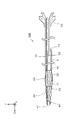
- FIG. 1 is an explanatory diagram schematically showing a vertical cross-sectional configuration of the catheter 100 in the first embodiment.
- the lateral configuration of the dilator 20 described later in the catheter 100 is shown.
- the vertical cross section of the catheter 100 means a cross section (YZ cross section in FIG. 1) parallel to the axial direction (longitudinal direction Z-axis direction in FIG. 1) of the catheter 100.
- the Z-axis negative direction side (the side of the connector 30 described later) is the proximal end side (proximal side) operated by a technician such as a doctor, and the Z-axis positive direction side (opposite to the connector 30).
- the side) is the distal side that is inserted into the body.
- FIG. 1 shows a state in which the catheter 100 is in a straight line parallel to the Z-axis direction as a whole, but the catheter 100 has sufficient flexibility to be curved.
- the catheter 100 is a medical device inserted into a blood vessel or the like for treating or inspecting a lesion L in the blood vessel or the like.
- the catheter 100 includes a dilator 20 at the tip thereof, and is a retro guide wire inserted into the lesion L from the side opposite to the catheter 100 in order to form a through hole in the lesion L.
- the tip is made to enter the expansion body 20 and captured.
- the catheter 100 includes a hollow shaft 10, a tubular expansion body 20 attached to the tip of the shaft 10, and a connector 30 attached to the base of the shaft 10. ..
- the shaft 10 is a cylindrical (for example, cylindrical) hollow body in which the tip and the base end are open.
- the "cylindrical shape" include a cylindrical shape and a square tubular shape, and a taper or unevenness may be formed in a part thereof in the axial direction.
- a lumen S extending from the tip end to the base end of the shaft 10 is formed inside the shaft 10.
- a fluid such as physiological saline to be injected into an abnormal blood vessel is supplied to the lumen S, or a guide wire (not shown) is inserted through the lumen S.
- a port 12 is formed through the side wall of the shaft 10.
- a resin such as polyamide, polyamide elastoma, polyolefin, polyester, polyester elastoma, or a superelastic alloy such as stainless steel (SUS304) or Ni—Ti alloy is used.
- the expansion body 20 is arranged substantially coaxially with the shaft 10.
- the base end of the extension body 20 is connected to the tip end of the shaft 10.
- the expansion body 20 is a braided body (mesh body) formed into a cylindrical shape by braiding a plurality of expansion strands.
- the expansion body 20 has expansion strands 21 and 22.
- the expansion strands 21 and 22 are examples of a plurality of strands within the scope of the claims.
- the expansion strands 21 and 22 are spirally arranged around the central axis of the catheter 100.
- the winding directions of the expansion strands 21 and 22 are opposite to each other and are arranged so as to intersect each other. With such a configuration, the expansion body 20 is formed so as to be able to expand and contract in the radial direction.
- the material for forming the expansion strands 21 and 22 include superelastic alloys such as stainless steel (SUS302, 304,316) and Ni—Ti alloys, or materials having radiation impermeable properties (for example, tungsten and Co—).
- Metals such as Cr alloy
- resins such as polyethylene, polyurethane, polyurethane elastoma, polyamide, polyamide elastoma, polyolefin, polyester and polyester elastoma are used.
- the expansion strands 21 and 22 are single wires.
- the tip tip 40 is joined to the tip of the extension body 20.
- the tip tip 40 has a tubular shape, and the shape of the tip portion of the tip tip 40 is a tapered shape in which the outer diameter decreases toward the tip.
- the insertion hole 42 formed in the tip tip 40 communicates with the space on the inner peripheral side of the expansion body 20.
- a flexible resin such as polyurethane or polyurethane elastomer is used.
- the tip of the core wire 50 is joined to the base end of the tip tip 40.
- the core wire 50 is a linear member, and is inserted into a space on the inner peripheral side of the expansion body 20 and a lumen S of the shaft 10.
- the core wire 50 is, for example, a tapered metal wire having a circular cross section and a smaller outer diameter toward the tip.
- a thin and flexible guide film 60 is formed on the proximal end side portion of the extended body 20.
- the induction film 60 is an example of a thin film within the scope of claims.
- the inductive film 60 is formed in a cylindrical shape so as to cover the inner peripheral side and the outer peripheral side of the proximal end side portion of the extended body 20 over the entire circumference. Specifically, the entire proximal end side portion (expansion strand) of the expansion body 20 is embedded in the induction film 60.
- the tip 62 of the guide film 60 extends axially to the vicinity of the center of the expansion body 20, and the proximal end 64 of the guide film 60 extends to the tip of the shaft 10.
- resins such as polyethylene, polyurethane, polyurethane elastoma, polyamide, polyamide elastoma, polyolefin, polyester, and polyester elastoma are used.
- FIG. 2 is a schematic view of the cross-sectional structure of the extended body 20.
- the cross section of the extended body 20 means a cross section (XY cross section in FIG. 1) perpendicular to the axial direction (Z axis direction in FIG. 1) of the catheter 100.
- FIG. 2 (a) shows the expanded state of the dilated body 20 before being inserted into the lesion portion L
- FIGS. 2 (b) and 2 (c) show the balloon dilated cavity L1 described later in the lesion portion L.
- the expanded state of the expanded body 20 in the state of being inserted into is shown.
- the eight expansion wires 21 and 22 constituting the expansion body 20 include a high-rigidity wire 33 having a relatively high rigidity and a low-rigidity wire 34 having a relatively low rigidity.
- the high-rigidity wire 33 and the low-rigidity wire 34 have substantially the same cross-sectional shape and cross-sectional area.
- the high-rigidity wire 33 is formed of a material having a higher Young's modulus than the low-rigidity wire 34, such as a metal such as tungsten or stainless steel.
- the low-rigidity strand 34 is formed of a metal such as stainless steel or Ni—Ti alloy, or a resin such as polyester or polyester elastoma.
- the materials of the high-rigidity wire 33 and the low-rigidity wire 34 are exemplified, but if the material is selected so as to cause a difference in rigidity between the high-rigidity wire 33 and the low-rigidity wire 34, the high-rigidity wire 33 and the material are selected.
- the material of the low-rigidity wire 34 is not limited.
- the plurality of high-rigidity strands 33 are arranged at positions symmetrical with respect to the coaxial when viewed from the axial direction of the catheter 100, and the plurality of low-rigidity strands 34 are coaxial. It is arranged symmetrically with respect to the relative.
- the strands having the same rigidity may be arranged so as to intersect each other, or the strands having the same rigidity may be arranged in parallel without intersecting each other.
- all the expansion strands 21 may be the high-rigidity strands 33
- all the expansion strands 22 may be the low-rigidity strands 34
- the expansion strands 21 and 22 may be any of them.
- the high-rigidity wire 33 and the low-rigidity wire 34 may be included. When the strands having different rigidity intersect with each other, the intersecting portions of the strands may not be joined and may be movable independently of each other.
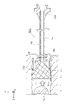
- FIG. 3 is an explanatory view showing a vertical cross-sectional configuration of the catheter 100 in which the dilated body 20 is in the dilated state. In FIG. 3, the lateral configuration of the dilator 20 of the catheter 100 is shown.
- the lesion L formed in the blood vessel B is partially very hard, such as chronic complete occlusion or calcification stenosis, one side (Z-axis negative side in FIG. 3 or less), A guide wire (not shown) inserted from (referred to as "ante side") may not be able to penetrate the lesion L.
- the hole formed on the ante side of the lesion portion L is the other side of the lesion portion L (the Z-axis positive direction side in FIG. 3).
- it does not penetrate to the "retro side” and remains at a position in the middle of the lesion L.
- a balloon catheter (not shown) is guided from the ante side to the lesion L via a guide wire inserted halfway through the lesion L. Then, the contracted balloon in the balloon catheter is inserted into the hole formed in the lesion L to expand the balloon. As a result, the balloon dilated cavity L1 is formed on the ante side of the lesion L.
- the balloon catheter is withdrawn from the balloon dilatation cavity L1 of the lesion L, and instead, the contracted dilated body 20 (see FIG. 1) in the catheter 100 is inserted, and the dilated body 20 is inserted as shown in FIG. Expand.
- the dilated body 20 is held in the balloon dilated cavity L1.
- the retro guide wire 80 is inserted from, for example, the left coronary artery, and is inserted from the retro side of the lesion L via the collateral channel (collateral channel) formed so as to connect the left coronary artery to the right coronary artery.
- the tip of the retro guide wire 80 can reach the balloon dilation cavity L1 through a relatively soft portion on the retro side of the lesion L.
- the positions where the tip of the retro guide wire 80 enters in the balloon dilation cavity L1 are various and difficult to predict.
- the dilated body 20 in the expanded state is inserted in the balloon dilated cavity L1. Therefore, the tip of the retro guide wire 80 is inserted into any one of the plurality of gaps (mesh) formed in the expansion body 20 (for example, P in FIG. 3) and captured.
- the tip of the retro guide wire 80 inserted into the expansion body 20 is guided into the expansion body 20 by the induction film 60. As a result, a through hole is formed in the lesion L. After that, for example, a balloon catheter can be inserted from the retro side of the lesion L to expand the lesion L, and the like can be advanced.
- the plurality of expansion strands 21 and 22 constituting the expansion body 20 include the high-rigidity strands 33 and the low-rigidity strands 34. Therefore, for example, the expandability of expanding the balloon expansion cavity L1 is higher than that of the configuration in which the rigidity of all the expansion strands 21 and 22 constituting the expansion body 20 is relatively low. Further, compared to the configuration in which the rigidity of all the expansion strands 21 and 22 constituting the expansion body 20 is relatively high, the expansion body 20 is deformed according to the shape of the wall surface of the balloon expansion cavity L1, and the expansion body 20 is formed in the lesion portion L. The space occupancy that occupies the inner space is high.
- a force for expanding the balloon dilated cavity L1 is applied by the high-rigidity strand 33 in the balloon dilated cavity L1.
- the low-rigidity wire 34 is deformed according to the distorted wall surface shape of the lesion portion L, so that the formation of a gap between the outer periphery of the extended body 20 and the wall surface of the lesion portion L is suppressed.
- the tip of the retro guide wire 80 can smoothly enter the expansion body 20 without getting lost in the gap. That is, according to the present embodiment, it is possible to achieve both the expandability and the space occupancy of the expansion body 20.
- the expansion strands 21 and 22 are arranged in a mesh pattern so as to intersect each other (see FIGS. 1 and 2). According to the present embodiment, in the catheter 100 provided with such a network-like dilator 20, both the expandability and the space occupancy of the dilator 20 can be achieved at the same time.
- the plurality of high-rigidity strands 33 are arranged at positions symmetrical with respect to the coaxial when viewed from the axial direction of the catheter 100, and the plurality of low-rigidity strands 34 are arranged with respect to the coaxial. (See FIG. 2A). Therefore, the bias of the shape of the expansion body 20 can be suppressed as compared with the configuration in which at least one of the high-rigidity wire 33 and the low-rigidity wire 34 is asymmetrically arranged, and as a result, the retro guide wire 80 The tip portion can be smoothly entered into the expansion body 20.
- the inner peripheral side of the proximal end side portion of the extended body 20 is covered with the guide film 60 over the entire circumference.
- the tip of the retro guide wire 80 inserted in the expansion body 20 can be guided into the expansion body 20 by the guide film 60.
- FIG. 4 is a schematic view of the cross-sectional configuration of the extended body 20a of the catheter 100a in the second embodiment.
- FIG. 4 only the cross-sectional configurations of the eight high-rigidity strands 33 and the low-rigidity strands 34a constituting the expansion body 20 are shown in an enlarged manner.
- the same configurations as those of the catheter 100 of the first embodiment described above are designated by the same reference numerals, and the description thereof will be omitted.
- the low-rigidity wire 34a is a flat shape in which the radial width of the expansion body 20a (catheter 100a) is smaller than the circumferential width of the expansion body 20a. Therefore, the low-rigidity wire 34a, which has a relatively low rigidity, is more likely to be displaced in the radial direction than the configuration in which the radial width of the low-rigidity wire 34a is equal to or larger than the circumferential width. Since the gap between the outer periphery of the expansion body 20a and the wall surface of the balloon expansion cavity L1 is narrowed, the space occupancy of the expansion body 20a can be improved more effectively.
- the low-rigidity wire 34a is difficult to be displaced in the circumferential direction of the expansion body 20a, the low-rigidity wire 34a is displaced in the circumferential direction and another wire (high-rigidity wire 33, low-rigidity wire 34a). It is possible to suppress the deterioration of the insertability of the retro guide wire 80 due to the narrowing of the gap between the two.
- cross section The area of the cross section perpendicular to the length direction of each high-rigidity wire 33 (hereinafter referred to as “cross section”) is larger than the area of the cross section of each low-rigidity wire 34a.
- cross section The area of the cross section perpendicular to the length direction of each high-rigidity wire 33 (hereinafter referred to as “cross section”) is larger than the area of the cross section of each low-rigidity wire 34a.
- the outer shape of the cross section perpendicular to the length direction of each high-rigidity wire 33 and the outer shape of the cross section perpendicular to the length direction of each low-rigidity wire 34a are different from each other.
- the outer shape of each high-rigidity wire 33 is substantially circular
- the outer shape of each low-rigidity wire 34a is substantially rectangular.
- the high-rigidity wire 33 and the low-rigidity wire 34a can have different bending characteristics depending on the difference in outer shape.
- the high-rigidity wire 33 has a bending characteristic in which the degree of freedom of displacement in the circumferential direction of the expansion body 20a is equivalent to the degree of freedom of displacement in the radial direction.
- the low-rigidity wire 34a has a bending characteristic in which the degree of freedom of displacement in the circumferential direction of the extended body 20a is lower than the degree of freedom of displacement in the radial direction.
- the ratio of the radial width to the circumferential width of the low-rigidity wire 34a is lower than the ratio of the radial width to the circumferential width of the high-rigidity wire 33. That is, the low-rigidity wire 34a has higher radial flatness than the high-rigidity wire 33. Therefore, the radial bending rigidity of the low-rigidity wire 34a is lower than the radial bending rigidity of the high-rigidity wire 33.
- the material for forming the high-rigidity wire 33 and the low-rigidity wire 34a is the same.
- the radial width of the low-rigidity wire 34a is smaller than the radial width of the high-rigidity wire 33, and the circumferential width of the low-rigidity wire 34a is the circumferential width of the high-rigidity wire 33. It is almost the same. As a result, it is possible to prevent the gap between the high-rigidity wire 33 and the low-rigidity wire 34a from becoming narrow.
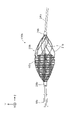
- FIG. 5 is an explanatory diagram showing a vertical cross-sectional configuration of the catheter 100c in which the dilator 20c in the third embodiment is in the dilated state.
- the lateral configuration of the dilator 20c which will be described later, is shown in the catheter 100c.
- the catheter 100c is a suction catheter that expands the dilator 20c toward a lesion (for example, cerebral infarction) in the blood vessel B and sucks the thrombus fragment Bc from the lesion.
- the catheter 100c includes a hollow shaft 10c, a tubular expansion body 20c attached to the tip of the shaft 10c, and a connector 30c attached to the base end of the shaft 10c. ..
- the shaft 10c is a cylindrical (for example, cylindrical) hollow body in which the tip and the base end are open. Inside the shaft 10c, a lumen Sc extending from the tip end to the base end of the shaft 10c is formed. The lumen Sc functions as a suction path that guides the thrombus piece Bc collected via the expansion body 20c to the proximal end side of the shaft 10c.
- resins such as polyamide, polyamide elastoma, polyolefin, polyester, and polyester elastoma
- superelastic alloys such as stainless steel (SUS304) and Ni—Ti alloy are used.
- the expansion body 20c is arranged substantially coaxially with the shaft 10c.
- the base end of the extension body 20c is connected to the tip end of the shaft 10c.
- the expansion body 20c is a braided body (mesh body) formed into a cylindrical shape by braiding a plurality of expansion strands 21c and 22c.
- the expansion strands 21c and 22c are examples of a plurality of strands within the scope of the claims.
- the expansion strands 21c and 22c intersect each other and are arranged in a mesh pattern.
- the winding directions of the expansion strands 21c and 22c are opposite to each other and are arranged so as to intersect each other.
- the expansion body 20c is formed so as to be able to expand and contract in the radial direction.
- both the expandability and the space occupancy of the dilator 20c can be achieved at the same time.
- Examples of the material for forming the expansion strands 21c and 22c include superelastic alloys such as stainless steel (SUS302, 304, 316) and Ni—Ti alloys, or materials having radiation impermeable properties (for example, tungsten and Co—). Metals such as Cr alloy) and resins such as polyethylene, polyurethane, polyurethane elastoma, polyamide, polyamide elastoma, polyolefin, polyester and polyester elastoma are used. Further, by using platinum as one of the forming materials of the expansion strands 21c and 22c, the visibility can be adjusted. The diameters of the expansion strands 21c and 22c are, for example, 50 ⁇ m.
- the eight expansion wires 21c and 22c constituting the expansion body 20c include a high-rigidity wire 33c having a relatively high rigidity and a low-rigidity wire 34c having a relatively low rigidity.
- FIG. 6 is a schematic view of the cross-sectional structure of the extended body 20c. In FIG. 6, only the cross-sectional configurations of the eight high-rigidity strands 33c and the low-rigidity strands 34c constituting the expansion body 20c are shown in an enlarged manner.
- the plurality of high-rigidity strands 33c are arranged at positions symmetrical with respect to the coaxial, and the plurality of low-rigidity strands 34c are coaxial. It is arranged symmetrically with respect to the relative.
- the high-rigidity strands 33c and the low-rigidity strands 34c are arranged so as to be alternately arranged in the circumferential direction of the expansion body 20c when viewed from the axial direction of the catheter 100c.
- the bias of the shape of the expansion body 20c can be suppressed as compared with the configuration in which at least one of the high-rigidity wire 33c and the low-rigidity wire 34c is asymmetrically arranged, and as a result, the thrombus piece Bc is expanded. It can be smoothly collected within 20c.
- each high-rigidity wire 33c is larger than the cross section of each low-rigidity wire 34c. Further, the outer shape of the cross section perpendicular to the length direction of each high-rigidity wire 33c and the outer shape of the cross section perpendicular to the length direction of each low-rigidity wire 34c are different from each other. Specifically, each high-rigidity wire 33c is a single wire, and each low-rigidity wire 34c is a stranded wire. Specifically, each low-rigidity wire 34c has a core wire 36c and a plurality of (for example, six) side wires 38c.
- Each low-rigidity wire 34c is formed by twisting six side wires 38c on the outer circumference of the core wire 36c. That is, each lateral line 38c is spirally arranged around the core wire 36c.
- the plurality of lateral lines 38c is an example of a plurality of wires within the scope of claims.
- the area of the cross section of one high-rigidity wire 33c is larger than the total cross section of the core wire 36c and the six lateral lines 38c constituting one low-rigidity wire 34c.
- the radial bending rigidity of the extension body 20c of the low-rigidity wire 34c can be effectively made lower than the bending rigidity of the high-rigidity wire 33c due to the difference in the area of the cross section.
- the high-rigidity wire 33 and the low-rigidity wire 34a can have different bending characteristics depending on the difference in the outer shape of the cross section.
- the low-rigidity wire 34c is a stranded wire, the flexibility of the low-rigidity wire 34c can be improved as compared with the configuration in which the low-rigidity wire 34c is a single wire.
- the outer diameter D1 of the tip of the expansion body 20c is larger than the outer diameter D2 of the base end of the expansion body 20c.
- the shape of the expanded body 20c at the time of expansion is a tapered shape in which the outer diameter increases toward the tip. As a result, the tip of the dilated body 20c is greatly opened, so that the thrombus fragment Bc located at the lesion can be easily collected in the dilated body 20c.
- the expansion body 20c is formed so as to be self-expandable in the radial direction by elastic deformation of a plurality of expansion strands 21c and 22c.
- the expansion body 20c is housed in a sheath (not shown) in a contracted state in which a plurality of expansion strands 21c and 22c are elastically deformed and guided to the vicinity of the lesion.
- the expansion body 20c is pushed out from the sheath to the tip side, the expansion body 20c is in the expanded state by self-expansion due to the restoring force of the plurality of expansion strands 21c and 22c (see FIG. 5). Thereby, the expanded body 20c can be changed from the contracted state to the expanded state by a relatively simple configuration.
- the plurality of expansion strands 21c and 22c come into contact with the wall surface B1 of the blood vessel B by the restoring force, so that damage to the wall surface B1 of the blood vessel B can be suppressed.
- the outer diameter D1 at the tip of the expansion body 20c is larger than the outer diameter D3 of the shaft 10c.
- the tip of the dilated body 20c is greatly opened, so that the thrombus fragment Bc located at the lesion can be easily collected in the dilated body 20c.
- the expansion body 20c is formed so as to be self-expandable, the strength required for the sheath can be increased by reducing the self-expansion force (elastic force of the expansion strands 21c and 22c) of the expansion body 20c. Since it can be reduced, the wall thickness of the sheath can be reduced.
- the outer diameter of the sheath is, for example, 2.2 mm
- the inner diameter is, for example, 1.8 mm.
- At least one of the inner peripheral surface and the outer peripheral surface of the expansion body 20c is covered with the induction film 60c.
- the induction film 60c is an example of a thin film within the scope of claims.
- the inner peripheral side and the outer peripheral side of the extended body 20c from the tip 62c to the base end 64c are covered with the guide film 60c over the entire circumference. Thereby, the thrombus fragment Bc collected in the expanded body 20c can be guided to the lumen Sc of the shaft 10c by the induction membrane 60c.
- the material for forming the inductive film 60c for example, resins such as polyethylene, polyurethane, polyurethane elastoma, polyamide, polyamide elastoma, polyolefin, polyester, and polyester elastoma are used.
- the thickness of 60c is, for example, 20 ⁇ m or more and 30 ⁇ m or less.
- the connector 30c is connected to a liquid discharge device for sucking the collected material collected in the shaft 10c via the expansion body 20c.
- the liquid discharge device is, for example, a syringe or a liquid feed pump.
- the catheter 100c provided with the liquid draining device syringe or liquid feeding pump
- both the expandability and the space occupancy of the dilator 20c can be achieved.
- FIG. 7 is an explanatory view schematically showing the lateral configuration of the catheter 100b in the modified example.
- an extension body 20b is connected to the tip end portion of the catheter 100b via a core wire 24b accommodated in the shaft 10b.
- the extension body 20b is arranged around the core wire 24b protruding from the shaft 10b.
- the extended body 20b is a cylindrical spiral body in which a plurality of spiral strands 21b having the same winding direction are arranged with a gap between them.
- the inner circumference of the proximal end side portion of the extended body 20b is covered with the induction film 60b.
- the induction film 60b is an example of a thin film within the scope of claims.
- An annular marker 26b is connected to the front end portion and the rear end portion of the expansion body 20b, respectively. For example, the marker 26b (marker 26b arranged on the right side in FIG.
- the marker 26b) arranged on the left side of the above is configured to be slidable in the length direction of the core wire 24b, and the core wire 24b is pulled to the rear side (left side in the figure) with respect to the shaft 10b, thereby leading the tip of the expansion body 20b. Since the distance between the markers 26b and 26b connected to the portion and the rear end portion is shortened, the expansion body 20b can be expanded.
- the plurality of strands 21b constituting the expansion body 20b are configured to include the strands having different radial bending rigidity of the expansion body 20b so that the expansion body 20b can be expanded. It is possible to achieve both sex and space occupancy.
- the catheters 100, 100a and 100b include a self-expandable dilator composed of elastic strands, and the dilator is tipped from the shaft 10. It may be configured to expand radially from the contracted state by being pushed out to the side.
- the expansion strands 21 and 22 and the strands 21b constituting the expansion bodies 20, 20a and 20b are not limited to single wires, and for example, a plurality of wires are twisted. It may be a twisted wire or a parallel wire in which a plurality of wires are arranged in parallel.
- the high-rigidity wire 33c constituting the expansion body 20c may be a stranded wire or a parallel wire
- the low-rigidity wire 34c may be a single wire or a parallel wire.
- the guide films 60 and 60b are formed in a tubular shape so as to cover the inner peripheral side of the proximal end side portion of the expanded bodies 20 and 20b over the entire circumference.
- the present invention is not limited to this, and a configuration may be used in which only a part of the inner peripheral side of the proximal end side portion of the expanded bodies 20 and 20b is covered in the circumferential direction.
- the guide films 60 and 60b may be configured to cover only the outer peripheral side of the proximal end side portion of the expanded bodies 20 and 20b (or cover both the inner peripheral side and the outer peripheral side).
- the induction film 60c may be configured to cover only one of the inner peripheral side and the outer peripheral side of the extended body 20c, or may be configured to cover only the proximal end side portion of the extended body 20c. good.
- the strands constituting the extended bodies 20, 20a to 20c include the high-rigidity strands 33, 33c and the low-rigidity strands 34, 34a, 34c, but the present invention is not limited to this, and further.
- a third wire having a rigidity different from that of the high-rigidity wire 33, 33c and the low-rigidity wire 34, 34a, 34c (for example, the rigidity is lower than that of the high-rigidity wire 33, 33c, and the low-rigidity wire 34, It may contain medium-rigidity strands higher than 34a and 34c).
- the high-rigidity strands 33, 33c and the low-rigidity strands 34, 34a, 34c may be the same number, but for example, the number of the high-rigidity strands 33, 33c is the low-rigidity strands 34, 34a. , 34c may be greater, or the number of high-rigidity strands 33, 33c may be less than the number of low-rigidity strands 34, 34a, 34c.
- the high-rigidity wire 33, 33c and the low-rigidity wire 34, 34a, 34c have different Young's modulus of the forming material, or the moment of inertia of area determined by the cross-sectional shape and size of the member. By making (at least one of the cross-sectional shape and the size of the cross-section) different, the bending rigidity in the radial direction can be made different.
- the high-rigidity strands 33, 33c and the low-rigidity strands 34, 34a, 34c may be arranged at asymmetric positions with respect to the axes of the catheters 100, 100a, 100c, respectively.
- each member in the catheters 100, 100a to 100c of the above embodiment is merely an example and can be variously deformed.
Abstract
Provided is a catheter which comprises an expandable body that has both expandability and space occupancy. A catheter according to the present invention comprises a hollow shaft and a tube-like expandable body. The expandable body is formed such that it can be expanded and contracted in the radial direction of the catheter by a plurality of wires which are connected to the extreme end of the shaft. The plurality of wires, which constitute the expandable body, include high-rigidity wires and low-rigidity wires. The bending rigidity of the low-rigidity wires in the radial direction of the expandable body is lower than that of the high-rigidity wires. Thus, it is possible for the expandable body to have both expandability and space occupancy.
Description
本明細書に開示される技術は、拡張体を備えるカテーテルに関する。
The techniques disclosed herein relate to catheters with dilators.
血管等における狭窄部、閉塞部や異常血管等(以下、「病変部」という。)を治療または検査する方法として、拡張体を備えるカテーテルを用いた方法が知られている(例えば特許文献1~3参照)。このカテーテルは、中空状のシャフトと、そのシャフトの先端部に接続された拡張体と、を備える。拡張体は、複数の素線によって径方向に拡縮可能に形成されている筒状体である。
As a method for treating or inspecting a stenotic part, an obstructed part, an abnormal blood vessel or the like (hereinafter referred to as "lesion part") in a blood vessel or the like, a method using a catheter provided with an dilator is known (for example, Patent Documents 1 to 1). 3). The catheter comprises a hollow shaft and an extension connected to the tip of the shaft. The extended body is a tubular body formed so as to be expandable and contractible in the radial direction by a plurality of strands.
拡張体を備えるカテーテルは、次のように使用されるものもある。慢性完全閉塞(CTO:Chronic total occlusion)や石灰化狭窄等のように、病変部が非常に硬いと、一方側から挿入したガイドワイヤが病変部を貫通することができない場合がある。この場合、拡張体を収縮させた状態でカテーテルの先端部を病変部へと誘導し、その病変部の途中まで形成された空間に、拡張体を挿入して拡張させる。次に、レトロ用ガイドワイヤを、ガイドワイヤとは反対側から病変部に挿入する。その挿入されたレトロ用ガイドワイヤの先端部は、拡張体の隙間を介して拡張体内に進入し、その後、シャフト内に進入し、この結果、病変部に貫通孔が形成される。これにより、病変部の治療等を進めることができる。
Some catheters with dilators are used as follows. If the lesion is very hard, such as chronic total occlusion (CTO) or calcification stenosis, the guide wire inserted from one side may not be able to penetrate the lesion. In this case, the tip of the catheter is guided to the lesion in a state where the dilator is contracted, and the dilator is inserted and expanded in the space formed halfway of the lesion. Next, the retro guide wire is inserted into the lesion from the side opposite to the guide wire. The tip of the inserted retro guide wire enters the dilated body through the gap of the dilated body and then into the shaft, resulting in the formation of a through hole in the lesion. As a result, treatment of the lesion can be advanced.
上記従来のカテーテルでは、拡張体を構成している複数の素線のすべての剛性が互いに同じである。ここで、拡張体を構成している複数の素線の剛性が比較的に低いと、拡張体を収縮状態から拡張状態にして血管や病変部を拡張させる拡張力が弱くなる。逆に、拡張体を構成している複数の素線の剛性が比較的に高いと、拡張体が拡張状態であるときに血管等の壁面の形状とは異なる形状に変形し、拡張体が血管等内の空間を占める性能(空間占有性)が低くなる。空間占有性が低いと、拡張体の外周と血管等の壁面との間の隙間が広くなり、その結果、例えば、血液が同隙間内に流入しやすくなり、拡張体の吸引力が低下したり、レトロ用ガイドワイヤの先端部が、同隙間に迷入しやすくなり、拡張体内に円滑に進入させることができなかったりする問題がある。
In the above-mentioned conventional catheter, the rigidity of all the wires constituting the dilated body is the same as each other. Here, if the rigidity of the plurality of strands constituting the dilated body is relatively low, the dilating force for expanding the blood vessel or the lesion portion by changing the dilated body from the contracted state to the dilated state becomes weak. On the contrary, if the rigidity of the plurality of strands constituting the dilated body is relatively high, the dilated body is deformed into a shape different from the shape of the wall surface such as a blood vessel when the dilated body is in the expanded state, and the dilated body is a blood vessel. The performance (space occupancy) that occupies the space in the same area becomes low. When the space occupancy is low, the gap between the outer periphery of the dilated body and the wall surface such as a blood vessel becomes wide, and as a result, for example, blood easily flows into the same gap, and the suction force of the dilated body decreases. , There is a problem that the tip of the retro guide wire easily gets into the same gap and cannot smoothly enter the dilated body.
本明細書では、上述した課題の少なくとも一部を解決することが可能な技術を開示する。
This specification discloses a technique capable of solving at least a part of the above-mentioned problems.
本明細書に開示される技術は、例えば、以下の形態として実現することが可能である。
The technique disclosed in the present specification can be realized, for example, in the following form.
(1)本明細書に開示されるカテーテルは、カテーテルであって、中空状のシャフトと、前記シャフトの先端部に接続されている複数の素線によって前記カテーテルの径方向に拡縮可能に形成されている筒状の拡張体と、を備え、前記拡張体を構成する前記複数の素線は、前記拡張体の径方向の曲げ剛性が相対的に高い高剛性素線と、前記曲げ剛性が前記高剛性素線より低い低剛性素線と、を含んでいる。本カテーテルによれば、例えば拡張体を構成する全ての素線の剛性が相対的に低い構成に比べて、血管や病変部を拡張させる拡張性が高い。また、拡張体を構成する全ての素線の剛性が相対的に高い構成に比べて、血管等の壁面の形状に応じて変形し、拡張体の外周と血管等の壁面との間の隙間が狭くなるため、拡張体が血管等内の空間を占める空間占有性が高くなる。すなわち、本カテーテルによれば、拡張体の拡張性と空間占有性との両立を図ることができる。
(1) The catheter disclosed in the present specification is a catheter, which is formed by a hollow shaft and a plurality of strands connected to the tip of the shaft so as to be expandable and contractible in the radial direction of the catheter. The plurality of strands constituting the extended body include a cylindrical extended body, and the expanded body has a high-rigidity wire having a relatively high radial bending rigidity and the bending rigidity of the expanded body. Includes low-rigidity strands that are lower than high-rigidity strands. According to this catheter, for example, the expandability to dilate a blood vessel or a lesion is high as compared with a configuration in which the rigidity of all the strands constituting the dilator is relatively low. In addition, compared to the configuration in which the rigidity of all the strands constituting the dilated body is relatively high, it is deformed according to the shape of the wall surface of the blood vessel or the like, and the gap between the outer periphery of the dilated body and the wall surface of the blood vessel or the like is formed. Since it becomes narrower, the space occupancy of the dilated body occupying the space in the blood vessel or the like is increased. That is, according to this catheter, it is possible to achieve both the expandability of the dilator and the space occupancy.
(2)上記カテーテルにおいて、前記複数の素線は、互いに隙間を開けて螺旋状に配置されている構成としてもよい。このような螺旋状の拡張体を備えるカテーテルにおいて、拡張体の拡張性と空間占有性との両立を図ることができる。
(2) In the catheter, the plurality of strands may be arranged spirally with a gap between them. In a catheter provided with such a spiral dilator, both dilatability and space occupancy of the dilator can be achieved at the same time.
(3)上記カテーテルにおいて、前記複数の素線は、互いに交差して網状に配置されている構成としてもよい。このような網状の拡張体を備えるカテーテルにおいて、拡張体の拡張性と空間占有性との両立を図ることができる。
(3) In the catheter, the plurality of strands may be arranged so as to intersect each other in a mesh pattern. In a catheter provided with such a reticulated dilator, both dilatability and space occupancy of the dilator can be achieved at the same time.
(4)上記カテーテルにおいて、前記低剛性素線は、前記径方向の幅が前記拡張体の周方向の幅よりも小さい扁平状である構成としてもよい。本カテーテルによれば、低剛性素線の径方向の幅が周方向の幅以上である構成に比べて、相対的に剛性が低い低剛性素線が拡張体の周方向に変位し易くなり、拡張体の外周と血管等の壁面との間の隙間が狭くなるため、拡張体の空間占有性を、より効果的に向上させることができる。
(4) In the catheter, the low-rigidity wire may have a flat shape in which the width in the radial direction is smaller than the width in the circumferential direction of the dilator. According to this catheter, the low-rigidity wire having a relatively low rigidity is more likely to be displaced in the circumferential direction than the configuration in which the radial width of the low-rigidity wire is equal to or larger than the circumferential width. Since the gap between the outer periphery of the dilated body and the wall surface of the blood vessel or the like is narrowed, the space occupancy of the dilated body can be improved more effectively.
(5)上記カテーテルにおいて、前記複数の素線は、複数の前記高剛性素線と、複数の前記低剛性素線と、を含んでおり、前記拡張体の軸方向から見て、前記複数の高剛性素線は、前記軸に対して対称の位置に配置されており、かつ、前記複数の低剛性素線は、前記軸に対して対称の位置に配置されている構成としてもよい。本カテーテルによれば、高剛性素線と低剛性素線との少なくともいずれかが非対称に配置された構成に比べて、拡張体の形状の偏りを抑制することができる。
(5) In the catheter, the plurality of strands include the plurality of the high-rigidity strands and the plurality of the low-rigidity strands, and the plurality of strands are viewed from the axial direction of the dilator. The high-rigidity strands may be arranged at positions symmetrical with respect to the axis, and the plurality of low-rigidity strands may be arranged at positions symmetrical with respect to the axis. According to this catheter, it is possible to suppress the bias of the shape of the dilated body as compared with the configuration in which at least one of the high-rigidity wire and the low-rigidity wire is asymmetrically arranged.
(6)上記カテーテルにおいて、前記高剛性素線の長さ方向に垂直な断面の面積は、前記低剛性素線の長さ方向に垂直な断面の面積よりも大きい構成としてもよい。このように、長さ方向に垂直な断面の面積の相違によって、低剛性素線の拡張体の径方向の曲げ剛性を、高剛性素線の曲げ剛性よりも効果的に低くすることができる。
(6) In the catheter, the area of the cross section perpendicular to the length direction of the high-rigidity wire may be larger than the area of the cross section perpendicular to the length direction of the low-rigidity wire. As described above, the difference in the area of the cross section perpendicular to the length direction makes it possible to effectively lower the flexural rigidity of the extension body of the low-rigidity wire in the radial direction than the bending rigidity of the high-rigidity wire.
(7)上記カテーテルにおいて、前記高剛性素線の長さ方向に垂直な断面の外形と、前記低剛性素線の長さ方向に垂直な断面の外形とは、互いに異なっている。本カテーテルによれば、高剛性素線と低剛性素線とで、外形の相違に応じて互いに異なる曲げ特性を持たせることができる。
(7) In the catheter, the outer shape of the cross section perpendicular to the length direction of the high-rigidity wire and the outer shape of the cross section perpendicular to the length direction of the low-rigidity wire are different from each other. According to this catheter, a high-rigidity wire and a low-rigidity wire can have different bending characteristics depending on the difference in outer shape.
(8)上記カテーテルにおいて、前記複数の低剛性素線は、複数本の線材を撚り合わせた撚り線を含む構成としてもよい。本カテーテルによれば、低剛性素線が単線である構成に比べて、低剛性素線の柔軟性を向上させることができる。
(8) In the catheter, the plurality of low-rigidity strands may be configured to include a stranded wire obtained by twisting a plurality of wires. According to this catheter, the flexibility of the low-rigidity wire can be improved as compared with the configuration in which the low-rigidity wire is a single wire.
(9)上記カテーテルにおいて、前記拡張体の先端の外径は、前記拡張体の基端の外径よりも大きい構成としてもよい。本カテーテルによれば、回収物を拡張体内に容易に回収することができる。
(9) In the catheter, the outer diameter of the tip of the dilator may be larger than the outer diameter of the proximal end of the dilator. According to this catheter, the recovered material can be easily recovered in the dilated body.
(10)上記カテーテルにおいて、前記拡張体は、前記複数の素線の弾性変形により径方向に自己拡張可能に形成されている構成としてもよい。本カテーテルによれば、比較的に容易な構成により、拡張体を収縮状態から拡張状態に変化させることができる。
(10) In the catheter, the dilator may be formed so as to be self-expandable in the radial direction by elastic deformation of the plurality of strands. According to this catheter, the dilated body can be changed from the contracted state to the dilated state by a relatively simple configuration.
(11)上記カテーテルにおいて、前記拡張体の先端の外径は、前記シャフトの外径よりも大きい構成としてもよい。本カテーテルによれば、回収物を拡張体内に容易に回収することができる。
(11) In the catheter, the outer diameter of the tip of the dilator may be larger than the outer diameter of the shaft. According to this catheter, the recovered material can be easily recovered in the dilated body.
(12)上記カテーテルにおいて、前記拡張体の内周面および外周面の少なくとも一方は、薄膜で覆われている構成としてもよい。本カテーテルによれば、拡張体内に回収された回収物(例えば血栓片やレトロ用ガイドワイヤなど)を、薄膜によってシャフト内に円滑に誘導することができる。
(12) In the catheter, at least one of the inner peripheral surface and the outer peripheral surface of the dilator may be covered with a thin film. According to this catheter, the recovered material (for example, a thrombus fragment, a retro guide wire, etc.) collected in the dilated body can be smoothly guided into the shaft by the thin film.
(13)上記カテーテルにおいて、前記シャフトの基端側に接続された液体排出装置を更に備える構成としてもよい。本カテーテルによれば、液体排出装置を備えるカテーテルにおいて、拡張体の拡張性と空間占有性との両立を図ることができる。
(13) The catheter may be further provided with a liquid draining device connected to the proximal end side of the shaft. According to this catheter, in a catheter provided with a liquid draining device, it is possible to achieve both expandability and space occupancy of the dilator.
(14)上記カテーテルにおいて、前記液体排出装置は、シリンジまたは送液ポンプである構成としてもよい。本カテーテルによれば、シリンジまたは送液ポンプを備えるカテーテルにおいて、拡張体の拡張性と空間占有性との両立を図ることができる。
(14) In the catheter, the liquid draining device may be configured to be a syringe or a liquid feeding pump. According to this catheter, in a catheter provided with a syringe or a liquid feeding pump, it is possible to achieve both expandability and space occupancy of the dilator.
A.第1実施形態:
A-1.カテーテル100の全体構成:
図1は、第1実施形態におけるカテーテル100の縦断面構成を概略的に示す説明図である。図1では、カテーテル100の内、後述の拡張体20については側面構成が示されている。ここで、カテーテル100の縦断面とは、カテーテル100の軸方向(長手方向 図1のZ軸方向)に平行な断面(図1のYZ断面)をいう。図1において、Z軸負方向側(後述のコネクタ30の側)が、医師等の手技者によって操作される基端側(近位側)であり、Z軸正方向側(コネクタ30とは反対側)が、体内に挿入される先端側(遠位側)である。なお、図1では、カテーテル100が全体としてZ軸方向に平行な直線状となった状態を示しているが、カテーテル100は湾曲させることができる程度の柔軟性を有している。 A. First Embodiment:
A-1. Overall configuration of catheter 100:
FIG. 1 is an explanatory diagram schematically showing a vertical cross-sectional configuration of thecatheter 100 in the first embodiment. In FIG. 1, the lateral configuration of the dilator 20 described later in the catheter 100 is shown. Here, the vertical cross section of the catheter 100 means a cross section (YZ cross section in FIG. 1) parallel to the axial direction (longitudinal direction Z-axis direction in FIG. 1) of the catheter 100. In FIG. 1, the Z-axis negative direction side (the side of the connector 30 described later) is the proximal end side (proximal side) operated by a technician such as a doctor, and the Z-axis positive direction side (opposite to the connector 30). The side) is the distal side that is inserted into the body. Note that FIG. 1 shows a state in which the catheter 100 is in a straight line parallel to the Z-axis direction as a whole, but the catheter 100 has sufficient flexibility to be curved.
A-1.カテーテル100の全体構成:
図1は、第1実施形態におけるカテーテル100の縦断面構成を概略的に示す説明図である。図1では、カテーテル100の内、後述の拡張体20については側面構成が示されている。ここで、カテーテル100の縦断面とは、カテーテル100の軸方向(長手方向 図1のZ軸方向)に平行な断面(図1のYZ断面)をいう。図1において、Z軸負方向側(後述のコネクタ30の側)が、医師等の手技者によって操作される基端側(近位側)であり、Z軸正方向側(コネクタ30とは反対側)が、体内に挿入される先端側(遠位側)である。なお、図1では、カテーテル100が全体としてZ軸方向に平行な直線状となった状態を示しているが、カテーテル100は湾曲させることができる程度の柔軟性を有している。 A. First Embodiment:
A-1. Overall configuration of catheter 100:
FIG. 1 is an explanatory diagram schematically showing a vertical cross-sectional configuration of the
カテーテル100は、血管等における病変部Lを治療または検査するために、血管等に挿入される医療用デバイスである。具体的には、カテーテル100は、先端部に拡張体20を備えており、病変部Lに貫通孔を形成するためにカテーテル100とは反対側から病変部Lに挿入されたレトロ用ガイドワイヤの先端を拡張体20に進入させて捕獲する。図1に示すように、カテーテル100は、中空状のシャフト10と、シャフト10の先端に取り付けられた筒状の拡張体20と、シャフト10の基端に取り付けられたコネクタ30とを備えている。
The catheter 100 is a medical device inserted into a blood vessel or the like for treating or inspecting a lesion L in the blood vessel or the like. Specifically, the catheter 100 includes a dilator 20 at the tip thereof, and is a retro guide wire inserted into the lesion L from the side opposite to the catheter 100 in order to form a through hole in the lesion L. The tip is made to enter the expansion body 20 and captured. As shown in FIG. 1, the catheter 100 includes a hollow shaft 10, a tubular expansion body 20 attached to the tip of the shaft 10, and a connector 30 attached to the base of the shaft 10. ..
シャフト10は、先端と基端とが開口した筒状(例えば円筒状)の中空体である。「筒状」の例としては、円筒状や角筒状の形状を挙げることができ、その軸方向の一部分にテーパや凹凸が形成されていてもよい。シャフト10の内部には、シャフト10の先端から基端まで延びるルーメンSが形成されている。ルーメンSには、例えば、異常血管に注入する生理食塩水等の流体が供給されたり、図示しないガイドワイヤが挿通されたりする。また、シャフト10の側壁には、ポート12が貫通形成されている。なお、シャフト10の形成材料としては、例えばポリアミド、ポリアミドエラストマ、ポリオレフィン、ポリエステル、ポリエステルエラストマ等の樹脂や、ステンレス鋼(SUS304)やNi-Ti合金等の超弾性合金が用いられる。
The shaft 10 is a cylindrical (for example, cylindrical) hollow body in which the tip and the base end are open. Examples of the "cylindrical shape" include a cylindrical shape and a square tubular shape, and a taper or unevenness may be formed in a part thereof in the axial direction. Inside the shaft 10, a lumen S extending from the tip end to the base end of the shaft 10 is formed. For example, a fluid such as physiological saline to be injected into an abnormal blood vessel is supplied to the lumen S, or a guide wire (not shown) is inserted through the lumen S. Further, a port 12 is formed through the side wall of the shaft 10. As the material for forming the shaft 10, for example, a resin such as polyamide, polyamide elastoma, polyolefin, polyester, polyester elastoma, or a superelastic alloy such as stainless steel (SUS304) or Ni—Ti alloy is used.
拡張体20は、シャフト10と略同軸上に配置されている。拡張体20の基端がシャフト10の先端に接続されている。拡張体20は、複数の拡張用素線を編組して筒状に形成された編組体(メッシュ体)である。具体的には、拡張体20は、拡張用素線21,22を有している。なお、拡張用素線21,22は、特許請求の範囲における複数の素線の一例である。
The expansion body 20 is arranged substantially coaxially with the shaft 10. The base end of the extension body 20 is connected to the tip end of the shaft 10. The expansion body 20 is a braided body (mesh body) formed into a cylindrical shape by braiding a plurality of expansion strands. Specifically, the expansion body 20 has expansion strands 21 and 22. The expansion strands 21 and 22 are examples of a plurality of strands within the scope of the claims.
拡張用素線21,22は、カテーテル100の中心軸の周りに螺旋状に配置されている。拡張用素線21,22の巻回方向は互いに逆であり、かつ、互いに交差するように配置されている。このような構成により、拡張体20は、径方向に拡張および収縮が可能に形成されている。拡張用素線21,22の形成材料としては、例えばステンレス鋼(SUS302,304,316)、Ni-Ti合金等の超弾性合金、または、放射線不透過性を有する材料(例えば、タングステンやCo-Cr合金)等の金属や、ポリエチレン、ポリウレタン、ポリウレタンエラストマ、ポリアミド、ポリアミドエラストマ、ポリオレフィン、ポリエステル、ポリエステルエラストマ等の樹脂が用いられる。また、拡張用素線21,22は、単線である。
The expansion strands 21 and 22 are spirally arranged around the central axis of the catheter 100. The winding directions of the expansion strands 21 and 22 are opposite to each other and are arranged so as to intersect each other. With such a configuration, the expansion body 20 is formed so as to be able to expand and contract in the radial direction. Examples of the material for forming the expansion strands 21 and 22 include superelastic alloys such as stainless steel (SUS302, 304,316) and Ni—Ti alloys, or materials having radiation impermeable properties (for example, tungsten and Co—). Metals such as Cr alloy) and resins such as polyethylene, polyurethane, polyurethane elastoma, polyamide, polyamide elastoma, polyolefin, polyester and polyester elastoma are used. Further, the expansion strands 21 and 22 are single wires.
拡張体20の先端には、先端チップ40が接合されている。先端チップ40は、筒状であり、先端チップ40の先端部の形状は、先端に向かうにつれて外径が小さくなっているテーパ状である。先端チップ40に形成された挿通孔42は拡張体20の内周側の空間に連通している。先端チップ40の形成材料としては、ポリウレタン、ポリウレタンエラストマ等の柔軟な樹脂が用いられる。
The tip tip 40 is joined to the tip of the extension body 20. The tip tip 40 has a tubular shape, and the shape of the tip portion of the tip tip 40 is a tapered shape in which the outer diameter decreases toward the tip. The insertion hole 42 formed in the tip tip 40 communicates with the space on the inner peripheral side of the expansion body 20. As a material for forming the tip 40, a flexible resin such as polyurethane or polyurethane elastomer is used.
先端チップ40の基端には、コアワイヤ50の先端が接合されている。コアワイヤ50は、線状の部材であり、拡張体20の内周側の空間とシャフト10のルーメンSとに挿通されている。コアワイヤ50は、例えば、断面が円形状であり、先端に向かって外径が小さくなっているテーパ状の金属製線材である。コアワイヤ50が基端側に引かれると、拡張体20が径方向に拡張し(後述の図3参照)、コアワイヤ50が先端側に戻されると、拡張体20が径方向に収縮する(図1参照)。
The tip of the core wire 50 is joined to the base end of the tip tip 40. The core wire 50 is a linear member, and is inserted into a space on the inner peripheral side of the expansion body 20 and a lumen S of the shaft 10. The core wire 50 is, for example, a tapered metal wire having a circular cross section and a smaller outer diameter toward the tip. When the core wire 50 is pulled toward the proximal end side, the expansion body 20 expands in the radial direction (see FIG. 3 described later), and when the core wire 50 is returned to the distal end side, the expansion body 20 contracts in the radial direction (FIG. 1). reference).
拡張体20における基端側部分には、薄厚で可撓性を有する誘導膜60が形成されている。誘導膜60は、特許請求の範囲における薄膜の一例である。誘導膜60は、拡張体20における基端側部分の内周側および外周側を全周にわたって覆うように筒状に形成されている。具体的には、拡張体20における基端側部分(拡張用素線)の全体が誘導膜60内に埋設されている。誘導膜60の先端62は、軸方向において拡張体20の中央付近まで延びており、誘導膜60の基端64は、シャフト10の先端まで延びている。誘導膜60の形成材料としては、例えばポリエチレン、ポリウレタン、ポリウレタンエラストマ、ポリアミド、ポリアミドエラストマ、ポリオレフィン、ポリエステル、ポリエステルエラストマ等の樹脂が用いられる。
A thin and flexible guide film 60 is formed on the proximal end side portion of the extended body 20. The induction film 60 is an example of a thin film within the scope of claims. The inductive film 60 is formed in a cylindrical shape so as to cover the inner peripheral side and the outer peripheral side of the proximal end side portion of the extended body 20 over the entire circumference. Specifically, the entire proximal end side portion (expansion strand) of the expansion body 20 is embedded in the induction film 60. The tip 62 of the guide film 60 extends axially to the vicinity of the center of the expansion body 20, and the proximal end 64 of the guide film 60 extends to the tip of the shaft 10. As the material for forming the inductive film 60, for example, resins such as polyethylene, polyurethane, polyurethane elastoma, polyamide, polyamide elastoma, polyolefin, polyester, and polyester elastoma are used.
A-2.拡張体20の詳細構成:
図2は、拡張体20の横断面構成の模式図である。図2では、拡張体20を構成する8本の拡張用素線21,22の横断面構成だけが拡大して示されている。ここで、拡張体20の横断面とは、カテーテル100の軸方向(図1のZ軸方向)に垂直な断面(図1のXY断面)をいう。図2(a)には、病変部Lに挿入される前の拡張体20の拡張状態が示されており、図2(b)(c)には、病変部Lにおける後述のバルーン拡張腔L1に挿入された状態での拡張体20の拡張状態が示されている。 A-2. Detailed configuration of the expansion body 20:
FIG. 2 is a schematic view of the cross-sectional structure of theextended body 20. In FIG. 2, only the cross-sectional configuration of the eight expansion strands 21 and 22 constituting the expansion body 20 is shown in an enlarged manner. Here, the cross section of the extended body 20 means a cross section (XY cross section in FIG. 1) perpendicular to the axial direction (Z axis direction in FIG. 1) of the catheter 100. FIG. 2 (a) shows the expanded state of the dilated body 20 before being inserted into the lesion portion L, and FIGS. 2 (b) and 2 (c) show the balloon dilated cavity L1 described later in the lesion portion L. The expanded state of the expanded body 20 in the state of being inserted into is shown.
図2は、拡張体20の横断面構成の模式図である。図2では、拡張体20を構成する8本の拡張用素線21,22の横断面構成だけが拡大して示されている。ここで、拡張体20の横断面とは、カテーテル100の軸方向(図1のZ軸方向)に垂直な断面(図1のXY断面)をいう。図2(a)には、病変部Lに挿入される前の拡張体20の拡張状態が示されており、図2(b)(c)には、病変部Lにおける後述のバルーン拡張腔L1に挿入された状態での拡張体20の拡張状態が示されている。 A-2. Detailed configuration of the expansion body 20:
FIG. 2 is a schematic view of the cross-sectional structure of the
拡張体20を構成する8本の拡張用素線21,22は、相対的に剛性が高い高剛性素線33と、相対的に剛性が低い低剛性素線34と、を含んでいる。具体的には、図2に示すように、高剛性素線33と低剛性素線34とは、断面形状および断面積が略同一である。高剛性素線33は、例えば、タングステンやステンレス鋼等の金属といった、低剛性素線34に比べてヤング率が高い材料により形成されている。一方、低剛性素線34は、ステンレス鋼、Ni-Ti合金等の金属や、ポリエステル、ポリエステルエラストマ等の樹脂により形成されている。高剛性素線33と低剛性素線34の材質を例示したが、高剛性素線33と低剛性素線34に剛性差が生じるように材質が選択されていれば、高剛性素線33と低剛性素線34の材質は限定されない。
The eight expansion wires 21 and 22 constituting the expansion body 20 include a high-rigidity wire 33 having a relatively high rigidity and a low-rigidity wire 34 having a relatively low rigidity. Specifically, as shown in FIG. 2, the high-rigidity wire 33 and the low-rigidity wire 34 have substantially the same cross-sectional shape and cross-sectional area. The high-rigidity wire 33 is formed of a material having a higher Young's modulus than the low-rigidity wire 34, such as a metal such as tungsten or stainless steel. On the other hand, the low-rigidity strand 34 is formed of a metal such as stainless steel or Ni—Ti alloy, or a resin such as polyester or polyester elastoma. The materials of the high-rigidity wire 33 and the low-rigidity wire 34 are exemplified, but if the material is selected so as to cause a difference in rigidity between the high-rigidity wire 33 and the low-rigidity wire 34, the high-rigidity wire 33 and the material are selected. The material of the low-rigidity wire 34 is not limited.
図2(a)では、カテーテル100の軸方向から見て、複数の高剛性素線33は、同軸に対して対称の位置に配置されており、かつ、複数の低剛性素線34は、同軸に対して対称の位置に配置されている。なお、同じ剛性の素線同士が交差するように配置されてもよいし、同じ剛性の素線同士が交差せずに平行に配置された構成でもよい。例えば、全ての拡張用素線21は、高剛性素線33であり、全ての拡張用素線22は、低剛性素線34である構成でもよいし、拡張用素線21,22は、いずれも、高剛性素線33と低剛性素線34とを含んでいてもよい。なお、互いに剛性が異なる素線同士が交差する場合、それらの素線同士の交差する部分は、接合されておらず、互いに独立に移動可能になっていてもよい。
In FIG. 2A, the plurality of high-rigidity strands 33 are arranged at positions symmetrical with respect to the coaxial when viewed from the axial direction of the catheter 100, and the plurality of low-rigidity strands 34 are coaxial. It is arranged symmetrically with respect to the relative. It should be noted that the strands having the same rigidity may be arranged so as to intersect each other, or the strands having the same rigidity may be arranged in parallel without intersecting each other. For example, all the expansion strands 21 may be the high-rigidity strands 33, all the expansion strands 22 may be the low-rigidity strands 34, and the expansion strands 21 and 22 may be any of them. Also, the high-rigidity wire 33 and the low-rigidity wire 34 may be included. When the strands having different rigidity intersect with each other, the intersecting portions of the strands may not be joined and may be movable independently of each other.
A-3.カテーテル100の使用例:
図3は、拡張体20が拡張状態であるカテーテル100の縦断面構成を示す説明図である。図3では、カテーテル100の内、拡張体20については側面構成が示されている。 A-3. Example of use of catheter 100:
FIG. 3 is an explanatory view showing a vertical cross-sectional configuration of thecatheter 100 in which the dilated body 20 is in the dilated state. In FIG. 3, the lateral configuration of the dilator 20 of the catheter 100 is shown.
図3は、拡張体20が拡張状態であるカテーテル100の縦断面構成を示す説明図である。図3では、カテーテル100の内、拡張体20については側面構成が示されている。 A-3. Example of use of catheter 100:
FIG. 3 is an explanatory view showing a vertical cross-sectional configuration of the
例えば慢性完全閉塞や石灰化狭窄等のように、血管B(例えば右冠動脈)内に形成された病変部Lが部分的に非常に硬いと、一方側(図3のZ軸負方向側 以下、「アンテ側」という)から挿入したガイドワイヤ(図示しない)が病変部Lを貫通することができない場合がある。図3では、病変部Lのアンテ側が非常に硬いため、病変部Lのアンテ側に形成された孔(後述のバルーン拡張腔L1)が病変部Lの他方側(図3のZ軸正方向側 以下、「レトロ側」という)まで貫通せずに病変部Lの途中の位置にとどまっている。
For example, when the lesion L formed in the blood vessel B (for example, the right coronary artery) is partially very hard, such as chronic complete occlusion or calcification stenosis, one side (Z-axis negative side in FIG. 3 or less), A guide wire (not shown) inserted from (referred to as "ante side") may not be able to penetrate the lesion L. In FIG. 3, since the ante side of the lesion portion L is very hard, the hole formed on the ante side of the lesion portion L (balloon dilation cavity L1 described later) is the other side of the lesion portion L (the Z-axis positive direction side in FIG. 3). Hereinafter, it does not penetrate to the "retro side") and remains at a position in the middle of the lesion L.
そこで、まず、バルーンカテーテル(図示しない)を、病変部Lの途中まで挿入されたガイドワイヤを介してアンテ側から病変部Lに案内する。そして、バルーンカテーテルにおける収縮状態のバルーンを病変部Lに形成された孔に挿入し、バルーンを拡張させる。これにより、病変部Lのアンテ側にバルーン拡張腔L1が形成される。
Therefore, first, a balloon catheter (not shown) is guided from the ante side to the lesion L via a guide wire inserted halfway through the lesion L. Then, the contracted balloon in the balloon catheter is inserted into the hole formed in the lesion L to expand the balloon. As a result, the balloon dilated cavity L1 is formed on the ante side of the lesion L.
次に、バルーンカテーテルを病変部Lのバルーン拡張腔L1から抜き出して、代わりに、カテーテル100における収縮状態の拡張体20(図1参照)を挿入し、図3に示すように、拡張体20を拡張させる。このように、病変部Lのバルーン拡張腔L1内において拡張体20を拡張させることにより、拡張体20がバルーン拡張腔L1内に保持される。
Next, the balloon catheter is withdrawn from the balloon dilatation cavity L1 of the lesion L, and instead, the contracted dilated body 20 (see FIG. 1) in the catheter 100 is inserted, and the dilated body 20 is inserted as shown in FIG. Expand. In this way, by expanding the dilated body 20 in the balloon dilated cavity L1 of the lesion portion L, the dilated body 20 is held in the balloon dilated cavity L1.
次に、レトロ用ガイドワイヤ80を、例えば左冠動脈から挿入し、左冠動脈から右冠動脈に繋がるよう形成された側副血行路(コラテラルチャネル)を経由し、病変部Lのレトロ側から挿入させる。例えば、レトロ用ガイドワイヤ80の先端部は、病変部Lのレトロ側の比較的に柔らかい部分を通ってバルーン拡張腔L1に到達させることができる。ここで、バルーン拡張腔L1内においてレトロ用ガイドワイヤ80の先端部が進入する位置は、様々であり、予測が難しい。しかし、バルーン拡張腔L1内には拡張状態の拡張体20が挿入されている。このため、レトロ用ガイドワイヤ80の先端部は、拡張体20に形成された複数の隙間(網目)のいずれか(例えば図3のP)に挿入され捕獲される。
Next, the retro guide wire 80 is inserted from, for example, the left coronary artery, and is inserted from the retro side of the lesion L via the collateral channel (collateral channel) formed so as to connect the left coronary artery to the right coronary artery. For example, the tip of the retro guide wire 80 can reach the balloon dilation cavity L1 through a relatively soft portion on the retro side of the lesion L. Here, the positions where the tip of the retro guide wire 80 enters in the balloon dilation cavity L1 are various and difficult to predict. However, the dilated body 20 in the expanded state is inserted in the balloon dilated cavity L1. Therefore, the tip of the retro guide wire 80 is inserted into any one of the plurality of gaps (mesh) formed in the expansion body 20 (for example, P in FIG. 3) and captured.
拡張体20内に挿入されたレトロ用ガイドワイヤ80の先端部は、誘導膜60によって拡張体20内に誘導される。これにより、病変部Lに貫通孔が形成される。その後、例えばバルーンカテーテルを病変部Lのレトロ側から挿入して病変部Lを拡張させるなどの治療を進めることができる。
The tip of the retro guide wire 80 inserted into the expansion body 20 is guided into the expansion body 20 by the induction film 60. As a result, a through hole is formed in the lesion L. After that, for example, a balloon catheter can be inserted from the retro side of the lesion L to expand the lesion L, and the like can be advanced.
A-4.本実施形態の効果:
以上説明したように、本実施形態におけるカテーテル100では、拡張体20を構成する複数の拡張用素線21,22は、高剛性素線33と低剛性素線34とを含んでいる。このため、例えば拡張体20を構成する全ての拡張用素線21,22の剛性が相対的に低い構成に比べて、バルーン拡張腔L1を拡張させる拡張性が高い。また、拡張体20を構成する全ての拡張用素線21,22の剛性が相対的に高い構成に比べて、バルーン拡張腔L1の壁面の形状に応じて変形し、拡張体20が病変部L内の空間を占める空間占有性が高い。例えば、図2(b)(c)に示すように、バルーン拡張腔L1内において、高剛性素線33によってバルーン拡張腔L1を拡張する力が付与される。また、低剛性素線34が病変部Lの歪な壁面形状に応じて変形することにより、拡張体20の外周と病変部Lの壁面との間の隙間の形成が抑制される。その結果、レトロ用ガイドワイヤ80の先端部が、同隙間内に迷入することなく、拡張体20内に円滑に進入させることができる。すなわち、本実施形態によれば、拡張体20の拡張性と空間占有性との両立を図ることができる。 A-4. Effect of this embodiment:
As described above, in thecatheter 100 of the present embodiment, the plurality of expansion strands 21 and 22 constituting the expansion body 20 include the high-rigidity strands 33 and the low-rigidity strands 34. Therefore, for example, the expandability of expanding the balloon expansion cavity L1 is higher than that of the configuration in which the rigidity of all the expansion strands 21 and 22 constituting the expansion body 20 is relatively low. Further, compared to the configuration in which the rigidity of all the expansion strands 21 and 22 constituting the expansion body 20 is relatively high, the expansion body 20 is deformed according to the shape of the wall surface of the balloon expansion cavity L1, and the expansion body 20 is formed in the lesion portion L. The space occupancy that occupies the inner space is high. For example, as shown in FIGS. 2 (b) and 2 (c), a force for expanding the balloon dilated cavity L1 is applied by the high-rigidity strand 33 in the balloon dilated cavity L1. Further, the low-rigidity wire 34 is deformed according to the distorted wall surface shape of the lesion portion L, so that the formation of a gap between the outer periphery of the extended body 20 and the wall surface of the lesion portion L is suppressed. As a result, the tip of the retro guide wire 80 can smoothly enter the expansion body 20 without getting lost in the gap. That is, according to the present embodiment, it is possible to achieve both the expandability and the space occupancy of the expansion body 20.
以上説明したように、本実施形態におけるカテーテル100では、拡張体20を構成する複数の拡張用素線21,22は、高剛性素線33と低剛性素線34とを含んでいる。このため、例えば拡張体20を構成する全ての拡張用素線21,22の剛性が相対的に低い構成に比べて、バルーン拡張腔L1を拡張させる拡張性が高い。また、拡張体20を構成する全ての拡張用素線21,22の剛性が相対的に高い構成に比べて、バルーン拡張腔L1の壁面の形状に応じて変形し、拡張体20が病変部L内の空間を占める空間占有性が高い。例えば、図2(b)(c)に示すように、バルーン拡張腔L1内において、高剛性素線33によってバルーン拡張腔L1を拡張する力が付与される。また、低剛性素線34が病変部Lの歪な壁面形状に応じて変形することにより、拡張体20の外周と病変部Lの壁面との間の隙間の形成が抑制される。その結果、レトロ用ガイドワイヤ80の先端部が、同隙間内に迷入することなく、拡張体20内に円滑に進入させることができる。すなわち、本実施形態によれば、拡張体20の拡張性と空間占有性との両立を図ることができる。 A-4. Effect of this embodiment:
As described above, in the
本実施形態では、拡張用素線21,22は、互いに交差して網状に配置されている(図1および図2参照)。本実施形態によれば、このような網状の拡張体20を備えるカテーテル100において、拡張体20の拡張性と空間占有性との両立を図ることができる。
In the present embodiment, the expansion strands 21 and 22 are arranged in a mesh pattern so as to intersect each other (see FIGS. 1 and 2). According to the present embodiment, in the catheter 100 provided with such a network-like dilator 20, both the expandability and the space occupancy of the dilator 20 can be achieved at the same time.
本実施形態では、カテーテル100の軸方向から見て、複数の高剛性素線33は、同軸に対して対称の位置に配置されており、かつ、複数の低剛性素線34は、同軸に対して対称の位置に配置されている(図2(a)参照)。このため、高剛性素線33と低剛性素線34との少なくともいずれかが非対称に配置された構成に比べて、拡張体20の形状の偏りを抑制でき、その結果、レトロ用ガイドワイヤ80の先端部を、拡張体20内に円滑に進入させることができる。
In the present embodiment, the plurality of high-rigidity strands 33 are arranged at positions symmetrical with respect to the coaxial when viewed from the axial direction of the catheter 100, and the plurality of low-rigidity strands 34 are arranged with respect to the coaxial. (See FIG. 2A). Therefore, the bias of the shape of the expansion body 20 can be suppressed as compared with the configuration in which at least one of the high-rigidity wire 33 and the low-rigidity wire 34 is asymmetrically arranged, and as a result, the retro guide wire 80 The tip portion can be smoothly entered into the expansion body 20.
本実施形態では、拡張体20における基端側部分の内周側が全周にわたって誘導膜60で覆われている。これにより、拡張体20内に挿入されたレトロ用ガイドワイヤ80の先端部を、誘導膜60によって拡張体20内に誘導することができる。
In the present embodiment, the inner peripheral side of the proximal end side portion of the extended body 20 is covered with the guide film 60 over the entire circumference. As a result, the tip of the retro guide wire 80 inserted in the expansion body 20 can be guided into the expansion body 20 by the guide film 60.
B.第2実施形態:
図4は、本第2実施形態におけるカテーテル100aの拡張体20aの横断面構成の模式図である。図4では、拡張体20を構成する8本の高剛性素線33および低剛性素線34aの横断面構成だけが拡大して示されている。本第2実施形態のカテーテル100aの構成の内、上述した第1実施形態のカテーテル100と同一の構成については、同一符号を付すことによって、その説明を省略する。 B. Second embodiment:
FIG. 4 is a schematic view of the cross-sectional configuration of theextended body 20a of the catheter 100a in the second embodiment. In FIG. 4, only the cross-sectional configurations of the eight high-rigidity strands 33 and the low-rigidity strands 34a constituting the expansion body 20 are shown in an enlarged manner. Among the configurations of the catheter 100a of the second embodiment, the same configurations as those of the catheter 100 of the first embodiment described above are designated by the same reference numerals, and the description thereof will be omitted.
図4は、本第2実施形態におけるカテーテル100aの拡張体20aの横断面構成の模式図である。図4では、拡張体20を構成する8本の高剛性素線33および低剛性素線34aの横断面構成だけが拡大して示されている。本第2実施形態のカテーテル100aの構成の内、上述した第1実施形態のカテーテル100と同一の構成については、同一符号を付すことによって、その説明を省略する。 B. Second embodiment:
FIG. 4 is a schematic view of the cross-sectional configuration of the
低剛性素線34aは、拡張体20a(カテーテル100a)の径方向の幅が拡張体20aの周方向の幅よりも小さい扁平状である。このため、低剛性素線34aの径方向の幅が周方向の幅以上である構成に比べて、相対的に剛性が低い低剛性素線34aが拡張体20aの径方向に変位し易くなり、拡張体20aの外周とバルーン拡張腔L1の壁面との間の隙間が狭くなるため、拡張体20aの空間占有性を、より効果的に向上させることができる。また、低剛性素線34aは、拡張体20aの周方向に変位し難いため、低剛性素線34aが周方向に変位して他の素線(高剛性素線33、低剛性素線34a)との隙間が狭くなることに起因してレトロ用ガイドワイヤ80の挿入性が低下することを抑制することができる。
The low-rigidity wire 34a is a flat shape in which the radial width of the expansion body 20a (catheter 100a) is smaller than the circumferential width of the expansion body 20a. Therefore, the low-rigidity wire 34a, which has a relatively low rigidity, is more likely to be displaced in the radial direction than the configuration in which the radial width of the low-rigidity wire 34a is equal to or larger than the circumferential width. Since the gap between the outer periphery of the expansion body 20a and the wall surface of the balloon expansion cavity L1 is narrowed, the space occupancy of the expansion body 20a can be improved more effectively. Further, since the low-rigidity wire 34a is difficult to be displaced in the circumferential direction of the expansion body 20a, the low-rigidity wire 34a is displaced in the circumferential direction and another wire (high-rigidity wire 33, low-rigidity wire 34a). It is possible to suppress the deterioration of the insertability of the retro guide wire 80 due to the narrowing of the gap between the two.
各高剛性素線33の長さ方向に垂直な断面(以下、「横断面」という)の面積は、各低剛性素線34aの横断面の面積よりも大きい。このように、横断面の面積の相違によって、低剛性素線34aの拡張体20aの径方向の曲げ剛性を、高剛性素線33の曲げ剛性よりも効果的に低くすることができる。
The area of the cross section perpendicular to the length direction of each high-rigidity wire 33 (hereinafter referred to as “cross section”) is larger than the area of the cross section of each low-rigidity wire 34a. As described above, the radial bending rigidity of the extension body 20a of the low-rigidity wire 34a can be effectively made lower than the bending rigidity of the high-rigidity wire 33 due to the difference in the area of the cross section.
各高剛性素線33の長さ方向に垂直な断面の外形と、各低剛性素線34aの長さ方向に垂直な断面の外形は、互いに異なっている。具体的には、各高剛性素線33の外形は、略円形であり、各低剛性素線34aの外形は、略矩形である。これにより、高剛性素線33と低剛性素線34aとで、外形の相違に応じて互いに異なる曲げ特性を持たせることができる。具体的には、高剛性素線33については、拡張体20aの周方向の変位の自由度と、径方向の変位の自由度とが同等である曲げ特性を有している。一方、低剛性素線34aについては、拡張体20aの周方向の変位の自由度が、径方向の変位の自由度に比べて低い曲げ特性を有している。
The outer shape of the cross section perpendicular to the length direction of each high-rigidity wire 33 and the outer shape of the cross section perpendicular to the length direction of each low-rigidity wire 34a are different from each other. Specifically, the outer shape of each high-rigidity wire 33 is substantially circular, and the outer shape of each low-rigidity wire 34a is substantially rectangular. As a result, the high-rigidity wire 33 and the low-rigidity wire 34a can have different bending characteristics depending on the difference in outer shape. Specifically, the high-rigidity wire 33 has a bending characteristic in which the degree of freedom of displacement in the circumferential direction of the expansion body 20a is equivalent to the degree of freedom of displacement in the radial direction. On the other hand, the low-rigidity wire 34a has a bending characteristic in which the degree of freedom of displacement in the circumferential direction of the extended body 20a is lower than the degree of freedom of displacement in the radial direction.
低剛性素線34aにおける周方向の幅に対する径方向の幅の割合は、高剛性素線33における周方向の幅に対する径方向の幅の割合より低い。すなわち、低剛性素線34aは、高剛性素線33に比べて、径方向の偏平性が高い。このため、低剛性素線34aの径方向の曲げ剛性は、高剛性素線33の径方向の曲げ剛性より低くなっている。なお、高剛性素線33と低剛性素線34aとの形成材料は同じである。また、低剛性素線34aの径方向の幅は、高剛性素線33の径方向の幅より小さく、低剛性素線34aの周方向の幅は、高剛性素線33の周方向の幅と略同一である。これにより、高剛性素線33と低剛性素線34aとの間の隙間が狭くなることが抑制される。
The ratio of the radial width to the circumferential width of the low-rigidity wire 34a is lower than the ratio of the radial width to the circumferential width of the high-rigidity wire 33. That is, the low-rigidity wire 34a has higher radial flatness than the high-rigidity wire 33. Therefore, the radial bending rigidity of the low-rigidity wire 34a is lower than the radial bending rigidity of the high-rigidity wire 33. The material for forming the high-rigidity wire 33 and the low-rigidity wire 34a is the same. Further, the radial width of the low-rigidity wire 34a is smaller than the radial width of the high-rigidity wire 33, and the circumferential width of the low-rigidity wire 34a is the circumferential width of the high-rigidity wire 33. It is almost the same. As a result, it is possible to prevent the gap between the high-rigidity wire 33 and the low-rigidity wire 34a from becoming narrow.
C.第3実施形態:
図5は、本第3実施形態における拡張体20cが拡張状態であるカテーテル100cの縦断面構成を示す説明図である。図5では、カテーテル100cの内、後述の拡張体20cについては側面構成が示されている。 C. Third embodiment:
FIG. 5 is an explanatory diagram showing a vertical cross-sectional configuration of thecatheter 100c in which the dilator 20c in the third embodiment is in the dilated state. In FIG. 5, the lateral configuration of the dilator 20c, which will be described later, is shown in the catheter 100c.
図5は、本第3実施形態における拡張体20cが拡張状態であるカテーテル100cの縦断面構成を示す説明図である。図5では、カテーテル100cの内、後述の拡張体20cについては側面構成が示されている。 C. Third embodiment:
FIG. 5 is an explanatory diagram showing a vertical cross-sectional configuration of the
カテーテル100cは、血管B内において病変部(例えば脳梗塞等)に向けて拡張体20cを拡張させて、その病変部からの血栓片Bcを吸引する吸引用カテーテルである。図5に示すように、カテーテル100cは、中空状のシャフト10cと、シャフト10cの先端に取り付けられた筒状の拡張体20cと、シャフト10cの基端に取り付けられたコネクタ30cとを備えている。
The catheter 100c is a suction catheter that expands the dilator 20c toward a lesion (for example, cerebral infarction) in the blood vessel B and sucks the thrombus fragment Bc from the lesion. As shown in FIG. 5, the catheter 100c includes a hollow shaft 10c, a tubular expansion body 20c attached to the tip of the shaft 10c, and a connector 30c attached to the base end of the shaft 10c. ..
シャフト10cは、先端と基端とが開口した筒状(例えば円筒状)の中空体である。シャフト10cの内部には、シャフト10cの先端から基端まで延びるルーメンScが形成されている。ルーメンScは、拡張体20cを介して回収された血栓片Bcを、シャフト10cの基端側に導く吸引路として機能する。なお、シャフト10cの形成材料としては、例えばポリアミド、ポリアミドエラストマ、ポリオレフィン、ポリエステル、ポリエステルエラストマ等の樹脂や、ステンレス鋼(SUS304)やNi-Ti合金等の超弾性合金が用いられる。
The shaft 10c is a cylindrical (for example, cylindrical) hollow body in which the tip and the base end are open. Inside the shaft 10c, a lumen Sc extending from the tip end to the base end of the shaft 10c is formed. The lumen Sc functions as a suction path that guides the thrombus piece Bc collected via the expansion body 20c to the proximal end side of the shaft 10c. As the material for forming the shaft 10c, for example, resins such as polyamide, polyamide elastoma, polyolefin, polyester, and polyester elastoma, and superelastic alloys such as stainless steel (SUS304) and Ni—Ti alloy are used.
拡張体20cは、シャフト10cと略同軸上に配置されている。拡張体20cの基端がシャフト10cの先端に接続されている。拡張体20cは、複数の拡張用素線21c,22cを編組して筒状に形成された編組体(メッシュ体)である。拡張用素線21c,22cは、特許請求の範囲における複数の素線の一例である。
The expansion body 20c is arranged substantially coaxially with the shaft 10c. The base end of the extension body 20c is connected to the tip end of the shaft 10c. The expansion body 20c is a braided body (mesh body) formed into a cylindrical shape by braiding a plurality of expansion strands 21c and 22c. The expansion strands 21c and 22c are examples of a plurality of strands within the scope of the claims.
拡張用素線21c,22cは、互いに交差して網状に配置されている。拡張用素線21c,22cの巻回方向は互いに逆であり、かつ、互いに交差するように配置されている。このような構成により、拡張体20cは、径方向に拡張および収縮が可能に形成されている。本実施形態によれば、このような網状の拡張体20cを備えるカテーテル100cにおいて、拡張体20cの拡張性と空間占有性との両立を図ることができる。拡張用素線21c,22cの形成材料としては、例えばステンレス鋼(SUS302,304,316)、Ni-Ti合金等の超弾性合金、または、放射線不透過性を有する材料(例えば、タングステンやCo-Cr合金)等の金属や、ポリエチレン、ポリウレタン、ポリウレタンエラストマ、ポリアミド、ポリアミドエラストマ、ポリオレフィン、ポリエステル、ポリエステルエラストマ等の樹脂が用いられる。また、拡張用素線21c,22cの一方の形成材料としては、白金を使用することにより、視認性の調整が可能になる。拡張用素線21c,22cの径は、例えば50μmである。
The expansion strands 21c and 22c intersect each other and are arranged in a mesh pattern. The winding directions of the expansion strands 21c and 22c are opposite to each other and are arranged so as to intersect each other. With such a configuration, the expansion body 20c is formed so as to be able to expand and contract in the radial direction. According to the present embodiment, in the catheter 100c provided with such a network-like dilator 20c, both the expandability and the space occupancy of the dilator 20c can be achieved at the same time. Examples of the material for forming the expansion strands 21c and 22c include superelastic alloys such as stainless steel (SUS302, 304, 316) and Ni—Ti alloys, or materials having radiation impermeable properties (for example, tungsten and Co—). Metals such as Cr alloy) and resins such as polyethylene, polyurethane, polyurethane elastoma, polyamide, polyamide elastoma, polyolefin, polyester and polyester elastoma are used. Further, by using platinum as one of the forming materials of the expansion strands 21c and 22c, the visibility can be adjusted. The diameters of the expansion strands 21c and 22c are, for example, 50 μm.
拡張体20cを構成する8本の拡張用素線21c,22cは、相対的に剛性が高い高剛性素線33cと、相対的に剛性が低い低剛性素線34cと、を含んでいる。図6は、拡張体20cの横断面構成の模式図である。図6では、拡張体20cを構成する8本の高剛性素線33cおよび低剛性素線34cの横断面構成だけが拡大して示されている。
The eight expansion wires 21c and 22c constituting the expansion body 20c include a high-rigidity wire 33c having a relatively high rigidity and a low-rigidity wire 34c having a relatively low rigidity. FIG. 6 is a schematic view of the cross-sectional structure of the extended body 20c. In FIG. 6, only the cross-sectional configurations of the eight high-rigidity strands 33c and the low-rigidity strands 34c constituting the expansion body 20c are shown in an enlarged manner.
図6に示すように、カテーテル100cの軸方向から見て、複数の高剛性素線33cは、同軸に対して対称の位置に配置されており、かつ、複数の低剛性素線34cは、同軸に対して対称の位置に配置されている。本実施形態では、カテーテル100cの軸方向から見て、高剛性素線33cと低剛性素線34cとは、拡張体20cの周方向に交互に並ぶように配置されている。このため、高剛性素線33cと低剛性素線34cとの少なくともいずれかが非対称に配置された構成に比べて、拡張体20cの形状の偏りを抑制でき、その結果、血栓片Bcを拡張体20c内に円滑に回収することができる。
As shown in FIG. 6, when viewed from the axial direction of the catheter 100c, the plurality of high-rigidity strands 33c are arranged at positions symmetrical with respect to the coaxial, and the plurality of low-rigidity strands 34c are coaxial. It is arranged symmetrically with respect to the relative. In the present embodiment, the high-rigidity strands 33c and the low-rigidity strands 34c are arranged so as to be alternately arranged in the circumferential direction of the expansion body 20c when viewed from the axial direction of the catheter 100c. Therefore, the bias of the shape of the expansion body 20c can be suppressed as compared with the configuration in which at least one of the high-rigidity wire 33c and the low-rigidity wire 34c is asymmetrically arranged, and as a result, the thrombus piece Bc is expanded. It can be smoothly collected within 20c.
各高剛性素線33cの横断面は、各低剛性素線34cの横断面よりも大きい。また、各高剛性素線33cの長さ方向に垂直な断面の外形と、各低剛性素線34cの長さ方向に垂直な断面の外形は、互いに異なっている。具体的には、各高剛性素線33cは、単線であり、各低剛性素線34cは、撚り線である。具体的には、各低剛性素線34cは、芯線36cと、複数本の(例えば6本の)側線38cとを有している。各低剛性素線34cは、芯線36cの外周に6本の側線38cを互いに撚り合わせることにより形成されている。すなわち、各側線38cは、芯線36cの周りに螺旋状に配置されている。複数本の側線38cは、特許請求の範囲における複数本の線材の一例である。1本の高剛性素線33cの横断面の面積は、1本の低剛性素線34cを構成する芯線36cおよび6本の側線38cの横断面の合計よりも大きい。このように、横断面の面積の相違によって、低剛性素線34cの拡張体20cの径方向の曲げ剛性を、高剛性素線33cの曲げ剛性よりも効果的に低くすることができる。また、高剛性素線33と低剛性素線34aとで、横断面の外形の相違に応じて互いに異なる曲げ特性を持たせることができる。また、低剛性素線34cは、撚り線であるため、低剛性素線34cが単線である構成に比べて、低剛性素線34cの柔軟性を向上させることができる。
The cross section of each high-rigidity wire 33c is larger than the cross section of each low-rigidity wire 34c. Further, the outer shape of the cross section perpendicular to the length direction of each high-rigidity wire 33c and the outer shape of the cross section perpendicular to the length direction of each low-rigidity wire 34c are different from each other. Specifically, each high-rigidity wire 33c is a single wire, and each low-rigidity wire 34c is a stranded wire. Specifically, each low-rigidity wire 34c has a core wire 36c and a plurality of (for example, six) side wires 38c. Each low-rigidity wire 34c is formed by twisting six side wires 38c on the outer circumference of the core wire 36c. That is, each lateral line 38c is spirally arranged around the core wire 36c. The plurality of lateral lines 38c is an example of a plurality of wires within the scope of claims. The area of the cross section of one high-rigidity wire 33c is larger than the total cross section of the core wire 36c and the six lateral lines 38c constituting one low-rigidity wire 34c. As described above, the radial bending rigidity of the extension body 20c of the low-rigidity wire 34c can be effectively made lower than the bending rigidity of the high-rigidity wire 33c due to the difference in the area of the cross section. Further, the high-rigidity wire 33 and the low-rigidity wire 34a can have different bending characteristics depending on the difference in the outer shape of the cross section. Further, since the low-rigidity wire 34c is a stranded wire, the flexibility of the low-rigidity wire 34c can be improved as compared with the configuration in which the low-rigidity wire 34c is a single wire.
図5に示すように、拡張体20cの拡張状態では、拡張体20cの先端の外径D1は、拡張体20cの基端の外径D2よりも大きい。具体的には、拡張時の拡張体20cの形状は、先端に向かって外径が大きくなっているテーパ状である。これにより、拡張体20cの先端が大きく開口することになるため、病変部に位置する血栓片Bcを拡張体20c内に容易に回収することができる。
As shown in FIG. 5, in the expanded state of the expansion body 20c, the outer diameter D1 of the tip of the expansion body 20c is larger than the outer diameter D2 of the base end of the expansion body 20c. Specifically, the shape of the expanded body 20c at the time of expansion is a tapered shape in which the outer diameter increases toward the tip. As a result, the tip of the dilated body 20c is greatly opened, so that the thrombus fragment Bc located at the lesion can be easily collected in the dilated body 20c.
拡張体20cは、複数の拡張用素線21c,22cの弾性変形により径方向に自己拡張可能に形成されている。拡張体20cは、複数の拡張用素線21c,22cが弾性変形した収縮状態でシース(図示しない)内に収容されて病変部の近傍まで案内される。拡張体20cがシースから先端側に押し出されると、複数の拡張用素線21c,22cの復元力による自己拡張によって、拡張体20cが拡張状態となる(図5参照)。これにより、比較的に容易な構成により、拡張体20cを収縮状態から拡張状態に変化させることができる。また、拡張体20cが拡張した際、複数の拡張用素線21c,22cが復元力によって血管Bの壁面B1に接触するため、血管Bの壁面B1の損傷を抑制することができる。
The expansion body 20c is formed so as to be self-expandable in the radial direction by elastic deformation of a plurality of expansion strands 21c and 22c. The expansion body 20c is housed in a sheath (not shown) in a contracted state in which a plurality of expansion strands 21c and 22c are elastically deformed and guided to the vicinity of the lesion. When the expansion body 20c is pushed out from the sheath to the tip side, the expansion body 20c is in the expanded state by self-expansion due to the restoring force of the plurality of expansion strands 21c and 22c (see FIG. 5). Thereby, the expanded body 20c can be changed from the contracted state to the expanded state by a relatively simple configuration. Further, when the expansion body 20c is expanded, the plurality of expansion strands 21c and 22c come into contact with the wall surface B1 of the blood vessel B by the restoring force, so that damage to the wall surface B1 of the blood vessel B can be suppressed.
拡張体20cの先端の外径D1は、シャフト10cの外径D3よりも大きい。これにより、拡張体20cの先端が大きく開口することになるため、病変部に位置する血栓片Bcを拡張体20c内に容易に回収することができる。上述したように、拡張体20cは自己拡張可能に形成されているため、拡張体20cの自己拡張力(拡張用素線21c,22cの弾性力)を小さくすることにより、シースに必要な強度を低減できるため、シースの肉厚を薄くすることができる。本実施形態では、シースの外径は、例えば2.2mmであり、内径は、例えば1.8mmである。
The outer diameter D1 at the tip of the expansion body 20c is larger than the outer diameter D3 of the shaft 10c. As a result, the tip of the dilated body 20c is greatly opened, so that the thrombus fragment Bc located at the lesion can be easily collected in the dilated body 20c. As described above, since the expansion body 20c is formed so as to be self-expandable, the strength required for the sheath can be increased by reducing the self-expansion force (elastic force of the expansion strands 21c and 22c) of the expansion body 20c. Since it can be reduced, the wall thickness of the sheath can be reduced. In this embodiment, the outer diameter of the sheath is, for example, 2.2 mm, and the inner diameter is, for example, 1.8 mm.
拡張体20cの内周面および外周面の少なくとも一方は、誘導膜60cで覆われている。誘導膜60cは、特許請求の範囲における薄膜の一例である。本実施形態では、拡張体20cにおける先端62cから基端64cまで内周側および外周側が全周にわたって誘導膜60cで覆われている。これにより、拡張体20c内に回収された血栓片Bcを、誘導膜60cによってシャフト10cのルーメンScに誘導することができる。また、シャフト10cのルーメンSc内への吸引力によってシャフト10cの先端付近の血流BtがルーメンSc内に流入することに起因して血栓片Bcを吸引できなくなることを抑制することができる。誘導膜60cの形成材料としては、例えばポリエチレン、ポリウレタン、ポリウレタンエラストマ、ポリアミド、ポリアミドエラストマ、ポリオレフィン、ポリエステル、ポリエステルエラストマ等の樹脂が用いられる。60cの厚さは、例えば20μm以上、30μm以下である。
At least one of the inner peripheral surface and the outer peripheral surface of the expansion body 20c is covered with the induction film 60c. The induction film 60c is an example of a thin film within the scope of claims. In the present embodiment, the inner peripheral side and the outer peripheral side of the extended body 20c from the tip 62c to the base end 64c are covered with the guide film 60c over the entire circumference. Thereby, the thrombus fragment Bc collected in the expanded body 20c can be guided to the lumen Sc of the shaft 10c by the induction membrane 60c. Further, it is possible to prevent the thrombus fragment Bc from being unable to be sucked due to the blood flow Bt near the tip of the shaft 10c flowing into the lumen Sc due to the suction force of the shaft 10c into the lumen Sc. As the material for forming the inductive film 60c, for example, resins such as polyethylene, polyurethane, polyurethane elastoma, polyamide, polyamide elastoma, polyolefin, polyester, and polyester elastoma are used. The thickness of 60c is, for example, 20 μm or more and 30 μm or less.
コネクタ30cは、拡張体20cを介してシャフト10c内に回収された回収物を吸引するための液体排出装置に接続される。具体的には、液体排出装置は、例えばシリンジまたは送液ポンプである。本実施形態によれば、液体排出装置(シリンジまたは送液ポンプ)を備えるカテーテル100cにおいて、拡張体20cの拡張性と空間占有性との両立を図ることができる。
The connector 30c is connected to a liquid discharge device for sucking the collected material collected in the shaft 10c via the expansion body 20c. Specifically, the liquid discharge device is, for example, a syringe or a liquid feed pump. According to the present embodiment, in the catheter 100c provided with the liquid draining device (syringe or liquid feeding pump), both the expandability and the space occupancy of the dilator 20c can be achieved.
D.変形例:
本明細書で開示される技術は、上述の実施形態に限られるものではなく、その要旨を逸脱しない範囲において種々の形態に変形することができ、例えば次のような変形も可能である。 D. Modification example:
The technique disclosed in the present specification is not limited to the above-described embodiment, and can be transformed into various forms without departing from the gist thereof, and for example, the following modifications are also possible.
上記実施形態におけるカテーテル100,100a,100cの構成は、あくまで一例であり、種々変形可能である。例えば、上記実施形態では、拡張体として、編組体である拡張体20,20a,20cを例示したが、これに限らず、例えば、巻回方向が同じである螺旋状の複数の素線が互いに隙間を開けて配置された筒状の螺旋体でもよい。図7は、変形例におけるカテーテル100bの側面構成を概略的に示す説明図である。図7に示すように、カテーテル100bの先端部には、シャフト10bに収容されたコアワイヤ24bを介して、拡張体20bが接続されている。拡張体20bは、シャフト10bから突出したコアワイヤ24bの周囲に配置されている。拡張体20bは、巻回方向が同じである螺旋状の複数の素線21bが互いに隙間を開けて配置された筒状の螺旋体である。拡張体20bにおける基端側部分の内周が誘導膜60bに覆われている。誘導膜60bは、特許請求の範囲における薄膜の一例である。なお、拡張体20bの先端部と後端部にはそれぞれ環状のマーカ26bが接続されている。例えば、拡張体20bの先端部に接続されたマーカ26b(図7において右側に配置されたマーカ26b)を、コアワイヤ24bに固定し、拡張体20bの後端部に接続されたマーカ26b(図7において左側に配置されたマーカ26b)を、コアワイヤ24bの長さ方向にスライド可能に構成して、コアワイヤ24bをシャフト10bに対して後方側(図において左側)に引くことにより、拡張体20bの先端部と後端部に接続されたマーカ26b,26bの距離が短くなるため、拡張体20bを拡張させることができる。このような構成のカテーテル100bにおいても、拡張体20bを構成する複数の素線21bが、拡張体20bの径方向の曲げ剛性が互いに異なる素線を含む構成とすることにより、拡張体20bの拡張性と空間占有性との両立を図ることができる。
The configurations of the catheters 100, 100a, 100c in the above embodiment are merely examples and can be variously modified. For example, in the above embodiment, as the expansion body, the expansion bodies 20, 20a, 20c which are braided bodies are exemplified, but the present invention is not limited to this, and for example, a plurality of spiral strands having the same winding direction are attached to each other. It may be a cylindrical spiral body arranged with a gap. FIG. 7 is an explanatory view schematically showing the lateral configuration of the catheter 100b in the modified example. As shown in FIG. 7, an extension body 20b is connected to the tip end portion of the catheter 100b via a core wire 24b accommodated in the shaft 10b. The extension body 20b is arranged around the core wire 24b protruding from the shaft 10b. The extended body 20b is a cylindrical spiral body in which a plurality of spiral strands 21b having the same winding direction are arranged with a gap between them. The inner circumference of the proximal end side portion of the extended body 20b is covered with the induction film 60b. The induction film 60b is an example of a thin film within the scope of claims. An annular marker 26b is connected to the front end portion and the rear end portion of the expansion body 20b, respectively. For example, the marker 26b (marker 26b arranged on the right side in FIG. 7) connected to the tip of the extension 20b is fixed to the core wire 24b, and the marker 26b connected to the rear end of the extension 20b (FIG. 7). The marker 26b) arranged on the left side of the above is configured to be slidable in the length direction of the core wire 24b, and the core wire 24b is pulled to the rear side (left side in the figure) with respect to the shaft 10b, thereby leading the tip of the expansion body 20b. Since the distance between the markers 26b and 26b connected to the portion and the rear end portion is shortened, the expansion body 20b can be expanded. Even in the catheter 100b having such a configuration, the plurality of strands 21b constituting the expansion body 20b are configured to include the strands having different radial bending rigidity of the expansion body 20b so that the expansion body 20b can be expanded. It is possible to achieve both sex and space occupancy.
上記第1,第2実施形態および図7の変形例において、カテーテル100,100a,100bは、弾性を有する素線により構成された自己拡張可能な拡張体を備え、拡張体は、シャフト10から先端側に押し出されることによって収縮状態から径方向に拡張する構成でもよい。
In the first and second embodiments and the modifications of FIG. 7, the catheters 100, 100a and 100b include a self-expandable dilator composed of elastic strands, and the dilator is tipped from the shaft 10. It may be configured to expand radially from the contracted state by being pushed out to the side.
上記第1,第2実施形態および図7の変形例において、拡張体20,20a,20bを構成する拡張用素線21,22や素線21bは、単線に限らず、例えば複数の線材を撚った撚り線や複数の線材を平行に配置した平行線でもよい。また、上記第3実施形態において、拡張体20cを構成する高剛性素線33cは、撚り線や平行線でもよく、低剛性素線34cは、単線や平行線でもよい。
In the first and second embodiments and the modified examples of FIG. 7, the expansion strands 21 and 22 and the strands 21b constituting the expansion bodies 20, 20a and 20b are not limited to single wires, and for example, a plurality of wires are twisted. It may be a twisted wire or a parallel wire in which a plurality of wires are arranged in parallel. Further, in the third embodiment, the high-rigidity wire 33c constituting the expansion body 20c may be a stranded wire or a parallel wire, and the low-rigidity wire 34c may be a single wire or a parallel wire.
上記第1実施形態および図7の変形例において、誘導膜60,60bは、拡張体20,20bにおける基端側部分の内周側を全周にわたって覆うように筒状に形成された構成であったが、これに限らず、拡張体20,20bにおける基端側部分の内周側のうち、周方向の一部分だけを覆う構成でもよい。また、誘導膜60,60bは、拡張体20,20bにおける基端側部分の外周側だけを覆う(あるいは内周側と外周側の両方を覆う)構成でもよい。誘導膜60,60bは、その先端部だけが拡張体20,20bに接合されており、先端部より基端側は拡張体20,20bに接合されておらず、拡張体20,20bに対して独立に移動可能な構成でもよい。また、上記第3実施形態において、誘導膜60cは、拡張体20cの内周側と外周側とのいずれか一方だけを覆う構成でもよいし、拡張体20cにおける基端側部分だけを覆う構成でもよい。
In the first embodiment and the modification of FIG. 7, the guide films 60 and 60b are formed in a tubular shape so as to cover the inner peripheral side of the proximal end side portion of the expanded bodies 20 and 20b over the entire circumference. However, the present invention is not limited to this, and a configuration may be used in which only a part of the inner peripheral side of the proximal end side portion of the expanded bodies 20 and 20b is covered in the circumferential direction. Further, the guide films 60 and 60b may be configured to cover only the outer peripheral side of the proximal end side portion of the expanded bodies 20 and 20b (or cover both the inner peripheral side and the outer peripheral side). Only the tip of the inductive membranes 60 and 60b is bonded to the expansions 20 and 20b, and the proximal end side of the induction film 60 and 60b is not bonded to the expansions 20 and 20b with respect to the expansions 20 and 20b. It may be a configuration that can be moved independently. Further, in the third embodiment, the induction film 60c may be configured to cover only one of the inner peripheral side and the outer peripheral side of the extended body 20c, or may be configured to cover only the proximal end side portion of the extended body 20c. good.
上記実施形態では、拡張体20,20a~20cを構成する素線は、高剛性素線33,33cと低剛性素線34,34a,34cとを含んでいたが、これに限らず、更に、高剛性素線33,33c及び低剛性素線34,34a,34cとは剛性が異なる第3の素線(例えば剛性が、高剛性素線33,33cより低く、かつ、低剛性素線34,34a,34cより高い中剛性素線)を含んでいてもよい。また、上記実施形態において、高剛性素線33,33cと低剛性素線34,34a,34cとは、同数でもよいが、例えば高剛性素線33,33cの数が低剛性素線34,34a,34cの数よりも多くてもよいし、高剛性素線33,33cの数が低剛性素線34,34a,34cの数よりも少なくてもよい。上記実施形態において、高剛性素線33,33cと低剛性素線34,34a,34cとは、例えば、形成材料のヤング率を異ならせたり、部材の断面形状と大きさとで定まる断面二次モーメント(断面形状と断面の大きさとの少なくとも一方)を異ならせたりすることにより、径方向の曲げ剛性を異ならせることができる。
In the above embodiment, the strands constituting the extended bodies 20, 20a to 20c include the high- rigidity strands 33, 33c and the low- rigidity strands 34, 34a, 34c, but the present invention is not limited to this, and further. A third wire having a rigidity different from that of the high- rigidity wire 33, 33c and the low- rigidity wire 34, 34a, 34c (for example, the rigidity is lower than that of the high- rigidity wire 33, 33c, and the low-rigidity wire 34, It may contain medium-rigidity strands higher than 34a and 34c). Further, in the above embodiment, the high- rigidity strands 33, 33c and the low- rigidity strands 34, 34a, 34c may be the same number, but for example, the number of the high- rigidity strands 33, 33c is the low- rigidity strands 34, 34a. , 34c may be greater, or the number of high- rigidity strands 33, 33c may be less than the number of low- rigidity strands 34, 34a, 34c. In the above embodiment, the high- rigidity wire 33, 33c and the low- rigidity wire 34, 34a, 34c have different Young's modulus of the forming material, or the moment of inertia of area determined by the cross-sectional shape and size of the member. By making (at least one of the cross-sectional shape and the size of the cross-section) different, the bending rigidity in the radial direction can be made different.
上記実施形態において、高剛性素線33,33cと低剛性素線34,34a,34cとは、それぞれ、カテーテル100,100a,100cの軸に対して非対称の位置に配置されてもよい。
In the above embodiment, the high- rigidity strands 33, 33c and the low- rigidity strands 34, 34a, 34c may be arranged at asymmetric positions with respect to the axes of the catheters 100, 100a, 100c, respectively.
上記実施形態のカテーテル100,100a~100cにおける各部材の材料は、あくまで一例であり、種々変形可能である。
The material of each member in the catheters 100, 100a to 100c of the above embodiment is merely an example and can be variously deformed.
10,10b,10c:シャフト 12:ポート 20,20a,20b,20c:拡張体 21,22,21c,22c:拡張用素線 21b:素線 24b,50:コアワイヤ 26b:マーカ 30,30c:コネクタ 33,33c:高剛性素線 34,34a,34c:低剛性素線 40:先端チップ 42:挿通孔 60,60b,60c:誘導膜 62,62c:先端 64,64c:基端 80:レトロ用ガイドワイヤ 100,100a,100b,100c:カテーテル B:血管 B1:血管の壁面 L1:バルーン拡張腔 L:病変部 S,S1:ルーメン
10, 10b, 10c: Shaft 12: Port 20, 20a, 20b, 20c: Expansion body 21, 22, 21c, 22c: Expansion wire 21b: Wire 24b, 50: Core wire 26b: Marker 30, 30c: Connector 33 , 33c: High- rigidity wire 34, 34a, 34c: Low-rigidity wire 40: Tip tip 42: Insertion hole 60, 60b, 60c: Induction film 62, 62c: Tip 64, 64c: Base end 80: Retro guide wire 100, 100a, 100b, 100c: Catheter B: Blood vessel B1: Blood vessel wall surface L1: Balloon dilated cavity L: lesion S, S1: Lumen
Claims (14)
- カテーテルであって、
中空状のシャフトと、
前記シャフトの先端部に接続されている複数の素線によって前記カテーテルの径方向に拡縮可能に形成されている筒状の拡張体と、
を備え、
前記拡張体を構成する前記複数の素線は、前記拡張体の径方向の曲げ剛性が相対的に高い高剛性素線と、前記曲げ剛性が前記高剛性素線より低い低剛性素線と、を含んでいる、
カテーテル。 It ’s a catheter,
Hollow shaft and
A tubular expansion body formed so as to be expandable and contractible in the radial direction of the catheter by a plurality of strands connected to the tip of the shaft.
Equipped with
The plurality of strands constituting the extended body include a high-rigidity wire having a relatively high radial bending rigidity of the extended body and a low-rigidity wire having a bending rigidity lower than that of the high-rigidity wire. Including,
catheter. - 請求項1に記載のカテーテルであって、
前記複数の素線は、互いに隙間を開けて螺旋状に配置されている、
カテーテル。 The catheter according to claim 1.
The plurality of strands are arranged spirally with a gap between them.
catheter. - 請求項1または請求項2に記載のカテーテルであって、
前記複数の素線は、互いに交差して網状に配置されている、
カテーテル。 The catheter according to claim 1 or 2.
The plurality of strands are arranged in a mesh pattern so as to intersect each other.
catheter. - 請求項1から請求項3までのいずれか一項に記載のカテーテルであって、
前記低剛性素線は、前記径方向の幅が前記拡張体の周方向の幅よりも小さい扁平状である、
カテーテル。 The catheter according to any one of claims 1 to 3.
The low-rigidity strand has a flat shape in which the radial width is smaller than the circumferential width of the expansion body.
catheter. - 請求項1から請求項4までのいずれか一項に記載のカテーテルであって、
前記複数の素線は、複数の前記高剛性素線と、複数の前記低剛性素線と、を含んでおり、
前記拡張体の軸方向から見て、前記複数の高剛性素線は、前記拡張体の軸に対して対称の位置に配置されており、かつ、前記複数の低剛性素線は、前記拡張体の軸に対して対称の位置に配置されている、
カテーテル。 The catheter according to any one of claims 1 to 4.
The plurality of strands include the plurality of the high-rigidity strands and the plurality of the low-rigidity strands.
The plurality of high-rigidity strands are arranged at positions symmetrical with respect to the axis of the expansion body when viewed from the axial direction of the expansion body, and the plurality of low-rigidity strands are the expansion body. Arranged symmetrically with respect to the axis of
catheter. - 請求項1から請求項5までのいずれか一項に記載のカテーテルであって、
前記高剛性素線の長さ方向に垂直な断面の面積は、前記低剛性素線の長さ方向に垂直な断面の面積よりも大きい、
カテーテル。 The catheter according to any one of claims 1 to 5.
The area of the cross section perpendicular to the length direction of the high-rigidity wire is larger than the area of the cross section perpendicular to the length direction of the low-rigidity wire.
catheter. - 請求項1から請求項6までのいずれか一項に記載のカテーテルであって、
前記高剛性素線の長さ方向に垂直な断面の外形と、前記低剛性素線の長さ方向に垂直な断面の外形とは、互いに異なっている、
カテーテル。 The catheter according to any one of claims 1 to 6.
The outer shape of the cross section perpendicular to the length direction of the high-rigidity wire and the outer shape of the cross section perpendicular to the length direction of the low-rigidity wire are different from each other.
catheter. - 請求項1から請求項7までのいずれか一項に記載のカテーテルであって、
前記複数の低剛性素線は、複数本の線材を撚り合わせた撚り線を含む、
カテーテル。 The catheter according to any one of claims 1 to 7.
The plurality of low-rigidity strands include a stranded wire obtained by twisting a plurality of wires.
catheter. - 請求項1から請求項8までのいずれか一項に記載のカテーテルであって、
前記拡張体の先端の外径は、前記拡張体の基端の外径よりも大きい、
カテーテル。 The catheter according to any one of claims 1 to 8.
The outer diameter of the tip of the extended body is larger than the outer diameter of the base end of the extended body.
catheter. - 請求項1から請求項9までのいずれか一項に記載のカテーテルであって、
前記拡張体は、前記複数の素線の弾性変形により径方向に自己拡張可能に形成されている、
カテーテル。 The catheter according to any one of claims 1 to 9.
The expanded body is formed so as to be self-expandable in the radial direction by elastic deformation of the plurality of strands.
catheter. - 請求項1から請求項10までのいずれか一項に記載のカテーテルであって、
前記拡張体の先端の外径は、前記シャフトの外径よりも大きい、
カテーテル。 The catheter according to any one of claims 1 to 10.
The outer diameter of the tip of the extended body is larger than the outer diameter of the shaft.
catheter. - 請求項1から請求項11までのいずれか一項に記載のカテーテルであって、
前記拡張体の内周面および外周面の少なくとも一方は、薄膜で覆われている、
カテーテル。 The catheter according to any one of claims 1 to 11.
At least one of the inner peripheral surface and the outer peripheral surface of the extended body is covered with a thin film.
catheter. - 請求項1から請求項12までのいずれか一項に記載のカテーテルであって、
前記シャフトの基端側に接続された液体排出装置を更に備える
カテーテル。 The catheter according to any one of claims 1 to 12.
A catheter further comprising a liquid draining device connected to the proximal end side of the shaft. - 請求項13に記載のカテーテルであって、
前記液体排出装置は、シリンジまたは送液ポンプである、
カテーテル。 The catheter according to claim 13.
The liquid drainer is a syringe or a liquid delivery pump.
catheter.
Priority Applications (1)
| Application Number | Priority Date | Filing Date | Title |
|---|---|---|---|
| JP2022558987A JPWO2022091784A1 (en) | 2020-10-26 | 2021-10-13 |
Applications Claiming Priority (2)
| Application Number | Priority Date | Filing Date | Title |
|---|---|---|---|
| JP2020178934 | 2020-10-26 | ||
| JP2020-178934 | 2020-10-26 |
Publications (1)
| Publication Number | Publication Date |
|---|---|
| WO2022091784A1 true WO2022091784A1 (en) | 2022-05-05 |
Family
ID=81383788
Family Applications (1)
| Application Number | Title | Priority Date | Filing Date |
|---|---|---|---|
| PCT/JP2021/037876 WO2022091784A1 (en) | 2020-10-26 | 2021-10-13 | Catheter |
Country Status (2)
| Country | Link |
|---|---|
| JP (1) | JPWO2022091784A1 (en) |
| WO (1) | WO2022091784A1 (en) |
Citations (6)
| Publication number | Priority date | Publication date | Assignee | Title |
|---|---|---|---|---|
| JP2002113010A (en) * | 2000-10-11 | 2002-04-16 | Asahi Optical Co Ltd | Basket type recovering tool for endoscope |
| JP2005230132A (en) * | 2004-02-18 | 2005-09-02 | Asahi Intecc Co Ltd | Medical treatment tool |
| JP2009066178A (en) * | 2007-09-13 | 2009-04-02 | Goodman Co Ltd | Suction catheter |
| JP2013512735A (en) * | 2009-12-02 | 2013-04-18 | シュアファイア メディカル,インコーポレイティド | Microvalve device for protection against embolic agent backflow and method of use thereof |
| WO2018147449A1 (en) * | 2017-02-10 | 2018-08-16 | 川澄化学工業株式会社 | Foreign substance removing device, foreign substance removing catheter, and foreign substance collecting system |
| JP2020062317A (en) * | 2018-10-19 | 2020-04-23 | 朝日インテック株式会社 | catheter |
-
2021
- 2021-10-13 WO PCT/JP2021/037876 patent/WO2022091784A1/en active Application Filing
- 2021-10-13 JP JP2022558987A patent/JPWO2022091784A1/ja active Pending
Patent Citations (6)
| Publication number | Priority date | Publication date | Assignee | Title |
|---|---|---|---|---|
| JP2002113010A (en) * | 2000-10-11 | 2002-04-16 | Asahi Optical Co Ltd | Basket type recovering tool for endoscope |
| JP2005230132A (en) * | 2004-02-18 | 2005-09-02 | Asahi Intecc Co Ltd | Medical treatment tool |
| JP2009066178A (en) * | 2007-09-13 | 2009-04-02 | Goodman Co Ltd | Suction catheter |
| JP2013512735A (en) * | 2009-12-02 | 2013-04-18 | シュアファイア メディカル,インコーポレイティド | Microvalve device for protection against embolic agent backflow and method of use thereof |
| WO2018147449A1 (en) * | 2017-02-10 | 2018-08-16 | 川澄化学工業株式会社 | Foreign substance removing device, foreign substance removing catheter, and foreign substance collecting system |
| JP2020062317A (en) * | 2018-10-19 | 2020-04-23 | 朝日インテック株式会社 | catheter |
Also Published As
| Publication number | Publication date |
|---|---|
| JPWO2022091784A1 (en) | 2022-05-05 |
Similar Documents
| Publication | Publication Date | Title |
|---|---|---|
| TWI774832B (en) | Catheter and catheter kit | |
| US10695531B2 (en) | Balloon catheter and medical elongated body | |
| JP5769992B2 (en) | catheter | |
| CN110312483B (en) | Thrombectomy catheter system with helical guide wire | |
| JP5137846B2 (en) | Modular medical catheter | |
| EP2389973A1 (en) | Balloon catheter | |
| JP7241157B2 (en) | Medical elongate body and medical instrument set | |
| JP2017523020A (en) | Transcarotid neurovascular catheter | |
| JP2007130116A (en) | Catheter | |
| WO2019198210A1 (en) | Catheter | |
| US20200215300A1 (en) | Catheter, separator, and suction system | |
| WO2022091784A1 (en) | Catheter | |
| JP2012223207A (en) | Balloon catheter | |
| US20220088354A1 (en) | Balloon catheter | |
| JP2020049131A (en) | Medical long body | |
| JP7076044B2 (en) | Balloon catheter | |
| US20230129088A1 (en) | Catheter | |
| JP2018161415A (en) | Medical long body | |
| JP7467637B2 (en) | catheter | |
| JP2020062318A (en) | catheter | |
| WO2022249385A1 (en) | Catheter | |
| JP2022112791A (en) | catheter | |
| JP2024026412A (en) | Support catheters and tubes | |
| JP2022035226A (en) | Medical long body and medical appliance set | |
| WO2019220612A1 (en) | Catheter |
Legal Events
| Date | Code | Title | Description |
|---|---|---|---|
| 121 | Ep: the epo has been informed by wipo that ep was designated in this application |
Ref document number: 21885903 Country of ref document: EP Kind code of ref document: A1 |
|
| NENP | Non-entry into the national phase |
Ref country code: DE |
|
| WWE | Wipo information: entry into national phase |
Ref document number: 2022558987 Country of ref document: JP |
|
| 122 | Ep: pct application non-entry in european phase |
Ref document number: 21885903 Country of ref document: EP Kind code of ref document: A1 |