WO2022091210A1 - Dispositif d'aide à la chirurgie - Google Patents
Dispositif d'aide à la chirurgie Download PDFInfo
- Publication number
- WO2022091210A1 WO2022091210A1 PCT/JP2020/040231 JP2020040231W WO2022091210A1 WO 2022091210 A1 WO2022091210 A1 WO 2022091210A1 JP 2020040231 W JP2020040231 W JP 2020040231W WO 2022091210 A1 WO2022091210 A1 WO 2022091210A1
- Authority
- WO
- WIPO (PCT)
- Prior art keywords
- endoscope
- image
- eyeball
- control unit
- calculation
- Prior art date
Links
- 238000001356 surgical procedure Methods 0.000 title claims description 29
- 238000006073 displacement reaction Methods 0.000 claims abstract description 5
- 230000004044 response Effects 0.000 claims abstract description 3
- 210000005252 bulbus oculi Anatomy 0.000 claims description 104
- 238000000034 method Methods 0.000 description 33
- 238000012545 processing Methods 0.000 description 28
- 238000003384 imaging method Methods 0.000 description 21
- 238000003780 insertion Methods 0.000 description 15
- 230000037431 insertion Effects 0.000 description 15
- 210000004087 cornea Anatomy 0.000 description 8
- 210000003128 head Anatomy 0.000 description 7
- 239000004973 liquid crystal related substance Substances 0.000 description 4
- 210000001747 pupil Anatomy 0.000 description 4
- 210000001525 retina Anatomy 0.000 description 4
- 230000006870 function Effects 0.000 description 3
- 210000000795 conjunctiva Anatomy 0.000 description 2
- 238000010586 diagram Methods 0.000 description 2
- 230000000694 effects Effects 0.000 description 2
- 238000005259 measurement Methods 0.000 description 2
- 206010061218 Inflammation Diseases 0.000 description 1
- 125000002066 L-histidyl group Chemical group [H]N1C([H])=NC(C([H])([H])[C@](C(=O)[*])([H])N([H])[H])=C1[H] 0.000 description 1
- 206010025421 Macule Diseases 0.000 description 1
- 206010038848 Retinal detachment Diseases 0.000 description 1
- 210000001015 abdomen Anatomy 0.000 description 1
- 238000006243 chemical reaction Methods 0.000 description 1
- 230000006835 compression Effects 0.000 description 1
- 238000007906 compression Methods 0.000 description 1
- 210000000695 crystalline len Anatomy 0.000 description 1
- 238000013461 design Methods 0.000 description 1
- 238000001514 detection method Methods 0.000 description 1
- 210000001508 eye Anatomy 0.000 description 1
- 230000004054 inflammatory process Effects 0.000 description 1
- 230000001678 irradiating effect Effects 0.000 description 1
- 230000003287 optical effect Effects 0.000 description 1
- 230000001151 other effect Effects 0.000 description 1
- 230000004264 retinal detachment Effects 0.000 description 1
- 230000001360 synchronised effect Effects 0.000 description 1
- 230000002194 synthesizing effect Effects 0.000 description 1
Images


Classifications
-
- A—HUMAN NECESSITIES
- A61—MEDICAL OR VETERINARY SCIENCE; HYGIENE
- A61B—DIAGNOSIS; SURGERY; IDENTIFICATION
- A61B1/00—Instruments for performing medical examinations of the interior of cavities or tubes of the body by visual or photographical inspection, e.g. endoscopes; Illuminating arrangements therefor
- A61B1/00002—Operational features of endoscopes
- A61B1/00004—Operational features of endoscopes characterised by electronic signal processing
- A61B1/00009—Operational features of endoscopes characterised by electronic signal processing of image signals during a use of endoscope
-
- A—HUMAN NECESSITIES
- A61—MEDICAL OR VETERINARY SCIENCE; HYGIENE
- A61B—DIAGNOSIS; SURGERY; IDENTIFICATION
- A61B1/00—Instruments for performing medical examinations of the interior of cavities or tubes of the body by visual or photographical inspection, e.g. endoscopes; Illuminating arrangements therefor
- A61B1/00002—Operational features of endoscopes
- A61B1/00004—Operational features of endoscopes characterised by electronic signal processing
- A61B1/00006—Operational features of endoscopes characterised by electronic signal processing of control signals
-
- A—HUMAN NECESSITIES
- A61—MEDICAL OR VETERINARY SCIENCE; HYGIENE
- A61B—DIAGNOSIS; SURGERY; IDENTIFICATION
- A61B1/00—Instruments for performing medical examinations of the interior of cavities or tubes of the body by visual or photographical inspection, e.g. endoscopes; Illuminating arrangements therefor
- A61B1/00002—Operational features of endoscopes
- A61B1/00043—Operational features of endoscopes provided with output arrangements
- A61B1/00045—Display arrangement
- A61B1/0005—Display arrangement combining images e.g. side-by-side, superimposed or tiled
-
- A—HUMAN NECESSITIES
- A61—MEDICAL OR VETERINARY SCIENCE; HYGIENE
- A61B—DIAGNOSIS; SURGERY; IDENTIFICATION
- A61B1/00—Instruments for performing medical examinations of the interior of cavities or tubes of the body by visual or photographical inspection, e.g. endoscopes; Illuminating arrangements therefor
- A61B1/00147—Holding or positioning arrangements
- A61B1/00149—Holding or positioning arrangements using articulated arms
-
- A—HUMAN NECESSITIES
- A61—MEDICAL OR VETERINARY SCIENCE; HYGIENE
- A61B—DIAGNOSIS; SURGERY; IDENTIFICATION
- A61B3/00—Apparatus for testing the eyes; Instruments for examining the eyes
- A61B3/0075—Apparatus for testing the eyes; Instruments for examining the eyes provided with adjusting devices, e.g. operated by control lever
-
- A—HUMAN NECESSITIES
- A61—MEDICAL OR VETERINARY SCIENCE; HYGIENE
- A61B—DIAGNOSIS; SURGERY; IDENTIFICATION
- A61B90/00—Instruments, implements or accessories specially adapted for surgery or diagnosis and not covered by any of the groups A61B1/00 - A61B50/00, e.g. for luxation treatment or for protecting wound edges
- A61B90/50—Supports for surgical instruments, e.g. articulated arms
-
- A—HUMAN NECESSITIES
- A61—MEDICAL OR VETERINARY SCIENCE; HYGIENE
- A61F—FILTERS IMPLANTABLE INTO BLOOD VESSELS; PROSTHESES; DEVICES PROVIDING PATENCY TO, OR PREVENTING COLLAPSING OF, TUBULAR STRUCTURES OF THE BODY, e.g. STENTS; ORTHOPAEDIC, NURSING OR CONTRACEPTIVE DEVICES; FOMENTATION; TREATMENT OR PROTECTION OF EYES OR EARS; BANDAGES, DRESSINGS OR ABSORBENT PADS; FIRST-AID KITS
- A61F9/00—Methods or devices for treatment of the eyes; Devices for putting-in contact lenses; Devices to correct squinting; Apparatus to guide the blind; Protective devices for the eyes, carried on the body or in the hand
- A61F9/007—Methods or devices for eye surgery
- A61F9/00736—Instruments for removal of intra-ocular material or intra-ocular injection, e.g. cataract instruments
-
- G—PHYSICS
- G06—COMPUTING; CALCULATING OR COUNTING
- G06T—IMAGE DATA PROCESSING OR GENERATION, IN GENERAL
- G06T3/00—Geometric image transformations in the plane of the image
- G06T3/60—Rotation of whole images or parts thereof
-
- A—HUMAN NECESSITIES
- A61—MEDICAL OR VETERINARY SCIENCE; HYGIENE
- A61B—DIAGNOSIS; SURGERY; IDENTIFICATION
- A61B1/00—Instruments for performing medical examinations of the interior of cavities or tubes of the body by visual or photographical inspection, e.g. endoscopes; Illuminating arrangements therefor
- A61B1/00163—Optical arrangements
- A61B1/00194—Optical arrangements adapted for three-dimensional imaging
-
- A—HUMAN NECESSITIES
- A61—MEDICAL OR VETERINARY SCIENCE; HYGIENE
- A61B—DIAGNOSIS; SURGERY; IDENTIFICATION
- A61B1/00—Instruments for performing medical examinations of the interior of cavities or tubes of the body by visual or photographical inspection, e.g. endoscopes; Illuminating arrangements therefor
- A61B1/313—Instruments for performing medical examinations of the interior of cavities or tubes of the body by visual or photographical inspection, e.g. endoscopes; Illuminating arrangements therefor for introducing through surgical openings, e.g. laparoscopes
-
- A—HUMAN NECESSITIES
- A61—MEDICAL OR VETERINARY SCIENCE; HYGIENE
- A61B—DIAGNOSIS; SURGERY; IDENTIFICATION
- A61B34/00—Computer-aided surgery; Manipulators or robots specially adapted for use in surgery
- A61B34/10—Computer-aided planning, simulation or modelling of surgical operations
- A61B2034/101—Computer-aided simulation of surgical operations
- A61B2034/105—Modelling of the patient, e.g. for ligaments or bones
-
- A—HUMAN NECESSITIES
- A61—MEDICAL OR VETERINARY SCIENCE; HYGIENE
- A61B—DIAGNOSIS; SURGERY; IDENTIFICATION
- A61B90/00—Instruments, implements or accessories specially adapted for surgery or diagnosis and not covered by any of the groups A61B1/00 - A61B50/00, e.g. for luxation treatment or for protecting wound edges
- A61B90/30—Devices for illuminating a surgical field, the devices having an interrelation with other surgical devices or with a surgical procedure
- A61B2090/309—Devices for illuminating a surgical field, the devices having an interrelation with other surgical devices or with a surgical procedure using white LEDs
-
- A—HUMAN NECESSITIES
- A61—MEDICAL OR VETERINARY SCIENCE; HYGIENE
- A61B—DIAGNOSIS; SURGERY; IDENTIFICATION
- A61B90/00—Instruments, implements or accessories specially adapted for surgery or diagnosis and not covered by any of the groups A61B1/00 - A61B50/00, e.g. for luxation treatment or for protecting wound edges
- A61B90/36—Image-producing devices or illumination devices not otherwise provided for
- A61B90/37—Surgical systems with images on a monitor during operation
- A61B2090/371—Surgical systems with images on a monitor during operation with simultaneous use of two cameras
-
- A—HUMAN NECESSITIES
- A61—MEDICAL OR VETERINARY SCIENCE; HYGIENE
- A61B—DIAGNOSIS; SURGERY; IDENTIFICATION
- A61B34/00—Computer-aided surgery; Manipulators or robots specially adapted for use in surgery
- A61B34/25—User interfaces for surgical systems
Definitions
- the present invention relates to the technical field of a surgical support device having a function of holding an endoscope.
- vitreous surgery for the treatment of macula and retinal detachment, vitreous surgery is known in which the vitreous inside the eyeball is removed by suction to restore the retina to a normal state.
- the practitioner observes the inside of the eyeball through the pupil of the subject (patient) with a surgical microscope or the like, but there is a limit to the range inside the eyeball that can be observed through the pupil.
- Such compression can cause pain during surgery and inflammation after surgery.
- Patent Document 1 a method using an endoscope for vitreous surgery as shown in Patent Document 1 has been proposed.
- the image inside the eyeball is displayed on a display means such as a monitor.
- the practitioner can easily observe a part that is normally invisible from the pupil.
- it is not necessary to press the eyeball when observing the inside of the eyeball, so that the burden on the eyeball of the subject can be reduced.
- an object of the present invention is to display the insertion state of the endoscope for the subject so that the insertion state can be spatially grasped.
- the surgical support device has a holder for holding the endoscope, and has an arm portion for adjusting the position of the endoscope while the endoscope is held by the holder, and the holder.
- An image generation unit that generates an endoscope viewpoint map image, which is an image of a three-dimensional model of the subject from the held viewpoint of the endoscope, and an image taken by the endoscope viewpoint map image and the endoscope. It is provided with a display control unit that controls the display of the endoscope image and an operation unit for rotating the endoscope image, and the position and displacement of the endoscope are provided according to the operation of the operation unit.
- the endoscope image captured image displayed without causing the above is rotated, and the endoscope viewpoint map image is rotated in conjunction with the rotation.
- an endoscope viewpoint map image showing the positional relationship between the endoscope and the subject corresponding to the state of the endoscope captured image after rotation is displayed.
- the rotation of the endoscope viewpoint map image is performed in a state where the position of the image showing the endoscope is fixed.
- the endoscope viewpoint map image is always displayed in a state where the image showing the endoscope is reflected regardless of the rotation state of the endoscope captured image.
- the display control unit displays the endoscope viewpoint map image and the endoscope image captured on the same screen. This makes it possible to check the endoscope viewpoint map image without shifting the line of sight to another monitor when performing surgery while visually recognizing the image captured by the endoscope.
- the display control unit displays an eyeball map image showing the position of the endoscope and the endoscope viewpoint map image on the same screen on the three-dimensional eyeball model. ..
- the eyeball map image can be confirmed without shifting the line of sight to another monitor.
- FIGS. 1 to 11 An embodiment of the present invention will be described with reference to FIGS. 1 to 11.
- the drawings extract and show the configurations of the main parts and their surroundings, which are deemed necessary for the explanation.
- the drawings are schematic, and the dimensions, ratios, etc. of each structure described in the drawings are merely examples. Therefore, various changes can be made according to the design and the like as long as the technical idea of the present invention is not deviated. Further, the configuration once described may be referred to with the same reference numerals and the description thereof may be omitted thereafter.
- FIG. 1 schematically shows an example of the configuration of the surgical system 100.
- the surgical system 100 includes an operating table 1 and a surgical support device 2.
- the operating table 1 and the surgery support device 2 are installed in the operating room.
- the patient (patient) 3 is lying on the operating table 1 on his back.
- the practitioner (doctor) 4 is located on the head side of the subject 3, and performs an operation inside the eyeball 30 (see FIG. 2) of the subject 3 using various treatment tools 5.
- the treatment tool 5 for example, a vitreous cutter, forceps, an injector for a perfusate or the like is used.
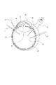
- FIG. 2 schematically shows the cross-sectional structure of the eyeball 30.
- the surface of the eyeball 30 is covered with the cornea 31 and the conjunctiva 32, the iris 34 in which the pupil 33 is formed exists in the back of the cornea 31, and the crystalline lens 35 exists in the back of the iris 34. Further, the retina 36 is present on the entire fundus surface inside the eyeball 30.
- the practitioner 4 inserts the treatment tool 5 into the conjunctiva 32, for example, and performs an operation inside the eyeball 30.
- FIG. 3 schematically shows an example of the configuration of the surgery support device 2.
- the surgery support device 2 includes an endoscope holding device 11, an endoscope 12, an operation unit 13, a calculation / control unit 14, and a monitor 15.
- the endoscope holding device 11 has a base portion 16 and an arm portion 17.
- the base portion 16 is placed on the floor or the like of the operating room, and the arm portion 17 is attached to the base portion 16.
- the arm portion 17 is rotatably supported by the base portion 16.
- the arm portion 17 includes one or more joint portions and rotating portions, and is formed in a mechanism capable of moving the arm tip portion 20 to an arbitrary position.
- FIG. 4 schematically shows an example of the configuration of the arm tip portion 20.
- the arm tip portion 20 has a holder 21 for holding the endoscope 12 and a measuring unit 22 used for measuring the distance of the subject 3 to the cornea 31.
- the holder 21 is formed in a mechanism that allows the endoscope 12 to be attached and detached, and the endoscope 12 is fixed to the holder 21 by attaching the endoscope 12.
- the endoscope 12 can be freely moved to an arbitrary position.
- the practitioner 4 By holding the endoscope 12 inserted into the eyeball 30 of the subject 3 with the holder 21, the practitioner 4 does not need to hold the endoscope 12 by hand. Therefore, the practitioner 4 can perform the operation of the eyeball 30 with both hands.
- the measuring unit 22 has an irradiation unit 23 and an imaging unit 24.
- the irradiation unit 23 is, for example, an LED (Light Emitting Diode), and outputs light that irradiates the eyeball 30 of the subject 3.
- the image pickup unit 24 has image pickup units 24L and 24R so that distance measurement by the so-called stereo method is possible.
- the image pickup units 24L and 24R are arranged at predetermined intervals, for example, in the vicinity of the upper part of the holder 21.
- the optical axes of the image pickup units 24L and 24R are parallel, and the focal lengths are the same.
- the frame periods are synchronized and the frame rates are the same.
- the captured image signals obtained by each of the imaging elements of the imaging units 24L and 24R are A / D (Analog / Digital) converted to be digital image signals (captured image data) representing the luminance value according to a predetermined gradation in pixel units.
- the distance from the image pickup unit 24L, 24R to the cornea 31 of the subject 3 is measured based on the image pickup image signals obtained by each image pickup element of the image pickup unit 24L, 24R obtained in the state where the eyeball 30 is irradiated by the irradiation unit 23. can do.
- the relative positional relationship between the irradiation unit 23 and the imaging units 24L and 24R is fixed. Further, the relative positional relationship between the image pickup units 24L and 24R and the holder 21 described above is fixed. Therefore, by fixing the endoscope 12 to the holder 21, the relative positional relationship between the irradiation unit 23 and the image pickup units 24L and 24R and the endoscope 12 is fixed.
- the endoscope 12 of the surgical support device 2 is inserted into the eyeball 30 in a state of being fixed to the holder 21 (see FIG. 2).
- the state inside the eyeball 30 is imaged by the inserted endoscope 12.
- the captured image signals obtained by the image pickup element of the endoscope 12 are A / D converted, respectively, and are used as digital image signals (captured image data) representing the luminance value according to a predetermined gradation in pixel units.
- the captured image based on the captured image data from the endoscope 12 is displayed on the liquid crystal display of the monitor 15.
- the operation unit 13 comprehensively shows an operation device used for operating the arm unit 17 and rotating an image captured image based on the image captured by the endoscope 12 displayed on the monitor 15.
- the operation unit 13 may be a foot pedal, a remote control device (remote controller) that is manually operated, or the like. Although the foot pedal is shown as an example in FIG. 3, the operation unit 13 is not limited to this as described above. The details of the rotation operation method according to the operation of the operation unit 13 of the captured image by the endoscope 12 will be described later.
- the calculation / control unit 14 performs various processes necessary for realizing the present embodiment, such as operation control of the arm unit 17, generation processing of various images to be displayed on the monitor 15, and display control processing on the monitor 15. Run.
- the calculation / control unit 14 is configured to include, for example, a microcomputer having a CPU (Central Processing Unit), a ROM (Read Only Memory), a RAM (Random Access Memory), and the like.
- the arithmetic / control unit 14 is realized by one or a plurality of microcomputers.
- the calculation / control unit 14 is built in, for example, the base unit 16 of the endoscope holding device 11.
- the arithmetic / control device 14 may be built in another external device.
- the monitor 15 displays the display image 6 on the liquid crystal display based on the display control from the calculation / control unit 14.
- FIG. 5 shows an example of the display image 6 displayed on the monitor 15.
- a display image 6 having an endoscope captured image 61, an eyeball map image 62, an endoscope viewpoint map image 63, an insertion length presentation image 64, and the like is displayed.
- the display image 6 also includes images related to various information as needed.
- the endoscope captured image 61 is an captured image based on the captured image data from the endoscope 12. As the endoscope image captured image 61, for example, the internal state of the eyeball 30 imaged by the endoscope 12 is displayed. The endoscope image 61 can be rotated by an operation by the operation unit 13. The details of the rotation method of the endoscope image 61 will be described later.
- the eyeball map image 62 shows the positional relationship between the eyeball 30 and the endoscope 12.
- the eyeball 30 is displayed by the three-dimensional eyeball model image 30A.
- the position of the endoscope 12 with respect to the eyeball 30 is displayed by the endoscope model image 12A.
- the endoscope viewpoint map image 63 displays an endoscope model image 12B showing the endoscope 12 and a three-dimensional model image 300 of the subject 3 from the viewpoint of the endoscope 12.
- the eyeball model image 30B is displayed on the three-dimensional model image 300.
- the endoscope viewpoint map image 63 rotates in conjunction with the rotation of the endoscope image captured image 61.
- the three-dimensional model image 300 rotates with the position of the endoscope model image 12B showing the endoscope 12 fixed.
- the details of the rotation method of the endoscope viewpoint map image 63 will be described later.
- the insertion length presentation image 64 displays a numerical value of the insertion length of the endoscope 12 with respect to the eyeball 30 and a numerical value of the distance from the endoscope tip portion 120 to the retina 36.
- the practitioner 4 performs an operation on the eyeball 30 while checking the display image 6 displayed on the monitor 15.
- FIG. 6 shows an example of the configuration of the surgery support device 2 as a block diagram.
- the calculation / control unit 14 includes a drive control unit 141, an image processing unit 142, a position determination unit 143, an image generation unit 144, and a display control unit 145.
- the drive control unit 141 controls the operation of the joint portion and the rotating portion of the arm portion 17 of the endoscope holding device 11 based on, for example, an operation signal input from the operation unit 13.
- the drive control unit 141 can move the position of the endoscope 12 fixed to the holder 21 of the arm tip portion 20 by controlling the operation of the arm portion 17. Further, the drive control unit 141 controls the output of the irradiation unit 23 and controls the image pickup of the image pickup unit 24.
- the image processing unit 142 performs various signal processing such as luminance signal processing, color processing, resolution conversion processing, and codec processing on the image signal based on the image captured by the endoscope 12.
- the image processing unit 142 outputs an image signal subjected to various signal processing to the image generation unit 144.
- the position determination unit 143 calculates the image pickup distance, which is the distance from the image pickup unit 24 to the cornea 31, based on the image pickup image signal of the eyeball 30 by each image pickup element of the image pickup units 24L and 24R input from the image pickup unit 24. Further, the position determination unit 143 calculates the relative positional relationship between the eyeball 30 and the endoscope tip portion 120 based on the imaging distance. The position determination unit 143 outputs the determination result (relative positional relationship between the eyeball 30 and the endoscope tip portion 120) to the image generation unit 144.
- the image generation unit 144 generates the display image 6 as shown in FIG. 5 by using various input information from the image processing unit 142, the position determination unit 143, the operation unit 13, and the like. Details of various image generation methods constituting the display image 6 will be described later.
- the image generation unit 144 outputs the image signal of the generated display image 6 to the display control unit 145.
- the display control unit 145 controls to display the display image 6 on the monitor 15 based on the image signal input from the image generation unit 144.
- FIG. 7 is a flowchart showing an example of the processing executed by the calculation / control unit 14.
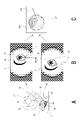
- FIG. 8 shows an outline of a procedure for determining the positional relationship between the eyeball 30 and the endoscope 12.
- step S101 the calculation / control unit 14 performs irradiation start control processing.
- the calculation / control unit 14 causes the irradiation unit 23 to output the light 25 for irradiating the eyeball 30 as shown in FIG. 8A.
- the light 25 output from the irradiation unit 23 is schematically shown by a broken line.
- the irradiation start control process is a process required for determining the positional relationship between the eyeball 30 and the endoscope 12 used for generating the image data of the endoscope viewpoint map image 63 described later.
- step S102 the calculation / control unit 14 stores each frame image data as captured image data obtained by imaging the inside of the eyeball 30 by the endoscope 12 in the internal memory.
- step S103 the calculation / control unit 14 acquires the image rotation angle data.
- the image rotation angle data is information indicating the rotation direction and rotation angle of the captured image data used when performing the rotation processing of the captured image data from the endoscope 12.
- the image rotation angle data is appropriately updated according to the operation input from the operation unit 13. However, the image rotation angle data is not updated when the imaging direction of the endoscope 12 is displaced according to the operation of the arm portion 17.
- the image rotation angle data is the endoscopically captured image. It is a value that indicates the angle of rotation processing of 0 °.
- the calculation / control unit 14 detects an operation input from the operation unit 13, the calculation / control unit 14 updates the image rotation angle data according to the operation amount. For example, the rotation direction is indicated by the positive / negative of the angle of the updated image rotation angle data. The details of the image rotation angle data update process will be described later.
- the calculation / control unit 14 generates the image data of the endoscope image captured image 61 based on the image image data captured from the endoscope 12 and the image rotation angle data. In this case, at least the calculation / control unit 14 generates the image data of the endoscope image captured image 61 in which the image image data captured from the endoscope 12 is rotated in a direction and an angle based on the image rotation angle data.
- the calculation / control unit 14 captures the image captured by the endoscope 12 without rotating it. Image data as an image 61 is generated.
- step S105 the calculation / control unit 14 executes the image generation processing of the eyeball map image 62 and the endoscope viewpoint map image 63.
- This image generation process will be described with reference to FIG.
- FIG. 9 is a flowchart showing an example of the image generation process executed by the calculation / control unit 14.
- step S201 the calculation / control unit 14 stores each frame image data as the captured image data obtained by the imaging units 24L and 24R imaging the eyeball 30 in the internal memory.
- step S202 the calculation / control unit 14 recognizes various images such as recognizing the light spot of the light 25 from the irradiation unit 23 reflected on the eyeball 30 and the cornea 31 of the eyeball 30 based on the two captured image data as each frame. Perform analysis processing.
- step S203 the calculation / control unit 14 shifts the position of the light spot reflected on the cornea 31 with respect to the pair of captured image data (stereo image) obtained by the imaging units 24L and 24R.
- the imaging distance which is the distance from the imaging unit 24 to the cornea 31, is calculated according to the principle of triangulation.
- the calculation / control unit 14 determines the positional relationship between the image pickup unit 24 and the eyeball 30 based on the calculated imaging distance.
- the eyeball model data is used as the data of the size of the eyeball 30.
- the eyeball model data is, for example, three-dimensional data assuming a general human eyeball size. Since the human eyeball size does not differ greatly although there are some individual differences, it is preset as eyeball model data based on the standard human eyeball size.
- the calculation / control unit 14 can calculate (determine) the positional relationship between the image pickup unit 24 and the eyeball 30 by using the image pickup distance and the eyeball model data. It is also possible to measure the eyeball size of the eyeball 30 of the subject 3 in advance for the operation and set the eyeball model data by reflecting the measurement result.
- step S204 the calculation / control unit 14 determines the positional relationship between the endoscope 12 and the eyeball 30 based on the positional relationship between the imaging unit 24 and the eyeball 30.
- the endoscope 12 is fixed to the holder 21 of the arm tip portion 20 so that the relative positional relationship with the imaging unit 24 is fixed. Therefore, in a state where the endoscope 12 is fixed to the holder 21, the position of the endoscope 12 is naturally defined according to the position of the image pickup unit 24. Further, the shape size of the endoscope 12 fixed to the holder 21 up to the endoscope tip portion 120 in the axial direction is known. Therefore, by setting information regarding the shape size of the endoscope 12 in advance, the calculation / control unit 14 can calculate the position of the endoscope tip portion 120 from the specified position of the endoscope 12. can.
- the calculation / control unit 14 can calculate (determine) the positional relationship of the endoscope 12 (endoscope tip portion 120) with respect to the eyeball 30 based on the positional relationship between the eyeball 30 and the imaging unit 24. ..
- the calculation / control unit 14 uses the positional relationship between the determined eyeball 30 and the endoscope 12 (endoscope tip portion 120) as the positional relationship between the three-dimensional eyeball model image 30A and the endoscope model image 12A.
- the image data of the shown eyeball map image 62 is generated (see FIG. 8C).
- step S206 the calculation / control unit 14 generates the image data of the endoscope viewpoint map image 63 as shown in FIG.
- the endoscope viewpoint map image 63 is composed of a three-dimensional model image 300 showing the head of the subject 3 and an endoscope model image 12B showing the endoscope 12.
- the three-dimensional eyeball model image 30B of the eyeball 30 is displayed on the three-dimensional model image 300.
- the value indicating the angle of the head of the subject 3 with respect to the endoscope 12 is the state in which the subject 3 is lying on the operating table 1 on his back, and the endoscope holding device 11 is installed on the operating table 1. It is set in advance as head angle data on the premise that the angle is specified.
- the calculation / control unit 14 generates image data of the three-dimensional model image 300 having the three-dimensional eyeball model image 30B based on the three-dimensional model data and the head angle data.
- the calculation / control unit 14 synthesizes the three-dimensional model image 300 and the endoscope model image 12B based on the positional relationship between the eyeball 30 and the endoscope 12 determined in step S204, so that the endoscope viewpoint map image is obtained.
- Generate 63 image data In the endoscope viewpoint map image 63, an image obtained by observing the head of the three-dimensional model image 300 from the viewpoint of the endoscope 12 is displayed.
- the calculation / control unit 14 generates image data of the endoscope viewpoint map image 63 that has undergone rotation processing based on the image rotation angle data acquired in step S103 of FIG. 7. At this time, the calculation / control unit 14 generates image data obtained by rotating the three-dimensional model image 300 with the position of the endoscope model image 12B fixed as the endoscope viewpoint map image 63.
- the rotation angle of 0 ° is instructed as the image rotation angle data. Therefore, in the calculation / control unit 14, the image data that does not rotate the endoscope viewpoint map image 63 is the endoscope. It is generated as a viewpoint map image 63.
- step S206 the calculation / control unit 14 completes the process of generating the eyeball map image 62 and the endoscope viewpoint map image 63 in S105 of FIG. 7. Subsequently, the calculation / control unit 14 proceeds to the process in step S106.
- step S106 the calculation / control unit 14 generates the image data of the display image 6.
- the calculation / control unit 14 generates a display image 6 by synthesizing an endoscope image captured image 61, an eyeball map image 62, an endoscope viewpoint map image 63, an insertion length presentation image 64, and other necessary images.
- the calculation / control unit 14 obtains information on the insertion length of the endoscope 12 into the eyeball 30 and the endoscope tip portion 120 based on the positional relationship between the determined eyeball 30 and the endoscope 12 (endoscope tip portion 120). And the information about the distance from the subject 3 to the retina 36 is calculated. Then, the calculation / control unit 14 generates the image data of the insertion length presentation image 64 based on the information.
- step S107 the calculation / control unit 14 performs display control for displaying the display image 6 on the liquid crystal display of the monitor 15. As a result, the display image 6 as shown in FIG. 5 is displayed on the same screen of the monitor 15.
- the treatment tool 5 may be reflected in the endoscope image captured image 61 as shown in FIG.
- the endoscopic image 61 does not match the direction in which the practitioner 4 shown in FIG. 1 performs the operation inside the eyeball 30 in the vertical and horizontal directions.
- the practitioner 4 needs to rotate the endoscope image 61 to a position where it is easy to see (for example, the position shown in FIG. 11) by operating the operation unit 13 in order to smoothly proceed the operation. Therefore, the calculation / control unit 14 performs the processes of steps S108 and S109 in FIG.
- step S108 the calculation / control unit 14 determines whether or not an operation input from the operation unit 13 has been detected.
- the operation input is performed, for example, by the practitioner 4 operating the foot pedal with his / her foot.
- step S108 the calculation / control unit 14 returns the process to step S102, and then executes the same process. That is, in the initial state, the endoscope image captured image 61 and the endoscope viewpoint map image 63 in a non-rotating state are displayed on the monitor 15.
- step S108 when the operation input is detected in step S108, the calculation / control unit 14 proceeds from step S108 to S109.
- step S109 the calculation / control unit 14 updates the image rotation angle data.
- the calculation / control unit 14 updates the rotation direction and the rotation angle as image rotation angle data based on the operation input from the operation unit 13.
- step S109 the calculation / control unit 14 returns the processing to step S102. Then, the calculation / control unit 14 performs the processes of steps S102 to S104, and rotates the image data captured by the endoscope 12 based on the updated image rotation angle data to obtain the image data of the endoscope image 61. Generate.
- the endoscope imaging displayed on the monitor 15 is performed according to the operation of the operation unit 13 without causing the positional displacement of the endoscope 12 inside the eyeball 30.
- the image 61 can continue to rotate.
- the endoscope image 61 can be rotated from the position shown in FIG. 10 to the position shown in FIG.
- the calculation / control unit 14 fixes the position of the endoscope model image 12B and makes a three-dimensional model based on the updated image rotation angle data.
- the image data of the endoscope viewpoint map image 63 in which the image 300 is rotated is generated.
- the three-dimensional model image 300 rotates with reference to the fixed endoscope model image 12B.
- the three-dimensional model image 300 is moved from the position shown in FIG. 10 with respect to the endoscope model image 12B. Rotate to the position shown in FIG.
- the image data of the endoscope viewpoint map image 63 rotated in conjunction with the rotation of the endoscope image captured image 61 is generated. Can be done.
- step S106 the calculation / control unit 14 generates image data of the display image 6 including the rotated endoscope image captured image 61 and the endoscope viewpoint map image 63.
- step S107 the calculation / control unit 14 performs display control for displaying the display image 6 on the liquid crystal display of the monitor 15.
- the endoscope image captured image 61 rotated according to the operation of the operation unit 13 of the practitioner 4 is displayed on the monitor 15. Further, the endoscope viewpoint map image 63 rotated in conjunction with the rotation of the endoscope captured image 61 is displayed on the monitor 15.
- the positional relationship between the eyeball 30 and the endoscope 12 (for example, the insertion state of the endoscope 12 with respect to the eyeball 30 (imaging direction)) is spatially determined from the image of the endoscope image 61. It may be difficult to grasp. In such a case, by checking the endoscope viewpoint map image 63 that is rotated in conjunction with the rotation of the endoscope image captured image 61, it is possible to easily grasp the insertion state of the endoscope 12 with respect to the eyeball 30. can.
- the processes from steps S102 to S109 are continuously executed by the calculation / control unit 14.
- the practitioner 4 continues the operation of the operation unit 13 until, for example, the treatment tool 5 reflected in the endoscope image 61 is in a position where surgery can be easily performed, and rotates the endoscope image 61.
- the calculation / control unit 14 determines that the operation input is not detected in step S108. In this case, the calculation / control unit 14 returns the process from step S108 to S102, and then repeatedly executes the process from step S102 to S108 until the operation input is detected in step S108.
- the calculation / control unit 14 generates image data of the endoscope image captured image 61 and the endoscope viewpoint map image 63 based on the last updated image rotation angle data, and controls the display on the monitor 15. ..
- the endoscope image captured image 61 and the endoscope viewpoint map image 63 are displayed on the monitor 15 in a state where the rotation angle at the time of stopping the rotation is maintained.
- the image rotation angle data is updated by the calculation / control unit 14. Will not be done.
- the endoscope-captured image 61 in which only the imaging direction is displaced is displayed on the monitor 15 in a state where the rotation based on the last updated image rotation angle data is maintained. Therefore, the practitioner 4 does not need to rotate the endoscope image captured image 61 again by the operation of the operation unit 13 when the image pickup direction of the endoscope 12 is displaced.
- the endoscope viewpoint map image 63 the state linked to the rotational state of the endoscope image captured image 61 is maintained.
- the imaging direction of the endoscope 12 is displaced, the position of the three-dimensional model image 300 with respect to the endoscope model image 12B in the endoscope viewpoint map image 63 is displaced.
- step S108 When the operation input is detected again in step S108 while the processes of steps S102 to S108 are repeatedly executed, the calculation / control unit 14 proceeds with the processes in the order of steps S109 and S102, and then executes the same process.
- the surgical support device 2 has a holder 21 for holding the endoscope 12, and an arm for adjusting the position of the endoscope 12 while the endoscope 12 is held by the holder 21.
- the image generation unit 144 that generates the endoscope viewpoint map image 63 on which the three-dimensional model image 300 of the subject 3 from the viewpoint of the endoscope 12 held in the holder 21 is displayed, and the endoscope.
- a display control unit 145 that controls the display of the viewpoint map image 63 and the endoscope image captured image 61 captured by the endoscope 12 and an operation unit 13 for rotating the endoscope image captured image 61 are provided and operated.
- the endoscope image captured image 61 displayed without causing the positional displacement of the endoscope 12 is rotated, and the endoscope viewpoint map image 63 is rotated in conjunction with the rotation. (See FIGS. 7 and 8).
- the endoscope viewpoint map image 63 showing the positional relationship between the endoscope 12 and the subject 3 corresponding to the state of the endoscope image captured image 61 after rotation is displayed. Therefore, the practitioner 4 can spatially grasp the insertion state of the endoscope 12 with respect to the eyeball 30 of the subject 3. Therefore, the practitioner 4 can perform an operation in which the positional relationship is intuitively grasped even in a state where the endoscope image 61 is rotated, and the operation on the eyeball 30 can proceed smoothly. Further, since the position of the endoscope 12 can be grasped, it is possible to prevent the practitioner 4 from coming into contact with the endoscope 12 or the like.
- the rotation of the endoscope viewpoint map image 63 is performed in a state where the position of the image showing the endoscope 12 is fixed (S105 in FIG. 7, S205 in FIG. 9, See FIGS. 10, 11 and the like).
- the endoscope viewpoint map image 63 is always displayed in a state where the image showing the endoscope 12 is reflected regardless of the rotational state of the endoscope image captured image 61. Therefore, by visually recognizing the endoscope viewpoint map image 63, it is possible to always confirm the insertion state of the endoscope 12 into the eyeball 30 of the subject 3 regardless of the rotation of the endoscope image captured image 61. Therefore, the surgery on the eyeball 30 can proceed smoothly.
- the display control unit 145 displays the endoscope viewpoint map image 63 and the endoscope image captured image 61 on the same screen (see S107 and the like in FIGS. 5 and 7). ..
- the endoscope viewpoint map image 63 can be confirmed without shifting the line of sight to another monitor 15. Therefore, the visibility of the endoscope viewpoint map image 63 is improved, and the operation on the eyeball 30 can proceed smoothly.
- the display control unit 145 displays the eyeball map image 62 showing the position of the endoscope 12 on the three-dimensional eyeball model and the endoscope viewpoint map image 63 on the same screen. Display (see S107 and the like in FIGS. 5 and 7).
- the eyeball map image 62 can be confirmed without shifting the line of sight to another monitor 15. Therefore, since a plurality of information can be confirmed simultaneously on one monitor 15, the operation on the eyeball 30 can proceed smoothly.
- the example of the endoscope is described as an example of the endoscope 12, but the endoscope 12 is not limited to the endoscope.
- various endoscopes can be applied, such as a thoracoscope incising and inserting between the ribs of the subject 3 and a laparoscope incising and inserting the abdomen.
- the embodiments described in the present disclosure are merely examples, and the present invention is not limited to the above-described embodiments. Moreover, not all of the combinations of configurations described in the embodiments are essential for solving the problem. Further, the effects described in the present disclosure are merely exemplary and not limited, and may have other effects, or may play a part of the effects described in the present disclosure. good.
Landscapes
- Health & Medical Sciences (AREA)
- Life Sciences & Earth Sciences (AREA)
- Surgery (AREA)
- Engineering & Computer Science (AREA)
- General Health & Medical Sciences (AREA)
- Animal Behavior & Ethology (AREA)
- Biomedical Technology (AREA)
- Heart & Thoracic Surgery (AREA)
- Veterinary Medicine (AREA)
- Public Health (AREA)
- Physics & Mathematics (AREA)
- Molecular Biology (AREA)
- Medical Informatics (AREA)
- Nuclear Medicine, Radiotherapy & Molecular Imaging (AREA)
- Pathology (AREA)
- Biophysics (AREA)
- Optics & Photonics (AREA)
- Radiology & Medical Imaging (AREA)
- Ophthalmology & Optometry (AREA)
- Signal Processing (AREA)
- General Physics & Mathematics (AREA)
- Theoretical Computer Science (AREA)
- Oral & Maxillofacial Surgery (AREA)
- Vascular Medicine (AREA)
- Endoscopes (AREA)
- Image Processing (AREA)
Abstract
Afin d'obtenir un affichage qui permet d'acquérir spatialement l'état d'un endoscope inséré dans un sujet, la présente invention comprend : une partie de bras qui comporte un support pour maintenir l'endoscope, la partie de bras ajustant la position de l'endoscope tandis que l'endoscope est maintenu par le support ; un générateur d'images pour générer une image de carte de point d'observation d'endoscope, qui est une image d'un modèle tridimensionnel du sujet depuis le point d'observation de l'endoscope maintenu par le support ; une unité de commande d'affichage pour effectuer une commande d'affichage de l'image de carte de point d'observation d'endoscope et une image de capture d'endoscope capturée par l'endoscope ; et une unité d'actionnement pour mettre en rotation l'image de capture d'endoscope. L'image de capture d'endoscope affichée est mise en rotation sans causer un déplacement de position de l'endoscope en réponse à une opération effectuée au moyen de l'unité d'actionnement, et l'image de carte de point d'observation d'endoscope est mise en rotation en coordination avec ladite rotation.
Priority Applications (5)
| Application Number | Priority Date | Filing Date | Title |
|---|---|---|---|
| CN202080101148.8A CN115697178B (zh) | 2020-10-27 | 2020-10-27 | 手术支援装置 |
| EP20959728.5A EP4179954A4 (fr) | 2020-10-27 | 2020-10-27 | Dispositif d'aide à la chirurgie |
| JP2021558994A JP6993043B1 (ja) | 2020-10-27 | 2020-10-27 | 手術支援装置 |
| PCT/JP2020/040231 WO2022091210A1 (fr) | 2020-10-27 | 2020-10-27 | Dispositif d'aide à la chirurgie |
| US18/306,424 US20230255452A1 (en) | 2020-10-27 | 2023-04-25 | Surgery assisting device |
Applications Claiming Priority (1)
| Application Number | Priority Date | Filing Date | Title |
|---|---|---|---|
| PCT/JP2020/040231 WO2022091210A1 (fr) | 2020-10-27 | 2020-10-27 | Dispositif d'aide à la chirurgie |
Related Child Applications (1)
| Application Number | Title | Priority Date | Filing Date |
|---|---|---|---|
| US18/306,424 Continuation US20230255452A1 (en) | 2020-10-27 | 2023-04-25 | Surgery assisting device |
Publications (1)
| Publication Number | Publication Date |
|---|---|
| WO2022091210A1 true WO2022091210A1 (fr) | 2022-05-05 |
Family
ID=80213773
Family Applications (1)
| Application Number | Title | Priority Date | Filing Date |
|---|---|---|---|
| PCT/JP2020/040231 WO2022091210A1 (fr) | 2020-10-27 | 2020-10-27 | Dispositif d'aide à la chirurgie |
Country Status (5)
| Country | Link |
|---|---|
| US (1) | US20230255452A1 (fr) |
| EP (1) | EP4179954A4 (fr) |
| JP (1) | JP6993043B1 (fr) |
| CN (1) | CN115697178B (fr) |
| WO (1) | WO2022091210A1 (fr) |
Citations (4)
| Publication number | Priority date | Publication date | Assignee | Title |
|---|---|---|---|---|
| JPH11309A (ja) * | 1997-06-12 | 1999-01-06 | Hitachi Ltd | 画像処理装置 |
| JP2008262555A (ja) * | 2007-03-20 | 2008-10-30 | National Univ Corp Shizuoka Univ | 形状情報処理方法、形状情報処理装置及び形状情報処理プログラム |
| WO2017169823A1 (fr) * | 2016-03-30 | 2017-10-05 | ソニー株式会社 | Dispositif et procédé de traitement d'image, système de chirurgie et élément chirurgical |
| WO2018088107A1 (fr) * | 2016-11-10 | 2018-05-17 | ソニー株式会社 | Dispositif de commande pour système d'endoscope et procédé de commande pour système d'endoscope |
Family Cites Families (14)
| Publication number | Priority date | Publication date | Assignee | Title |
|---|---|---|---|---|
| US7037258B2 (en) * | 1999-09-24 | 2006-05-02 | Karl Storz Imaging, Inc. | Image orientation for endoscopic video displays |
| JP4472085B2 (ja) * | 2000-01-26 | 2010-06-02 | オリンパス株式会社 | 手術用ナビゲーションシステム |
| JP2004105539A (ja) * | 2002-09-19 | 2004-04-08 | Hitachi Ltd | カメラを用いた手術システムにおける画像表示方法および手術支援装置 |
| CN1798988B (zh) * | 2003-06-03 | 2010-11-24 | 皇家飞利浦电子股份有限公司 | 使转动的三维超声显示与振动的物体同步 |
| JP4868959B2 (ja) * | 2006-06-29 | 2012-02-01 | オリンパスメディカルシステムズ株式会社 | 体腔内プローブ装置 |
| JP6242569B2 (ja) * | 2011-08-25 | 2017-12-06 | 東芝メディカルシステムズ株式会社 | 医用画像表示装置及びx線診断装置 |
| CN202723822U (zh) * | 2012-08-30 | 2013-02-13 | 三维医疗科技江苏股份有限公司 | 一种光电一体化三维立体阴道镜 |
| CN102999902B (zh) * | 2012-11-13 | 2016-12-21 | 上海交通大学医学院附属瑞金医院 | 基于ct配准结果的光学导航定位导航方法 |
| WO2018230099A1 (fr) * | 2017-06-15 | 2018-12-20 | オリンパス株式会社 | Système d'endoscope et procédé d'actionnement de système d'endoscope |
| CN108542351A (zh) * | 2018-01-26 | 2018-09-18 | 徐州云联医疗科技有限公司 | 一种医学影像断层图像与三维解剖图像的同步显示系统 |
| US20210121264A1 (en) * | 2018-05-02 | 2021-04-29 | Riverfield Inc. | Intraocular surgery instrument holder |
| CN111000631B (zh) * | 2019-12-17 | 2021-04-06 | 上海嘉奥信息科技发展有限公司 | 基于Unity3D体渲染的内窥镜模拟方法及系统 |
| CN111281540B (zh) * | 2020-03-09 | 2021-06-04 | 北京航空航天大学 | 基于虚实融合的骨科微创术中实时可视化导航系统 |
| CN111466952B (zh) * | 2020-04-26 | 2023-03-31 | 首都医科大学附属北京朝阳医院 | 一种超声内镜与ct三维图像实时转化方法和系统 |
-
2020
- 2020-10-27 JP JP2021558994A patent/JP6993043B1/ja active Active
- 2020-10-27 WO PCT/JP2020/040231 patent/WO2022091210A1/fr unknown
- 2020-10-27 EP EP20959728.5A patent/EP4179954A4/fr active Pending
- 2020-10-27 CN CN202080101148.8A patent/CN115697178B/zh active Active
-
2023
- 2023-04-25 US US18/306,424 patent/US20230255452A1/en active Pending
Patent Citations (4)
| Publication number | Priority date | Publication date | Assignee | Title |
|---|---|---|---|---|
| JPH11309A (ja) * | 1997-06-12 | 1999-01-06 | Hitachi Ltd | 画像処理装置 |
| JP2008262555A (ja) * | 2007-03-20 | 2008-10-30 | National Univ Corp Shizuoka Univ | 形状情報処理方法、形状情報処理装置及び形状情報処理プログラム |
| WO2017169823A1 (fr) * | 2016-03-30 | 2017-10-05 | ソニー株式会社 | Dispositif et procédé de traitement d'image, système de chirurgie et élément chirurgical |
| WO2018088107A1 (fr) * | 2016-11-10 | 2018-05-17 | ソニー株式会社 | Dispositif de commande pour système d'endoscope et procédé de commande pour système d'endoscope |
Non-Patent Citations (1)
| Title |
|---|
| See also references of EP4179954A4 * |
Also Published As
| Publication number | Publication date |
|---|---|
| EP4179954A1 (fr) | 2023-05-17 |
| EP4179954A4 (fr) | 2023-08-30 |
| US20230255452A1 (en) | 2023-08-17 |
| JPWO2022091210A1 (fr) | 2022-05-05 |
| CN115697178B (zh) | 2024-05-10 |
| JP6993043B1 (ja) | 2022-01-13 |
| CN115697178A (zh) | 2023-02-03 |
Similar Documents
| Publication | Publication Date | Title |
|---|---|---|
| JP6891244B2 (ja) | 視線追跡を使用する医療装置、システム、及び方法 | |
| WO2020045015A1 (fr) | Système médical, dispositif de traitement d'informations et méthode de traitement d'informations | |
| WO2018088113A1 (fr) | Actionneur d'entraînement d'articulation et système médical | |
| US20230310098A1 (en) | Surgery assistance device | |
| JP6819223B2 (ja) | 眼科情報処理装置、眼科情報処理プログラム、および眼科手術システム | |
| JPWO2018179681A1 (ja) | 医療用観察装置及び観察視野補正方法 | |
| JP7390793B2 (ja) | 眼科装置 | |
| JP6993043B1 (ja) | 手術支援装置 | |
| KR102169674B1 (ko) | 혼합 현실 안저카메라 | |
| JP7029216B1 (ja) | 手術支援装置 | |
| US20230222740A1 (en) | Medical image processing system, surgical image control device, and surgical image control method | |
| JP2021003530A (ja) | 医療用観察システム、制御装置及び制御方法 | |
| US20190154953A1 (en) | Control apparatus, control system, and control method | |
| WO2020203225A1 (fr) | Système médical, dispositif et procédé de traitement d'informations | |
| JP7322357B2 (ja) | 眼科装置及び眼科システム | |
| WO2020045014A1 (fr) | Système médical, dispositif de traitement d'informations et procédé de traitement d'informations | |
| JP7377331B2 (ja) | 眼科装置 | |
| JP7216562B2 (ja) | 眼科装置 | |
| WO2022201933A1 (fr) | Système d'observation intravitréenne, système d'observation, procédé d'observation intravitréenne et dispositif d'observation intravitréenne | |
| JP7166080B2 (ja) | 眼科装置 | |
| JP2023142781A (ja) | 眼科システム |
Legal Events
| Date | Code | Title | Description |
|---|---|---|---|
| ENP | Entry into the national phase |
Ref document number: 2021558994 Country of ref document: JP Kind code of ref document: A |
|
| 121 | Ep: the epo has been informed by wipo that ep was designated in this application |
Ref document number: 20959728 Country of ref document: EP Kind code of ref document: A1 |
|
| ENP | Entry into the national phase |
Ref document number: 2020959728 Country of ref document: EP Effective date: 20230209 |
|
| NENP | Non-entry into the national phase |
Ref country code: DE |