WO2022085548A1 - アルミニウム部材及びその製造方法 - Google Patents
アルミニウム部材及びその製造方法 Download PDFInfo
- Publication number
- WO2022085548A1 WO2022085548A1 PCT/JP2021/037995 JP2021037995W WO2022085548A1 WO 2022085548 A1 WO2022085548 A1 WO 2022085548A1 JP 2021037995 W JP2021037995 W JP 2021037995W WO 2022085548 A1 WO2022085548 A1 WO 2022085548A1
- Authority
- WO
- WIPO (PCT)
- Prior art keywords
- aluminum member
- porous layer
- aluminum
- base material
- electrolytic solution
- Prior art date
- Legal status (The legal status is an assumption and is not a legal conclusion. Google has not performed a legal analysis and makes no representation as to the accuracy of the status listed.)
- Ceased
Links
Images








Classifications
-
- C—CHEMISTRY; METALLURGY
- C25—ELECTROLYTIC OR ELECTROPHORETIC PROCESSES; APPARATUS THEREFOR
- C25D—PROCESSES FOR THE ELECTROLYTIC OR ELECTROPHORETIC PRODUCTION OF COATINGS; ELECTROFORMING; APPARATUS THEREFOR
- C25D11/00—Electrolytic coating by surface reaction, i.e. forming conversion layers
- C25D11/02—Anodisation
- C25D11/04—Anodisation of aluminium or alloys based thereon
- C25D11/06—Anodisation of aluminium or alloys based thereon characterised by the electrolytes used
- C25D11/08—Anodisation of aluminium or alloys based thereon characterised by the electrolytes used containing inorganic acids
-
- C—CHEMISTRY; METALLURGY
- C25—ELECTROLYTIC OR ELECTROPHORETIC PROCESSES; APPARATUS THEREFOR
- C25D—PROCESSES FOR THE ELECTROLYTIC OR ELECTROPHORETIC PRODUCTION OF COATINGS; ELECTROFORMING; APPARATUS THEREFOR
- C25D11/00—Electrolytic coating by surface reaction, i.e. forming conversion layers
- C25D11/02—Anodisation
- C25D11/04—Anodisation of aluminium or alloys based thereon
-
- C—CHEMISTRY; METALLURGY
- C21—METALLURGY OF IRON
- C21D—MODIFYING THE PHYSICAL STRUCTURE OF FERROUS METALS; GENERAL DEVICES FOR HEAT TREATMENT OF FERROUS OR NON-FERROUS METALS OR ALLOYS; MAKING METAL MALLEABLE, e.g. BY DECARBURISATION OR TEMPERING
- C21D8/00—Modifying the physical properties of ferrous metals or ferrous alloys by deformation combined with, or followed by, heat treatment
- C21D8/02—Modifying the physical properties of ferrous metals or ferrous alloys by deformation combined with, or followed by, heat treatment during manufacturing of plates or strips
- C21D8/0278—Modifying the physical properties of ferrous metals or ferrous alloys by deformation combined with, or followed by, heat treatment during manufacturing of plates or strips involving a particular surface treatment
-
- C—CHEMISTRY; METALLURGY
- C22—METALLURGY; FERROUS OR NON-FERROUS ALLOYS; TREATMENT OF ALLOYS OR NON-FERROUS METALS
- C22C—ALLOYS
- C22C21/00—Alloys based on aluminium
-
- C—CHEMISTRY; METALLURGY
- C25—ELECTROLYTIC OR ELECTROPHORETIC PROCESSES; APPARATUS THEREFOR
- C25D—PROCESSES FOR THE ELECTROLYTIC OR ELECTROPHORETIC PRODUCTION OF COATINGS; ELECTROFORMING; APPARATUS THEREFOR
- C25D11/00—Electrolytic coating by surface reaction, i.e. forming conversion layers
- C25D11/02—Anodisation
- C25D11/04—Anodisation of aluminium or alloys based thereon
- C25D11/06—Anodisation of aluminium or alloys based thereon characterised by the electrolytes used
- C25D11/10—Anodisation of aluminium or alloys based thereon characterised by the electrolytes used containing organic acids
-
- C—CHEMISTRY; METALLURGY
- C25—ELECTROLYTIC OR ELECTROPHORETIC PROCESSES; APPARATUS THEREFOR
- C25D—PROCESSES FOR THE ELECTROLYTIC OR ELECTROPHORETIC PRODUCTION OF COATINGS; ELECTROFORMING; APPARATUS THEREFOR
- C25D11/00—Electrolytic coating by surface reaction, i.e. forming conversion layers
- C25D11/02—Anodisation
- C25D11/04—Anodisation of aluminium or alloys based thereon
- C25D11/12—Anodising more than once, e.g. in different baths
-
- C—CHEMISTRY; METALLURGY
- C25—ELECTROLYTIC OR ELECTROPHORETIC PROCESSES; APPARATUS THEREFOR
- C25D—PROCESSES FOR THE ELECTROLYTIC OR ELECTROPHORETIC PRODUCTION OF COATINGS; ELECTROFORMING; APPARATUS THEREFOR
- C25D11/00—Electrolytic coating by surface reaction, i.e. forming conversion layers
- C25D11/02—Anodisation
- C25D11/04—Anodisation of aluminium or alloys based thereon
- C25D11/14—Producing integrally coloured layers
-
- C—CHEMISTRY; METALLURGY
- C25—ELECTROLYTIC OR ELECTROPHORETIC PROCESSES; APPARATUS THEREFOR
- C25D—PROCESSES FOR THE ELECTROLYTIC OR ELECTROPHORETIC PRODUCTION OF COATINGS; ELECTROFORMING; APPARATUS THEREFOR
- C25D11/00—Electrolytic coating by surface reaction, i.e. forming conversion layers
- C25D11/02—Anodisation
- C25D11/04—Anodisation of aluminium or alloys based thereon
- C25D11/16—Pretreatment, e.g. desmutting
-
- C—CHEMISTRY; METALLURGY
- C25—ELECTROLYTIC OR ELECTROPHORETIC PROCESSES; APPARATUS THEREFOR
- C25D—PROCESSES FOR THE ELECTROLYTIC OR ELECTROPHORETIC PRODUCTION OF COATINGS; ELECTROFORMING; APPARATUS THEREFOR
- C25D11/00—Electrolytic coating by surface reaction, i.e. forming conversion layers
- C25D11/02—Anodisation
- C25D11/04—Anodisation of aluminium or alloys based thereon
- C25D11/18—After-treatment, e.g. pore-sealing
- C25D11/24—Chemical after-treatment
Definitions
- This disclosure relates to aluminum members and their manufacturing methods.
- the arithmetic average height Sa of the surface of the base material is 0.1 ⁇ m to 0.5 ⁇ m
- the maximum height Sz is 0.2 ⁇ m to 5 ⁇ m
- the average length RSm of the roughness curve element is defined.
- Aluminum members having a size of 0.5 ⁇ m to 10 ⁇ m are disclosed.
- the aluminum member having a white appearance is obtained by setting the arithmetic average height Sa, the maximum height Sz, and the average length RSm of the roughness curve element of the base material within a predetermined range. Is obtained.
- an aluminum member that improves the whiteness when viewed from an angle and has an appearance similar to that of paper is obtained.
- An object of the present disclosure is to provide an aluminum member having a white color and low angle dependence and a method for manufacturing the same.
- the aluminum member according to the first aspect of the present disclosure includes a base material formed of aluminum or an aluminum alloy.
- the aluminum member is in contact with the barrier layer in contact with the surface of the base material, the first porous layer in contact with the surface of the barrier layer opposite to the base material, and the first porous layer in contact with the surface opposite to the barrier layer. It comprises an anodic oxide film comprising a second porous layer having a plurality of holes aligned linearly extending from a surface in contact with the porous layer toward an exposed surface.
- the first porous layer has at least one of a plurality of branched holes and a plurality of holes having an average pore diameter larger than that of the second porous layer.
- a base material formed of aluminum or an aluminum alloy is first anodized with an electrolytic solution capable of forming a plurality of aligned and linearly extending pores. Includes a first anodizing step.
- the above method includes a second anodizing step of second anodizing the first anodized substrate with an electrolytic solution.
- the second anodizing electrolytic solution is an electrolytic solution capable of forming at least one of a plurality of branched holes and a plurality of holes having an average pore diameter larger than the plurality of linearly extending holes.
- an aluminum member having a white color and low angle dependence and a method for manufacturing the same.
- FIG. 1 is a cross-sectional view showing an example of an aluminum member according to the present embodiment.
- FIG. 2 is a diagram showing an example of a method for manufacturing an aluminum member according to the present embodiment.
- FIG. 3 is a diagram illustrating a method of evaluating the angle dependence of whiteness using a goniometer.
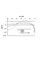
- FIG. 4 is a graph showing the angle dependence of Example 1, Comparative Example 1, and Reference Example (copy paper).
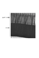
- FIG. 5 is an image obtained by processing a cross section of the aluminum member of Example 12 by FIB (focused ion beam) and magnifying it 2,550 times with a TEM (transmission electron microscope).
- FIG. 1 is a cross-sectional view showing an example of an aluminum member according to the present embodiment.
- FIG. 2 is a diagram showing an example of a method for manufacturing an aluminum member according to the present embodiment.
- FIG. 3 is a diagram illustrating a method of evaluating the angle dependence of whiteness using a goniometer.
- FIG. 4 is a graph showing
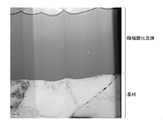
- FIG. 6 is an image in which a cross section of the aluminum member of Example 12 is processed by FIB (focused ion beam) and magnified 19,500 times by a TEM (transmission electron microscope).
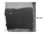
- FIG. 7 is an image of the cross section of the aluminum member of Example 12 processed by FIB (focused ion beam) and magnified 43,000 times by TEM (transmission electron microscope).
- FIG. 8 is an image in which the cross section of the aluminum member of Comparative Example 6 is processed by FIB (focused ion beam) and magnified 2,550 times by a TEM (transmission electron microscope).
- FIG. 9 is an image in which the cross section of the aluminum member of Comparative Example 6 is processed by FIB (focused ion beam) and magnified 19,500 times by TEM (transmission electron microscope).
- FIG. 7 is an image of the cross section of the aluminum member of Example 12 processed by FIB (focused ion beam) and magnified 43,000 times by TEM (transmission electron microscope).
- FIG. 8 is an image in which the
- FIG. 10 is an image in which the cross section of the aluminum member of Comparative Example 6 is processed by FIB (focused ion beam) and magnified 43,000 times by TEM (transmission electron microscope).
- FIG. 11 is an image in which the cross section of the aluminum member of Comparative Example 7 is processed by FIB (focused ion beam) and magnified 2,550 times by a TEM (transmission electron microscope).
- FIG. 12 is an image in which the cross section of the aluminum member of Comparative Example 7 is processed by FIB (focused ion beam) and magnified 19,500 times by TEM (transmission electron microscope).
- FIG. 13 is an image in which the cross section of the aluminum member of Comparative Example 7 is processed by FIB (focused ion beam) and magnified 43,000 times by TEM (transmission electron microscope).
- the aluminum member 1 of the present embodiment includes a base material 10 and an anodic oxide film 20. In the following, these components will be described.
- the base material 10 is formed of aluminum or an aluminum alloy.
- the base material 10 may be formed of, for example, a 1000 series alloy, a 3000 series alloy, a 5000 series alloy, a 6000 series alloy, or a 7000 series alloy.
- the base material 10 contains 0% by mass to 10% by mass of magnesium, 0.1% by mass or less of iron, and 0.1% by mass or less of silicon, and the balance is aluminum and aluminum or aluminum which is an unavoidable impurity. It may be formed of an alloy.
- the base material 10 contains 0% by mass to 10% by mass of magnesium, 0.1% by mass or less of iron, 0.1% by mass or less of silicon, and 10% by mass or less of zinc, and the balance is aluminum. And may be formed of aluminum or an aluminum alloy which is an unavoidable impurity.
- Magnesium does not necessarily have to be contained in the base material 10, but if the base material 10 contains magnesium, aluminum and magnesium can be solid-solved to improve the strength of the base material 10. Further, by setting the magnesium content to 10% by mass or less, it is possible to improve the strength of the base material 10 while suppressing the deterioration of the corrosion resistance of the base material 10.
- the magnesium content is preferably 0.5% by mass or more, and more preferably 1% by mass or more.
- the magnesium content is preferably 8% by mass or less, and more preferably 5% by mass or less.
- the base material 10 preferably contains 0.05% by mass or less of iron. Further, the base material 10 preferably contains 0.05% by mass or less of silicon.
- Zinc does not necessarily have to be contained in the base material 10, but if the base material 10 contains zinc, the strength of the base material 10 can be maintained. Further, by setting the zinc content to 10% by mass or less, the appearance of the aluminum member 1 is not impaired while maintaining the strength of the base material 10.
- the zinc content is preferably 8% by mass or less.
- the base material 10 may contain unavoidable impurities.
- the unavoidable impurities mean those that are present in the raw material or are inevitably mixed in the manufacturing process. Although unavoidable impurities are originally unnecessary, they are acceptable impurities because they are in trace amounts and do not affect the properties of aluminum or aluminum alloys.
- Inevitable impurities that may be contained in aluminum or aluminum alloys are elements other than aluminum, magnesium, iron, and silicon.
- Inevitable impurities that may be contained in aluminum or aluminum alloys include, for example, copper, manganese, chromium, zinc, titanium, gallium, boron, vanadium, zirconium, lead, calcium and cobalt.
- the total amount of unavoidable impurities in the aluminum or aluminum alloy is preferably 0.5% by mass or less, more preferably 0.2% by mass or less, further preferably 0.15% by mass or less, and 0. .10% by mass or less is particularly preferable. Further, the content of each element contained as an unavoidable impurity is preferably 0.05% by mass or less, more preferably 0.03% by mass or less, and further preferably 0.01% by mass or less. preferable.
- the base material 10 may have irregularities on the surface 11 on the anodic oxide film 20 side.
- the aluminum member 1 can diffusely reflect the light transmitted through the anodic oxide film 20 due to the unevenness formed on the surface 11.
- the unevenness of the surface 11 can be formed by a roughening treatment described later.
- the arithmetic average height Sa of the surface 11 of the base material 10 is 0.1 ⁇ m to 0.5 ⁇ m, the maximum height Sz is 0.2 ⁇ m to 5 ⁇ m, and the average length RSm of the roughness curve element is 0.5 ⁇ m to 0.5 ⁇ m. It is preferably 10 ⁇ m.
- the arithmetic average height Sa By setting the arithmetic average height Sa to 0.1 ⁇ m or more, the light transmitted through the anodic oxide film 20 is diffusely reflected on the surface 11 of the base material 10, so that the whiteness when the aluminum member 1 is viewed from an angle is further increased. Can be high. Further, by setting the arithmetic average height Sa to 0.5 ⁇ m or less, it is possible to suppress the light transmitted through the anodic oxide film 20 from being captured between the irregularities of the surface 11 of the base material 10, so that the aluminum member can be used. It is possible to prevent the appearance of 1 from becoming gray.
- the arithmetic mean height Sa is more preferably 0.4 ⁇ m or less. The arithmetic mean height Sa can be measured according to ISO25178.
- the maximum height Sz By setting the maximum height Sz to 0.2 ⁇ m or more, the light transmitted through the anodic oxide film 20 is diffusely reflected on the surface 11 of the base material 10, so that the whiteness when the aluminum member 1 is viewed from an angle is further increased. can do. Further, by setting the maximum height Sz to 5 ⁇ m or less, it is possible to suppress the light transmitted through the anodic oxide film 20 from being captured between the irregularities of the surface 11 of the base material 10, so that the appearance of the aluminum member 1 Can be suppressed from becoming gray.
- the maximum height Sz is more preferably 1 ⁇ m or more, and more preferably 4.7 ⁇ m or less. The maximum height Sz can be measured according to ISO25178.
- the average length RSm of the roughness curve element By setting the average length RSm of the roughness curve element to 0.5 ⁇ m or more, the pitch of the unevenness of the surface 11 of the base material 10 does not become too small, so that the light transmitted through the anodic oxide film 20 is the surface of the base material 10. It is possible to suppress the trapping between the unevenness of 11. Therefore, it is possible to prevent the appearance of the aluminum member 1 from becoming gray. Further, by setting the average length RSm of the roughness curve element to 10 ⁇ m or less, the pitch of the unevenness of the surface 11 of the base material 10 does not become too large. Therefore, the light transmitted through the anodic oxide film 20 is diffusely reflected on the surface 11 of the base material 10, and the whiteness when the aluminum member 1 is viewed from an angle can be further increased.
- the average length RSm of the roughness curve element is more preferably 5 ⁇ m or more, and more preferably 9.5 ⁇ m or less.
- the average length RSm of the roughness curve element can be measured according to JIS B0601: 2013 (ISO 4287: 1997, Amd. 1: 2009).
- the arithmetic average height Sa, maximum height Sz, and average length RSm of the roughness curve element of the surface 11 of the base material 10 can be measured by removing the anodic oxide film 20 from the base material 10. Since the unevenness of the surface 11 of the base material 10 is smoothed by anodization, the shape of the unevenness of the surface 11 of the base material 10 before anodization is different from the unevenness of the surface 11 of the base material 10 after anodization. There is a risk of being anodized. Therefore, in the present embodiment, the shape of the surface 11 of the base material 10 after the anodic oxide film 20 is removed is measured.
- the method for removing the anodic oxide film 20 from the base material 10 is not particularly limited.
- the aluminum member 1 is immersed in a chromium phosphate (VI) solution to dissolve and remove the anodized film 20. can do.
- VI chromium phosphate
- the shape and thickness of the base material 10 are not particularly limited and can be appropriately changed according to the intended use. Further, the base material 10 may be processed or heat-treated.
- the anodic oxide film 20 is provided on the surface 11 of the base material 10. With such an anodic oxide film 20, corrosion resistance, wear resistance, and the like can be improved.
- the anodic oxide film 20 includes a barrier layer 21, a first porous layer 22, and a second porous layer 23.
- the barrier layer 21 is in contact with the surface 11 of the base material 10.
- the barrier layer 21 is a dense, non-porous layer.
- the thickness of the barrier layer 21 is not particularly limited, but may be, for example, 1 nm or more, or 10 nm or more. Further, the thickness of the barrier layer 21 may be 500 nm or less, or may be 300 nm or less.
- the barrier layer 21 contains aluminum oxide.
- the barrier layer 21 is nitrogen, which is a constituent element of sulfur, carbon, sodium, potassium, phosphorus, silicon, and ammonia, which are elements derived from the components of the solution of the electrolytic solution used for anodic oxidation. It may contain elements such as.
- the whiteness of the aluminum member 1 is adjusted by the color tone of the film itself obtained by the electrolytic solution component and the refraction of the incident light. It can be even higher.
- the first porous layer 22 is in contact with the surface of the barrier layer 21 opposite to the base material 10.
- the first porous layer 22 may have a plurality of branching holes. Each hole of the first porous layer 22 has a dendritic structure, and the first porous layer 22 is provided with a plurality of holes extending from the surface of the barrier layer 21 while branching toward the second porous layer 23. May be good.
- the first porous layer 22 is provided with a linear hole extending from the surface of the barrier layer 21 toward the second porous layer 23, and may be provided with a hole branching from the linear hole.
- the average pore diameter of the plurality of pores of the first porous layer 22 is, for example, in the range of 5 nm to 350 nm.
- the average pore diameter of the first porous layer 22 may be 10 nm or more, or may be 20 nm or more. Further, the average pore diameter of the first porous layer 22 may be 300 nm or less. The average pore diameter of the plurality of holes in the first porous layer 22 may be larger than the average pore diameter of the plurality of holes in the second porous layer 23.
- the thickness of the first porous layer 22 is not particularly limited, but is preferably 10 nm or more and 5000 nm or less. By setting the thickness of the first porous layer 22 to 10 nm or more, the whiteness of the aluminum member 1 can be further improved. By setting the thickness of the first porous layer 22 to 5000 nm or less, the whiteness when the anodic oxide film 20 is formed can be maintained in a high state.
- the thickness of the first porous layer 22 may be 50 nm or more, or 100 nm or more.
- the thickness of the first porous layer 22 may be 4000 nm or less, or may be 3500 nm or less.
- the first porous layer 22 contains aluminum oxide. Further, in addition to aluminum and oxygen, the first porous layer 22 contains carboxyl groups such as sulfuric acid, phosphoric acid and salts thereof, oxalic acid, salicylic acid, citric acid, maleic acid and tartrate acid derived from the electrolytic solution of anodic oxidation. It may contain an acid and salts thereof, as well as compounds such as silicates and ammonium salts. Examples of the salt include sodium salts and potassium salts. When the first porous layer 22 contains the above elements, the first porous layer 22 becomes white, so that an aluminum member 1 having a higher whiteness can be obtained.
- carboxyl groups such as sulfuric acid, phosphoric acid and salts thereof, oxalic acid, salicylic acid, citric acid, maleic acid and tartrate acid derived from the electrolytic solution of anodic oxidation. It may contain an acid and salts thereof, as well as compounds such as silicates and ammonium salts. Examples of the salt include sodium salts and potassium
- the second porous layer 23 is in contact with the surface of the first porous layer 22 opposite to the barrier layer 21.
- the second porous layer 23 has a plurality of holes aligned and linearly extending from the surface in contact with the first porous layer 22 toward the exposed surface 24.
- the holes in the second porous layer 23 may be continuous with the holes in the first porous layer 22.
- the average pore diameter of the plurality of pores of the second porous layer 23 is, for example, in the range of 5 nm to 200 nm.
- the average pore diameter of the second porous layer 23 may be 8 nm or more, or may be 10 nm or more. Further, the average pore diameter of the second porous layer 23 may be 100 nm or less, 50 nm or less, or 30 nm or less.
- the thickness of the second porous layer 23 is not particularly limited, but is preferably 2 ⁇ m or more and 50 ⁇ m or less. By setting the thickness of the second porous layer 23 to 2 ⁇ m or more, the interference color of the anodic oxide film 20 formed on the base material 10 can be suppressed, and the L * value of the aluminum member 1 can be improved. Can be done. By setting the thickness of the second porous layer 23 to 50 ⁇ m or less, it is possible to reduce the dissolution when forming the anodic oxide film 20.
- the thickness of the second porous layer 23 may be 5 ⁇ m or more, or may be 8 ⁇ m or more. Further, the thickness of the second porous layer 23 may be 25 ⁇ m or less, or 15 ⁇ m or less.
- the second porous layer 23 contains aluminum oxide. Further, in addition to aluminum oxide, the second porous layer 23 is a carboxyl such as sulfuric acid, amidosulfuric acid, phosphoric acid and salts thereof, oxalic acid, salicylic acid, citric acid, maleic acid and tartrate acid derived from the electrolytic solution of anodization. It may contain a group-containing acid and salts thereof, as well as compounds such as silicates and ammonium salts. Examples of the salt include sodium salts and potassium salts. Since the second porous layer 23 contains the above compound, the transparency of the second porous layer 23 is increased, so that the light diffused by the first porous layer 22 is easily transmitted and the whiteness is maintained in a high state. The aluminum member 1 is obtained.
- the second porous layer 23 contains the above compound, the transparency of the second porous layer 23 is increased, so that the light diffused by the first porous layer 22 is easily transmitted and the whiteness is maintained in a high state. The aluminum member 1 is obtained.
- the first porous layer 22 has at least one of a plurality of branched holes and a plurality of holes having an average pore diameter larger than that of the second porous layer 23. That is, the first porous layer 22 may have a plurality of branched holes, may have a plurality of holes having an average pore diameter larger than that of the second porous layer 23, and may have a plurality of holes having an average pore diameter larger than that of the second porous layer 23. May also have a plurality of bifurcated holes with a large average hole diameter. As a result, diffuse reflection in the first porous layer 22 can be promoted, and the angle dependence of whiteness can be reduced.
- the average pore diameter is an average value obtained by observing the cross section of the aluminum member 1 with a transmission electron microscope and measuring 10 or more holes.
- the aluminum oxide hydrates of the plurality of pores of the first porous layer 22 and the plurality of pores of the second porous layer 23 are nickel acetate-based pore-seating agents, nickel fluoride-based pore-sealing agents, and silicic acid-based sealants. It may or may not be sealed by a sealing method using a sealing agent, hot water, and steam thereof. Further, instead of the sealing treatment, it may be coated with a transparent organic material, an inorganic material, or a composite material. Examples of coatings of organic materials include resin coatings such as acrylic resin, urethane resin and fluororesin.
- Examples of coating of inorganic materials include DLC (Diamond-like Carbon), a sputtered film in which a metal such as silicon is sputtered, and a Permeate (registered trademark) series manufactured by D & D Co., Ltd. Examples thereof include an inorganic coating film containing an inorganic component. Examples of coatings of composite materials include coatings containing a resin and an inorganic substance.
- the arithmetic average height Sa of the exposed surface 24 of the anodic oxide film 20 is preferably 0 ⁇ m to 0.45 ⁇ m. By setting the arithmetic average height Sa of the surface 24 to 0.45 ⁇ m or less, a part of the light is reflected on the surface 24 of the anodic oxide film 20, so that the whiteness of the aluminum member 1 can be further improved.
- the arithmetic mean height Sa can be measured according to ISO25178. Further, the arithmetic mean height Sa of the surface 24 of the anodic oxide film 20 can be adjusted by polishing the surface 24 or the like.
- the L * a * b * L * value in the color system of the aluminum member 1 measured from the anodic oxide film 20 side is 82.5 to 100, the a * value is -1 to +1 and the b * value is-. It is preferably 1.5 to +1.5.
- L * a * b * L * value, a * value and b * value in the color system are based on JIS Z8781-4: 2013 (color measurement-part 4: CIE 1976 L * a * b * color space). Can be asked.
- the L * value, a * value and b * value can be measured using a color difference meter or the like, and are measured under conditions such as a diffused illumination vertical light receiving method (D / 0), a viewing angle of 2 °, and a C light source. be able to.
- the brightness is improved, so that the whiteness of the aluminum member 1 can be further improved.
- the upper limit of the L * value is not particularly limited, and is 100, which is the maximum value of L * .
- the saturation becomes close to 0, so that the aluminum member 1 is red, yellow, green, blue, etc. It is possible to suppress the tingling of the aluminum member 1 and further improve the whiteness of the aluminum member 1.
- the a * value is preferably ⁇ 0.8 to +0.8
- the b * value is preferably ⁇ 0.8 to +0.8.
- the ratio of the maximum reflection intensity to the minimum reflection intensity is preferably 400 or less.
- the aluminum member 1 looks white even when the aluminum member 1 is viewed from various angles, so that the angle dependence of the whiteness can be further reduced. Since the smaller the ratio is, the more preferable it is, the lower limit of the ratio is 1.
- the aluminum member 1 includes a base material 10 formed of aluminum or an aluminum alloy, and an anodic oxide film 20.
- the anodic oxide film 20 includes a barrier layer 21 in contact with the surface 11 of the base material 10 and a first porous layer 22 in contact with the surface of the barrier layer 21 opposite to the base material 10.
- the anodic oxide film 20 is in contact with the surface of the first porous layer 22 opposite to the barrier layer 21, and has a plurality of holes aligned and extending linearly toward the surface 24 exposed from the surface in contact with the first porous layer 22.
- the second porous layer 23 having is included.
- the first porous layer 22 has at least one of a plurality of branched holes and a plurality of holes having an average pore diameter larger than that of the second porous layer 23.
- the second porous layer 23 has a plurality of holes extending linearly, so that it has high translucency, and most of the incident light is not absorbed by the second porous layer 23 and reaches the first porous layer 22.
- the first porous layer 22 has at least one of a plurality of branched holes and a plurality of holes having an average pore diameter larger than that of the second porous layer 23. Therefore, the light that has passed through the first porous layer 22 is diffusely reflected by the first porous layer 22. The light reflected by the surface 11 of the base material 10 is further diffusely reflected by the first porous layer 22 and passes through the second porous layer 23. Therefore, it is presumed that the aluminum member 1 of the present embodiment has a low angle dependence of whiteness.
- the second porous layer 23 has high translucency, and a large amount of light is not absorbed by the second porous layer 23 but is reflected by the surface 11 of the base material 10, so that the aluminum member has a high whiteness. 1 is obtained. Since the aluminum member 1 has a white appearance like paper, it can be preferably used for a housing such as a smartphone or a personal computer.
- the method for manufacturing the aluminum member 1 includes a roughening treatment step S1, an etching step S2, a first anodizing step S3, a second anodizing step S4, and a sealing treatment step S5. Includes.
- a roughening treatment step S1 an etching step S2, a first anodizing step S3, a second anodizing step S4, and a sealing treatment step S5.
- the base material 10 forming the unevenness may be produced, for example, by preparing a molten metal having a predetermined element, casting, rolling, heat treatment, or the like. Further, the base material 10 forming the unevenness may be used as it is after casting, rolling or heat treatment without any special surface treatment. Further, the base material 10 forming the unevenness may be used by polishing the surface 11 by grinding with a milling machine, emery paper, buffing, chemical polishing, electrolytic polishing and the like.
- the surface 11 of the base material 10 forming the unevenness may have an arithmetic mean height Sa of less than 100 nm.
- the arithmetic average height Sa of the surface 11 of the base material 10 is increased. Therefore, the aluminum member 1 having a white appearance closer to that of paper can be obtained even through the uneven formation of the surface 11, the etching step S2, the first anodizing step S3, and the second anodizing step S4.
- the unevenness of the surface 11 of the base material 10 may be formed by, for example, blasting.
- particles can be made to collide with the surface 11 of the base material 10 to form irregularities.
- the method of blasting is not particularly limited, and for example, at least one of wet blasting and drive last can be used.
- the roughening treatment step S1 it is preferable that particles having an average particle diameter of 20 ⁇ m or less are made to collide with the surface 11 of the base material 10 to form irregularities.
- the average particle size By setting the average particle size to 20 ⁇ m or less, it is possible to suppress the light that has passed through the anodic oxide film 20 from being absorbed by the unevenness of the surface 11 of the base material 10, and the appearance of the aluminum member 1 becomes whiter. be able to.
- the average particle size of the blasted particles is more preferably 10.5 ⁇ m or less.
- the lower limit of the average particle size is not particularly limited, but is preferably 2 ⁇ m or more.
- the average particle size represents the particle size when the cumulative value of the particle size distribution on a volume basis is 50%, and can be measured by, for example, a laser diffraction / scattering method.
- the particles used for the blasting treatment include ceramic beads containing silicon carbide, boron carbide, boron nitride, alumina, zirconia, etc., metal beads containing stainless steel, steel, etc., resin beads containing nylon, polyester, melamine resin, etc. Examples include glass beads including glass and the like.
- the particles can be mixed with a liquid such as water and sprayed onto the base material 10. Conditions such as the injection pressure and the total number of particles during the blasting treatment are not particularly limited, and can be appropriately changed depending on the state of the base material 10 and the like.
- the method of forming the unevenness on the surface 11 of the base material 10 is not limited to the blast treatment, and may be formed by other methods such as laser processing and etching treatment using a roughening treatment agent or the like.
- laser processing unevenness is formed by irradiating the surface 11 of the base material 10 with laser light.
- the diameter, depth, pitch, etc. of the concave and convex portions of the surface 11 of the base material 10 are adjusted for the spot diameter, wavelength, output, frequency and pulse width of the laser light, the moving speed of the laser light with respect to the base material 10, and the like. Can be changed by.
- unevenness is formed by etching using, for example, a chemical containing fluoride such as Alsatin (registered trademark) OL-25 of Okuno Pharmaceutical Industry Co., Ltd.
- a chemical containing fluoride such as Alsatin (registered trademark) OL-25 of Okuno Pharmaceutical Industry Co., Ltd.
- the depth of the concave portion and the height of the convex portion of the surface 11 of the base material 10 can be changed by adjusting the temperature, concentration, time and the like of the etching solution.
- the etching step S2 is not an essential step, the unevenness of the surface 11 of the base material 10 formed in the roughening treatment step S1 can be removed to smooth the unevenness.
- the etching conditions are not particularly limited, and it is sufficient that the aluminum member 1 having a high whiteness can be obtained.
- the etching step S2 it is preferable to etch the roughened base material 10 with at least one of an acidic solution and an alkaline solution.
- an acidic solution for example, an aqueous solution of hydrochloric acid, sulfuric acid, nitric acid or the like can be used.
- an alkaline solution for example, an aqueous solution of sodium hydroxide, potassium hydroxide, sodium carbonate or the like can be used.
- concentration of the acidic solution and the alkaline solution is not particularly limited, but when an aqueous sodium hydroxide solution is used, it may be, for example, 10 g / L to 100 g / L.
- the etching time and etching temperature are not particularly limited, and can be appropriately adjusted according to the state of the base material 10 and the etching solution.
- the etching time is 5 seconds to 90 seconds
- the etching temperature is 40 ° C. to 60 ° C.
- First anodizing step S3 In the first anodizing step S3, the base material 10 on which the irregularities are formed is first anodized with an electrolytic solution capable of forming a plurality of aligned and linearly extending pores.
- the electrolytic solution used in the first anodization is not particularly limited as long as it can form a plurality of straight pores in the second porous layer 23.
- the electrolytic solution may be, for example, an aqueous solution containing sulfuric acid, amidosulfuric acid, an acid containing a carboxyl group, and at least one electrolyte selected from the group consisting of salts thereof.
- the acid containing a carboxyl group examples include at least one acid selected from the group consisting of oxalic acid, salicylic acid, citric acid, maleic acid and tartaric acid.
- the electrolytic solution for the first anodization contains at least one selected from the group consisting of sulfuric acid, amidosulfuric acid and a compound having a carboxyl group.
- the electrolytic solution for the first anodization is preferably an acidic electrolytic solution, and the pH of the electrolytic solution is, for example, 0 to 2.
- the concentration of the electrolyte in the electrolytic solution is, for example, 10 g / L to 600 g / L.
- the conditions for the first anodization are not particularly limited, and can be appropriately adjusted according to the state of the base material 10 and the like.
- the temperature of the electrolytic solution may be, for example, 0 ° C to 30 ° C.
- the current density may be, for example, 1 mA / cm 2 to 50 mA / cm 2 .
- the electrolysis time may be, for example, 10 minutes to 50 minutes.
- the first anodized base material 10 is second anodized with an electrolytic solution.
- the second anodizing electrolytic solution is an electrolytic solution capable of forming at least one of a plurality of branched holes and a plurality of holes having an average pore diameter larger than the plurality of linearly extending holes.
- the electrolytic solution used in the second anodizing step S4 has at least one of a plurality of branched holes in the first porous layer 22 and a plurality of holes having an average pore size larger than the plurality of linearly extending holes. It is not particularly limited as long as it can be formed.
- the electrolytic solution may be an aqueous solution containing at least one electrolyte selected from the group consisting of compounds having a carboxyl group such as tartrate acid, phosphoric acid, chromic acid, boric acid and salts thereof.
- the electrolytic solution for the second anodization preferably contains at least one selected from the group consisting of a compound having a carboxyl group, phosphoric acid, and salts thereof.
- the electrolytic solution for the second anodization is preferably an aqueous solution of tartrate.
- the aqueous tartrate solution can form at least a plurality of branched pores.
- the electrolytic solution for the second anodization is an aqueous phosphoric acid solution.
- the phosphoric acid aqueous solution can form a plurality of pores having an average pore diameter larger than the plurality of linearly extending pores.
- the electrolytic solution for the second anodization may contain at least one selected from the group consisting of sodium, potassium and ammonia.
- the electrolytic solution for the second anodization may be an acidic or alkaline electrolytic solution.
- the pH of the electrolytic solution is, for example, 9 to 14.
- sodium hydroxide or the like may be mixed with the electrolytic solution.
- the concentration of the electrolyte in the electrolytic solution is, for example, 0.5 g / L to 200 g / L.
- the conditions for the second anodization are not particularly limited, and can be appropriately adjusted according to the state of the base material 10 and the like.
- the temperature of the electrolytic solution may be, for example, 0 ° C to 40 ° C.
- the voltage may be, for example, 2V to 500V.
- the amount of electricity per unit area may be, for example, 0.05 C / cm 2 to 40 C / cm 2 .
- the electrolysis time may be, for example, 0.1 minutes to 180 minutes.
- sealing treatment step S5 Although the sealing treatment step S5 is not an essential step, the corrosion resistance of the aluminum member 1 is improved by sealing the aluminum oxide hydrates in the holes of the first porous layer 22 and the holes of the second porous layer 23. be able to.
- the sealing treatment can be carried out by a known method, and can be carried out by using, for example, high-temperature steam, an aqueous solution of nickel acetate, nickel fluoride, or the like.
- the first anode is an electrolytic solution capable of forming a plurality of holes extending linearly by aligning the base materials 10 formed of aluminum or an aluminum alloy.
- the first anodizing step S3 to be oxidized is included.
- the above method includes a second anodizing step S4 in which the first anodized substrate 10 is second anodized with an electrolytic solution.
- the second anodizing electrolytic solution is an electrolytic solution capable of forming at least one of a plurality of branched holes and a plurality of holes having an average pore diameter larger than the plurality of linearly extending holes.
- the anodic oxide film 20 is formed.
- a plurality of aligned and linearly extending holes are formed in the anodic oxide film 20.
- the second anodizing step S4 at least one of the plurality of branched holes and the plurality of holes having an average pore diameter larger than the plurality of linearly extending holes is formed in the anodic oxide film 20. Therefore, the anodic oxide film 20 including the barrier layer 21, the first porous layer 22, and the second porous layer 23 is formed by the first anodizing step S3 and the second anodizing step S4. Therefore, the aluminum member 1 described above can be manufactured by the above method.
- Example 1 (Roughening process) A rolled and annealed 5000 series aluminum alloy plate having a thickness of 3 mm was cut into a length of 50 mm and a width of 50 mm and used as a base material.
- the 5000 series aluminum alloy contains 4.31% by mass of magnesium, 0.02% by mass of iron and 0.02% by mass of silicon, and the balance is aluminum (Al) and unavoidable impurities.
- Particles were made to collide with the above base material by dry last to form irregularities on the surface of the base material.
- Fujirandom WA grain number 1200 alumina particles, maximum particle diameter 27.0 ⁇ m, average particle diameter 9.5 ⁇ 0.8 ⁇ m
- Fuji Seisakusho Co., Ltd. was used as the particles.
- the substrate was immersed in a 200 g / L nitric acid aqueous solution at room temperature (about 20 ° C.) for 3 minutes to degreas.
- the uneven base material is immersed in a sodium hydroxide aqueous solution having a concentration of 50 g / L for 60 seconds at a temperature of 50 ° C. for etching, and then immersed in a nitric acid aqueous solution having a concentration of 200 g / L at room temperature (about 20 ° C.) for 2 minutes. And removed the smut.
- the etched substrate was immersed in an acidic aqueous solution having a pH of 0 containing sulfuric acid having a concentration of 180 g / L, and first anodized under the electrolytic conditions of a temperature of 18 ° C., a current density of 15 mA / cm 2 and an electrolysis time of 33 minutes.
- the first anodized member was immersed in an alkaline aqueous solution having a pH of 13 containing disodium tartrate / dihydrate having a concentration of 106 g / L and sodium hydroxide having a concentration of 3 g / L. Then, the above member was second anodized under electrolytic conditions of a temperature of 5 ° C., a voltage of 100 V, an electric quantity of 1 C / cm 2 , a boosting speed of 1 V / sec, and an electrolysis time of about 4 minutes.
- the second anodized member was sealed with a nickel acetate-based sealing material at 90 ° C. for 30 minutes. In this way, the aluminum member of this example was produced.
- Example 2 The aluminum member of this example was produced in the same manner as in Example 1 except that the voltage of the second anodization was 160V.
- Example 3 An aluminum member was produced in the same manner as in Example 2 except that a rolled and T6 treated 7000 series aluminum alloy plate was used as the base material.
- the 7000 series aluminum alloy plate contains 0% by mass to 10% by mass of magnesium, 0.1% by mass or less of iron, 0.1% by mass or less of silicon, and 10% by mass or less of zinc. The rest is aluminum and unavoidable impurities.
- Example 4 An aluminum member was produced in the same manner as in Example 1 except that the substrate was not blasted and the voltage for the second anodization was 20 V.
- Example 5 An aluminum member was produced in the same manner as in Example 1 except that the substrate was not blasted and the voltage for the second anodization was 40 V.
- Example 6 An aluminum member was produced in the same manner as in Example 1 except that the substrate was not blasted and the voltage for the second anodization was 80 V.
- Example 7 An aluminum member was produced in the same manner as in Example 1 except that the substrate was not blasted and the voltage for the second anodization was 120 V.
- Example 8 An aluminum member was produced in the same manner as in Example 1 except that the base material was not blasted and the voltage for the second anodization was 160 V.
- Example 9 An aluminum member was produced in the same manner as in Example 1 except that the substrate was not blasted and the voltage for the second anodization was 200 V.
- Example 10 An aluminum member was produced in the same manner as in Example 1 except that the substrate was not blasted and the voltage for the second anodization was 240 V.
- Example 11 The first anodized member was immersed in a phosphoric acid aqueous solution (pH 1) having a concentration of 98 g / L. Then, the above member was second anodized under electrolytic conditions of a temperature of 5 ° C., a voltage of 100 V, an electric quantity of 1 C / cm 2 , a boosting speed of 1 V / sec, and an electrolysis time of about 4 minutes. Except for the above, an aluminum member was produced in the same manner as in Example 1.
- Example 1 The aluminum member of this example was produced in the same manner as in Example 1 except that the first anodized member was sealed without the second anodization.
- Example 2 The etched substrate was immersed in a pH 13 aqueous solution containing disodium tartrate dihydrate at a concentration of 106 g / L and sodium hydroxide at a concentration of 4 g / L. Then, the member was anodized under the conditions of a temperature of 5 ° C., a voltage of 160 V, an electric quantity of 20 C / cm 2 , a boosting speed of 1 V / sec, and an electrolysis time of about 4 minutes, and then sealed. Except for the above, an aluminum member was produced in the same manner as in Example 1.
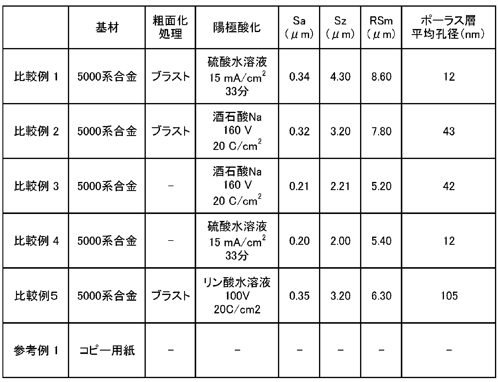
- the cross section of the aluminum member was observed with a transmission electron microscope, and the average pore size of the porous layer was measured.
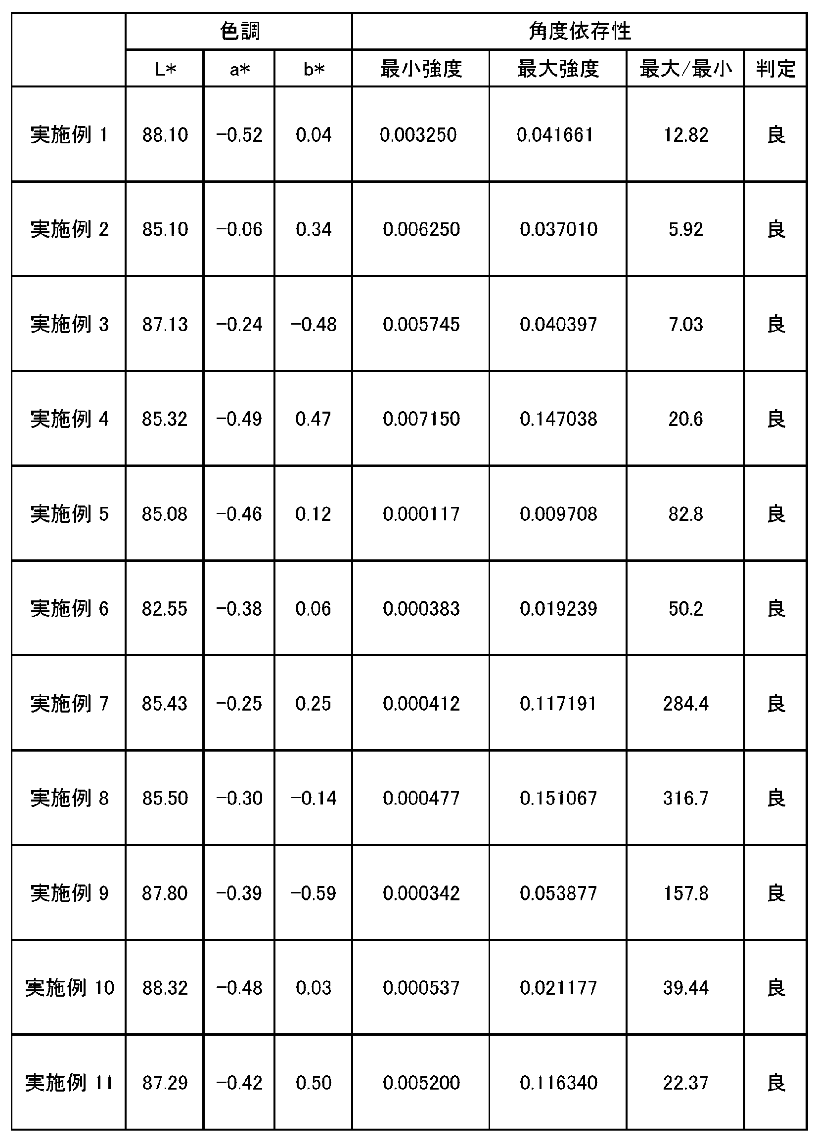
- the color tone of the aluminum member was measured from the surface of the anodized film using a color difference meter CR400 manufactured by Konica Minolta Japan Co., Ltd., and the L * value, a * value and b * value were obtained.
- the illumination / light receiving optical system is a diffuse illumination vertical light receiving method (D / 0)
- the observation condition is a CIE2 ° field color equalization function approximation
- the light source is a C light source
- the color system is a condition of L * a * b * . Measured at.
- the angle dependence of the whiteness of the aluminum member was evaluated using a goniometer (GP-2 type) manufactured by Nikka Densoku Co., Ltd. Specifically, as shown in FIG. 3, the aluminum member 101 was irradiated with light, and the intensity of the light received by the detector 102 was measured.
- the detector 102 is rotatably provided at a predetermined distance around the aluminum member 101. The case where the detector 102 is arranged at a position where the incident angle of the incident light 103 is 45 degrees and the reflected angle of the reflected light 104 is 45 degrees is defined as a detector angle of 0 degrees.
- the reflection intensity on the anodic oxide film side of the reflected light 104 reflected by the aluminum member 101 was measured at intervals of 0.5 degrees in the range of the detector angle of ⁇ 80 degrees to +30 degrees. Then, the ratio of the maximum reflection intensity (maximum reflection intensity / minimum reflection intensity) to the minimum reflection intensity in the range of the detector angle of ⁇ 80 degrees to +10 degrees was calculated. When the ratio is 400 or less, the angle dependence is determined to be "good", and when the ratio is larger than 400, the angle dependence is determined to be "no".
- the L * value is 85 to 100
- the a * value is -1 to +1
- the b * value is -1.5 to +1. It was .5.
- the aluminum member of Example 1 has a higher reflection intensity at a detector angle of -80 degrees to -40 degrees as compared with the aluminum member of Comparative Example 1, and is similar to the copy paper of the reference example.
- the angle dependence of the light reflection intensity was low.
- the maximum reflection intensity with respect to the minimum reflection intensity is obtained when the reflection intensity on the anodic oxide film side is measured at a detector angle of -80 degrees to +10 degrees using a goniometer.
- the ratio of reflection intensity was 400 or less.
- an aluminum member was prepared as follows in order to observe the cross section with a transmission electron microscope.
- Example 12 An aluminum member was produced in the same manner as in Example 2 except that the electrolysis time of the first anodization was 11 minutes, the electrolysis time of the second anodization was 80 seconds, and the pore sealing treatment was not performed.
- the cross section of the aluminum member of Example 12 is processed by FIB (focused ion beam) and magnified by a transmission electron microscope at 2,550 times, 19,500 times and 43,000 times, respectively. It is an image that was made.
- the cross section of the aluminum member of Comparative Example 6 is processed by FIB (focused ion beam) and magnified by a transmission electron microscope at 2,550 times, 19,500 times and 43,000 times, respectively. It is an image that was made.
- FIGS. 11, 12, and 13 the cross section of the aluminum member of Comparative Example 7 is processed by FIB (focused ion beam) and magnified by a transmission electron microscope at 2,550 times, 19,500 times, and 43,000 times, respectively.
- the first porous layer has a plurality of branched holes and the second porous layer has a plurality of linearly extending holes.
- EDS energy dispersive X-ray spectroscopy
- the first porous layer had a plurality of branched holes
- the second porous layer had a plurality of linearly extending holes
- the first porous layer did not have a plurality of branching holes.
- the first porous layer had a plurality of pores having an average pore diameter larger than that of the second porous layer.
Landscapes
- Chemical & Material Sciences (AREA)
- Engineering & Computer Science (AREA)
- Organic Chemistry (AREA)
- Materials Engineering (AREA)
- Metallurgy (AREA)
- Chemical Kinetics & Catalysis (AREA)
- Electrochemistry (AREA)
- Mechanical Engineering (AREA)
- Inorganic Chemistry (AREA)
- Physics & Mathematics (AREA)
- Thermal Sciences (AREA)
- Crystallography & Structural Chemistry (AREA)
- General Chemical & Material Sciences (AREA)
- Laminated Bodies (AREA)
- Other Surface Treatments For Metallic Materials (AREA)
- ing And Chemical Polishing (AREA)
Abstract
Description
図1に示すように、本実施形態のアルミニウム部材1は、基材10と、陽極酸化皮膜20とを備える。以下において、これらの構成要素を説明する。
基材10は、アルミニウム又はアルミニウム合金により形成される。基材10は、例えば、1000系合金、3000系合金、5000系合金、6000系合金又は7000系合金で形成されていてもよい。基材10は、0質量%~10質量%のマグネシウムと、0.1質量%以下の鉄と、0.1質量%以下のケイ素とを含有し、残部がアルミニウム及び不可避不純物であるアルミニウム又はアルミニウム合金により形成されてもよい。基材10は、0質量%~10質量%のマグネシウムと、0.1質量%以下の鉄と、0.1質量%以下のケイ素と、10質量%以下の亜鉛とを含有し、残部がアルミニウム及び不可避不純物であるアルミニウム又はアルミニウム合金により形成されてもよい。
陽極酸化皮膜20は、基材10の表面11に設けられる。このような陽極酸化皮膜20により、耐食性や耐摩耗性などを向上させることができる。陽極酸化皮膜20は、バリア層21と、第1ポーラス層22と、第2ポーラス層23とを含む。
アルミニウム部材1の製造方法は、図2に示すように、粗面化処理工程S1と、エッチング工程S2と、第1陽極酸化工程S3と、第2陽極酸化工程S4と、封孔処理工程S5とを含んでいる。以下、各工程について詳細に説明する。
粗面化処理工程S1では、アルミニウム又はアルミニウム合金により形成される基材10の表面11に凹凸を形成する。粗面化処理工程S1は必須の工程ではないが、アルミニウム部材1の外観をより白色にすることができる。凹凸を形成する基材10は、例えば、所定の元素を有する溶湯の調製、鋳造、圧延、熱処理などにより作製してもよい。また、凹凸を形成する基材10は、鋳造後、圧延後又は熱処理後、特段の表面処理をせずに、そのまま用いてもよい。また、凹凸を形成する基材10は、フライス盤による研削、並びに、エメリー紙、バフ研磨、化学研磨及び電解研磨等により表面11を研磨して用いてもよい。凹凸を形成する基材10の表面11は、算術平均高さSaを100nm未満程度に研磨してもよい。基材10の表面11の算術平均高さSaを100nm未満とすることにより基材10の明度が高くなる。そのため、表面11の凹凸形成、エッチング工程S2、第1陽極酸化工程S3及び第2陽極酸化工程S4を経ても、より紙に近い白色外観を有するアルミニウム部材1を得ることができる。
エッチング工程S2は、必須の工程ではないが、粗面化処理工程S1で形成された基材10の表面11の凹凸の角を取り除き、凹凸を滑らかにすることができる。エッチングの条件は特に限定されず、白色度の高いアルミニウム部材1が得られればよい。
第1陽極酸化工程S3では、凹凸が形成された基材10を、整列して直線状に延びる複数の孔を形成可能な電解液で第1陽極酸化する。第1陽極酸化で用いられる電解液は、第2ポーラス層23中にストレート状の複数の孔を形成可能であれば特に限定されない。電解液は、例えば、硫酸、アミド硫酸、カルボキシル基を含む酸並びにこれらの塩からなる群より選択される少なくとも1種の電解質を含む水溶液であってもよい。カルボキシル基を含む酸としては、蓚酸、サリチル酸、クエン酸、マレイン酸及び酒石酸からなる群より選択される少なくとも1種の酸が挙げられる。これらの中でも、第1陽極酸化の電解液は硫酸、アミド硫酸及びカルボキシル基を有する化合物からなる群より選択される少なくとも一種を含むことが好ましい。第1陽極酸化の電解液は酸性電解液であることが好ましく、電解液のpHは例えば0~2である。電解液における上記電解質の濃度は、例えば10g/L~600g/Lである。
第2陽極酸化工程S4では、第1陽極酸化された基材10を電解液で第2陽極酸化する。第2陽極酸化の電解液は、複数の分岐する孔及び上記直線状に延びる複数の孔よりも大きい平均孔径を有する複数の孔の少なくともいずれか一方を形成可能な電解液である。第2陽極酸化工程S4で用いられる電解液は、第1ポーラス層22中に複数の分岐する孔及び上記直線状に延びる複数の孔よりも大きい平均孔径を有する複数の孔の少なくともいずれか一方を形成可能であれば特に限定されない。電解液は、例えば酒石酸などのようなカルボキシル基を有する化合物、リン酸、クロム酸、ホウ酸及びこれらの塩からなる群より選択される少なくとも一種の電解質を含む水溶液であってもよい。これらの中でも、第2陽極酸化の電解液は、カルボキシル基を有する化合物及びリン酸並びにこれらの塩からなる群より選択される少なくとも一種を含むことが好ましい。具体的には、第2陽極酸化の電解液は酒石酸塩水溶液であることが好ましい。酒石酸塩水溶液は、少なくとも複数の分岐する孔を形成することができる。また、第2陽極酸化の電解液はリン酸水溶液であることも好ましい。リン酸水溶液は上記直線状に延びる複数の孔よりも大きい平均孔径を有する複数の孔を形成することができる。第2陽極酸化の電解液はナトリウム、カリウム及びアンモニアからなる群より選択される少なくとも一種を含有していてもよい。第2陽極酸化の電解液は酸性又はアルカリ性電解液であってもよい。第2陽極酸化の電解液がアルカリ性電解液である場合、電解液のpHは例えば9~14である。電解液をアルカリ性にするため、電解液に水酸化ナトリウムなどを混合してもよい。電解液における上記電解質の濃度は、例えば0.5g/L~200g/Lである。
封孔処理工程S5は必須の工程ではないが、第1ポーラス層22の孔及び第2ポーラス層23の孔の酸化アルミニウムの水和物を封孔することにより、アルミニウム部材1の耐食性を向上させることができる。封孔処理は公知の方法で実施することができ、例えば、高温の水蒸気、酢酸ニッケル水溶液又はフッ化ニッケル等などを用いて実施することができる。
(粗面化処理)
圧延及び焼鈍した厚さ3mmの5000系アルミニウム合金板を、長さ50mm及び幅50mmに切り出したものを基材とした。5000系アルミニウム合金は、マグネシウム4.31質量%、鉄0.02質量%及びケイ素0.02質量%を含有し、残部がアルミニウム(Al)及び不可避不純物である。
凹凸が形成された基材を、温度50℃で濃度50g/Lの水酸化ナトリウム水溶液に60秒間浸漬してエッチングした後、濃度200g/Lの硝酸水溶液に室温(約20℃)で2分間浸漬してスマットを除去した。
エッチングされた基材を、濃度180g/Lの硫酸を含むpH0の酸性水溶液に浸漬し、温度18℃、電流密度15mA/cm2及び電解時間33分の電解条件で第1陽極酸化した。
第1陽極酸化された部材を、濃度106g/Lの酒石酸二ナトリウム・2水和物と濃度3g/Lの水酸化ナトリウムとを含有するpH13のアルカリ性水溶液に浸漬させた。そして、上記部材を、温度5℃、電圧100V、電気量1C/cm2、昇圧速度1V/秒及び電解時間約4分の電解条件で第2陽極酸化した。
第2陽極酸化された部材を、酢酸ニッケル系封孔材によって90℃で30分間封孔処理した。このようにして、本例のアルミニウム部材を作製した。
第2陽極酸化の電圧を160Vとした以外は実施例1と同様にして本例のアルミニウム部材を作製した。
基材として圧延及びT6処理した7000系アルミニウム合金板を用いた以外は実施例2と同様にアルミニウム部材を作製した。上記7000系アルミニウム合金板は、0質量%~10質量%のマグネシウムと、0.1質量%以下の鉄と、0.1質量%以下のケイ素と、10質量%以下の亜鉛とを含有し、残部がアルミニウム及び不可避不純物である。
基材をブラスト処理せず、第2陽極酸化の電圧を20Vとした以外は、実施例1と同様にしてアルミニウム部材を作製した。
基材をブラスト処理せず、第2陽極酸化の電圧を40Vとした以外は、実施例1と同様にしてアルミニウム部材を作製した。
基材をブラスト処理せず、第2陽極酸化の電圧を80Vとした以外は、実施例1と同様にしてアルミニウム部材を作製した。
基材をブラスト処理せず、第2陽極酸化の電圧を120Vとした以外は、実施例1と同様にしてアルミニウム部材を作製した。
基材をブラスト処理せず、第2陽極酸化の電圧を160Vとした以外は、実施例1と同様にしてアルミニウム部材を作製した。
基材をブラスト処理せず、第2陽極酸化の電圧を200Vとした以外は、実施例1と同様にしてアルミニウム部材を作製した。
基材をブラスト処理せず、第2陽極酸化の電圧を240Vとした以外は、実施例1と同様にしてアルミニウム部材を作製した。
第1陽極酸化された部材を、濃度98g/Lのリン酸水溶液(pH1)に浸漬させた。そして、上記部材を、温度5℃、電圧100V、電気量1C/cm2、昇圧速度1V/秒及び電解時間約4分の電解条件で第2陽極酸化した。上記以外は実施例1と同様にしてアルミニウム部材を作製した。
第2陽極酸化をせず、第1陽極酸化された部材を封孔処理した以外は実施例1と同様にして本例のアルミニウム部材を作製した。
エッチングされた基材を、濃度106g/Lの酒石酸二ナトリウム・2水和物と濃度4g/Lの水酸化ナトリウムとを含有するpH13の水溶液に浸漬させた。そして、上記部材を、温度5℃、電圧160V、電気量20C/cm2、昇圧速度1V/秒及び電解時間約4分の条件で陽極酸化した後、封孔処理した。上記以外は、実施例1と同様にしてアルミニウム部材を作製した。
基材をブラスト処理しなかった以外は、比較例2と同様にしてアルミニウム部材を作製した。
基材をブラスト処理しなかった以外は、比較例1と同様にしてアルミニウム部材を作製した。
エッチングされた基材を、濃度98g/Lのリン酸水溶液(pH1)に浸漬させた。そして、上記部材を、温度5℃、電圧100V、電気量20C/cm2、昇圧速度1V/秒及び電解時間約4分の電解条件で陽極酸化した。上記以外は実施例1と同様にしてアルミニウム部材を作製した。
各例で得られたアルミニウム部材の基材表面の凹凸、第1ポーラス層及び第2ポーラス層の平均孔径、アルミニウム部材の色調並びに白色度の角度依存性を以下の通り評価した。
まず、JIS H8688:2013に準じ、上記のようにして得られたアルミニウム部材をリン酸クロム酸(VI)溶液に浸し、陽極酸化皮膜を溶解させて除去した。次に、基材の陽極酸化皮膜側の表面の算術平均高さSa及び最大高さSzを、ブルカー・エイエックスエス株式会社の3次元白色干渉型顕微鏡ContourGT-Iを用いて、ISO25178に準じて測定した。算術平均高さSa及び最大高さSzは、測定範囲を60μm×79μm、対物レンズを115倍、内部レンズを1倍の条件で測定した。
まず、JIS H8688:2013に準じ、上記のようにして得られたアルミニウム部材の陽極酸化皮膜をリン酸クロム酸(VI)溶液に溶解させて除去した。次に、基材の陽極酸化皮膜側の表面における粗さ曲線要素の平均長さRSmを、ブルカー・エイエックスエス株式会社の3次元白色干渉型顕微鏡ContourGT-Iを用いて、JIS B0601:2013に準じて測定した。粗さ曲線要素の平均長さRSmは、カットオフλcを80μm、対物レンズを115倍、内部レンズを1倍、測定距離を79μmの条件で測定した。
アルミニウム部材の断面を透過型電子顕微鏡で観察し、ポーラス層の平均孔径を測定した。
JIS Z8722に準拠し、コニカミノルタジャパン株式会社製の色彩色差計CR400を用い、陽極酸化皮膜の表面からアルミニウム部材の色調を測色し、L*値、a*値及びb*値を求めた。色調は、照明・受光光学系を拡散照明垂直受光方式(D/0)、観察条件をCIE2°視野等色関数近似、光源をC光源、及び、表色系をL*a*b*の条件で測定した。
アルミニウム部材の白色度の角度依存性を、ニッカ電測株式会社製のゴニオフォトメーター(GP-2型)を用いて評価した。具体的には、図3に示すように、アルミニウム部材101に対して光を照射し、検出器102が受光する光の強度を測定した。検出器102は、アルミニウム部材101を中心として所定の距離をおいて回転可能に設けられている。入射光103の入射角が45度及び反射光104の反射角が45度の位置に検出器102が配置される場合を検出器角度0度とした。検出器角度が-80度~+30度の範囲において0.5度間隔でアルミニウム部材101が反射する反射光104の陽極酸化皮膜側の反射強度を測定した。そして、検出器角度が-80度~+10度の範囲における最小反射強度に対する最大反射強度(最大反射強度/最小反射強度)の比を算出した。上記比が400以下である場合には角度依存性が「良」と判定し、上記比が400より大きい場合には角度依存性が「否」と判定した。


第1陽極酸化の電解時間を11分とし、第2陽極酸化の電解時間を80秒とし、封孔処理を実施しなかった以外は実施例2と同様にしてアルミニウム部材を作製した。
第2陽極酸化を実施しなかった以外は実施例12と同様にして本例のアルミニウム部材を作製した。
第1陽極酸化を実施せず、第2陽極酸化の電圧を110V、電解時間を11分とした以外は実施例12と同様にしてアルミニウム部材を作製した。
10 基材
11 表面
20 陽極酸化皮膜
21 バリア層
22 第1ポーラス層
23 第2ポーラス層
24 表面
Claims (11)
- アルミニウム又はアルミニウム合金により形成される基材と、
前記基材の表面と接するバリア層と、前記バリア層の前記基材とは反対側の面に接する第1ポーラス層と、前記第1ポーラス層の前記バリア層とは反対の面に接し、前記第1ポーラス層と接する面から露出する表面に向かって整列して直線状に延びる複数の孔を有する第2ポーラス層とを含む陽極酸化皮膜と、
を備え、
前記第1ポーラス層は複数の分岐する孔及び前記第2ポーラス層よりも大きい平均孔径の複数の孔の少なくともいずれか一方を有する、アルミニウム部材。 - 前記陽極酸化皮膜側から測定した前記アルミニウム部材のL*a*b*表色系におけるL*値は82.5~100であり、a*値は-1~+1であり、b*値は-1.5~+1.5である、請求項1に記載のアルミニウム部材。
- ゴニオフォトメーターを用いて前記陽極酸化皮膜側の反射強度を-80度~+10度の検出器角度で測定した場合において、最小反射強度に対する最大反射強度の比が400以下である、請求項1又は2に記載のアルミニウム部材。
- 前記基材の表面の算術平均高さSaは0.1μm~0.5μmであり、最大高さSzは0.2μm~5μmであり、粗さ曲線要素の平均長さRSmは0.5μm~10μmである、請求項1~3のいずれか一項に記載のアルミニウム部材。
- アルミニウム又はアルミニウム合金により形成される基材を、整列して直線状に延びる複数の孔を形成可能な電解液で第1陽極酸化する第1陽極酸化工程と、
前記第1陽極酸化された基材を電解液で第2陽極酸化する第2陽極酸化工程と、
を含み、
前記第2陽極酸化の電解液は、複数の分岐する孔及び前記直線状に延びる複数の孔よりも大きい平均孔径を有する複数の孔の少なくともいずれか一方を形成可能な電解液である、アルミニウム部材の製造方法。 - 前記第1陽極酸化の電解液は酸性電解液であり、前記第2陽極酸化の電解液は酸性又はアルカリ性電解液である、請求項5に記載のアルミニウム部材の製造方法。
- 前記基材の表面に凹凸を形成する粗面化処理工程をさらに備え、
前記第1陽極酸化工程では前記凹凸が形成された基材を第1陽極酸化する、請求項5又は6に記載のアルミニウム部材の製造方法。 - 前記粗面化処理工程では20μm以下の平均粒子径を有する粒子を前記基材の表面に衝突させて前記凹凸を形成する、請求項7に記載のアルミニウム部材の製造方法。
- 前記第1陽極酸化の電解液は硫酸、アミド硫酸及びカルボキシル基を有する化合物からなる群より選択される少なくとも一種を含む、請求項5~8のいずれか一項に記載のアルミニウム部材の製造方法。
- 前記第2陽極酸化の電解液はカルボキシル基を有する化合物及びリン酸並びにこれらの塩からなる群より選択される少なくとも一種を含む、請求項5~9のいずれか一項に記載のアルミニウム部材の製造方法。
- 前記第2陽極酸化の電解液はナトリウム、カリウム及びアンモニアからなる群より選択される少なくとも一種を含有する、請求項5~9のいずれか一項に記載のアルミニウム部材の製造方法。
Priority Applications (3)
| Application Number | Priority Date | Filing Date | Title |
|---|---|---|---|
| CN202180071625.5A CN116457506A (zh) | 2020-10-23 | 2021-10-14 | 铝构件及其制造方法 |
| KR1020237011000A KR20230092884A (ko) | 2020-10-23 | 2021-10-14 | 알루미늄 부재 및 그 제조 방법 |
| US18/032,802 US12546023B2 (en) | 2020-10-23 | 2021-10-14 | Aluminum member and method for producing same |
Applications Claiming Priority (2)
| Application Number | Priority Date | Filing Date | Title |
|---|---|---|---|
| JP2020178051A JP7435405B2 (ja) | 2020-10-23 | 2020-10-23 | アルミニウム部材及びその製造方法 |
| JP2020-178051 | 2020-10-23 |
Publications (1)
| Publication Number | Publication Date |
|---|---|
| WO2022085548A1 true WO2022085548A1 (ja) | 2022-04-28 |
Family
ID=81290830
Family Applications (1)
| Application Number | Title | Priority Date | Filing Date |
|---|---|---|---|
| PCT/JP2021/037995 Ceased WO2022085548A1 (ja) | 2020-10-23 | 2021-10-14 | アルミニウム部材及びその製造方法 |
Country Status (6)
| Country | Link |
|---|---|
| US (1) | US12546023B2 (ja) |
| JP (1) | JP7435405B2 (ja) |
| KR (1) | KR20230092884A (ja) |
| CN (1) | CN116457506A (ja) |
| TW (1) | TWI893230B (ja) |
| WO (1) | WO2022085548A1 (ja) |
Cited By (1)
| Publication number | Priority date | Publication date | Assignee | Title |
|---|---|---|---|---|
| WO2023203910A1 (ja) * | 2022-04-18 | 2023-10-26 | 日本軽金属株式会社 | アルミニウム部材及びその製造方法 |
Families Citing this family (1)
| Publication number | Priority date | Publication date | Assignee | Title |
|---|---|---|---|---|
| WO2025182328A1 (ja) * | 2024-02-27 | 2025-09-04 | 株式会社豊田中央研究所 | 電気配線部材およびその製造方法 |
Citations (5)
| Publication number | Priority date | Publication date | Assignee | Title |
|---|---|---|---|---|
| JP2013076118A (ja) * | 2011-09-29 | 2013-04-25 | Toshiba Corp | 電気絶縁用注型品およびその製造方法 |
| JP2017025384A (ja) * | 2015-07-23 | 2017-02-02 | 株式会社サクラクレパス | 着色アルミニウム成形体及びその製造方法 |
| JP2017075383A (ja) * | 2015-10-16 | 2017-04-20 | 株式会社Uacj | アルミニウム部材及びその製造方法 |
| JP2018090897A (ja) * | 2016-12-02 | 2018-06-14 | アイシン精機株式会社 | 陽極酸化皮膜の製造方法及び陽極酸化皮膜 |
| JP2019039060A (ja) * | 2017-08-29 | 2019-03-14 | 日本軽金属株式会社 | アルミニウム部材及びその製造方法 |
Family Cites Families (7)
| Publication number | Priority date | Publication date | Assignee | Title |
|---|---|---|---|---|
| JP4048462B2 (ja) * | 1999-08-20 | 2008-02-20 | 日本軽金属株式会社 | アルミニウム材料の表面処理方法 |
| JP3930709B2 (ja) * | 2001-07-09 | 2007-06-13 | 日本軽金属株式会社 | アルミニウム材の表面処理方法及び表面処理アルミニウム材 |
| US9403293B2 (en) * | 2009-09-04 | 2016-08-02 | Sharp Kabushiki Kaisha | Method for forming anodized layer, method for producing mold, method for producing antireflective film, and mold and antireflective film |
| KR101697468B1 (ko) * | 2013-08-29 | 2017-01-17 | 니폰게이긴조쿠가부시키가이샤 | 알루미늄재의 양극 산화 처리 방법 |
| JP2017122267A (ja) * | 2016-01-07 | 2017-07-13 | 株式会社Uacj | 白色アルミニウム材及びその製造方法 |
| JP6474878B1 (ja) * | 2017-11-28 | 2019-02-27 | 株式会社Uacj | アルミニウム部材及びその製造方法 |
| JP6584626B1 (ja) * | 2018-11-30 | 2019-10-02 | 株式会社Uacj | アルミニウム部材及びその製造方法 |
-
2020
- 2020-10-23 JP JP2020178051A patent/JP7435405B2/ja active Active
-
2021
- 2021-10-14 WO PCT/JP2021/037995 patent/WO2022085548A1/ja not_active Ceased
- 2021-10-14 KR KR1020237011000A patent/KR20230092884A/ko active Pending
- 2021-10-14 US US18/032,802 patent/US12546023B2/en active Active
- 2021-10-14 CN CN202180071625.5A patent/CN116457506A/zh active Pending
- 2021-10-18 TW TW110138473A patent/TWI893230B/zh active
Patent Citations (5)
| Publication number | Priority date | Publication date | Assignee | Title |
|---|---|---|---|---|
| JP2013076118A (ja) * | 2011-09-29 | 2013-04-25 | Toshiba Corp | 電気絶縁用注型品およびその製造方法 |
| JP2017025384A (ja) * | 2015-07-23 | 2017-02-02 | 株式会社サクラクレパス | 着色アルミニウム成形体及びその製造方法 |
| JP2017075383A (ja) * | 2015-10-16 | 2017-04-20 | 株式会社Uacj | アルミニウム部材及びその製造方法 |
| JP2018090897A (ja) * | 2016-12-02 | 2018-06-14 | アイシン精機株式会社 | 陽極酸化皮膜の製造方法及び陽極酸化皮膜 |
| JP2019039060A (ja) * | 2017-08-29 | 2019-03-14 | 日本軽金属株式会社 | アルミニウム部材及びその製造方法 |
Cited By (1)
| Publication number | Priority date | Publication date | Assignee | Title |
|---|---|---|---|---|
| WO2023203910A1 (ja) * | 2022-04-18 | 2023-10-26 | 日本軽金属株式会社 | アルミニウム部材及びその製造方法 |
Also Published As
| Publication number | Publication date |
|---|---|
| US20240035187A1 (en) | 2024-02-01 |
| TW202217081A (zh) | 2022-05-01 |
| US12546023B2 (en) | 2026-02-10 |
| JP2022069083A (ja) | 2022-05-11 |
| JP7435405B2 (ja) | 2024-02-21 |
| TWI893230B (zh) | 2025-08-11 |
| KR20230092884A (ko) | 2023-06-26 |
| CN116457506A (zh) | 2023-07-18 |
Similar Documents
| Publication | Publication Date | Title |
|---|---|---|
| KR102156628B1 (ko) | 알루미늄 부재 및 그 제조 방법 | |
| Fernández-López et al. | High performance tribological coatings on a secondary cast Al–Si alloy generated by Plasma Electrolytic Oxidation | |
| WO2022085548A1 (ja) | アルミニウム部材及びその製造方法 | |
| KR20150016885A (ko) | 구리 스트립, 도금된 구리 스트립 및 리드프레임 | |
| EP3088565B9 (en) | Substrate treated with color development, and substrate color development treatment method for same | |
| CN111670270B (zh) | 铝构件及其制造方法 | |
| JP2023072154A (ja) | アルミニウム部材及びその製造方法 | |
| Moon et al. | Lateral growth of PEO films on Al1050 alloy in an alkaline electrolyte | |
| Liu et al. | Effects of Additives on the Microstructure and Tribology Performance of Ta-12W Alloy Micro-Arc Oxidation Coating | |
| WO2023089824A1 (ja) | アルミニウム部材及びその製造方法 | |
| JP2023118330A (ja) | アルミニウム部材及びその製造方法 | |
| WO2023203910A1 (ja) | アルミニウム部材及びその製造方法 | |
| JP7588369B2 (ja) | アルミニウム部材の製造方法 | |
| WO2020026719A1 (ja) | アルミニウム部材及びその製造方法 | |
| CN116648531A (zh) | 用于通过等离子体电解氧化在铝合金基底的表面上产生陶瓷涂层的方法 | |
| JP2025082927A (ja) | アルミニウム部材及びその製造方法 | |
| JP2023118353A (ja) | 紫外線被照射部材、紫外線照射装置用エンクロージャ及び紫外線照射装置 | |
| KR101615457B1 (ko) | 발색 처리된 기재 및 이를 위한 기재의 발색 처리방법 | |
| JP2025140630A (ja) | アルミニウム部材及びその製造方法 | |
| JP2025140626A (ja) | アルミニウム部材及びその製造方法 | |
| JP2025140629A (ja) | アルミニウム部材及びその製造方法 | |
| JP2025140634A (ja) | アルミニウム部材及びその製造方法 | |
| JP2025140659A (ja) | アルミニウム部材及びその製造方法 |
Legal Events
| Date | Code | Title | Description |
|---|---|---|---|
| 121 | Ep: the epo has been informed by wipo that ep was designated in this application |
Ref document number: 21882689 Country of ref document: EP Kind code of ref document: A1 |
|
| WWE | Wipo information: entry into national phase |
Ref document number: 202180071625.5 Country of ref document: CN Ref document number: 18032802 Country of ref document: US |
|
| NENP | Non-entry into the national phase |
Ref country code: DE |
|
| 122 | Ep: pct application non-entry in european phase |
Ref document number: 21882689 Country of ref document: EP Kind code of ref document: A1 |
|
| WWG | Wipo information: grant in national office |
Ref document number: 18032802 Country of ref document: US |