WO2022085141A1 - 光パス設計装置、光パス設計方法及びプログラム - Google Patents
光パス設計装置、光パス設計方法及びプログラム Download PDFInfo
- Publication number
- WO2022085141A1 WO2022085141A1 PCT/JP2020/039655 JP2020039655W WO2022085141A1 WO 2022085141 A1 WO2022085141 A1 WO 2022085141A1 JP 2020039655 W JP2020039655 W JP 2020039655W WO 2022085141 A1 WO2022085141 A1 WO 2022085141A1
- Authority
- WO
- WIPO (PCT)
- Prior art keywords
- allocation
- optical path
- information
- time
- communication
- Prior art date
- Legal status (The legal status is an assumption and is not a legal conclusion. Google has not performed a legal analysis and makes no representation as to the accuracy of the status listed.)
- Ceased
Links
Images







Classifications
-
- H—ELECTRICITY
- H04—ELECTRIC COMMUNICATION TECHNIQUE
- H04J—MULTIPLEX COMMUNICATION
- H04J14/00—Optical multiplex systems
- H04J14/02—Wavelength-division multiplex systems
- H04J14/0227—Operation, administration, maintenance or provisioning [OAMP] of WDM networks, e.g. media access, routing or wavelength allocation
- H04J14/0254—Optical medium access
- H04J14/0267—Optical signaling or routing
-
- H—ELECTRICITY
- H04—ELECTRIC COMMUNICATION TECHNIQUE
- H04J—MULTIPLEX COMMUNICATION
- H04J14/00—Optical multiplex systems
- H04J14/02—Wavelength-division multiplex systems
- H04J14/0227—Operation, administration, maintenance or provisioning [OAMP] of WDM networks, e.g. media access, routing or wavelength allocation
- H04J14/0254—Optical medium access
- H04J14/0267—Optical signaling or routing
- H04J14/0271—Impairment aware routing
-
- H—ELECTRICITY
- H04—ELECTRIC COMMUNICATION TECHNIQUE
- H04B—TRANSMISSION
- H04B10/00—Transmission systems employing electromagnetic waves other than radio-waves, e.g. infrared, visible or ultraviolet light, or employing corpuscular radiation, e.g. quantum communication
- H04B10/27—Arrangements for networking
Definitions
- the present invention relates to an optical path design device, an optical path design method, and a program.
- the control device allocates a new optical path to the increased demand.
- the optical path assigned in this way is not canceled. For example, when the traffic volume increases in an optical network, the already assigned optical path is maintained without being released, and a new optical path is assigned to the increased traffic volume.
- Non-Patent Document 1 there is an optical network design technology aimed at dynamically allocating optical paths to changing demand (see Non-Patent Document 1).
- the control device cancels the allocation of the optical path when the communication ends.
- FIG. 15 is a diagram showing a conventional configuration example of the control device 100.
- the control device 100 includes a generation unit 101, a storage unit 102, an allocation unit 103, and a control unit 104.
- the generation unit 101 uses demand information (information on the client device of the transmission source, device of the client device of the reception source, and information on the traffic traffic amount of communication) for the signal requesting the allocation of the optical path (hereinafter referred to as “allocation request signal”). ).
- the storage unit 102 stores information on an existing optical path in the optical network.
- the allocation unit 103 generates the allocation contents of the optical path according to the allocation request signal.
- the control unit 104 outputs a control signal for setting the parameters of the allocation contents to the node device of the optical network.
- FIG. 16 is a flowchart showing a conventional operation example of the control device 100.
- the allocation unit 103 searches for one or more routes from the start point to the end point in the optical network (step S1).
- the allocation unit 103 detects the current status of frequency allocation for each searched route (step S2).
- the allocation unit 103 determines whether or not there is a route to which the frequency can be allocated at the present time (when the allocation request signal is received) (step S3).
- step S3: YES the allocation unit 103 allocates the route to which the frequency can be assigned at the present time and the frequency to the demand (step S4).
- the allocation unit 103 rejects the allocation request (step S5).
- an object of the present invention is to provide an optical path design device, an optical path design method, and a program capable of suppressing the rejection of a communication optical path allocation request.
- One aspect of the present invention is information on the frequency bandwidth required for communication between the first node device at the start point of the optical path and the second node device at the end point of the optical path, and the future in which the communication is executed.
- the center frequency of the frequency assigned to the communication corresponding to the information of the route connecting the first node device and the second node device and the demand information according to the demand information including the information of the time zone of.
- the scheduling unit that generates the allocation contents including the information of the above and determines the start time and the end time of the allocation of the allocation contents, and the allocation to the communication corresponding to the demand information with the current time as the start time of the allocation.
- It is an optical path design device including a queue for adjusting the timing of allocation of the allocation contents in the future time zone based on the start time and the end time of the allocation when the contents cannot be assigned.
- One aspect of the present invention is an optical path design method executed by an optical path design device, which is required for communication between a first node device at a start point of an optical path and a second node device at an end point of the optical path.
- Information on the route connecting the first node device and the second node device according to demand information including information on the bandwidth of the frequency and information on the future time zone in which the communication is executed.
- a scheduling step that generates allocation contents including information on the central frequency of the frequency assigned to the communication corresponding to the demand information, determines the start time and end time of the allocation of the allocation contents, and the current time is the allocation.
- the timing of allocation of the allocation content in the future time zone is set based on the start time and end time of the allocation.
- An optical path design method that includes a cue step to adjust.
- One aspect of the present invention is a program for operating a computer as the above-mentioned optical path design device.
- FIG. 1 is a diagram showing a configuration example of the communication system 1.
- the communication system 1 includes a plurality of client devices 2, a plurality of routers 3, a plurality of node devices 4, a control device 5, and an optical path design device 6 (optical path design device).
- the number of each of the client device 2, the router 3, the node device 4, the control device 5, and the optical path design device 6 shown in FIG. 1 is an example.
- Router 3 may be a switch.
- the plurality of node devices 4 constitute an optical network.
- the communication system 1 includes, as an example, a node device 4-A, a node device 4-B, a node device 4-C, and a node device 4-D.
- the client device 2-1 is a communication device that is a source of the main signal (data).
- the client device 2-1 transmits a main signal to the router 3-1.
- the router 3 is a device that aggregates the traffic of the client device 2 (end user). That is, the router 3-1 transmits the optical signal transmitted from the client device 2-1 to the optical network.
- each node device 4 relays an optical signal.
- the starting point of the path of the main signal (optical signal) in the optical network is, for example, the node device 4-A.
- the end point of the main signal path in the optical network is, for example, the node device 4-C.
- the node device 4-C outputs the main signal to the router 3-2.
- the router 3-2 transmits an optical signal to the client device 2-2.
- the client device 2-2 is a communication device for receiving the main signal.
- the control device 5 is an optical network management device. That is, the control device 5 is a device that controls (manages) the communication processing of the plurality of node devices 4.
- the control device 5 generates an allocation request signal according to the demand information of the optical path (path and frequency) in the optical network.
- the control device 5 outputs the allocation request signal to the optical path design device 6.
- Demand information includes information on the start point of the optical network connected to the source client device, information on the end point of the optical network connected to the source client device, and the bandwidth of the frequency required for communication (traffic). Amount) information, communication start time information, and communication end time information are included.
- the allocation request signal is a signal that requests the allocation of the optical path at the present time or in the future in response to the demand for the optical path at the present time (current time) or in the future.
- the allocation request signal includes information on the start point and end point of the optical network, information on the frequency bandwidth (traffic amount) of the main signal, information on the communication start time, and information on the communication end time.
- the control device 5 acquires the current allocation content from the optical path design device 6 as a response to the allocation request signal.
- the control device 5 generates parameters (for example, main signal path information, center frequency information, communication start time information, communication end time information) based on the current allocation contents.
- the control device 5 sets the parameters in each node device 4 of the main signal path by using the control signal for setting the parameters.
- the control device 5 sets parameters in each node device 4 of the main signal path using the same control signal as the control signal used when setting the optical path allocation. You may.
- the control protocol is defined as a unique specification by each vendor, for example.
- the control protocol may be NETCONF (RFC6241) / RESTCONF (RFC8040) based on the data model defined by YANG (IETF RFC7950).
- the optical path design device 6 is a device that schedules (determines and manages) the allocation of optical paths (route, frequency, communication start time, communication end time).
- the optical path design device 6 communicates with the control device 5, for example, when it becomes necessary to exchange information regarding the design of the optical path.
- the optical path design device 6 acquires the allocation request signal from the control device 5.
- the optical path design device 6 generates the current allocation contents based on the allocation request signal.
- the optical path design device 6 outputs the current allocation contents to the control device 5 without waiting time.
- the optical path design device 6 sets the optical path in the future communication time zone. Future allocations may be generated based on the allocation request signal so that the path can be assigned.
- the optical path design device 6 adjusts the timing of allocation of route and frequency allocation contents in a future time zone. That is, the optical path design device 6 adjusts the timing (output timing) of the allocation of the future allocation contents until the future allocation contents can be allocated at the present time.
- the optical path design device 6 waits for the generated future allocation content at the present time (waiting). It is output to the control device 5 as the allocation content (when the time has elapsed).
- FIG. 2 is a diagram showing each configuration example of the control device 5 and the optical path design device 6.
- the control device 5 includes a generation unit 50, a storage unit 51, and a control unit 52.
- the optical path design device 6 includes a scheduling unit 60 and a queue 61.
- the optical path design device 6 may include at least one of a generation unit 50, a storage unit 51, and a control unit 52.
- the generation unit 50 acquires or generates demand information.
- the generation unit 50 generates an allocation request signal based on the demand information.
- the generation unit 50 outputs the generated allocation request signal to the scheduling unit 60.
- the source of demand information is determined according to the operation mode of the optical network. For example, the network operator manually inputs the demand information into the generation unit 50. That is, the generation unit 50 acquires the demand information from the network operator.
- the generation unit 50 when the frequency band is temporarily changed according to the result of monitoring the traffic volume status by the generation unit 50, the generation unit 50 generates demand information according to the traffic volume status in the optical network. May be good.
- the generation unit 50 may acquire demand information from each node device 4 of the optical network.
- the generation unit 50 acquires demand information from each node device 4 by using, for example, a route (communication line) different from the route of the main signal.
- the path different from the path of the main signal is, for example, DCN (Data Communication Network).
- the generation unit 50 may acquire demand information from a device other than the optical network. For example, when a service that allows an end user to temporarily occupy a large-capacity optical path is provided to the end user using an optical network, the generation unit 50 uses, for example, a path different from the path of the main signal. , Demand information is acquired from the client device 2.
- the router 3 may generate demand information according to the traffic volume status in the optical network. ..
- the generation unit 50 acquires demand information from each router 3 by using, for example, a route (communication line) different from the route of the main signal.
- the storage unit 51 stores optical network topology information, allocation request information, allocation status information, allocation reservation status, and node device 4 information (for example, address information).
- the allocation reservation information may be stored in the queue 61.
- the allocation request information includes each allocation request signal generated according to each demand information of the optical path.
- the allocation status information is the information of the existing optical path. That is, the allocation status information is the allocation information actually allocated at the present time.
- the allocation reservation status is the information of the optical path for which the allocation is reserved. That is, the allocation reservation information is allocation information that is not actually allocated at the present time.
- FIG. 3 is a diagram showing an example of allocation request information.
- the allocation request signals are registered in the allocation request information in the order acquired by the scheduling unit 60.
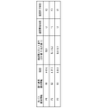
- the allocation request identification information, the start point, the end point, the number of frequency slots, the communication start time, the communication end time, and the communication duration are associated with each other.
- the starting point is the starting point of the path in the optical network, which is the node device 4-A in FIG.
- the end point is the end point of the path in the optical network, which is node device 4-C in FIG.
- the number of frequency slots is determined according to the frequency bandwidth (traffic amount) required for communication.
- the communication duration is the time length of the communication time zone (the time zone from the start time to the end time of the optical path allocation).
- FIG. 4 is a diagram showing the allocation status information.
- the optical path identification information, the allocation request identification information, the route, the frequency slot number, the communication start time, and the communication end time are associated with each other.
- the optical path identification information is the identification information of the optical path in the optical network.
- the allocation request identification information is the identification information of the allocation request signal generated according to the demand information.
- the route represents a route connecting the node devices 4 that relay the main signal.
- the route "ABC" represents a route connecting the node device 4-A, the node device 4-B, and the node device 4-C in the optical network.
- the frequency slot number is the number of the slot in the frequency band.
- the communication start time is the start time of the communication time zone (the time zone from the start time to the end time of the allocation of the optical path).
- the communication end time is the end time of the communication time zone.
- FIG. 5 is a diagram showing an example of allocation reservation information.
- the optical path identification information, the allocation request identification information, the route, the frequency slot number, the communication start time, and the communication end time are associated with each other. In this way, the items of the allocation status information and the items of the allocation reservation information are common to each other.
- the scheduling unit 60 acquires the topology information of the optical network from the storage unit 51.
- the scheduling unit 60 may acquire the allocation status information and the allocation reservation information from the storage unit 51.
- the scheduling unit 60 acquires the allocation request signal from the generation unit 50.
- the scheduling unit 60 executes the communication accommodation design. That is, the scheduling unit 60 schedules the allocation of the allocation contents between the main signal path, the frequency band of the main signal, and the communication time zone (allocation time zone) according to the allocation request signal. The scheduling unit 60 allocates optical path identification information to the demand information corresponding to the allocation request signal acquired from the generation unit 50.
- the scheduling unit 60 If the scheduling unit 60 can be allocated at the present time, the scheduling unit 60 outputs the current allocation contents determined by the scheduling to the control device 5 without waiting time. As a result, the current allocation contents are set in the node device 4 by the control device 5 without waiting time.
- the scheduling unit 60 registers the allocation request signal in the allocation status information stored in the storage unit 51.
- the scheduling unit 60 If the scheduling unit 60 can allocate at a future time within the range that satisfies the demand demand, the scheduling unit 60 adds the future allocation contents determined by scheduling to the queue 61.
- the parameters of the allocation contents added to the queue 61 are set in the node device 4 by the control device 5 after the waiting time has elapsed.
- the scheduling unit 60 registers the allocation request signal in the allocation reservation information stored in the storage unit 51 or the queue 61.
- the allocation information (route, frequency slot number, communication start time, communication end time) associated with the allocation request identification information "R4" of the optical path identification information "P4" shown in FIG. 5 has a waiting time.
- the information is output from the queue 61 to the control device 5 and set in the node device 4 by the control device 5.
- the scheduling unit 60 or the control unit 52 deletes the allocation information associated with the allocation request identification information "R4" of the optical path identification information "P4" from the allocation reservation information and registers it in the allocation status information. ..
- the scheduling unit 60 When the scheduling unit 60 further acquires the allocation request signal from the generation unit 50, the scheduling unit 60 adds the allocation request signal to the allocation request information.
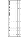
- FIG. 6 is a diagram showing an example of allocation request information to which an allocation request signal is added. Compared with the allocation request information shown in FIG. 3, in FIG. 6, allocation request signals of the allocation request identification information “R6”, “R7”, and “R8” are added, respectively.
- the scheduling unit 60 arranges the communication start time and the communication end time requested by using the allocation request signal in chronological order based on the allocation status information shown in FIG. 4 and the allocation reservation information shown in FIG. ..
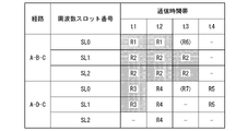
- FIG. 7 is a diagram showing an example of a requested communication time zone (time from the communication start time to the communication end time).
- the requested communication time zone is shown in a time series from the communication start time “t1” to the communication end time “t4”.
- the optical path of the route "ABC" and the frequency slot "SL0" is assigned the allocation request identification information "R1" in the communication time zone from the communication start time "t1" to the communication end time "t2".
- the communication start time and the communication end time newly requested from the generation unit 50 using the allocation request signal of the allocation request identification information “R6” are arbitrary “-” times, respectively. be. Further, the communication duration (length of communication time zone) newly requested from the generation unit 50 using the allocation request signal is "T1", and the number of frequency slots (frequency bandwidth) is "1". be.
- the scheduling unit 60 uses the optical path of the path “ABC” and the frequency slot “SL0” at the time “t3” and the optical path 4 of each node device of the path “ABC” at the time “t3”. Allocate to the demand of.
- the scheduling unit 60 or the control unit 52 registers the allocation request signal of the allocation request identification information "R6" in the allocation status information.
- the communication start time newly requested from the generation unit 50 using the allocation request signal of the allocation request identification information “R7” is an arbitrary “ ⁇ ” time.
- the requested communication end time is the time “t4".
- the communication duration (length of communication time zone) newly requested from the generation unit 50 using the allocation request signal is "T1", and the number of frequency slots (frequency bandwidth) is "2". be.
- the scheduling unit 60 makes the optical path of the path “ADC” and the frequency slot “SL0” at the time “t3” or the time “t4” without waiting time, and the path “ADC”. Allocate to the demand of the optical path using each node device 4 of.
- the scheduling unit 60 or the control unit 52 registers the allocation request signal of the allocation request identification information "R7" in the allocation status information.
- the communication start time newly requested from the generation unit 50 using the allocation request signal of the allocation request identification information “R8” is the time “t3”.
- the requested communication end time is the time “t4".
- the communication duration newly requested from the generation unit 50 using the allocation request signal is "T2", and the number of frequency slots (frequency bandwidth) is "2".
- the scheduling unit 60 rejects the allocation request signal of the allocation request identification information “R8”.
- the queue 61 temporarily holds future allocation contents (allocation reservation information). After the waiting time has elapsed, the queue 61 outputs the held future allocation contents to the control device 5 as the current allocation contents. As a result, the future allocation contents are set in the node device 4 by the control device 5 after the waiting time has elapsed.
- the control unit 52 acquires the current allocation content from the scheduling unit 60.
- the control unit 52 acquires the information of the node device 4 from the storage unit 51.
- the current allocation content acquired from the scheduling unit 60 is the current allocation content transmitted from the scheduling unit 60 without waiting time.
- the control unit 52 acquires the future allocation contents held in the queue 61 from the queue 61 as the current allocation contents when the communication start time becomes the current time.
- the current allocation content acquired from the queue 61 is a future allocation content transmitted from the scheduling unit 60 after the lapse of the waiting time until the future time becomes the current time.
- the control unit 52 generates a control signal for setting the parameter of the allocation content according to the current allocation content.
- the control unit 52 outputs a control signal for setting the allocation of the optical path to each node device 4 of the optical network.
- the control unit 52 outputs a control signal for canceling the allocation of the optical path to each node device 4 of the optical network.
- the parameters of the allocation contents are set in each node device 4.
- control unit 52 Since the waiting time increases as the demand for the optical path increases, the control unit 52 temporarily holds the future allocation contents rather than setting the current allocation contents acquired from the scheduling unit 60 in the node device 4. It may be prioritized to set the current allocation contents acquired from the queue 61 to the node device 4. This makes it possible to reduce the waiting time.
- FIG. 8 is a flowchart showing an operation example (accommodation design algorithm) of the optical path design device 6.
- the scheduling unit 60 records the allocation request signal acquired from the generation unit 50 in the allocation request information stored in the storage unit 51.
- the scheduling unit 60 acquires the allocation status information and the allocation reservation information from the storage unit 51.
- the scheduling unit 60 searches for one or more routes from the start point to the end point in the optical network (step S101).
- the scheduling unit 60 detects the current status of frequency allocation and the reservation status of frequency allocation for each searched route based on the allocation status information and the allocation reservation information (step S102).
- the scheduling unit 60 searches for a route to which a frequency can be assigned at the present time (current time) based on the current state of allocation (step S103).
- the scheduling unit 60 determines whether or not there is a route to which a frequency can be assigned at the present time (step S104). When it is determined that there is a route to which the frequency can be assigned at the present time (step S104: YES), the scheduling unit 60 uses the route to which the frequency can be assigned at the present time and the frequency to meet the demand for using the plurality of node devices 4. Allocate (step S105).
- the scheduling unit 60 searches for a route to which the frequency can be assigned in the future based on the reservation status of the allocation (step S106). ). The scheduling unit 60 determines whether or not there is a route to which a frequency can be assigned in the future (step S107). When it is determined that there is a route to which the frequency can be assigned in the future (step S107: YES), the scheduling unit 60 determines the route to which the frequency can be assigned in the future, the frequency, and the future communication time zone (reserved time). Is assigned to the demand using the plurality of node devices 4 (step S108).
- the scheduling unit 60 reserves the allocation of future allocation contents by adding the future allocation contents to the queue 61 (step S109). When it is determined that there is no route to which the frequency can be assigned in the future (step S107: NO), the scheduling unit 60 rejects the allocation request (step S110).
- the scheduling unit 60 is used for communication corresponding to the route information connecting the node device 4-A (first node device) and the node device 4-C (second node device) and the demand information.
- the allocation contents including the information of the central frequency of the allocated frequency are generated according to the demand information.
- the demand information includes information on the frequency bandwidth required for communication between the node device 4-A at the start point of the optical path and the node device 4-C at the end point of the optical path, and the future time when the communication is executed. Includes band information.
- the scheduling unit 60 determines the start time and end time of the allocation of the allocation contents.
- the queue 61 allocates the allocation contents in the future time zone based on the start time and the end time of the allocation. Adjust the timing of. In this way, in the accommodation design, not only the scheduling considering the current allocation contents (current demand) but also the scheduling considering the allocation contents (future demand) added to the queue 61 (route, frequency and communication start). Allocation of time and communication end time) is executed.
- the future allocation content includes not only the route and frequency information but also the communication start time and communication end time information, there is no route and frequency that can be allocated when the scheduling unit 60 receives the demand information. Also, it is possible to reserve the setting of the parameter of the allocation content in the node device 4 in the future time zone.
- allocation contents reserved for allocation are assigned to the demand of the optical path in preference to the current allocation contents. This makes it possible to operate an optical network that meets the demand for optical paths when the demand arises.
- FIG. 9 is a diagram showing a first modification example of each configuration of the control device 5 and the optical path design device 6.
- the current allocation content passes through the queue 61. That is, the scheduling unit 60 outputs the current allocation contents to the queue 61.
- the queue 61 outputs the current allocation contents to the control unit 52 without waiting time.
- FIG. 10 is a diagram showing a second modification example of each configuration of the control device 5 and the optical path design device 6.
- the optical path design device 6 is independent of the control device 5 as a single device.
- the optical path design device 6 is provided in the control device 5 as one of the functional units of the control device 5.
- FIG. 11 is a flowchart showing an operation example of the optical path design device 6.
- the scheduling unit 60 searches for one or more routes from the start point to the end point in the optical network (step S201).
- the scheduling unit 60 detects the current status of frequency allocation and the reservation status of frequency allocation for each searched route based on the allocation status information and the allocation reservation information (step S202).
- the scheduling unit 60 searches for the time during which frequency allocation is possible for each route based on the current status of frequency allocation and the reservation status of frequency allocation (step S203).
- the scheduling unit 60 determines whether or not there is a time in which the frequency can be allocated within the range that satisfies the allocation request (whether or not there is a free time that satisfies the time requirement of demand) (step S204).
- the scheduling unit 60 selects a route to which the frequency can be assigned and a frequency within a range satisfying the allocation request (step S205).
- the scheduling unit 60 determines whether or not a route to which a frequency can be assigned is selected at the present time (step S206). When it is determined that the route to which the frequency can be assigned at the present time is selected (step S206: YES), the scheduling unit 60 demands that the route to which the frequency can be assigned at the present time and the frequency are used by the plurality of node devices 4. (Step S207). When it is determined that the route to which the frequency can be assigned is not selected at the present time (step S206: NO), the scheduling unit 60 allocates the future allocation contents by adding the future allocation contents to the queue 61. Make a reservation (step S208). When it is determined that there is no time in which the frequency can be allocated (step S204: NO), the scheduling unit 60 rejects the allocation request (step S209).
- the scheduling unit 60 determines whether or not there is a time in which the frequency can be allocated within the range satisfying the allocation request. When it is determined that there is a time in which the frequency can be assigned, the scheduling unit 60 selects a route to which the frequency can be assigned and a frequency within a range satisfying the allocation request.
- the third embodiment differs from the first embodiment and the second embodiment in that the future allocation contents added to the queue are reassigned to the new demand of the optical path.
- the differences between the first embodiment and the second embodiment will be mainly described.
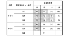
- FIG. 12 is a diagram showing an example of the requested communication time zone.
- the allocation request signal of the allocation request identification information "R8" following the allocation request identification information "R7" added to the queue 61 is rejected.
- the scheduling unit 60 reallocates the allocation content added to the queue 61 to the demand of the optical path. For example, when the allocation request signal of the allocation request identification information "R8" is rejected, the scheduling unit 60 regarding one or more allocation request identification information from the allocation request identification information "R4" to the allocation request identification information "R8". , Reallocate the allocation to the demand of the optical path.
- the scheduling unit 60 preferentially allocates the allocation contents to the communication in which the start time of the future time zone included in the demand information is closer to the start time of the allocation of the allocation contents.
- the time "t3" and “t4" of the frequency slots "SL0" and “SL1" of the route "ADC" are assigned to the demand corresponding to the allocation request signal of the allocation request identification information "R8". In this case, it is necessary to reallocate the allocation request identification information "R5" and "R7" for which allocation has already been reserved.
- the scheduling unit 60 allocates the free time “t4” to the demand corresponding to the allocation request signal of the allocation request identification information “R7”.
- FIG. 13 is a flowchart showing an operation example of the optical path design device 6.
- Each operation from step S301 to step S308 is the same as each operation from step S201 to step S208 shown in FIG.
- the scheduling unit 60 reassigns the route and the frequency to which the frequency can be assigned at present or in the future to the plurality of node devices 4. (Step S309).
- the scheduling unit 60 reassigns the routes and frequencies to which frequencies can be assigned at present or in the future to the plurality of node devices 4. This makes it possible to further suppress the rejection of the communication optical path allocation request. In addition, it is possible to improve the accommodation efficiency of communication. For example, it is possible to meet the demand corresponding to the allocation request signal of the subsequent allocation request identification information.
- FIG. 14 is a diagram showing a hardware configuration example of the optical path design device 6 in each embodiment.
- a part or all of each functional unit of the optical path design device 6 is stored in a memory 602 in which a processor 600 such as a CPU (Central Processing Unit) has a non-volatile recording medium (non-temporary recording medium). It is realized as software by executing the program.
- the program may be recorded on a computer-readable recording medium.
- Computer-readable recording media include, for example, flexible disks, optomagnetic disks, portable media such as ROM (ReadOnlyMemory) and CD-ROM (CompactDiscReadOnlyMemory), and storage of hard disks built into computer systems. It is a non-temporary recording medium such as the device 601.
- each functional part of the optical path design device 6 is, for example, an LSI (Large Scale Integrated circuit), an ASIC (Application Specific Integrated Circuit), a PLD (Programmable Logic Device), or an FPGA (Field Programmable Gate Array). It may be realized by using hardware including an electronic circuit (electronic circuit or circuitry) using the above.
- the present invention is applicable to an optical network communication system.
Landscapes
- Engineering & Computer Science (AREA)
- Computer Networks & Wireless Communication (AREA)
- Signal Processing (AREA)
- Computing Systems (AREA)
- Physics & Mathematics (AREA)
- Electromagnetism (AREA)
- Data Exchanges In Wide-Area Networks (AREA)
Priority Applications (3)
| Application Number | Priority Date | Filing Date | Title |
|---|---|---|---|
| US18/029,726 US12494859B2 (en) | 2020-10-22 | 2020-10-22 | Optical path design apparatus, optical path design method and program |
| PCT/JP2020/039655 WO2022085141A1 (ja) | 2020-10-22 | 2020-10-22 | 光パス設計装置、光パス設計方法及びプログラム |
| JP2022556318A JP7510082B2 (ja) | 2020-10-22 | 2020-10-22 | 光パス設計装置、光パス設計方法及びプログラム |
Applications Claiming Priority (1)
| Application Number | Priority Date | Filing Date | Title |
|---|---|---|---|
| PCT/JP2020/039655 WO2022085141A1 (ja) | 2020-10-22 | 2020-10-22 | 光パス設計装置、光パス設計方法及びプログラム |
Publications (1)
| Publication Number | Publication Date |
|---|---|
| WO2022085141A1 true WO2022085141A1 (ja) | 2022-04-28 |
Family
ID=81289741
Family Applications (1)
| Application Number | Title | Priority Date | Filing Date |
|---|---|---|---|
| PCT/JP2020/039655 Ceased WO2022085141A1 (ja) | 2020-10-22 | 2020-10-22 | 光パス設計装置、光パス設計方法及びプログラム |
Country Status (3)
| Country | Link |
|---|---|
| US (1) | US12494859B2 (https=) |
| JP (1) | JP7510082B2 (https=) |
| WO (1) | WO2022085141A1 (https=) |
Cited By (1)
| Publication number | Priority date | Publication date | Assignee | Title |
|---|---|---|---|---|
| WO2024241399A1 (ja) * | 2023-05-19 | 2024-11-28 | 日本電信電話株式会社 | 光パス設計装置、光パス設計方法、および、光パス設計プログラム |
Citations (2)
| Publication number | Priority date | Publication date | Assignee | Title |
|---|---|---|---|---|
| JP2017147517A (ja) * | 2016-02-15 | 2017-08-24 | 日本電信電話株式会社 | リソース割当計算装置、リソース割当計算方法、及びプログラム |
| CN111010626A (zh) * | 2019-11-11 | 2020-04-14 | 郑州轻工业学院 | 一种弹性光网络中有远见的提前预留业务资源分配方法 |
Family Cites Families (38)
| Publication number | Priority date | Publication date | Assignee | Title |
|---|---|---|---|---|
| JPH10117215A (ja) | 1996-08-22 | 1998-05-06 | Furukawa Electric Co Ltd:The | ネットワーク間接続方法及びその装置 |
| DE19945663A1 (de) | 1999-09-23 | 2001-04-05 | Siemens Ag | Internet-Telefonadapter |
| US6678524B1 (en) | 2000-05-31 | 2004-01-13 | Telefonaktiebolaget Lm Ericsson (Publ) | Bearer selection in a mobile communication system having both circuit-switched and packet-switched bearers |
| JP4095325B2 (ja) | 2002-03-29 | 2008-06-04 | キヤノン株式会社 | 画像配信方法およびその動作処理を実行するプログラムおよびそのプログラムを記憶した記憶媒体、および画像配信装置および画像受信装置 |
| JP4458767B2 (ja) | 2003-04-16 | 2010-04-28 | エボリウム・エス・アー・エス | 携帯電話システム |
| US7246172B2 (en) | 2003-06-06 | 2007-07-17 | Matsushita Electric Industrial Co., Ltd. | Static dense multicast path and bandwidth management |
| JP3937337B2 (ja) | 2003-08-15 | 2007-06-27 | 日本電信電話株式会社 | 配信レート制御方法及びシステム |
| KR20060088939A (ko) * | 2005-02-02 | 2006-08-07 | 삼성전자주식회사 | 광 네트워크에서의 광채널 할당시스템 및 그 방법 |
| US20070079307A1 (en) | 2005-09-30 | 2007-04-05 | Puneet Dhawan | Virtual machine based network carriers |
| US7822065B2 (en) | 2007-01-07 | 2010-10-26 | Wei Lu | Open wireless architecture (OWA) medium access control (MAC) processing architecture for future mobile terminal |
| US20080235361A1 (en) | 2007-03-21 | 2008-09-25 | David Crosbie | Management layer method and apparatus for dynamic assignment of users to computer resources |
| JP5164628B2 (ja) | 2008-03-24 | 2013-03-21 | 株式会社日立製作所 | ネットワークスイッチ装置、サーバシステム及びサーバシステムにおけるサーバ移送方法 |
| TW201007574A (en) | 2008-08-13 | 2010-02-16 | Inventec Corp | Internet server system and method of constructing and starting a virtual machine |
| EP2175607A1 (en) | 2008-10-08 | 2010-04-14 | NEC Corporation | Method for establishing a thin client session |
| US20110126197A1 (en) | 2009-11-25 | 2011-05-26 | Novell, Inc. | System and method for controlling cloud and virtualized data centers in an intelligent workload management system |
| US9141420B2 (en) | 2010-11-04 | 2015-09-22 | Alcatel Lucent | Overload control in a cloud computing environment |
| US9785478B1 (en) | 2010-11-12 | 2017-10-10 | Vmware, Inc. | Mass migration of desktop deployments to virtual desktop infrastructures |
| WO2013003327A1 (en) * | 2011-06-27 | 2013-01-03 | University Of Massachusetts | Dynamic advance reservation with delayed allocation |
| US9461881B2 (en) | 2011-09-30 | 2016-10-04 | Commvault Systems, Inc. | Migration of existing computing systems to cloud computing sites or virtual machines |
| US8719534B1 (en) | 2012-03-21 | 2014-05-06 | Netapp, Inc. | Method and system for generating a migration plan |
| KR101384934B1 (ko) | 2012-06-29 | 2014-04-14 | 인텔렉추얼디스커버리 주식회사 | 모바일 노드의 이동을 처리하기 위한 방법 및 장치 |
| EP2687982A1 (en) | 2012-07-16 | 2014-01-22 | NTT DoCoMo, Inc. | Hierarchical system for managing a plurality of virtual machines, method and computer program |
| US20140181984A1 (en) | 2012-12-21 | 2014-06-26 | International Business Machines Corporation | Method and apparatus for authentication of solution topology |
| US9069608B2 (en) | 2013-03-06 | 2015-06-30 | Vmware, Inc. | Method and system for providing a roaming remote desktop |
| EP3041311B1 (en) | 2013-08-26 | 2023-10-04 | Nec Corporation | Communication apparatus and method in communication system, and communication path control apparatus and method |
| JP6001516B2 (ja) | 2013-09-24 | 2016-10-05 | 株式会社日立製作所 | 通信システム及び通信装置 |
| US20150363219A1 (en) | 2014-03-14 | 2015-12-17 | Avni Networks Inc. | Optimization to create a highly scalable virtual netork service/application using commodity hardware |
| EP3208956B1 (en) * | 2014-11-28 | 2019-08-28 | Nippon Telegraph and Telephone Corporation | Framer and framing method |
| US9146769B1 (en) | 2015-04-02 | 2015-09-29 | Shiva Shankar | Systems and methods for copying a source machine to a target virtual machine |
| US20170235737A1 (en) | 2016-02-12 | 2017-08-17 | Nutanix, Inc. | Entity database ranking |
| US10785144B2 (en) | 2016-12-30 | 2020-09-22 | Equinix, Inc. | Latency equalization |
| US11089105B1 (en) | 2017-12-14 | 2021-08-10 | Pure Storage, Inc. | Synchronously replicating datasets in cloud-based storage systems |
| US10929195B2 (en) | 2017-08-07 | 2021-02-23 | Dynavisor, Inc. | Method and system for cloud virtualization |
| US10855537B2 (en) | 2018-04-24 | 2020-12-01 | Vmware, Inc. | Methods and apparatus for template driven infrastructure in virtualized server systems |
| EP3564687B1 (en) | 2018-05-03 | 2023-02-22 | Siemens Aktiengesellschaft | Determination of power transmission line parameters using asynchronous measurements |
| CN111416794B (zh) | 2019-01-08 | 2022-07-29 | 华为技术有限公司 | 一种数据传输方法及电子设备 |
| US11301407B2 (en) | 2019-01-08 | 2022-04-12 | Intel Corporation | Technologies for accelerator fabric protocol multipathing |
| US11496404B2 (en) | 2019-06-27 | 2022-11-08 | Google Llc | Congestion control for low latency datacenter networks |
-
2020
- 2020-10-22 WO PCT/JP2020/039655 patent/WO2022085141A1/ja not_active Ceased
- 2020-10-22 JP JP2022556318A patent/JP7510082B2/ja active Active
- 2020-10-22 US US18/029,726 patent/US12494859B2/en active Active
Patent Citations (2)
| Publication number | Priority date | Publication date | Assignee | Title |
|---|---|---|---|---|
| JP2017147517A (ja) * | 2016-02-15 | 2017-08-24 | 日本電信電話株式会社 | リソース割当計算装置、リソース割当計算方法、及びプログラム |
| CN111010626A (zh) * | 2019-11-11 | 2020-04-14 | 郑州轻工业学院 | 一种弹性光网络中有远见的提前预留业务资源分配方法 |
Non-Patent Citations (4)
| Title |
|---|
| "Overview of Elastic Optical Networks", PROCEEDINGS OF THE 2013 IEICE COMMUNICATIONS SOCIETY CONFERENCE. ADAPTIVE SPECTRUM ALLOCATION, 3 September 2013 (2013-09-03) * |
| AFSHARLAR PEGAH; DEYLAMSALEHI ARASH; PLANTE JEREMY M.; ZHAO JUZI; VOKKARANE VINOD M.: "Routing and spectrum assignment with delayed allocation in elastic optical networks", JOURNAL OF OPTICAL COMMUNICATIONS AND NETWORKING, IEEE, USA, vol. 9, no. 3, 1 March 2017 (2017-03-01), USA, XP011646024, ISSN: 1943-0620, DOI: 10.1364/JOCN.9.00B101 * |
| LU, WEI ET AL.: "Dynamic Service Provisioning of Advance Reservation Requests in Elastic Optical Networks", JOURNAL OF LIGHTWAVE TECHNOLOGY, vol. 31, no. 10, 26 March 2013 (2013-03-26), pages 1621 - 1627, XP011499993, DOI: 10.1109/JLT.2013.2254468 * |
| SUGIHARA, SEITARO ET AL.: "Routing and Spectrum Assignment for Immediate and Advance Reservation Requests in Elastic Optical Networks", IEICE TECHNICAL REPORT, vol. 115, no. 434, 21 January 2016 (2016-01-21) * |
Cited By (1)
| Publication number | Priority date | Publication date | Assignee | Title |
|---|---|---|---|---|
| WO2024241399A1 (ja) * | 2023-05-19 | 2024-11-28 | 日本電信電話株式会社 | 光パス設計装置、光パス設計方法、および、光パス設計プログラム |
Also Published As
| Publication number | Publication date |
|---|---|
| JP7510082B2 (ja) | 2024-07-03 |
| JPWO2022085141A1 (https=) | 2022-04-28 |
| US20230412299A1 (en) | 2023-12-21 |
| US12494859B2 (en) | 2025-12-09 |
Similar Documents
| Publication | Publication Date | Title |
|---|---|---|
| JP4806466B2 (ja) | パス管理制御方法、パス管理制御プログラム、パス管理制御装置およびパス管理制御システム | |
| JP3797966B2 (ja) | ラベルスイッチネットワークにおけるリソース管理方法 | |
| JP5320512B2 (ja) | 中継器、中継器の制御方法、およびプログラム | |
| JP3816390B2 (ja) | サービス割り当て装置 | |
| JP7513113B2 (ja) | 制御装置、リソース割当方法、及びプログラム | |
| CN108432191A (zh) | 网络控制器间的通信 | |
| CN104348754B (zh) | 一种光突发环网的带宽分配方法和装置 | |
| JP6458560B2 (ja) | 波長割当方法及び波長割当装置 | |
| WO2014169884A2 (zh) | 动态带宽调度方法、装置及计算机存储介质 | |
| CN116348852A (zh) | 管理向计算环境中的租户的互联网协议(ip)地址分配 | |
| US8391178B2 (en) | Route allocation apparatus and method | |
| JP2011101151A (ja) | タイムスロット割り当て方法、プログラム及び装置 | |
| JP7510082B2 (ja) | 光パス設計装置、光パス設計方法及びプログラム | |
| WO2018161795A1 (zh) | 一种路由优先级配置方法、设备以及控制器 | |
| JP6663384B2 (ja) | リソース割当方法及びリソース割当装置 | |
| JP6678833B1 (ja) | ネットワークコントローラ | |
| US20040190490A1 (en) | Device for determining switching paths in a label switched communication network in the presence of selection attributes | |
| JP4589847B2 (ja) | 動的制御用ネットワークリソース制御方法および動的制御用ネットワークリソース制御装置 | |
| JP5807678B2 (ja) | 光ネットワークシステム、通信制御装置、通信制御方法、および通信制御プログラム | |
| JP3783664B2 (ja) | ルータ装置およびプログラム | |
| WO2022085147A1 (ja) | 光パス設計装置、光パス設計方法及びプログラム | |
| WO2012114747A1 (ja) | 通信ネットワークシステム、ノード装置およびパス制御方法 | |
| JP2016134850A (ja) | ネットワーク管理装置及びネットワーク管理方法 | |
| JP3923909B2 (ja) | リソース管理システムおよび方法 | |
| JP6810506B2 (ja) | 光ネットワークのパスに割り当てるリソースを決定する決定装置 |
Legal Events
| Date | Code | Title | Description |
|---|---|---|---|
| ENP | Entry into the national phase |
Ref document number: 2022556318 Country of ref document: JP Kind code of ref document: A |
|
| NENP | Non-entry into the national phase |
Ref country code: DE |
|
| 122 | Ep: pct application non-entry in european phase |
Ref document number: 20958693 Country of ref document: EP Kind code of ref document: A1 |