WO2022080344A1 - 物品収容装置 - Google Patents
物品収容装置 Download PDFInfo
- Publication number
- WO2022080344A1 WO2022080344A1 PCT/JP2021/037660 JP2021037660W WO2022080344A1 WO 2022080344 A1 WO2022080344 A1 WO 2022080344A1 JP 2021037660 W JP2021037660 W JP 2021037660W WO 2022080344 A1 WO2022080344 A1 WO 2022080344A1
- Authority
- WO
- WIPO (PCT)
- Prior art keywords
- article
- accommodating
- advancing
- door
- retreating
- Prior art date
- Legal status (The legal status is an assumption and is not a legal conclusion. Google has not performed a legal analysis and makes no representation as to the accuracy of the status listed.)
- Ceased
Links
Images




Classifications
-
- B—PERFORMING OPERATIONS; TRANSPORTING
- B60—VEHICLES IN GENERAL
- B60K—ARRANGEMENT OR MOUNTING OF PROPULSION UNITS OR OF TRANSMISSIONS IN VEHICLES; ARRANGEMENT OR MOUNTING OF PLURAL DIVERSE PRIME-MOVERS IN VEHICLES; AUXILIARY DRIVES FOR VEHICLES; INSTRUMENTATION OR DASHBOARDS FOR VEHICLES; ARRANGEMENTS IN CONNECTION WITH COOLING, AIR INTAKE, GAS EXHAUST OR FUEL SUPPLY OF PROPULSION UNITS IN VEHICLES
- B60K1/00—Arrangement or mounting of electrical propulsion units
- B60K1/04—Arrangement or mounting of electrical propulsion units of the electric storage means for propulsion
-
- B—PERFORMING OPERATIONS; TRANSPORTING
- B60—VEHICLES IN GENERAL
- B60R—VEHICLES, VEHICLE FITTINGS, OR VEHICLE PARTS, NOT OTHERWISE PROVIDED FOR
- B60R5/00—Compartments within vehicle body primarily intended or sufficiently spacious for trunks, suit-cases, or the like
- B60R5/04—Compartments within vehicle body primarily intended or sufficiently spacious for trunks, suit-cases, or the like arranged at rear of vehicle
-
- B—PERFORMING OPERATIONS; TRANSPORTING
- B60—VEHICLES IN GENERAL
- B60R—VEHICLES, VEHICLE FITTINGS, OR VEHICLE PARTS, NOT OTHERWISE PROVIDED FOR
- B60R7/00—Stowing or holding appliances inside vehicle primarily intended for personal property smaller than suit-cases, e.g. travelling articles, or maps
- B60R7/08—Disposition of racks, clips, holders, containers or the like for supporting specific articles
-
- B—PERFORMING OPERATIONS; TRANSPORTING
- B65—CONVEYING; PACKING; STORING; HANDLING THIN OR FILAMENTARY MATERIAL
- B65D—CONTAINERS FOR STORAGE OR TRANSPORT OF ARTICLES OR MATERIALS, e.g. BAGS, BARRELS, BOTTLES, BOXES, CANS, CARTONS, CRATES, DRUMS, JARS, TANKS, HOPPERS, FORWARDING CONTAINERS; ACCESSORIES, CLOSURES, OR FITTINGS THEREFOR; PACKAGING ELEMENTS; PACKAGES
- B65D7/00—Containers having bodies formed by interconnecting or uniting two or more rigid, or substantially rigid, components made wholly or mainly of metal
-
- H—ELECTRICITY
- H01—ELECTRIC ELEMENTS
- H01M—PROCESSES OR MEANS, e.g. BATTERIES, FOR THE DIRECT CONVERSION OF CHEMICAL ENERGY INTO ELECTRICAL ENERGY
- H01M50/00—Constructional details or processes of manufacture of the non-active parts of electrochemical cells other than fuel cells, e.g. hybrid cells
- H01M50/20—Mountings; Secondary casings or frames; Racks, modules or packs; Suspension devices; Shock absorbers; Transport or carrying devices; Holders
- H01M50/204—Racks, modules or packs for multiple batteries or multiple cells
- H01M50/207—Racks, modules or packs for multiple batteries or multiple cells characterised by their shape
-
- H—ELECTRICITY
- H01—ELECTRIC ELEMENTS
- H01M—PROCESSES OR MEANS, e.g. BATTERIES, FOR THE DIRECT CONVERSION OF CHEMICAL ENERGY INTO ELECTRICAL ENERGY
- H01M50/00—Constructional details or processes of manufacture of the non-active parts of electrochemical cells other than fuel cells, e.g. hybrid cells
- H01M50/20—Mountings; Secondary casings or frames; Racks, modules or packs; Suspension devices; Shock absorbers; Transport or carrying devices; Holders
- H01M50/249—Mountings; Secondary casings or frames; Racks, modules or packs; Suspension devices; Shock absorbers; Transport or carrying devices; Holders specially adapted for aircraft or vehicles, e.g. cars or trains
-
- Y—GENERAL TAGGING OF NEW TECHNOLOGICAL DEVELOPMENTS; GENERAL TAGGING OF CROSS-SECTIONAL TECHNOLOGIES SPANNING OVER SEVERAL SECTIONS OF THE IPC; TECHNICAL SUBJECTS COVERED BY FORMER USPC CROSS-REFERENCE ART COLLECTIONS [XRACs] AND DIGESTS
- Y02—TECHNOLOGIES OR APPLICATIONS FOR MITIGATION OR ADAPTATION AGAINST CLIMATE CHANGE
- Y02E—REDUCTION OF GREENHOUSE GAS [GHG] EMISSIONS, RELATED TO ENERGY GENERATION, TRANSMISSION OR DISTRIBUTION
- Y02E60/00—Enabling technologies; Technologies with a potential or indirect contribution to GHG emissions mitigation
- Y02E60/10—Energy storage using batteries
Definitions
- the present invention relates to an article accommodating device, and more particularly to an article accommodating device for accommodating articles such as storage batteries in and out.
- Patent Document 1 As an article accommodating device for accommodating a storage battery in an electric vehicle so as to be removable, a device for accommodating a plurality of storage batteries horizontally and detachably under the seat (for example, Patent Document 1) or accommodating the storage battery so as to be accommodating in and out. There is known one that is configured to open and close the opening for entering and exiting the portion by a lid member that can rotate around the horizontal axis (for example, Patent Document 2).
- the article accommodating device is required to have good operability for putting in and taking out articles such as storage batteries accommodated in the accommodating portion, and to prevent the articles accommodated in the accommodating portion from inadvertently falling out of the accommodating portion.
- the good operability of putting in and taking out the goods to and from the storage part and the fact that the goods stored in the storage part do not inadvertently fall out of the storage part are in a trade-off relationship.
- the problems to be solved by the present invention are that, in an article accommodating device for accommodating an article such as a storage battery so that the article can be taken in and out, the operability of taking in and out the article to the accommodating portion is good, and the article accommodated in the accommodating portion is carelessly stored. It is to achieve both the fact that it does not fall out of the containment part.
- the article accommodating device includes a plurality of accommodating portions (102) for accommodating an article (150), each of the plurality of accommodating portions having an opening (102A) for taking in and out the article. Are arranged so as to face the same direction, and further, a door member (110) movably provided between a closed door position for collectively closing the plurality of the openings and an open door position for collectively opening the plurality of the openings. ).
- the operability of putting in and taking out the articles for each accommodating portion is good, and the articles accommodated in the accommodating portions do not inadvertently fall out of the accommodating portions.
- the door member includes a plurality of projecting portions (130) projecting toward each of the plurality of accommodating portions at the door closing position.
- the article is accurately fixed in the accommodating portion.
- each of the plurality of projecting portions is provided so that the door member can come into contact with the article accommodated in the corresponding accommodating portion at the door closed position.
- the article has a grip portion gripped by the user, and the plurality of protrusions abut on a portion other than the grip portion of the article.
- the article is accurately fixed in the accommodating portion regardless of the strength of the grip portion.
- a plurality of the accommodating portions are arranged in a plurality of stages in the vertical direction and in a plurality of rows in the horizontal direction in each stage, and the door member horizontally positions a position corresponding to each stage of the accommodating portion.
- a plurality of lateral members (112, 114) extending in a direction and a plurality of longitudinal members (116, 118) connecting both end portions of the lateral members to each other in a frame shape.
- the projecting portion is provided on the horizontal member.
- the weight of the door member for a plurality of accommodating parts can be reduced.
- the article accommodating device preferably has a plurality of advancing / retreating portions (190) provided on the door member and capable of advancing / retreating toward each of the plurality of accommodating portions at the door closing position.
- the advancing / retreating portion abuts on the article housed in the accommodating portion, and the article housed in the accommodating portion is surely fixed.
- the plurality of advancing / retreating portions are a retracted position in which the door member is separated from the article accommodated in the corresponding accommodating portion at the door closed position, and an advance from the retracted position. Therefore, it is provided so as to be able to advance and retreat between the advancing position and the advancing position where the article can be brought into contact with the article.
- the advancing / retreating portion reliably abuts on the article accommodated in the accommodating portion at the advancing position.
- a driving unit (196, 208, 210) provided on the door member and collectively moving each of the plurality of advancing / retreating portions between the retracting position and the advancing position is provided.
- the drive unit performs the required movement between the retracted position and the forward position of the advancing / retreating portion.
- the driving unit engages with the advancing / retreating portion to convert the advancing / retreating direction motion of the advancing / retreating portion into the orthogonal motion perpendicular to the advancing / retreating direction (196A).
- the translational section (196) including the translational motion in the orthogonal direction, the input section (210) into which the driving force is input, and the translational section and the input section are mechanically connected and input to the input section. It has a transmission unit (208) that transmits the driving force to the translational unit.
- the driving force input to the input section is transmitted to the translation section by the transmission section, and the translational motion of the translation section is converted into the advance / retreat direction motion of the advance / retreat section and reliably transmitted to the advance / retreat section.
- the transmission unit includes a mechanical boosting mechanism (208).
- the driving force input to the input unit is boosted and transmitted to the advancing / retreating unit, and the driving force to be input to the input unit can be reduced.
- the boosting mechanism includes two slab-shaped connecting members (200, 202) including one end rotatably connected to each other, and the two connecting members.
- the other ends are rotatably connected to the translational portions located adjacent to each other, and the input portions are provided at the mutual connection portions (198) at the one ends of the two connecting members.
- the number of boosting mechanisms can be reduced for a plurality of translational parts.
- the advancing / retreating portion is located in the retracted position when the input unit is in the first position, and is located in the forward position when the input unit is in the second position.
- the advancing / retreating portion is properly positioned at either the retracting position or the advancing position by moving between the first position and the second position of the input unit.
- the input unit is provided so that the direction connecting the first position and the second position coincides with the advancing / retreating direction of the advancing / retreating portion.
- the moving direction of the advancing / retreating part and the moving direction of the input part match, and the operation of advancing / retreating the advancing / retreating part by the input part becomes easy to understand.
- the plurality of accommodating portions are regulatory units (212) that regulate the movement of the input unit to the first position when the input unit is located at the second position. ).
- the input unit is stably held in the second position, and the advancing / retreating unit is stably held in the forward position accordingly.
- the door member engages abutably with the article accommodated in the accommodating portion at the door closed position, and the article locking portion engages the article with the accommodating portion. (194).
- the storage of the article in the storage portion is surely performed by the door member in the closed door position.
- each opening is provided so as to face in a substantially horizontal direction
- the door member has the door closing position and the door opening position around an axis extending in the vertical direction of the accommodating portion. It can rotate between them.
- the door member can be stopped at the rotating position, and the usability of the article accommodating device is improved.
- a plurality of the accommodating portions are provided with N two , and are arranged in N rows in the vertical direction and N rows in the horizontal direction in each stage.
- the arrangement of the accommodation chambers is substantially square when viewed from the front, and the articles are uniformly pressed by the door members as compared with the case where the accommodation chambers are arranged in a single row.
- the openings are provided at substantially the same position with each other in the direction in which the article enters and exits the accommodating portion.
- the door member can be flat and has a simple shape.
- the plurality of accommodating portions are configured by an integrally structured housing.
- the number of parts of the article accommodating device can be reduced.
- the plurality of the accommodating portions may be mounted on the vehicle (10), and the article may be a power storage device having a storage unit.
- the plurality of accommodating portions are formed on two structural members (20) arranged substantially parallel to each other so as to extend in the traveling direction on the left side and the right side in the traveling direction of the vehicle. It is provided so as to straddle and is fixed to the two structural members.
- the article accommodating device can be reliably attached to the vehicle body.
- the plurality of accommodating portions are arranged at the rear portion of the vehicle, and the plurality of the openings are placed so as to face rearward in the traveling direction of the vehicle.
- the operability of putting in and taking out the article to and from the accommodating portion is good, and the article accommodated in the accommodating portion is not inadvertently dropped from the accommodating portion to the outside.
- a perspective view of a closed door showing the first embodiment in which the article accommodating device according to the present invention is applied to an in-vehicle storage battery accommodating device.
- Perspective view of the open door of the storage battery accommodating device Front view of the storage battery accommodating device in the closed state
- Top view of the closed door of the storage battery accommodating device Enlarged cross-sectional view along line VI-VI of FIG.
- Perspective view of the open door of the storage battery accommodating device A perspective view of the door member of the storage battery accommodating device as viewed from the rear.
- Side view of the advancing / retreating part of the door member of the storage battery accommodating device Side view of the advancing / retreating part of the door member of the storage battery accommodating device
- the electric vehicle (vehicle) 10 has a vehicle body 12, one front wheel 14 in the center, and left and right rear wheels 16, and an electric motor mounted on the vehicle body 12 (not shown). It is a three-wheeled electric vehicle in which the rear wheels 16 are rotationally driven by the vehicle.
- the vehicle body 12 has two left and right side members arranged substantially parallel to each other so as to extend in the traveling direction on the left side and the right side in the traveling direction of the electric vehicle 10 as structural members. 20 and a rear end connecting member 22 extending in the left-right direction to connect the rear ends of the left and right side members 20 to each other, and an intermediate portion in the front-rear direction of the left and right side members 20 extending in the left-right direction.
- the lower intermediate connecting member 24 connected to each other, the left and right protruding members 26 protruding upward from each side member 20 at the same front-rear position as the connecting portion with the lower intermediate connecting member 24, and the left and right extending in the left-right direction. Includes an upper intermediate connecting member 28 that connects the upper ends of the projecting members 26 to each other.
- a storage battery accommodating device (article accommodating device) 40 is provided at the rear of the vehicle body 12.
- the storage battery accommodating device 40 has an outer frame assembly 42.
- the outer frame assembly 42 includes a gate-shaped left and right side member 44, left and right lower members 46 that connect the vicinity of the lower ends of the front and rear of each side member 44 to each other, and a vertical direction (front and back) of each side member 44.
- the left and right intermediate members 48 that connect the intermediate portions in the vertical direction to each other, the rear lower connecting member 50 that connects the vicinity of the lower end of the rear portion of the left and right side member 44 to each other, and the lower end of the front portion of the left and right side member 44.
- the front lower connecting member 52 that connects the vicinity to each other, the left and right lower connecting members 54 that connect the vicinity of the left and right ends of the rear lower connecting member 50 and the front lower connecting member 52, and the upper and lower rear parts of the left and right side members 44.
- the rear intermediate connecting member 56 that connects the intermediate portions in the direction to each other, the front intermediate connecting member 58 that connects the vertical intermediate portions of the front portions of the left and right side members 44 to each other, and the rear intermediate connecting member 56 and the front portion.
- the left and right intermediate transfer members 60 that connect the vicinity of the left and right ends of the intermediate connecting member 58, the rear upper connecting member 62 that connects the upper front side of the left and right side members 44 to each other, and the rear upper connecting member 62 and the front intermediate. Includes hook-shaped left and right side connecting members 64 that connect the vicinity of the left and right ends of the connecting member 58, respectively.
- the rear intermediate connecting member 56 penetrates the gap between the lower housing 90 and the upper housing 92, which will be described later (
- Leg members 70 are attached to the front and rear two places of each of the left and right lower members 46. Each leg member 70 is fixed to a mounting base 72 attached to each side member 20 by a screw member 74. A rollover U-shaped left and right front mounting arm portion 76 extending forward from each side member 44 is attached to the front portion of the left and right side member 44. A mounting member 78 is attached to each front mounting arm portion 76. Each mounting member 78 is fixed to a mounting base 80 mounted on each of the upper intermediate connecting members 28 in the vicinity of the left and right ends by a screw member 82.
- the outer frame assembly 42 is provided on the left and right side members 20 and the upper intermediate connecting member 28 so as to straddle the left and right side members 20.
- the lower housing 90 and the upper housing 92 are arranged vertically on the inner side of the outer frame assembly 42.
- the lower housing 90 and the upper housing 92 are each made of a synthetic resin molded into a rectangular parallelepiped shape, and have substantially the same structure as each other.
- the lower housing 90 and the upper housing 92 each define two storage chambers (storage portions) 102 (see FIG. 6) on the left and right sides.
- the plurality of storage chambers 102 are composed of the lower housing 90 and the upper housing 92 having an integrated structure, the number of parts of the storage battery storage device 40 can be reduced.
- the lower housing 90 and the upper housing 92 have flanges 90A and 92A protruding from the outer surfaces of the left and right side walls, respectively.
- the left and right flange portions 90A of the lower housing 90 are fixed to the mounting bracket 94 attached to the lower transfer member 54 by the screw member 96.
- the left and right flange portions 92A of the upper housing 92 are fixed to the mounting bracket 98 attached to the intermediate transfer member 60 by the screw member 100.
- the lower housing 90 and the upper housing 92 are fixed to the upper intermediate connecting member 28 via the outer frame assembly 42 in a state of being vertically overlapped, and straddle the left and right side members 20. It is provided and fixed to each side member 20.
- this mounting structure the lower housing 90 and the upper housing 92 can be firmly mounted to the vehicle body 12 with high mounting strength. Further, this mounting structure improves the torsional rigidity of the vehicle body 12.
- the storage battery 150 is housed in each storage room 102 so that it can be taken in and out.
- Each storage chamber 102 is a space having a rectangular parallelepiped shape that follows the outer shape of the storage battery 150 because the storage battery 150 has a rectangular parallelepiped shape.
- Only one surface (rear surface) of the storage battery 150 has an opening 102A for loading and unloading the storage battery 150 with respect to the storage chamber 102.
- Each opening 102A is placed so as to face rearward in the traveling direction of the electric vehicle 10.
- Each storage battery 150 is provided at one end in the longitudinal direction of the rectangular parallelepiped storage battery main body 150A and the storage battery main body 150A, and is gripped by hand when the storage battery 150 is carried and taken in and out of the storage chamber 102. And have. When the storage battery 150 is taken in and out of the storage chamber 102, the grip portion 150B is located on the rear side of the vehicle body 12.
- the storage chamber 102 is arranged in two rows (N stages) in the vertical direction (vertical direction) and two rows (N rows) in the horizontal direction (horizontal direction) in each stage by the lower housing 90 and the upper housing 92, in total. 2 2 pieces (N 2 pieces), that is, 4 pieces are provided.
- N 2 pieces that is, 4 pieces are provided.
- Each accommodation chamber 102 is arranged so that the openings 102A are oriented substantially horizontally and in the same direction as each other.
- the openings 102A of the plurality of accommodation chambers 102 are all open toward the rear in the traveling direction of the electric vehicle 10.
- the openings 102A are provided at substantially the same front-rear position with respect to the accommodation in the entrance / exit direction (front-rear direction) of the storage battery 150. That is, each opening 102A is in one virtual plane orthogonal to the entrance / exit direction of the storage battery 150.
- the plurality of storage batteries 150 are all taken in and out of each storage chamber 102 by the user from the rear of the vehicle body 12, and the openings 102A are provided at substantially the same front-rear positions in the entrance / exit direction of the storage batteries 150 with respect to the accommodation.
- the work of inserting and removing the storage battery 150 from each opening 102A into and out of the corresponding storage chamber 102 is performed at the same position, so that workability is improved as compared with the case where the openings 102A are not aligned in the front-rear direction.
- a single decorative plate 104 having a lower edge fixed to the rear lower connecting member 50 and an upper edge fixed to the rear upper connecting member 62 is arranged.
- the decorative plate 104 has an opening 104A through which the storage battery 150 can pass at each position aligned with each opening 102A in the front-rear direction.
- a door member 110 is provided at the rear of the outer frame assembly 42. In the closed door position described later, the door member 110 extends horizontally behind the position corresponding to the position corresponding to the vertical half position of the accommodation chamber (lower accommodation chamber) 102 of the lower housing 90 in the lower lateral direction.
- the member 112, the upper lateral member 114 extending horizontally behind the position corresponding to the position corresponding to the vertical 1/2 position of the accommodation chamber (upper accommodation chamber) 102 of the upper housing 92, and the lower lateral direction. It is formed in a square frame shape by the left and right vertical members 116 and 118 that connect the end portions of the member 112 and the upper horizontal member 114 in the extending direction to each other.
- the vertical member 116 on the left side extends outward to the left of the lower housing 90 and the upper housing 92, and extends vertically inward to the right of the side member 44 on the left side.
- the vertical member 118 on the right side extends outward to the right of the lower housing 90 and the upper housing 92, and extends vertically to the inner left of the side member 44 on the right side.
- the door member 110 further includes an intermediate longitudinal member 117 that connects the lower transverse member 112 and the extending intermediate portion of the upper transverse member 114 to each other.
- hinge 122 One part of the hinge 122 is attached to the left side member 44 by the mounting bracket 120. The other end of the hinge 122 is attached to the left longitudinal member 116. The hinge 122 is attached to the vertical member 116 and the mounting bracket 120 so that the pivot extends in the vertical direction (vertical direction).
- the door member 110 has openings of a plurality of storage chambers 102 facing the front surfaces of the lower housing 90 and the upper housing 92 around the axis extending in the vertical direction by the hinge 122.
- the closed door position that closes all 102A at once and, as shown in FIG. 3, rotate approximately 90 degrees backward from the closed door position to collectively close all the openings 102A of the plurality of storage chambers 102. It can rotate between the door opening positions that open all at once.
- the door member 110 does not have to close the entire opening 102A of the accommodation chamber 102 with a continuous surface, and extends in a direction across the opening 102A in the left-right direction as shown in the figure. Any structure may be used as long as the opening 102A is partially closed by a crosspiece (lower lateral member 112, upper lateral member 114) or the like to prevent the storage battery 150 housed in the storage chamber 102 from falling off.
- the captured member 126 is attached to the right side member 44 by the mounting bracket 124.
- a capture member 128 is attached to the vertical member 118 on the right side. The capture member 128 engages detachably with the captured member 126 when the door member 110 is in the closed door position, and holds the door member 110 in the closed door position.
- a plurality of projecting members 130 projecting toward the opening 102A are attached to the lower lateral member 112 and the upper lateral member 114, respectively, when the door member 110 is in the closed position. Two projecting members 130 are provided for each opening 102A.
- Each protruding member 130 has a rubber tip 130A, which is a portion other than the grip 150B of the storage battery 150 housed in the corresponding storage chamber 102 when the door member 110 is in the closed position. That is, it comes into contact with the rear end surface of the storage battery body 150A.
- each protruding member 130 Due to the action of each protruding member 130, when the door member 110 is in the closed position, all the storage batteries 150 housed in each storage chamber 102 are prevented from coming out of the storage chamber 102 backward at the same time. As a result, the prevention of the entire storage battery 150 from coming out of the storage chamber 102 backward is prevented by simply rotating the door member 110 to the closed position, and the capture member 128 engages with the captured member 126 to prevent the door member 110. Is held in the closed door position and is easy and reliable with good operability.
- the projecting member 130 presses the rear end surface of the storage battery body 150A having a higher rigidity than the grip portion 150B, the projecting member 130 does not damage the storage battery 150, and the storage battery 150 is surely prevented from coming off. That is, the storage battery 150 is accurately fixed in the storage chamber 102 regardless of the strength of the grip portion 150B.
- the door member 110 Since the door member 110 has a frame shape and the lower lateral member 112 and the upper lateral member 114 are provided only in the portion necessary for arranging the projecting member 130, the door member 110 is lightweight without disturbing the arrangement of the projecting member 130. Is planned. This improves the operability of opening and closing the door member 110. Further, since the door member 110 has a frame shape, the storage state of the storage battery 150 in the storage chamber 102 can be visually recognized from the rear even when the door member 110 is in the closed position.
- the door member 110 Since the door member 110 is opened and closed around the axis extending in the vertical direction by the hinge 122, the door member 110 can be stopped at an arbitrary rotation position, and the user can easily approach the opening 102A from the rear, so that the opening can be opened.
- the storage battery 150 can be taken in and out of the accommodation chamber 102 at a position close to 102A.
- FIGS. 7 to 12 The second embodiment of the storage battery accommodating device 40 will be described with reference to FIGS. 7 to 12.
- the parts corresponding to FIGS. 2 to 6 are designated by the same reference numerals as those shown in FIGS. 2 to 6, and the description thereof will be omitted.
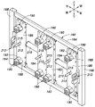
- a door member 160 is provided at the rear of the outer frame assembly 42.
- the door member 160 is located at a position corresponding to the upper edge of the upper housing 92 and the lower lateral member 162 extending horizontally behind the position corresponding to the lower edge of the lower housing 90 at the closed door position described later.
- the upper horizontal member 164 extending in the rear horizontal direction and the two left and right vertical members 166 and 168 connecting each end of the lower horizontal member 162 and the upper horizontal member 164 in the extending direction to each other. It is formed in a square frame shape, and the left vertical member 166 is attached to the left side member 44 by a hinge 170.
- the door member 160 has a closed door position facing the front surface of the lower housing 90 and the upper housing 92 around the pivot axis extending in the vertical direction of the hinge 170, and is shown in FIG. As shown above, it is rotatable between the closed door position and the open door position displaced rearward by approximately 90 degrees.
- the captured member 174 is attached to the right side member 44 by the mounting bracket 172.
- a capture member 176 is attached to the vertical member 168 on the right side. The capture member 176 engages with the captured member 174 so as to be detachably engaged when the door member 160 is in the closed door position, and holds the door member 160 in the closed door position.
- the left vertical member 166 extends in the vertical direction on the left outer side of the lower housing 90 and the upper housing 92 and on the right inner side of the left side member 44.
- the vertical member 168 on the right side extends in the vertical direction on the outer right side of the lower housing 90 and the upper housing 92 and on the inner left side of the side member 44 on the right side.
- the door member 160 extends in the vertical direction at a position corresponding to the left and right edges of the accommodation chamber 102 on the left side of the lower housing 90 and the upper housing 92, and the upper and lower ends thereof are the lower lateral member 162.
- Has a strip-shaped mounting member 184 and 186 extending in the vertical direction and having upper and lower ends coupled to the lower lateral member 162 and the upper lateral member 164.
- the advancing / retreating member 190 is directed toward each of the corresponding accommodation chambers 102 at the closed position of the door member 160 by the advancing / retreating guide pin 188 with a head. It is provided so that you can move forward and backward. In the closed position of the door member 160, the advancing / retreating direction of each advancing / retreating member 190 coincides with the front-rear direction of the accommodation chamber 102.
- Each advancing / retreating member 190 includes a base portion 192 including an engaging portion with the advancing / retreating guide pin 188 and a rubber abutting element 194 attached to the front portion of the base portion 192. As shown in FIG. 11, each advancing / retreating member 190 has a retracted position separated from the storage battery 150 housed in the corresponding storage chamber 102 at the closed position of the door member 160, and as shown in FIG. In addition, it is possible to move forward from the backward position and move forward and backward between the forward position and the forward position capable of contacting the storage battery 150 housed in the corresponding storage chamber 102.
- Each advancing / retreating member 190 is a portion other than the grip portion 150B of the storage battery 150 housed in the corresponding storage chamber 102 when the door member 160 is in the closed door position and is in the forward position, that is, the rear end surface of the storage battery main body 150A. Contact with.
- the mounting members 180, 182, 184, and 186 have translational members that translate in the vertical direction, which is a direction orthogonal to the advance / retreat direction of the advance / retreat member 190 for each advance / retreat member 190.
- 196 is provided.
- Each translation member 196 is formed with a stepped cam portion 196A.
- Each cam portion 196A engages with the stepped cam engaging portion 192A formed on the base portion 192 of the corresponding advancing / retreating member 190, and the translational movement of the advancing / retreating member 190 is changed to the advancing / retreating direction movement of the advancing / retreating member 190. It constitutes a conversion unit to be converted.
- the corresponding advancing / retreating member 190 moves in the advancing / retreating direction (front-back direction) due to the movement of each translation member 196 in the translation direction (vertical direction).
- the translational members 196 arranged above and below have two upper and lower link members (connected) in the shape of a plate including one end rotatably connected to each other by the pivot 198. Members) The other ends of the 200 and 202 are rotatably connected by the pivots 204 and 206.
- the upper and lower link members 200 and 202 form a toggle type link mechanism 208 which is a mechanical boosting (amplification) mechanism with the pivot 198 as a driving force input unit.
- the toggle type link mechanism 208 has two upper and lower link members 200 and 202 including one end rotatably connected to each other by the pivot 198.
- the other end of the upper link member 200 is rotatably connected to the upper translation member 196 which forms a slider by a pivot 204
- the other end of the lower link member 202 is the lower side which forms another slider. It is rotatably connected to the translation member 196 by the pivot 206. That is, the toggle type link mechanism 208 is provided to connect the translation members 196 located vertically adjacent to each other.
- the Axis 198 is adjacent to each other on the left and right, and is connected to each other by a manual handle 210.
- the handle 210 is an input member to which a driving force is input from the outside.
- the handle 210 forming the input portion is provided on the pivot axis 198 forming the connecting portion connecting the two link members 200 and 202 to each other.
- the toggle type link mechanism 208 mechanically connects the translation member 196 and the handle 210, and forms a transmission unit that transmits the driving force input to the handle 210 to the translation member 196.
- the translational member 196, the toggle linkage 208 and the handle 210 form a drive that moves the corresponding advancing / retreating member 190 between the retracted and forward positions.
- Each handle 210 is movable between a first position shown in FIG. 11 and a second position advanced in the advancing / retreating direction of the advancing / retreating member 190 from the first position shown in FIG. ,
- the corresponding advancing / retreating member 190 at the first position is positioned at the retracting position
- the corresponding advancing / retreating member 190 at the second position is positioned at the advancing position.
- the advancing / retreating member 190 is located in the retracted position when the handle 210 is in the first position, and is located in the forward position when the handle 210 is in the second position.
- the handle (input unit) 210 is provided so that the direction connecting the above-mentioned first position and the second position coincides with the advancing / retreating direction of the advancing / retreating member 190.
- the forward / backward moving directions of the advancing / retreating member 190 match the forward / backward moving directions of the handle 210, and the forward / backward operation of the advancing / retreating member 190 by the handle 210 becomes easy to understand and the operability is improved. ..
- the direction of the operating load by the handle 210 and the direction of the input load of the advancing / retreating member 190 to the rubber abutting element 194 are the same, and under the boosting (amplifying) action of the toggle type link mechanism 208, Even with a small operating load, the input load to the contact element 194 becomes large, and the contact element 194 is strongly pressed against the storage battery 150 in the accommodation chamber 102. As a result, the storage battery 150 in the storage chamber 102 is securely locked.
- guide pins 213 are connected to the support portions 211 at both ends of the handle 210.
- the guide pin 213 is slidably engaged in the axial direction with the corresponding cylindrical member 215 attached to the attachment members 180, 182, 184, 186. As a result, the movement of the handle 210 between the first position and the second position is surely performed without causing rattling.
- the link members 200 and 202 correspond to the pivot 198 as an apex.
- the link member 200 as shown in FIG. 12, is tilted in a chevron shape with respect to the mounting members 180, 182, 184, 186 and the handle 210 moves from the first position to the second position.
- 202 extends parallel to the corresponding mounting members 180, 182, 184, 186 and moves the translational member 196 to the forward position.
- the toggle type link mechanism 208 performs a boosting action when the translation member 196 moves from the retracted position to the forward position.
- a regulating device 212 is provided between the handle 210 and the corresponding mounting member 180 and 186 on one side.
- the restricting device 212 restricts the movement of the handle 210 to the first position when the handle 210 is located in the second position. As a result, the handle 210 is held in the second position, and the advancing / retreating member 190 is maintained in the advancing position.
- each storage battery 150 Since the storage battery 150 housed in each storage chamber 102 presses the surface located on the rear side toward the front by the abutting element 194 of the advancing / retreating member 190 held in the forward position, each storage battery 150 is In the accommodation chamber 102, the lower housing 90 and the upper housing 92 are securely fixed and held to the lower housing 90 and the upper housing 92 in a state where the forward movement is restricted by the wall surfaces of the lower housing 90 and the upper housing 92. As a result, the storage battery 150 housed in each storage chamber 102 is surely prevented from rattling due to vibration or the like, and the storage battery 150 in the contact-type electrical connection portion (not shown) in the lower housing 90 and the upper housing 92. The electrical connection of the battery does not become unstable.
- the handle 210 Since the handle 210 is mechanically connected by the translation member 196 via the toggle type link mechanism 208, the handle 210 is moved from the first position to the second position under the boosting action of the toggle type link mechanism 208.
- each advancing / retreating member 190 is strongly pressed against the corresponding storage battery main body 150A. That is, the operating force (driving force) input to the handle 210 is boosted and transmitted to the advancing / retreating member 190, and the operating force input to the handle 210 can be reduced.
- the prevention of the storage batteries 150 from coming out of the storage chamber 102 rearward can be reliably performed with good operability without requiring a large operating force.
- the above-mentioned state is maintained by the door member 160 being held in the closed door position by the engagement between the captured member 174 and the captured member 176, and the handle 210 being held in the second position by the regulating device 212.
- the door is maintained by the door member 160 being held in the closed door position by the engagement between the captured member 174 and the captured member 176, and the handle 210 being held in the second position by the regulating device 212. The door.
- the regulation operation by the regulation device 212 is released, the handle 210 is returned to the first position, the engagement between the captured member 126 and the capture member 128 is released, and the door member 160 is released. Is positioned at the open door position. As a result, all the storage batteries 150 housed in each storage chamber 102 can be taken out, and the work of taking out the storage batteries 150 can be performed with good operability.
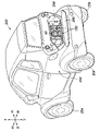
- FIG. 13 Another embodiment of the electric vehicle to which the article accommodating device according to the present invention is applied will be described with reference to FIG. 13
- the portion corresponding to FIG. 1 is designated by the same reference numeral as that shown in FIG. 1, and the description thereof will be omitted.
- the electric vehicle 250 has a vehicle body 252, left and right front wheels 254, and left and right rear wheels 256, and the rear wheels 256 are provided by an electric motor (not shown) mounted on the vehicle body 252. It is a four-wheel electric vehicle that is driven to rotate.
- a storage battery chamber 258 that opens toward the rear is provided, and a rear lid 260 that opens and closes the storage battery chamber 258 by rotatably attaching the lower end to the vehicle body 252 around the horizontal axis is provided.
- the storage battery chamber 258 is provided with a storage battery accommodating device (article accommodating device) 40.
- the storage battery accommodating device 40 is that of the first embodiment described above. The same effect as that of the above-described embodiment can be obtained in this embodiment as well.
- the storage battery chamber 258 may be provided with the storage battery accommodating device 40 of the above-described second embodiment instead of the storage battery accommodating device 40 of the first embodiment.
- FIG. 13 Another embodiment of the electric vehicle to which the article accommodating device according to the present invention is applied will be described with reference to FIG. 13
- the portion corresponding to FIG. 1 is designated by the same reference numeral as that shown in FIG. 1, and the description thereof will be omitted.
- the electric vehicle 250 has a vehicle body 252, left and right front wheels 254, and left and right rear wheels 256, and the rear wheels 256 are provided by an electric motor (not shown) mounted on the vehicle body 252. It is a four-wheel electric vehicle that is driven by rotation.
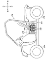
- FIG. 14 Another embodiment of the electric vehicle to which the article accommodating device according to the present invention is applied will be described with reference to FIG. 14, the portion corresponding to FIG. 1 is designated by the same reference numeral as that shown in FIG. 1, and the description thereof will be omitted.
- the electric vehicle 270 has a vehicle body 272, left and right front wheels 274, and left and right rear wheels 276, and the rear wheels 276 are provided by an electric motor (not shown) mounted on the vehicle body 272. It is a four-wheel electric vehicle that is driven by rotation.
- a storage battery accommodating device (article accommodating device) 40 is provided below the driver's seat 278.
- the storage battery accommodating device 40 is arranged sideways so that the storage battery 150 can be taken in and out from the side of the vehicle body 272. Other than this, it is substantially the same as the above-described embodiment, and the same effect as that of the above-mentioned embodiment can be obtained in this embodiment as well.
- the storage battery accommodating device 40 of the above-described second embodiment may be provided below the driver's seat 278 instead of the storage battery accommodating device 40 of the first embodiment.
- the number of stages of the accommodation chamber 102 and the number of arrangements of each stage are not limited to two, and may be one or three or more.
- the number of stages of the accommodation chamber 102 and the number of arrangements of each stage may be different from each other.
- the door members 110 and 160 may be electric rather than manual.
- the driving force input to the input unit may be a power device such as an electric motor, not manually.
- the storage battery accommodating device 40 may be a storage battery accommodating device in a charging device, a power supply device, or the like.
- the power storage device housed in the storage battery storage device 40 may be a power storage device having a power storage unit by a chemical reaction, or may be a power storage device such as a capacitor.
- the article accommodating device according to the present invention is not limited to the storage battery accommodating device 40 accommodating the storage battery, and may be a device accommodating articles other than the storage battery 150.
Landscapes
- Engineering & Computer Science (AREA)
- Mechanical Engineering (AREA)
- Chemical & Material Sciences (AREA)
- Chemical Kinetics & Catalysis (AREA)
- Electrochemistry (AREA)
- General Chemical & Material Sciences (AREA)
- Combustion & Propulsion (AREA)
- Transportation (AREA)
- Aviation & Aerospace Engineering (AREA)
- Battery Mounting, Suspending (AREA)
Priority Applications (1)
| Application Number | Priority Date | Filing Date | Title |
|---|---|---|---|
| JP2022556987A JP7812339B2 (ja) | 2020-10-14 | 2021-10-12 | 物品収容装置 |
Applications Claiming Priority (4)
| Application Number | Priority Date | Filing Date | Title |
|---|---|---|---|
| JP2020173283 | 2020-10-14 | ||
| JP2020-173283 | 2020-10-14 | ||
| JP2021038510 | 2021-03-10 | ||
| JP2021-038510 | 2021-03-10 |
Publications (1)
| Publication Number | Publication Date |
|---|---|
| WO2022080344A1 true WO2022080344A1 (ja) | 2022-04-21 |
Family
ID=81208218
Family Applications (1)
| Application Number | Title | Priority Date | Filing Date |
|---|---|---|---|
| PCT/JP2021/037660 Ceased WO2022080344A1 (ja) | 2020-10-14 | 2021-10-12 | 物品収容装置 |
Country Status (2)
| Country | Link |
|---|---|
| JP (1) | JP7812339B2 (https=) |
| WO (1) | WO2022080344A1 (https=) |
Citations (4)
| Publication number | Priority date | Publication date | Assignee | Title |
|---|---|---|---|---|
| JPS57195761U (https=) * | 1981-06-05 | 1982-12-11 | ||
| JP2003178733A (ja) * | 2001-12-07 | 2003-06-27 | Fuji Photo Film Co Ltd | 電池の接点構造 |
| EP1531086A1 (en) * | 2003-11-17 | 2005-05-18 | Petrus Wilhelmus Maria Beks | Improved storage unit with drawers for vehicles and vessels with a flat cargo floor |
| WO2020085293A1 (ja) * | 2018-10-22 | 2020-04-30 | 本田技研工業株式会社 | 移動体 |
Family Cites Families (3)
| Publication number | Priority date | Publication date | Assignee | Title |
|---|---|---|---|---|
| JP4720150B2 (ja) | 2004-11-12 | 2011-07-13 | 株式会社Gsユアサ | 組電池 |
| JP5933344B2 (ja) | 2012-05-31 | 2016-06-08 | 三洋電機株式会社 | 電源装置 |
| CN105705408A (zh) * | 2013-11-06 | 2016-06-22 | 雅马哈发动机株式会社 | 骑乘式电动车 |
-
2021
- 2021-10-12 WO PCT/JP2021/037660 patent/WO2022080344A1/ja not_active Ceased
- 2021-10-12 JP JP2022556987A patent/JP7812339B2/ja active Active
Patent Citations (4)
| Publication number | Priority date | Publication date | Assignee | Title |
|---|---|---|---|---|
| JPS57195761U (https=) * | 1981-06-05 | 1982-12-11 | ||
| JP2003178733A (ja) * | 2001-12-07 | 2003-06-27 | Fuji Photo Film Co Ltd | 電池の接点構造 |
| EP1531086A1 (en) * | 2003-11-17 | 2005-05-18 | Petrus Wilhelmus Maria Beks | Improved storage unit with drawers for vehicles and vessels with a flat cargo floor |
| WO2020085293A1 (ja) * | 2018-10-22 | 2020-04-30 | 本田技研工業株式会社 | 移動体 |
Also Published As
| Publication number | Publication date |
|---|---|
| JP7812339B2 (ja) | 2026-02-09 |
| JPWO2022080344A1 (https=) | 2022-04-21 |
Similar Documents
| Publication | Publication Date | Title |
|---|---|---|
| WO2020017324A1 (ja) | 物品収容装置及び電動車両 | |
| KR101637820B1 (ko) | 차량용 리트랙터블 핸들 장치 | |
| EP1025961B1 (en) | Battery powered hand guided power tool | |
| CN114435487B (zh) | 翻盖致动组件及包括其的加油口或充电口翻盖组件 | |
| US11555339B2 (en) | Lock device | |
| US20050285410A1 (en) | Convertible top latch | |
| CN101764270A (zh) | 充电口装置 | |
| JP7621945B2 (ja) | 保持装置 | |
| KR20230075226A (ko) | 차량용 프론트리드 래치장치 | |
| US20150247346A1 (en) | Locking lever and vehicle door opening-closing device | |
| CN217453867U (zh) | 工具箱系统 | |
| US20230112102A1 (en) | Hydrogen tank-loaded vehicle | |
| WO2022080344A1 (ja) | 物品収容装置 | |
| CN113715740A (zh) | 负载载架 | |
| WO2024241372A1 (ja) | 車両の前部構造 | |
| CN113199987B (zh) | 车辆用收纳装置 | |
| US11713086B2 (en) | Latch mechanism | |
| US12570245B2 (en) | Vehicle battery attachment/detachment device | |
| US20240400296A1 (en) | Article storage device | |
| CN211442147U (zh) | 一种轮式传动的手套箱锁止装置 | |
| CN116922337A (zh) | 工具箱系统 | |
| JP2023042475A (ja) | リッド装置 | |
| JP7609089B2 (ja) | 車両用ドアハンドル装置 | |
| US20220305897A1 (en) | Vehicle | |
| KR102442013B1 (ko) | 차량 및 차량의 내장품 설치방법 |
Legal Events
| Date | Code | Title | Description |
|---|---|---|---|
| 121 | Ep: the epo has been informed by wipo that ep was designated in this application |
Ref document number: 21880083 Country of ref document: EP Kind code of ref document: A1 |
|
| ENP | Entry into the national phase |
Ref document number: 2022556987 Country of ref document: JP Kind code of ref document: A |
|
| WWE | Wipo information: entry into national phase |
Ref document number: 202347031716 Country of ref document: IN |
|
| NENP | Non-entry into the national phase |
Ref country code: DE |
|
| 122 | Ep: pct application non-entry in european phase |
Ref document number: 21880083 Country of ref document: EP Kind code of ref document: A1 |