WO2022080182A1 - トナー搬送装置およびそれを備えたクリーニング装置並びに画像形成装置 - Google Patents
トナー搬送装置およびそれを備えたクリーニング装置並びに画像形成装置 Download PDFInfo
- Publication number
- WO2022080182A1 WO2022080182A1 PCT/JP2021/036782 JP2021036782W WO2022080182A1 WO 2022080182 A1 WO2022080182 A1 WO 2022080182A1 JP 2021036782 W JP2021036782 W JP 2021036782W WO 2022080182 A1 WO2022080182 A1 WO 2022080182A1
- Authority
- WO
- WIPO (PCT)
- Prior art keywords
- toner
- brush
- transfer device
- transport screw
- transport
- Prior art date
- Legal status (The legal status is an assumption and is not a legal conclusion. Google has not performed a legal analysis and makes no representation as to the accuracy of the status listed.)
- Ceased
Links
Images


Classifications
-
- G—PHYSICS
- G03—PHOTOGRAPHY; CINEMATOGRAPHY; ANALOGOUS TECHNIQUES USING WAVES OTHER THAN OPTICAL WAVES; ELECTROGRAPHY; HOLOGRAPHY
- G03G—ELECTROGRAPHY; ELECTROPHOTOGRAPHY; MAGNETOGRAPHY
- G03G15/00—Apparatus for electrographic processes using a charge pattern
- G03G15/06—Apparatus for electrographic processes using a charge pattern for developing
- G03G15/08—Apparatus for electrographic processes using a charge pattern for developing using a solid developer, e.g. powder developer
- G03G15/0822—Arrangements for preparing, mixing, supplying or dispensing developer
- G03G15/0887—Arrangements for conveying and conditioning developer in the developing unit, e.g. agitating, removing impurities or humidity
- G03G15/0891—Arrangements for conveying and conditioning developer in the developing unit, e.g. agitating, removing impurities or humidity for conveying or circulating developer, e.g. augers
-
- G—PHYSICS
- G03—PHOTOGRAPHY; CINEMATOGRAPHY; ANALOGOUS TECHNIQUES USING WAVES OTHER THAN OPTICAL WAVES; ELECTROGRAPHY; HOLOGRAPHY
- G03G—ELECTROGRAPHY; ELECTROPHOTOGRAPHY; MAGNETOGRAPHY
- G03G15/00—Apparatus for electrographic processes using a charge pattern
- G03G15/06—Apparatus for electrographic processes using a charge pattern for developing
- G03G15/08—Apparatus for electrographic processes using a charge pattern for developing using a solid developer, e.g. powder developer
- G03G15/0822—Arrangements for preparing, mixing, supplying or dispensing developer
- G03G15/0887—Arrangements for conveying and conditioning developer in the developing unit, e.g. agitating, removing impurities or humidity
- G03G15/0889—Arrangements for conveying and conditioning developer in the developing unit, e.g. agitating, removing impurities or humidity for agitation or stirring
-
- G—PHYSICS
- G03—PHOTOGRAPHY; CINEMATOGRAPHY; ANALOGOUS TECHNIQUES USING WAVES OTHER THAN OPTICAL WAVES; ELECTROGRAPHY; HOLOGRAPHY
- G03G—ELECTROGRAPHY; ELECTROPHOTOGRAPHY; MAGNETOGRAPHY
- G03G21/00—Arrangements not provided for by groups G03G13/00 - G03G19/00, e.g. cleaning, elimination of residual charge
- G03G21/0005—Arrangements not provided for by groups G03G13/00 - G03G19/00, e.g. cleaning, elimination of residual charge for removing solid developer or debris from the electrographic recording medium
- G03G21/0011—Arrangements not provided for by groups G03G13/00 - G03G19/00, e.g. cleaning, elimination of residual charge for removing solid developer or debris from the electrographic recording medium using a blade; Details of cleaning blades, e.g. blade shape, layer forming
- G03G21/0017—Details relating to the internal structure or chemical composition of the blades
-
- G—PHYSICS
- G03—PHOTOGRAPHY; CINEMATOGRAPHY; ANALOGOUS TECHNIQUES USING WAVES OTHER THAN OPTICAL WAVES; ELECTROGRAPHY; HOLOGRAPHY
- G03G—ELECTROGRAPHY; ELECTROPHOTOGRAPHY; MAGNETOGRAPHY
- G03G21/00—Arrangements not provided for by groups G03G13/00 - G03G19/00, e.g. cleaning, elimination of residual charge
- G03G21/0005—Arrangements not provided for by groups G03G13/00 - G03G19/00, e.g. cleaning, elimination of residual charge for removing solid developer or debris from the electrographic recording medium
- G03G21/0035—Arrangements not provided for by groups G03G13/00 - G03G19/00, e.g. cleaning, elimination of residual charge for removing solid developer or debris from the electrographic recording medium using a brush; Details of cleaning brushes, e.g. fibre density
-
- G—PHYSICS
- G03—PHOTOGRAPHY; CINEMATOGRAPHY; ANALOGOUS TECHNIQUES USING WAVES OTHER THAN OPTICAL WAVES; ELECTROGRAPHY; HOLOGRAPHY
- G03G—ELECTROGRAPHY; ELECTROPHOTOGRAPHY; MAGNETOGRAPHY
- G03G21/00—Arrangements not provided for by groups G03G13/00 - G03G19/00, e.g. cleaning, elimination of residual charge
- G03G21/10—Collecting or recycling waste developer
- G03G21/105—Arrangements for conveying toner waste
-
- G—PHYSICS
- G03—PHOTOGRAPHY; CINEMATOGRAPHY; ANALOGOUS TECHNIQUES USING WAVES OTHER THAN OPTICAL WAVES; ELECTROGRAPHY; HOLOGRAPHY
- G03G—ELECTROGRAPHY; ELECTROPHOTOGRAPHY; MAGNETOGRAPHY
- G03G2221/00—Processes not provided for by group G03G2215/00, e.g. cleaning or residual charge elimination
- G03G2221/16—Mechanical means for facilitating the maintenance of the apparatus, e.g. modular arrangements and complete machine concepts
- G03G2221/1618—Mechanical means for facilitating the maintenance of the apparatus, e.g. modular arrangements and complete machine concepts for the cleaning unit
- G03G2221/1624—Mechanical means for facilitating the maintenance of the apparatus, e.g. modular arrangements and complete machine concepts for the cleaning unit transporting cleaned toner into separate vessels, e.g. photoreceptors, external containers
Definitions
- the present invention relates to a toner transfer device for transporting waste toner removed from the surface of an image carrier and toner supplied to a developing device, a cleaning device provided with the toner transfer device, and an image forming device.
- a powder developer (hereinafter referred to as toner) is mainly used, and an electrostatic structure formed on an image carrier such as a photoconductor drum is used.
- a general process is to visualize a latent image with toner in a developing device, transfer the toner image onto a recording medium, and then perform fixing processing.
- a cleaning apparatus for removing residual toner on the surface of the photoconductor drum is mounted.
- the waste toner collected from the surface of the drum has uneven adhesion and particle size of the external additive due to mechanical stress, and further, paper dust and the like are mixed in to deteriorate the fluidity. It is easy to solidify.
- the fluidity of the toner tends to decrease due to the high temperature environment. Therefore, there is a problem that waste toner having reduced fluidity is solidified around the transport screw (for example, between spiral blades) in a high temperature and high humidity environment, resulting in a so-called blocking state, which makes transport difficult.
- Patent Documents 1 and 2 disclose a method of bringing a film-shaped flicker into contact with a transport screw to suppress the adhesion of toner to the transport screw. ing. Further, Patent Document 3 proposes a method of bringing the brush member into contact with the rotating shaft and the blade of the transport screw.
- Japanese Unexamined Patent Publication No. 2002-278401 Japanese Unexamined Patent Publication No. 2006-343371 Japanese Unexamined Patent Publication No. 2007-147733
- Patent Documents 1 and 2 have a problem that toner adheres between the flicker and the portion where the flicker is lifted by the blades of the transport screw, and the toner transport performance is deteriorated.
- the specifications of the brush described in Patent Document 3 are that the material is polypropylene and the fiber density is 15,000 / inch 2 , which is relatively high. With such a high-density brush, it becomes difficult for toner that has entered from above the brush to pass through the brush, and the brush blocks the toner. Further, if the toner is left in a high temperature and high humidity environment with the toner inserted between the fibers of the brush, the toner adheres to the brush, and there is a problem that the effect of removing the toner by the brush cannot be obtained.
- an object of the present invention is to provide a toner transfer device capable of effectively preventing solidification of toner and maintaining stable toner transfer performance, a cleaning device provided with the toner transfer device, and an image forming device. There is.
- the first configuration of the present invention is a toner transport device including a toner transport path for transporting toner, a transport screw, and a brush member.
- the transport screw has a rotary shaft rotatably arranged inside the toner transport path, and spiral blades formed on the outer peripheral surface of the rotary shaft.
- the brush member a large number of brush bristles that abut on the outer peripheral surface of the transport screw and swing are planted at predetermined intervals along the axial direction of the transport screw.
- the brush bristles planted at one place are composed of one to three fibers, and the brush bristles are planted in parallel with each other at regular intervals of 0.5 to 3 mm.
- a brush member in which waste toner is disintegrated by rocking to suppress aggregation and solidification is formed, and brush bristles planted in one place are composed of one to three fibers.
- the brush bristles By constructing the brush bristles to be planted in parallel with each other at regular intervals of 0.5 to 3 mm, the waste toner conveyed by the transfer screw is not blocked by the brush member, and even in a high temperature and high humidity environment. Since the waste toner does not adhere to the brush bristles, the cleaning performance of the transport screw by the brush member can be maintained for a long period of time.
- FIG. 1 Schematic cross-sectional view showing the internal configuration of the image forming apparatus 100 including the cleaning apparatus 7a to 7d of the present invention.
- Partially enlarged view of the vicinity of the image forming portion Pa in FIG. A side sectional view showing a configuration in the vicinity of the cleaning device 7a according to the first embodiment of the present invention.
- Partial enlarged view of the transport screw 29 and the brush member 30 of the cleaning device 7a of the first embodiment as viewed from the radial direction.
- Cross-sectional view of the transport screw 29 and the brush member 30 of the cleaning device 7a of the first embodiment as viewed from the axial direction.
- Partial enlarged view of the transfer screw 29 and the brush member 30 used in the cleaning device 7a according to the second embodiment of the present invention as viewed from the radial direction.
- Partial enlarged view of the transport screw 29, the brush member 30, and the flicker 31 of the cleaning device 7a of the third embodiment as viewed from the radial direction.
- Cross-sectional view of the transport screw 29, the brush member 30, and the flicker 31 of the cleaning device 7a of the third embodiment as viewed from the axial direction. It is a partial cross-sectional view including the toner supply part 40 of the developing apparatus 3a, and is the figure which shows the example which arranges the brush member 30 in the horizontal transport part 42 of the toner supply part 40.
- FIG. 1 is a schematic cross-sectional view of an image forming apparatus 100 equipped with the cleaning apparatus 7a to 7d of the present invention.
- the main body of the image forming apparatus 100 four image forming portions Pa, Pb, Pc and Pd are arranged in order from the upstream side in the transport direction (left side in FIG. 1).
- These image forming portions Pa to Pd are provided corresponding to images of four different colors (magenta, cyan, yellow, and black).
- the image forming units Pa to Pd sequentially form magenta, cyan, yellow, and black images by each step of charging, exposure, development, and transfer.
- Photoreceptor drums 1a, 1b, 1c and 1d carrying visible images (toner images) of each color are arranged in these image forming portions Pa to Pd. Further, in FIG. 1, an intermediate transfer belt 8 that rotates in the counterclockwise direction is provided adjacent to each image forming portion Pa to Pd.
- the toner images formed on the photoconductor drums 1a to 1d are sequentially transferred onto the intermediate transfer belt 8 that moves while abutting on the photoconductor drums 1a to 1d. After that, the toner image transferred on the intermediate transfer belt 8 is transferred at once on the paper S as an example of the recording medium by the secondary transfer roller 9.
- the toner image is fixed on the paper S in the fixing portion 13, the toner image is discharged from the image forming apparatus 100 main body.
- the image forming process for each of the photoconductor drums 1a to 1d is executed while rotating the photoconductor drums 1a to 1d in the clockwise direction in FIG.
- the paper S on which the toner image is transferred is housed in a paper cassette 16 arranged at the lower part of the image forming apparatus 100.
- the paper S is conveyed to the secondary transfer roller 9 via the paper feed roller 12a and the resist roller pair 12b.
- the main motor (not shown) first starts the rotation of the photoconductor drums 1a to 1d. Then, the surfaces of the photoconductor drums 1a to 1d are uniformly charged by the charging rollers 21 (see FIG. 2) of the charging devices 2a to 2d. Next, the surfaces of the photoconductor drums 1a to 1d are irradiated with light by the beam light (laser light) emitted from the exposure apparatus 5, and an electrostatic latent image corresponding to the image signal is formed on the photoconductor drums 1a to 1d.
- the beam light laser light
- the developing devices 3a to 3d are filled with a predetermined amount of toner of each color of magenta, cyan, yellow and black, respectively.
- the toner containers 4a to 4d to the developing devices 3a to 3d are used. Toner is replenished.
- the toner in the developer is supplied onto the photoconductor drums 1a to 1d by the developing rollers 25 (see FIG. 2) of the developing devices 3a to 3d, and is electrostatically adhered to the photoconductor drums 1a to 1d. As a result, a toner image corresponding to the electrostatic latent image formed by the exposure from the exposure apparatus 5 is formed.
- an electric field is applied between the primary transfer rollers 6a to 6d and the photoconductor drums 1a to 1d at a predetermined transfer voltage by the primary transfer rollers 6a to 6d, and magenta, cyan, yellow and magenta, cyan, yellow and magenta on the photoconductor drums 1a to 1d are applied.
- the black toner image is primarily transferred onto the intermediate transfer belt 8.
- These four-color images are formed with a predetermined positional relationship predetermined for forming a predetermined full-color image.
- the toner remaining on the surfaces of the photoconductor drums 1a to 1d is removed by the cleaning blades 28 (see FIG. 2) of the cleaning devices 7a to 7d in preparation for the subsequent formation of a new electrostatic latent image.
- the paper S is adjacent to the intermediate transfer belt 8 from the resist roller pair 12b at a predetermined timing.
- the full-color image is transferred to the secondary transfer roller 9 provided in the above.
- the paper S on which the toner image is transferred is conveyed to the fixing unit 13.
- the toner remaining on the surface of the intermediate transfer belt 8 is removed by the belt cleaning unit 19.
- the paper S conveyed to the fixing portion 13 is heated and pressurized by the fixing roller pair 13a to fix the toner image on the surface of the paper S, and a predetermined full-color image is formed.
- the paper S on which the full-color image is formed is discharged by the discharge roller pair 15 as it is (or after being sent to the double-sided transport path 18 and printed on both sides) after the transport directions are sorted by the branch portions 14 branched in a plurality of directions. It is discharged to the tray 17.
- FIG. 2 is an enlarged view of the vicinity of the image forming portion Pa in FIG.
- FIG. 3 is a side sectional view showing a configuration around the cleaning device 7a according to the first embodiment of the present invention in FIG.
- the image forming unit Pa including the photoconductor drum 1a, the charging device 2a, and the cleaning device 7a will be described in detail, but since the image forming units Pb to Pd also have the same configuration, the description thereof will be omitted.
- a charging device 2a, a developing device 3a, and a cleaning device 7a are arranged around the photoconductor drum 1a along the drum rotation direction (clockwise direction in FIG. 2), and an intermediate transfer belt 8 is provided.
- the primary transfer roller 6a is arranged so as to sandwich the.
- a belt cleaning unit 19 facing the tension roller 11 with the intermediate transfer belt 8 interposed therebetween is arranged on the upstream side of the intermediate transfer belt 8 in the rotation direction with respect to the photoconductor drum 1a.
- the photoconductor drum 1a has a photosensitive layer laminated on the outer peripheral surface of an aluminum drum tube.
- a photosensitive layer for example, an organic photosensitive layer (OPC) using an organic photoconductor or an inorganic photosensitive layer such as an amorphous silicon (a—Si) photosensitive layer formed by vapor deposition of silane gas or the like is used.
- OPC organic photosensitive layer
- a—Si amorphous silicon
- the charging device 2a has a charging roller 21 that contacts the photoconductor drum 1a and applies a charging bias to the drum surface, and a brush roller 22 for cleaning the charging roller 21.
- the developing device 3a has two stirring and transporting members including a stirring and transporting screw 23 and a supply and transporting screw 24 in the developing container 20, and a developing roller 25, and the toner carried on the surface of the developing roller 26 is a photoconductor.
- the electrostatic latent image is developed into a toner image by flying to the surface of the drum 1a.
- the cleaning device 7a (toner transfer device) includes a housing 26 (toner transfer path), a rubbing roller 27, a cleaning blade 28, a transfer screw 29, and a brush member 30.
- the housing 26 has an opening facing the photoconductor drum 1a, and houses a rubbing roller 27, a cleaning blade 28, a transport screw 29, and a brush member 30.
- the rubbing roller 27 is in contact with the surface (outer peripheral surface) of the photoconductor drum 1a via the opening of the housing 26.
- the rubbing roller 27 is rotatably supported by a side plate (not shown) in the front-rear direction (direction perpendicular to the paper surface of FIG. 3) of the housing 26.
- the rubbing roller 27 is rotationally driven in the same direction (with direction) on the contact surface with the photoconductor drum 1a by a driving means (not shown). As a result, the residual toner on the surface of the photoconductor drum 1a is removed, and the surface of the photoconductor drum 1a is rubbed and polished.
- the linear velocity of the rubbing roller 27 is controlled to be faster than the linear velocity of the photoconductor drum 1a (for example, 1.2 times).
- Examples of the rubbing roller 27 include a structure in which a foam layer made of EPDM rubber and having an Asuka C hardness of 55 ° is formed around a metal shaft as a roller body.
- the material of the roller body is not limited to EPDM rubber, and rubber of other materials or foamed rubber body may be used, and those having an Asuka C hardness in the range of 10 to 90 ° are preferably used.
- the cleaning blade 28 abuts on the photoconductor drum 1a on the downstream side of the contact portion between the photoconductor drum 1a and the rubbing roller 27 with respect to the rotation direction of the photoconductor drum 1a (clockwise direction in FIG. 3).
- the cleaning blade 28 for example, a blade made of polyurethane rubber having a JIS hardness of 78 ° and a thickness of 2 mm is used.
- the material and hardness of the cleaning blade 28, the dimensions, the mounting angle to the photoconductor drum 1a, the biting amount, the pressure contact force, and the like are appropriately set according to the specifications of the photoconductor drum 1a.
- the transport screw 29 is arranged below in the housing 26, and has a rotary shaft 29a and a spiral transport blade 29b integrally formed on the outer peripheral surface of the rotary shaft 29a (both see FIG. 4).
- the rotary shaft 29a is rotatably supported by a side plate in the front-rear direction of the housing 26.
- the waste toner scraped off from the photoconductor drum 1a by the rubbing roller 27 and the cleaning blade 28 and staying in the housing 26 is axially conveyed along with the rotation of the conveying screw 29 and discharged to the outside of the cleaning device 7a. Toner.
- the brush member 30 is arranged between the housing 26 of the cleaning device 7 and the transport screw 29. As shown in FIG. 3, one end of the brush member 30 is fixed to the inner wall surface of the housing 26, and the other end becomes a free end and extends to a position where it comes into contact with the transport screw 29.
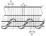
- FIG. 4 is a partially enlarged view of the transport screw 29 and the brush member 30 of the cleaning device 7a of the first embodiment as viewed from the radial direction (perpendicular to the rotating shaft 29a).
- the brush member 30 has a ribbon-shaped base material portion 30a extending along the axial direction of the transport screw 29 (left-right direction in FIG. 4) and a large number of brushes planted at equal intervals in the longitudinal direction of the base material portion 30a. It is composed of hair 30b.
- the brush bristles 30b project vertically from the base material portion 30a with respect to the rotation shaft 29a of the transfer screw 29.
- the brush bristles 30b overlap with the rotating shaft 29a and the transport blade 29b of the transport screw 29, and the tip portion extends to a position beyond the rotary shaft 29a.
- FIG. 5 is a cross-sectional view of the transport screw 29 and the brush member 30 of the cleaning device 7a of the first embodiment as viewed from the axial direction.
- the brush bristles 30b are pushed down by the transport blades 29b and elastically deformed as the transport screw 29 rotates (solid line in FIG. 5), and are in contact with the rotating shaft 29a due to the restoring force (broken line in FIG. 5).
- the brush bristles 30b swing between the inner surface of the housing 26 and the transport screw 29 by repeatedly reciprocating. As a result, the stagnant toner around the transport screw 29 is disentangled at the tip of the brush bristles 30b and moved by the transport screw 29 without solidifying, so that the waste toner in the housing 26 is efficiently transported to the outside.
- One bundle of brush bristles 30b is composed of 1 to 3 fibers made of synthetic resin.
- the thickness of the fiber is about 0.1 to 0.4 mm.
- the distance (pitch) X of the brush bristles 30b in the direction of the rotation axis 29a is 0.5 to 3 mm. That is, the brush member 30 used in the present embodiment has a significantly lower density of brush bristles 30b than in the conventional case. With this configuration, the waste toner conveyed by the transfer screw 29 is not blocked by the brush member 30, and the waste toner does not adhere to the brush bristles 30b even in a high temperature and high humidity environment. Therefore, the cleaning performance of the transport screw 29 by the brush member 30 can be maintained for a long period of time.
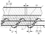
- FIG. 6 is a partially enlarged view of the transport screw 29 and the brush member 30 used in the cleaning device 7a according to the second embodiment of the present invention as viewed from the radial direction.
- the brush bristles 30b of the brush member 30 are not perpendicular to the rotation axis 29a, but are planted on the base material portion 30a at a predetermined angle.
- the configuration of the other parts is the same as that of the first embodiment.
- the angle ⁇ of the brush bristles 30b with respect to the surface S perpendicular to the rotation axis 29a is P1 when the points where the same brush bristles 30b come into contact with the rotation axis 29a and the spiral blades 29b are P1 and P2, respectively.
- the axial distance Y of P2 is set to be larger than the pitch X of the brush bristles 30b.
- the brush bristles 30b come into contact with the entire area of the rotary shaft 29a of the transport screw 29 and the outer peripheral surface of the spiral blade 29b in the axial direction evenly (evenly), so that waste toner can be efficiently solved. Further, since the brush bristles 30b are present at a constant height from the rotation shaft 29a even in a place where the brush bristles 30b are not in contact with each other, adhesion of toner in the height direction (diameter direction) can be suppressed.
- FIG. 7 is a side sectional view showing a configuration around the cleaning device 7a according to the third embodiment of the present invention.
- FIG. 8 is a partially enlarged view of the transport screw 29, the brush member 30, and the flicker 31 of the cleaning device 7a of the third embodiment as viewed from the radial direction.
- FIG. 9 is a cross-sectional view of the transport screw 29, the brush member 30, and the flicker 31 of the cleaning device 7a of the third embodiment as viewed from the axial direction.
- the flicker 31 is indicated by a dotted line in FIG.
- the flicker 31 is arranged on the side opposite to the brush member 30 (on the side of the rubbing roller 27) with the transport screw 29 interposed therebetween.
- the configuration of other parts of the cleaning device 7a is the same as that of the second embodiment.
- the flicker 31 is a film-like member extending over the entire axial direction of the transport screw 29 (direction perpendicular to the paper surface in FIG. 7), and one end in the width direction orthogonal to the longitudinal direction is inside the housing 26. It is fixed at a position overlapping with the brush member 30 on the wall surface, and the other end thereof becomes a free end and extends to a position where it comes into contact with the transport screw 29. Further, a large number of scraping pieces 31a are formed at a predetermined pitch on the free end side, and come into contact with the outer peripheral surface of the transport screw 29 from the side opposite to the brush bristles 30b. The scraping pieces 31a are formed perpendicular to the rotation shaft 29a of the transport screw 29 at regular intervals larger than the pitch of the brush bristles 30b.
- the material of the flicker 31 is not particularly limited as long as it is an elastic material that swings in contact with the spiral blade 29b of the transport screw 29.
- a polyethylene terephthalate (PET) sheet Limirror (registered trademark) sheet
- Teflon Various synthetic resin sheets having low frictional resistance such as (registered trademark) sheet and Kapton can be used, but the helix sheet is preferable from the viewpoint of cost and durability.
- the flicker 31 is lifted by the spiral blade 29b and elastically deformed as the transport screw 29 rotates (solid line in FIG. 9), and is in contact with the rotating shaft 29a due to the restoring force (dashed line in FIG. 9).
- the scraping piece 31a swings between the transport screw 29 and the rubbing roller 27 by repeatedly reciprocating. As a result, the accumulated toner near the lower part of the rubbing roller 27 is dissolved at the tip of the scraping piece 31a and moves to the periphery of the transport screw 29 without solidifying, so that the waste toner in the housing 26 is efficiently transported to the outside. Will be done.
- the toner adhesion to the transport screw 29 is more effective than in the first and second embodiments. Can be suppressed.
- the rubbing roller 27 has a function of interposing a toner containing an abrasive between the rubbing roller 27 and the photoconductor drum 1a to polish the surface of the photoconductor drum 1a. Also has. Therefore, the toner tends to stay in the vicinity of the contact portion between the rubbing roller 27 and the photoconductor drum 1a, but the flicker 31 is used to prevent the toner around the rubbing roller 27 from aggregating and solidifying. As a result, the toner used for polishing the surface of the photoconductor drum 1a can be efficiently replaced, and the polishing effect is also improved.
- the length, width, and thickness of the flicker 31 and the size and pitch of the scraping piece 31a are not particularly limited, and may be appropriately set according to the outer diameter and pitch of the transport screw 29. Further, although the brush member 30 is arranged between the transfer screw 29 and the housing 26 and the flicker 31 is arranged above the transfer screw 29, the arrangement of the brush member 30 and the flicker 31 may be reversed.
- the present invention is not limited to each of the above embodiments, and various modifications can be made without departing from the spirit of the present invention.
- the configuration of the present invention is, for example, only the rubbing roller 27.
- the present invention is not limited to the cleaning devices 7a to 7d, but the waste toner transport section for transporting the waste toner from the cleaning devices 7a to 7d to the waste toner collection container, and the toner from the toner containers 4a to 4d to the developing devices 3a to 3d. It can be applied to various toner transfer devices such as a toner replenishment unit for replenishment.
- FIG. 10 shows an example in which the present invention is applied to the toner supply path to the developing devices 3a to 3d.
- FIG. 10 is a partial cross-sectional view including the toner replenishment unit 40 (toner transfer device) of the developing device 3a.
- the toner replenishment unit 40 is perpendicular to the vertical transfer unit 41 that vertically conveys (drops) the toner supplied from the toner container 4a (see FIG. 1) through the toner replenishment port 40a. It has a horizontal transport unit 42 (toner transport path) that transports the toner delivered from the transport unit 41 in the horizontal direction.
- the rotating shaft 23a of the stirring transfer screw 23 extends into the horizontal transfer section 42.
- a replenishment blade 23c is integrally formed in a portion of the rotating shaft 23a of the stirring transfer screw 23 arranged in the horizontal transfer portion 42.
- the replenishment blade 23c is formed by spiral blades facing in the same direction as the transport blade 23b (with the same winding direction), and is formed with a smaller pitch and a smaller diameter than the transport blade 23b.
- a brush member 30 is arranged in the horizontal transport portion 42.
- the brush member 30 is arranged between the developing container 20 of the developing device 3a and the stirring transfer screw 23 (replenishment blade 23c).
- One end of the brush member 30 is fixed to the inner wall surface of the developing container 20, and the other end becomes a free end and extends to a position where it comes into contact with the supply blade 23c of the stirring transfer screw 23.
- the number, thickness, spacing (pitch), etc. of the brush bristles 30b of the brush member 30 are the same as those of the brush member 30 arranged in the cleaning devices 7a to 7d.
- the toner around the stirring transfer screw 23 that has fallen from the vertical transfer section 41 into the horizontal transfer section 42 is dissociated at the tip of the brush bristles 30b and moved by the replenishment blade 23c without solidifying. Therefore, the toner in the horizontal transport unit 42 is efficiently supplied to the developing device 3a.
- the present invention can be used for a toner transfer device that conveys waste toner removed from the surface of an image carrier and toner supplied to a developing device.
- a toner transfer device capable of effectively preventing solidification of toner and maintaining stable toner transfer performance, a cleaning device provided with the toner transfer device, and an image forming device.
Landscapes
- Physics & Mathematics (AREA)
- General Physics & Mathematics (AREA)
- Life Sciences & Earth Sciences (AREA)
- Engineering & Computer Science (AREA)
- Environmental & Geological Engineering (AREA)
- Sustainable Development (AREA)
- Cleaning In Electrography (AREA)
Priority Applications (3)
| Application Number | Priority Date | Filing Date | Title |
|---|---|---|---|
| JP2022557384A JPWO2022080182A1 (https=) | 2020-10-12 | 2021-10-05 | |
| CN202180069018.5A CN116324627A (zh) | 2020-10-12 | 2021-10-05 | 调色剂输送装置、具备其的清洁装置以及图像形成装置 |
| US18/247,853 US12044986B2 (en) | 2020-10-12 | 2021-10-05 | Toner conveying device, and cleaning device and image forming apparatus therewith |
Applications Claiming Priority (2)
| Application Number | Priority Date | Filing Date | Title |
|---|---|---|---|
| JP2020-171624 | 2020-10-12 | ||
| JP2020171624 | 2020-10-12 |
Publications (1)
| Publication Number | Publication Date |
|---|---|
| WO2022080182A1 true WO2022080182A1 (ja) | 2022-04-21 |
Family
ID=81207953
Family Applications (1)
| Application Number | Title | Priority Date | Filing Date |
|---|---|---|---|
| PCT/JP2021/036782 Ceased WO2022080182A1 (ja) | 2020-10-12 | 2021-10-05 | トナー搬送装置およびそれを備えたクリーニング装置並びに画像形成装置 |
Country Status (4)
| Country | Link |
|---|---|
| US (1) | US12044986B2 (https=) |
| JP (1) | JPWO2022080182A1 (https=) |
| CN (1) | CN116324627A (https=) |
| WO (1) | WO2022080182A1 (https=) |
Families Citing this family (1)
| Publication number | Priority date | Publication date | Assignee | Title |
|---|---|---|---|---|
| US12135514B2 (en) * | 2020-10-12 | 2024-11-05 | Kyocera Document Solutions Inc. | Toner conveying device that conveys waste toner removed from a surface of an image carrier or toner to be replenished to a developing device, and cleaning device and image forming apparatus provided therewith |
Citations (10)
| Publication number | Priority date | Publication date | Assignee | Title |
|---|---|---|---|---|
| JPH0453261U (https=) * | 1990-09-07 | 1992-05-07 | ||
| US5200788A (en) * | 1991-11-04 | 1993-04-06 | Xerox Corporation | Brush auger reclaim filtration in a photoreceptor cleaner housing |
| JP2005077675A (ja) * | 2003-08-29 | 2005-03-24 | Kyocera Mita Corp | クリーニング装置およびこの装置が適用された画像形成装置 |
| JP2005157357A (ja) * | 2003-11-27 | 2005-06-16 | Samsung Electronics Co Ltd | 廃トナー移送装置,及び電子写真方式印刷機 |
| JP2006343371A (ja) * | 2005-06-07 | 2006-12-21 | Konica Minolta Business Technologies Inc | 画像形成装置 |
| JP2007147773A (ja) * | 2005-11-24 | 2007-06-14 | Fuji Xerox Co Ltd | クリーニング装置 |
| JP2007248745A (ja) * | 2006-03-15 | 2007-09-27 | Toei Sangyo Kk | 画像形成装置用クリーニングブラシ |
| JP2009042576A (ja) * | 2007-08-09 | 2009-02-26 | Sharp Corp | 現像装置及びそれを備えた画像形成装置 |
| JP2011237697A (ja) * | 2010-05-13 | 2011-11-24 | Konica Minolta Business Technologies Inc | クリーニング装置及び画像形成装置 |
| JP2011248051A (ja) * | 2010-05-26 | 2011-12-08 | Canon Inc | 画像形成装置 |
Family Cites Families (8)
| Publication number | Priority date | Publication date | Assignee | Title |
|---|---|---|---|---|
| US5799225A (en) * | 1994-10-19 | 1998-08-25 | Sharp Kabushiki Kaisha | Image forming apparatus having variable transfer and attraction voltage |
| JP3762241B2 (ja) | 2001-03-19 | 2006-04-05 | キヤノン株式会社 | 画像形成装置およびクリーニング装置 |
| US20060093955A1 (en) * | 2004-11-01 | 2006-05-04 | Kohichi Ohshima | Image forming method, and image forming apparatus and process cartridge using the image forming method |
| JP2011237615A (ja) * | 2010-05-11 | 2011-11-24 | Konica Minolta Business Technologies Inc | クリーニング装置及び画像形成装置 |
| JP5663296B2 (ja) * | 2010-06-04 | 2015-02-04 | 京セラドキュメントソリューションズ株式会社 | 画像形成装置 |
| US12135514B2 (en) * | 2020-10-12 | 2024-11-05 | Kyocera Document Solutions Inc. | Toner conveying device that conveys waste toner removed from a surface of an image carrier or toner to be replenished to a developing device, and cleaning device and image forming apparatus provided therewith |
| JP7613201B2 (ja) * | 2021-03-26 | 2025-01-15 | 京セラドキュメントソリューションズ株式会社 | クリーニング装置およびそれを備えた画像形成装置 |
| JP7604982B2 (ja) * | 2021-03-26 | 2024-12-24 | 京セラドキュメントソリューションズ株式会社 | クリーニング装置およびそれを備えた画像形成装置 |
-
2021
- 2021-10-05 CN CN202180069018.5A patent/CN116324627A/zh active Pending
- 2021-10-05 JP JP2022557384A patent/JPWO2022080182A1/ja active Pending
- 2021-10-05 US US18/247,853 patent/US12044986B2/en active Active
- 2021-10-05 WO PCT/JP2021/036782 patent/WO2022080182A1/ja not_active Ceased
Patent Citations (10)
| Publication number | Priority date | Publication date | Assignee | Title |
|---|---|---|---|---|
| JPH0453261U (https=) * | 1990-09-07 | 1992-05-07 | ||
| US5200788A (en) * | 1991-11-04 | 1993-04-06 | Xerox Corporation | Brush auger reclaim filtration in a photoreceptor cleaner housing |
| JP2005077675A (ja) * | 2003-08-29 | 2005-03-24 | Kyocera Mita Corp | クリーニング装置およびこの装置が適用された画像形成装置 |
| JP2005157357A (ja) * | 2003-11-27 | 2005-06-16 | Samsung Electronics Co Ltd | 廃トナー移送装置,及び電子写真方式印刷機 |
| JP2006343371A (ja) * | 2005-06-07 | 2006-12-21 | Konica Minolta Business Technologies Inc | 画像形成装置 |
| JP2007147773A (ja) * | 2005-11-24 | 2007-06-14 | Fuji Xerox Co Ltd | クリーニング装置 |
| JP2007248745A (ja) * | 2006-03-15 | 2007-09-27 | Toei Sangyo Kk | 画像形成装置用クリーニングブラシ |
| JP2009042576A (ja) * | 2007-08-09 | 2009-02-26 | Sharp Corp | 現像装置及びそれを備えた画像形成装置 |
| JP2011237697A (ja) * | 2010-05-13 | 2011-11-24 | Konica Minolta Business Technologies Inc | クリーニング装置及び画像形成装置 |
| JP2011248051A (ja) * | 2010-05-26 | 2011-12-08 | Canon Inc | 画像形成装置 |
Also Published As
| Publication number | Publication date |
|---|---|
| US12044986B2 (en) | 2024-07-23 |
| US20230375963A1 (en) | 2023-11-23 |
| JPWO2022080182A1 (https=) | 2022-04-21 |
| CN116324627A (zh) | 2023-06-23 |
Similar Documents
| Publication | Publication Date | Title |
|---|---|---|
| JP6318604B2 (ja) | トナーカートリッジ | |
| US9176457B2 (en) | Image forming apparatus and waste toner conveying device incorporated in same | |
| US7983589B2 (en) | Developing apparatus, process cartridge, and image forming apparatus | |
| US11693338B2 (en) | Cleaning device and image forming apparatus including the same | |
| US11520274B2 (en) | Cleaning device capable of preventing solidification of toner and image forming apparatus including the same | |
| JP6888447B2 (ja) | 搬送装置、及び、画像形成装置 | |
| US11561497B2 (en) | Cleaning device capable of preventing solidification of toner and image forming apparatus including the same | |
| EP3282322B1 (en) | Image carrying member unit and image forming apparatus provided with same | |
| CN100421038C (zh) | 图像形成装置 | |
| WO2022080182A1 (ja) | トナー搬送装置およびそれを備えたクリーニング装置並びに画像形成装置 | |
| JP7419862B2 (ja) | 潤滑剤供給装置、プロセスカートリッジ、及び、画像形成装置 | |
| JP7459964B2 (ja) | トナー搬送装置およびそれを備えたクリーニング装置並びに画像形成装置 | |
| JP2007033468A (ja) | 画像形成装置 | |
| JP2022150540A (ja) | トナー搬送装置およびそれを備えたクリーニング装置並びに画像形成装置 | |
| JP2001051567A (ja) | 画像形成装置 | |
| CN114518700A (zh) | 像载体单元及具备该像载体单元的图像形成装置 | |
| JP2021117435A (ja) | トナー搬送装置、クリーニング装置、プロセスカートリッジ、及び、画像形成装置 | |
| JP7770890B2 (ja) | クリーニング装置及び画像形成装置 | |
| JP7846861B2 (ja) | ブラシローラ保持装置、プロセスカートリッジ、及び、画像形成装置 | |
| JP5448767B2 (ja) | 画像形成装置 | |
| JP2022063387A (ja) | トナー搬送装置およびそれを備えたクリーニング装置並びに画像形成装置 | |
| JP2009020354A (ja) | 現像装置、画像形成方法、画像形成装置およびプロセスカートリッジ | |
| CN108427253B (zh) | 显影装置以及具备该显影装置的图像形成装置 | |
| JP4897444B2 (ja) | クリーニング装置及びこれを備えた画像形成装置 | |
| JP4897443B2 (ja) | クリーニング装置及びこれを備えた画像形成装置 |
Legal Events
| Date | Code | Title | Description |
|---|---|---|---|
| 121 | Ep: the epo has been informed by wipo that ep was designated in this application |
Ref document number: 21879922 Country of ref document: EP Kind code of ref document: A1 |
|
| ENP | Entry into the national phase |
Ref document number: 2022557384 Country of ref document: JP Kind code of ref document: A |
|
| NENP | Non-entry into the national phase |
Ref country code: DE |
|
| 122 | Ep: pct application non-entry in european phase |
Ref document number: 21879922 Country of ref document: EP Kind code of ref document: A1 |