WO2022075142A1 - プログラム作成装置、および工作機械 - Google Patents
プログラム作成装置、および工作機械 Download PDFInfo
- Publication number
- WO2022075142A1 WO2022075142A1 PCT/JP2021/035830 JP2021035830W WO2022075142A1 WO 2022075142 A1 WO2022075142 A1 WO 2022075142A1 JP 2021035830 W JP2021035830 W JP 2021035830W WO 2022075142 A1 WO2022075142 A1 WO 2022075142A1
- Authority
- WO
- WIPO (PCT)
- Prior art keywords
- coordinate
- tool
- information
- coordinate system
- coordinate conversion
- Prior art date
- Legal status (The legal status is an assumption and is not a legal conclusion. Google has not performed a legal analysis and makes no representation as to the accuracy of the status listed.)
- Ceased
Links
Images




Classifications
-
- G—PHYSICS
- G05—CONTROLLING; REGULATING
- G05B—CONTROL OR REGULATING SYSTEMS IN GENERAL; FUNCTIONAL ELEMENTS OF SUCH SYSTEMS; MONITORING OR TESTING ARRANGEMENTS FOR SUCH SYSTEMS OR ELEMENTS
- G05B19/00—Program-control systems
- G05B19/02—Program-control systems electric
- G05B19/18—Numerical control [NC], i.e. automatically operating machines, in particular machine tools, e.g. in a manufacturing environment, so as to execute positioning, movement or co-ordinated operations by means of program data in numerical form
- G05B19/408—Numerical control [NC], i.e. automatically operating machines, in particular machine tools, e.g. in a manufacturing environment, so as to execute positioning, movement or co-ordinated operations by means of program data in numerical form characterised by data handling or data format, e.g. reading, buffering or conversion of data
- G05B19/4086—Coordinate conversions; Other special calculations
-
- G—PHYSICS
- G05—CONTROLLING; REGULATING
- G05B—CONTROL OR REGULATING SYSTEMS IN GENERAL; FUNCTIONAL ELEMENTS OF SUCH SYSTEMS; MONITORING OR TESTING ARRANGEMENTS FOR SUCH SYSTEMS OR ELEMENTS
- G05B19/00—Program-control systems
- G05B19/02—Program-control systems electric
- G05B19/18—Numerical control [NC], i.e. automatically operating machines, in particular machine tools, e.g. in a manufacturing environment, so as to execute positioning, movement or co-ordinated operations by means of program data in numerical form
- G05B19/402—Numerical control [NC], i.e. automatically operating machines, in particular machine tools, e.g. in a manufacturing environment, so as to execute positioning, movement or co-ordinated operations by means of program data in numerical form characterised by control arrangements for positioning, e.g. centring a tool relative to a hole in the workpiece, additional detection means to correct position
-
- G—PHYSICS
- G05—CONTROLLING; REGULATING
- G05B—CONTROL OR REGULATING SYSTEMS IN GENERAL; FUNCTIONAL ELEMENTS OF SUCH SYSTEMS; MONITORING OR TESTING ARRANGEMENTS FOR SUCH SYSTEMS OR ELEMENTS
- G05B2219/00—Program-control systems
- G05B2219/30—Nc systems
- G05B2219/33—Director till display
- G05B2219/33258—Common coordinate conversion for multiple heads, spindles
-
- G—PHYSICS
- G05—CONTROLLING; REGULATING
- G05B—CONTROL OR REGULATING SYSTEMS IN GENERAL; FUNCTIONAL ELEMENTS OF SUCH SYSTEMS; MONITORING OR TESTING ARRANGEMENTS FOR SUCH SYSTEMS OR ELEMENTS
- G05B2219/00—Program-control systems
- G05B2219/30—Nc systems
- G05B2219/33—Director till display
- G05B2219/33263—Conversion, transformation of coordinates, cartesian or polar
-
- Y—GENERAL TAGGING OF NEW TECHNOLOGICAL DEVELOPMENTS; GENERAL TAGGING OF CROSS-SECTIONAL TECHNOLOGIES SPANNING OVER SEVERAL SECTIONS OF THE IPC; TECHNICAL SUBJECTS COVERED BY FORMER USPC CROSS-REFERENCE ART COLLECTIONS [XRACs] AND DIGESTS
- Y02—TECHNOLOGIES OR APPLICATIONS FOR MITIGATION OR ADAPTATION AGAINST CLIMATE CHANGE
- Y02P—CLIMATE CHANGE MITIGATION TECHNOLOGIES IN THE PRODUCTION OR PROCESSING OF GOODS
- Y02P90/00—Enabling technologies with a potential contribution to greenhouse gas [GHG] emissions mitigation
- Y02P90/02—Total factory control, e.g. smart factories, flexible manufacturing systems [FMS] or integrated manufacturing systems [IMS]
Definitions
- This disclosure relates to a program creation device and a machine tool.
- a machining program has been created in a numerical control device having a coordinate conversion function.
- a numerical control device having a coordinate conversion function for example, a machining program for instructing a tool movement path is created using coordinate values in a coordinate system obtained by rotating a reference coordinate system around a predetermined axis by a predetermined angle. ..
- the coordinate value that commands the movement path is coordinate-converted to the coordinate value in the reference coordinate system, and the movement of the tool is controlled based on the coordinate-converted coordinate value.
- the program creation device stores the coordinate conversion information for converting the coordinate values in the rotating coordinate system to the coordinate values in the reference coordinate system in the information storage unit and the information storage unit, which stores the coordinate conversion information in association with the identification information assigned to the tool. It includes an execution command generation unit that generates an execution command for coordinate conversion based on the coordinate conversion information generated, and a program creation unit that creates a coordinate conversion program including an execution command generated by the execution command generation unit.
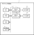
- FIG. 1 is a diagram showing an example of the hardware configuration of the program creation device.
- the program creation device 1 is, for example, a device that creates a coordinate conversion program that performs coordinate conversion of coordinate values instructed in a machining program.
- the program creation device 1 is mounted on, for example, a PC (Personal Computer) or a numerical control device that controls a machine tool.
- PC Personal Computer
- FIG. 1 an example in which the program creation device 1 is mounted on a PC will be described.
- the program creation device 1 includes a CPU (Central Processing Unit) 2, a bus 3, a ROM (Read Only Memory) 4, a RAM (Random Access Memory) 5, and a non-volatile memory 6.
- a CPU Central Processing Unit
- ROM Read Only Memory
- RAM Random Access Memory
- the CPU 2 is a processor that controls the entire program creation device 1 according to a system program.
- the CPU 2 reads a system program or the like stored in the ROM 4 via the bus 3.
- Bus 3 is a communication path that connects each hardware in the program creation device 1 to each other. Each piece of hardware in the program creation device 1 exchanges data via the bus 3.
- ROM 4 is a storage device that stores a system program or the like for controlling the entire program creation device 1.
- RAM 5 is a storage device that temporarily stores various data.
- the RAM 5 temporarily stores data for display, data input from the outside, and the like.
- the RAM 5 functions as a work area for the CPU 2 to process various data.
- the non-volatile memory 6 is a storage device that holds data even when the power of the program creation device 1 is turned off and the power is not supplied to the program creation device 1.
- the non-volatile memory 6 is composed of, for example, an SSD (Solid State Drive).
- the non-volatile memory 6 stores, for example, various information input from the coordinate conversion program created by the program creation device 1 and the input device 10.
- the program creation device 1 further includes a first interface 7 and a second interface 8.
- the first interface 7 is an interface for connecting the bus 3 and the display device 9.
- the first interface 7 sends, for example, various data processed by the CPU 2 to the display device 9.
- the display device 9 is a device that receives various data via the first interface 7 and displays various data.
- the display device 9 displays, for example, a coordinate conversion program stored in the non-volatile memory 6.
- the display device 9 is a display such as an LCD (Liquid Crystal Display).
- the second interface 8 is an interface for connecting the bus 3 and the input device 10.
- the second interface 8 sends, for example, the data input from the input device 10 to the CPU 2 via the bus 3.
- the input device 10 is a device for inputting various data.
- the input device 10 receives, for example, the input of the coordinate conversion information of each tool and sends it to the non-volatile memory 6 via the second interface 8.
- the coordinate conversion information will be described in detail later.
- the input device 10 is, for example, a keyboard and a mouse.
- the input device 10 and the display device 9 may be configured as one device such as a touch panel.
- FIG. 2 is a block diagram showing an example of the function of the program creation device 1.
- the program creation device 1 includes, for example, an information storage unit 11, an execution command generation unit 12, a program creation unit 13, and an output unit 14.
- the information storage unit 11 is realized by storing the data input from the input device 10 or the like or the calculation result of the calculation process by the CPU 2 in the RAM 5 or the non-volatile memory 6. Further, the execution command generation unit 12, the program creation unit 13, and the output unit 14 are realized by, for example, the CPU 2 performing arithmetic processing using the system program stored in the ROM 4 and various data. The CPU 2 uses the RAM 5 as a work area to execute arithmetic processing.
- the information storage unit 11 stores coordinate conversion information for converting a coordinate value in a rotating coordinate system into a coordinate value in a reference coordinate system.
- the coordinate system is a general term for the origin, coordinate axes, etc., which are the reference for expressing the position on the machine tool.
- the coordinate system is, for example, a three-axis Cartesian coordinate system including an X-axis, a Y-axis, and a Z-axis that are orthogonal to each other.
- the machine tool processes the work based on the coordinate values in the reference coordinate system that is the reference for controlling each axis.
- the reference coordinate system is set so that, for example, the Z axis and the main axis are parallel, and the X axis and the Y axis are parallel to each other in the moving direction of the table.
- the reference coordinate system is set so that, for example, the Z axis and the spindle are parallel, and the X axis and the Y axis are parallel to the moving direction of the tool post, respectively. Will be done.
- the rotating coordinate system is a coordinate system set according to the direction of the tool or the cutting direction of the tool, and is a coordinate system in which the reference coordinate system is rotated by a predetermined angle around a predetermined axis.
- the rotating coordinate system may be a coordinate system that is translated in a predetermined axial direction, if necessary.
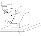
- FIG. 3 is a diagram illustrating the relationship between the reference coordinate system and the rotating coordinate system.
- the Z axis of the reference coordinate system Cc is parallel to the longitudinal direction of the main axis S, and the X axis and the Y axis are parallel to the moving direction of the table TB, respectively.
- the Z axis of the rotating coordinate system Cr is parallel to the longitudinal direction of the tool T.
- the rotating coordinate system Cr is a coordinate system obtained by rotating the reference coordinate system Cc around the X axis by an angle ⁇ .
- the origin of the reference coordinate system Cc and the origin of the rotating coordinate system Cr do not necessarily have to match.
- the origin of the rotating coordinate system Cr may be a point where the origin of the reference coordinate system Cc is translated by ⁇ X, ⁇ Y, and ⁇ Z in the X-axis, Y-axis, and Z-axis directions, respectively.
- the coordinate conversion information is information for converting the coordinate value in the rotating coordinate system Cr into the coordinate value in the reference coordinate system Cc.
- the coordinate conversion information is, for example, coordinate difference information indicating a difference between the reference coordinate system Cc and the rotating coordinate system Cr.
- the coordinate difference information includes information indicating the rotation center of the rotating coordinate system Cr and information indicating the rotation angle. However, the coordinate difference information does not include the translation amounts ⁇ X, ⁇ Y, and ⁇ Z from the origin of the reference coordinate system Cc to the origin of the rotating coordinate system Cr.
- the coordinate conversion information is set according to the mounting direction of the tool T with respect to the spindle S.
- the tool T is attached to the angle head AH for tilting the main axis S about the X axis by an angle ⁇ .
- the coordinate conversion information includes information indicating the X-axis, which is the rotation center of the rotating coordinate system Cr, and the angle ⁇ .
- the information storage unit 11 stores the coordinate conversion information in association with the unique identification information assigned to each tool T.
- the unique identification information assigned to the tool T is, for example, the tool number of each tool T.
- the information storage unit 11 may store information indicating the tool type in association with the identification information unique to each tool T.
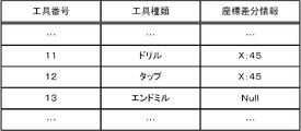
- FIG. 4 is a diagram showing an example of information stored by the information storage unit 11.
- the information storage unit 11 stores information indicating the tool type and coordinate conversion information in association with the tool number.
- the tool number 11 is stored in association with "drill” as the tool type and "X: 45" as the coordinate conversion information.
- “X: 45” indicates that the rotating coordinate system Cr is rotated by 45 ° around the X axis of the reference coordinate system Cc. In other words, it indicates that the tool T is mounted in a direction rotated by 45 ° around the X axis with respect to the longitudinal direction of the spindle S.
- the tool number 12 is stored in association with "tap” as the tool type and "X: 45" as the coordinate conversion information.
- the tool number 13 is stored in association with "end mill” as the tool type and "Null” as the coordinate conversion information. “Null” indicates that there is no difference between the rotating coordinate system Cr and the reference coordinate system Cc, and that the longitudinal direction of the tool T is mounted parallel to the longitudinal direction of the spindle S.
- the coordinate conversion information is input from the input device 10 by the user and stored in the information storage unit 11, for example.
- the execution command generation unit 12 generates an execution command "DO NOTHING" that does not convert the coordinate values that command the movement path of the end mill of the tool number 13.
- the program creation unit 13 creates a coordinate conversion program including an execution command for coordinate conversion generated by the execution command generation unit 12.
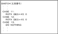
- FIG. 5 is a diagram showing an example of a coordinate conversion program created by the program creation unit 13.
- the coordinate conversion program shown in FIG. 5 is a coordinate conversion program generated when the information shown in FIG. 4 is stored in the information storage unit 11.
- the SWITCH statement defines an execution command to be executed corresponding to the identification information.
- an execution command for coordinate conversion that rotates the coordinate value by 45 ° around the X axis is specified.
- a coordinate conversion execution command for rotating the coordinate value by 45 ° around the X axis is specified.
- an execution command that does not perform coordinate conversion of coordinate values is specified.
- the output unit 14 outputs the coordinate conversion program generated by the program creation unit 13.
- the output unit 14 outputs, for example, a coordinate conversion program to the numerical control device 22 of the machine tool 21 connected to the program creation device 1 via the Internet line 20.
- the numerical control device 22 is a device that controls each axis of the machine tool 21 according to a machining program to perform machining of a workpiece.
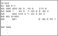
- FIG. 6 is a diagram showing an example of a machining program executed by the numerical control device 22.
- the command "M6 T11" on the first line is a tool change command to the tool T of the tool number 11.
- the commands "G90" and "G00 X0.0 Y0.0 Z10.0" on the second line are an absolute command and a positioning command for the tool T, respectively. These commands are commands for positioning the tool T at a position (0.0, 0.0, 10.0) in the reference coordinate system Cc.
- the commands "G68.1” and "X0.0 Y-20.0 Z-20.0" on the third line are the coordinate conversion command and the origin of the reference coordinate system Cc to the origin of the rotating coordinate system Cr, respectively. Shows the amount of translation of. This translation amount is specified by the coordinate value in the reference coordinate system Cc. Further, when only "G68.1” is instructed, it is considered that there is no translation amount. That is, the origin of the reference coordinate system Cc and the origin of the rotating coordinate system Cr coincide with each other.
- the coordinate conversion command is a command for converting the coordinate values until the coordinate conversion is canceled into the coordinate values in the reference coordinate system Cc. That is, the coordinate value written between the coordinate conversion command and the coordinate conversion cancel command is the coordinate value in the rotating coordinate system Cr, and is coordinate-converted to the coordinate value in the reference coordinate system Cc by the coordinate conversion execution command. The coordinates.
- the command "G00 X10.0 Y-20.0 Z5.0" on the fourth line is a positioning command.
- the coordinate value in this positioning command is the coordinate value in the rotating coordinate system Cr.
- the command "M3 S1000" on the 5th line is a spindle forward rotation command.
- the spindle forward rotation command is a command to rotate the spindle S forward at a rotation speed of 1,000 [rpm].
- the command "G01 Z-20.0 F0.1" on the sixth line is a linear interpolation command.
- This linear interpolation command is a command to move the tool T to the position of Z: -20.0 at a feed rate of 0.1 [mm / rev].
- the command "G69" on the 9th line is a coordinate conversion cancellation command. This command cancels the coordinate transformation.
- the numerical control device 22 acquires these machining command information from the machining program.
- the numerical control device 22 sets the coordinate values indicating the movement path of the tool T of the tool number 11. Coordinate conversion is performed based on the coordinate conversion program.
- the numerical control device 22 receives the coordinate values (10.0, -20.0, 5.0) in the positioning command of the tool T of the tool number 11. And the coordinate value (10.0, -20.0, -20.0) in the linear interpolation command is executed.
- the command "ROTX DEG 45.0” and the parallel movement amount "X0.0 Y” from the origin of the reference coordinate system Cc. -20.0 Coordinates are converted based on "Z-20.0". That is, the numerical control device 22 sets the coordinate values (10.0, -20.0, 5.0) and the coordinate values (10.0, -20.0, -20.0) at 45 ° around the X axis.
- the numerical control device 22 generates a coordinate conversion matrix for converting the coordinate values in the rotating coordinate system Cr into the coordinate values in the reference coordinate system Cc, for example, based on the execution command included in the coordinate conversion program.
- the numerical control device 22 processes the coordinate conversion matrix R x ( ⁇ ) shown by the following equation (1). Multiplies the coordinate values specified by the program. As a result, the coordinate values in the rotating coordinate system Cr acquired from the machining program can be converted into the coordinate values in the reference coordinate system Cc.
- the numerical control device 22 controls each axis based on the coordinate values in the reference coordinate system Cc.
- the numerical control device 22 controls the movement of the tool T based on the coordinate-converted coordinate values.
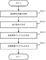
- FIG. 7 is a flowchart showing a process executed by the program creation device 1 when the coordinate conversion program is created.
- the execution command generation unit 12 acquires the coordinate conversion information stored in the information storage unit 11 (step SA01).
- the execution command generation unit 12 generates an execution command for coordinate conversion for each identification information based on the acquired coordinate conversion information (step SA02).
- the program creation unit 13 creates a coordinate conversion program based on the coordinate conversion execution command for each identification information generated by the execution command generation unit 12 (step SA03).
- the output unit 14 outputs the coordinate conversion program created by the program creation unit 13. (Step SA04).
- the program creation device 1 of the first embodiment associates the coordinate conversion information for converting the coordinate values in the rotating coordinate system into the coordinate values in the reference coordinate system with the identification information assigned to the tool.
- the information storage unit 11 that stores the coordinates
- the execution command generation unit 12 that generates the execution command of the coordinate conversion based on the coordinate conversion information stored in the information storage unit 11, and the execution command generated by the execution command generation unit 12.
- a program creation unit 13 for creating a coordinate conversion program including the above is provided.
- the coordinate conversion information includes the coordinate difference information indicating the difference between the rotating coordinate system and the reference coordinate system, and the execution command generation unit 12 is based on the coordinate difference information. Generate an execution command. Therefore, the information stored in the information storage unit 11 can be simplified.
- the program creation device 1 includes, for example, an information storage unit 11, an execution command generation unit 12, a program creation unit 13, and an output unit 14.
- the information storage unit 11 stores the coordinate conversion information for converting the coordinate value in the rotating coordinate system Cr into the coordinate value in the reference coordinate system Cc.
- the coordinate conversion information includes reference direction information and cutting direction information.
- the reference direction information is information indicating the reference machining direction determined according to the tool type.
- the reference machining direction is the ⁇ X direction in the reference coordinate system Cc.
- the cutting direction information is information indicating the cutting direction of the tool T.
- the cutting direction of the turning tool is the ⁇ X direction.
- the reference machining direction and the cutting direction of the tool T coincide with each other.
- the cutting direction of the turning tool is the -Y direction.
- the cutting direction of the tool is the direction in which the reference machining direction is rotated by 90 ° around the Z axis.
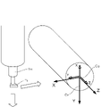
- FIG. 8 is a diagram illustrating a reference processing direction and cutting direction.
- a turning tool Tt is attached to the tool holder TH.
- the reference processing direction is the ⁇ X direction in the reference coordinate system Cc.
- the turning tool Tt is attached substantially parallel to the YZ plane in the reference coordinate system Cc, and the turning tool Tt cuts in the ⁇ Y direction when the workpiece is machined. Therefore, the cutting direction of the turning tool Tt is the direction in which the reference machining direction is rotated by 90 ° around the Z axis.
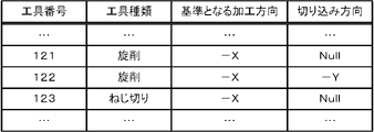
- FIG. 9 is a diagram showing an example of information stored by the information storage unit 11.
- the information storage unit 11 stores information indicating the tool type, reference direction information, and cutting direction information in association with the tool number.
- the tool number 121 stores "turning" as the tool type, "-X” as the reference direction information, and "Null” as the cutting direction information.
- the cutting direction of the tool T is the same ⁇ X direction as the reference machining direction.
- the tool number 122 stores "turning" as the tool type, "-X” as the reference direction information, and "-Y” as the cutting direction information.
- the tool T is attached substantially parallel to the YY plane in the reference coordinate system Cc, and the cut is made in the ⁇ Y direction.
- the tool number 123 stores "thread cutting” as the tool type, "-X” as the reference direction information, and "Null” as the cutting direction information. In this case, the cutting direction of the thread cutting tool coincides with the reference machining direction.
- the execution command generation unit 12 (see FIG. 2) generates an execution command for coordinate conversion based on the difference between the direction indicated by the reference direction information stored in the information storage unit 11 and the direction indicated by the cutting direction information.
- the execution command generation unit 12 stores the reference direction information “ ⁇ X” and the cutting direction information “ ⁇ Y” associated with the tool number 122. Generate a command to execute coordinate transformation based on this.
- the difference between the cutting direction of the turning tool Tt of the tool number 122 and the reference machining direction is 90 ° around the Z axis.
- the rotating coordinate system Cr is a coordinate system in which the reference coordinate system Cc is rotated by 90 ° around the Z axis.
- the execution command generation unit 12 generates a coordinate conversion execution command for converting the coordinate values in the rotating coordinate system Cr rotated 90 ° around the Z axis with respect to the reference coordinate system Cc into the coordinate values in the reference coordinate system Cc. do.
- the execution command generation unit 12 has the turning tool Tt of the tool number 121 and the thread cutting tool of the tool number 123. Generates an execution command "DO NOTHING" that does not perform coordinate conversion of the coordinate values that command the movement path of.
- the program creation unit 13 generates a program including an execution command for coordinate conversion generated for each identification information by the execution command generation unit 12.
- the output unit 14 outputs the coordinate conversion program generated by the program creation unit 13.
- the output unit 14 outputs the coordinate conversion program to, for example, the numerical control device 22 connected to the program creation device 1 via the Internet line.
- the coordinate conversion information includes the reference direction information indicating the machining direction which is the reference of the tool T set for each identification information and the cutting direction of the tool T.
- the execution command generation unit 12 generates an execution command based on the difference between the direction indicated by the reference direction information and the direction indicated by the cut direction information.
- the program creation device 1 includes, for example, an information storage unit 11, an execution command generation unit 12, a program creation unit 13, and an output unit 14.
- the information storage unit 11 stores the coordinate conversion information for converting the coordinate value in the rotating coordinate system Cr into the coordinate value in the reference coordinate system Cc.
- the coordinate conversion information includes coordinate difference information indicating the difference between the reference coordinate system Cc and the rotating coordinate system Cr.
- the coordinate difference information includes, for example, information indicating the rotation center of the rotating coordinate system Cr and information indicating the rotation angle. Further, the coordinate difference information can be determined by associating the information indicating the rotation center of the rotating coordinate system Cr and the information indicating the rotation angle with the position information indicating the position at the start of cutting of the tool T.
- the coordinate difference information is Z: 90.
- the position information is Y> 0.0, for example, as shown in FIG. 10, the turning tool Tt is positioned on the + Y side of the reference coordinate system Cc in the YZ plane at the start of cutting. In this case, the cutting direction of the tool T is the ⁇ Y direction.
- the position information indicating the position of the turning tool is Y ⁇ 0.0
- the coordinate difference information is Z: 270.
- the position information is Y ⁇ 0.0, for example, as shown in FIG. 11, the turning tool Tt is positioned on the ⁇ Y side of the YZ plane of the reference coordinate system Cc at the start of cutting. In this case, the cutting direction of the tool T is the + Y direction.
- FIG. 12 is a diagram showing an example of information stored by the information storage unit 11.
- the information storage unit 11 stores information indicating the tool type and coordinate difference information in association with the tool number.
- the tool number 131 is stored in association with "turning" as the tool type and "Null" as the coordinate difference information. In this case, the coordinate conversion of the coordinate value that commands the movement path of the tool T of the tool number 131 is not performed.
- the tool number 133 is stored in association with "thread cutting" as the tool type and "Null” as the tool conversion information.
- the execution command generation unit 12 (see FIG. 2) generates an execution command for coordinate conversion for each identification information based on the coordinate conversion information stored in the information storage unit 11. For example, when the information shown in FIG. 12 is stored in the information storage unit 11, the execution command generation unit 12 does not convert the coordinate values that command the movement path of the turning tool of the tool number 131, and the execution command "DO NOTHING". To generate.
- execution command generation unit 12 generates an execution command "DO NOTHING" that does not perform coordinate conversion of the coordinate values that command the movement path of thread cutting of the tool number 133.
- the program creation unit 13 generates a program including an execution command for coordinate conversion generated for each identification information by the execution command generation unit 12.
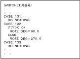
- FIG. 13 is a diagram showing an example of a coordinate conversion program generated by the program creation unit 13.
- the coordinate conversion program shown in FIG. 13 is a coordinate conversion program generated when the information shown in FIG. 12 is stored in the information storage unit 11.
- the SWITCH statement defines an execution command to be executed corresponding to the identification information.
- the coordinate value is rotated by 90 ° around the Z axis, and the tool is ⁇ Y in the reference coordinate system Cc.
- the coordinate values be rotated by -270 ° around the Z axis.
- the output unit 14 outputs the coordinate conversion program generated by the program creation unit 13.
- the output unit 14 outputs the coordinate conversion program to, for example, the numerical control device 22 connected to the program creation device 1 via the Internet line.
- the numerical control device 22 sets the coordinate values indicating the movement path of the tool T of the tool number 132. Coordinate conversion is performed based on the coordinate conversion program.
- the numerical control device 22 performs coordinate conversion of the coordinate values in the positioning command and the linear interpolation command based on the position information indicating the position of the tool T.
- the numerical control device 22 rotates the coordinate values indicating the movement path of the tool of the tool number 132 by 90 ° around the Z axis, so that these coordinate values are changed from the coordinate values in the rotating coordinate system Cr to the reference coordinate system Cc. Convert coordinates to coordinate values.
- the coordinate conversion information includes the coordinate difference information indicating the difference between the rotating coordinate system and the reference coordinate system, and the coordinate difference information includes the position of the tool.
- the program creation device 1 may be mounted on the numerical control device 22 of the machine tool 21.
- each configuration in the above-mentioned first to third embodiments may be combined as appropriate.
- Program creation device 2 CPU 3 bus 4 ROM 5 RAM 6 Non-volatile memory 7 1st interface 8 2nd interface 9 Display device 10 Input device 11 Information storage unit 12 Execution command generation unit 13 Program creation unit 14 Output unit 20 Internet line 21 Machine tool 22 Numerical control device AH Angle head Cc Reference Coordinate System Cr Rotation Coordinate System S Spindle Axis TB Table T Tool Tt Turning Tool TH Tool Holder
Landscapes
- Engineering & Computer Science (AREA)
- Human Computer Interaction (AREA)
- Manufacturing & Machinery (AREA)
- Physics & Mathematics (AREA)
- General Physics & Mathematics (AREA)
- Automation & Control Theory (AREA)
- Numerical Control (AREA)
Abstract
プログラム作成装置が、回転座標系における座標値を基準座標系における座標値に座標変換するための座標変換情報を工具に割り当てられた識別情報に関連付けて記憶する情報記憶部と、識別情報に関連付けて記憶された座標変換情報に基づいて、座標変換の実行指令を生成する実行指令生成部と、実行指令生成部によって生成された座標変換の実行指令を含む座標変換プログラムを作成するプログラム作成部と、を備える。
Description
本開示は、プログラム作成装置、および工作機械に関する。
従来、座標変換機能を有する数値制御装置において加工プログラムを作成することが行われている。座標変換機能を有する数値制御装置では、例えば、基準となる座標系を所定の軸回りに所定角度だけ回転させた座標系における座標値を用いて工具の移動経路を指令する加工プログラムが作成される。この場合、移動経路を指令する座標値は、基準となる座標系における座標値に座標変換され、座標変換された座標値に基づいて工具の移動が制御される。
しかし、従来の数値制御装置において座標変換を指令する加工プログラムを作成する場合、座標系の回転中心、回転方向、および回転量などの情報を加工プログラムに書き込む必要がある。そのため、加工プログラムが複雑化し、加工プログラムの可読性が低下するおそれがある。また、加工プログラムの可読性が低下すると、ワークの加工ミスにつながるおそれがある。
本開示は、加工プログラムの可読性を高め、加工ミスを低減することが可能なプログラム作成装置、および工作機械を提供することを目的とする。
プログラム作成装置が、回転座標系における座標値を基準座標系における座標値に座標変換するための座標変換情報を工具に割り当てられた識別情報に関連付けて記憶する情報記憶部と、情報記憶部に記憶された座標変換情報に基づいて、座標変換の実行指令を生成する実行指令生成部と、実行指令生成部によって生成された実行指令を含む座標変換プログラムを作成するプログラム作成部と、を備える。
本開示により、加工プログラムの可読性を高め、加工ミスを低減することが可能となる。
[第1の実施形態]
以下、第1の実施形態について図面を用いて説明する。
以下、第1の実施形態について図面を用いて説明する。
図1は、プログラム作成装置のハードウェア構成の一例を示す図である。プログラム作成装置1は、例えば、加工プログラムにおいて指令される座標値の座標変換を行う座標変換プログラムを作成する装置である。プログラム作成装置1は、例えば、PC(Personal Compuuter)、工作機械を制御する数値制御装置に実装される。ここでは、プログラム作成装置1がPCに実装された例について説明する。
プログラム作成装置1は、CPU(Central Processing Unit)2と、バス3と、ROM(Read Only Memory)4と、RAM(Random Access Memory)5と、不揮発性メモリ6とを備えている。
CPU2は、システムプログラムに従ってプログラム作成装置1の全体を制御するプロセッサである。CPU2は、バス3を介してROM4に格納されたシステムプログラムなどを読み出す。
バス3は、プログラム作成装置1内の各ハードウェアを互いに接続する通信路である。プログラム作成装置1内の各ハードウェアはバス3を介してデータをやり取りする。
ROM4は、プログラム作成装置1全体を制御するためのシステムプログラムなどを記憶する記憶装置である。
RAM5は、各種データを一時的に格納する記憶装置である。RAM5は、表示用のデータ、外部から入力されるデータなどを一時的に記憶する。RAM5は、CPU2が各種データを処理するための作業領域として機能する。
不揮発性メモリ6は、プログラム作成装置1の電源が切られ、プログラム作成装置1に電源が供給されていない状態でもデータを保持する記憶装置である。不揮発性メモリ6は、例えば、SSD(Solid State Drive)で構成される。不揮発性メモリ6は、例えば、プログラム作成装置1が作成した座標変換プログラム、入力装置10から入力された各種情報を記憶する。
プログラム作成装置1は、さらに、第1のインタフェース7と、第2のインタフェース8とを備えている。
第1のインタフェース7は、バス3と表示装置9とを接続するインタフェースである。第1のインタフェース7は、例えば、CPU2が処理した各種データを表示装置9に送る。
表示装置9は、第1のインタフェース7を介して各種データを受け、各種データを表示する装置である。表示装置9は、例えば、不揮発性メモリ6に記憶された座標変換プログラムなどを表示する。表示装置9は、LCD(Liquid Crystal Display)などのディスプレイである。
第2のインタフェース8は、バス3と入力装置10とを接続するインタフェースである。第2のインタフェース8は、例えば、入力装置10から入力されたデータをバス3を介してCPU2に送る。
入力装置10は、各種データを入力するための装置である。入力装置10は、例えば、各工具の座標変換情報の入力を受け、第2のインタフェース8を介して不揮発性メモリ6に送る。座標変換情報については後に詳しく説明する。入力装置10は、例えば、キーボード、およびマウスである。なお、入力装置10と表示装置9とは、例えば、タッチパネルのように1つの装置として構成されてもよい。
次に、プログラム作成装置1の各部の機能について説明する。
図2は、プログラム作成装置1の機能の一例を示すブロック図である。プログラム作成装置1は、例えば、情報記憶部11と、実行指令生成部12と、プログラム作成部13と、出力部14とを備えている。
情報記憶部11は、入力装置10などから入力されたデータ、またはCPU2による演算処理の演算結果がRAM5、または不揮発性メモリ6に記憶されることにより実現される。また、実行指令生成部12、プログラム作成部13、および出力部14は、例えば、CPU2がROM4に記憶されているシステムプログラム、および各種データを用いて演算処理することにより実現される。CPU2は、作業領域としてRAM5を用いて演算処理を実行する。
情報記憶部11は、回転座標系における座標値を基準座標系における座標値に変換するための座標変換情報を記憶する。
座標系とは工作機械上における位置を表すための基準となる原点、座標軸などの総称である。座標系は、例えば、互いに直交するX軸、Y軸およびZ軸からなる3軸直交座標系である。
ここで、工作機械について説明する。工作機械は、各軸の制御の基準となる基準座標系における座標値に基づいてワークの加工を行う。工作機械がマシニングセンタである場合、基準座標系は、例えば、Z軸と主軸とが平行であり、かつ、X軸とY軸とがそれぞれ、テーブルの移動方向に平行になるように設定される。また、工作機械が旋盤である場合、基準座標系は、例えば、Z軸と主軸とが平行であり、かつ、X軸とY軸とがそれぞれ、刃物台の移動方向に平行になるように設定される。
回転座標系とは、工具の向き、または工具の切り込み方向に合わせて設定される座標系であり、基準座標系を所定の軸回りに所定の角度回転させた座標系である。回転座標系は、さらに、必要に応じて所定の軸方向に平行移動させた座標系であってもよい。
図3は、基準座標系と回転座標系との関係を説明する図である。基準座標系CcのZ軸は主軸Sの長手方向に平行であり、X軸およびY軸は、テーブルTBの移動方向にそれぞれ平行である。回転座標系CrのZ軸は、工具Tの長手方向に平行である。回転座標系Crは、基準座標系CcをX軸回りに角度θだけ回転させた座標系である。基準座標系Ccの原点と回転座標系Crの原点は必ずしも一致している必要はない。回転座標系Crの原点は、基準座標系Ccの原点をX軸、Y軸、Z軸方向にそれぞれΔX、ΔY、ΔZだけ平行移動した点であってもよい。
座標変換情報は、回転座標系Crにおける座標値を基準座標系Ccにおける座標値に変換するための情報である。座標変換情報は、例えば、基準座標系Ccと回転座標系Crとの差分を示す座標差分情報である。座標差分情報は、回転座標系Crの回転中心を示す情報、および回転角度を示す情報を含む。ただし、座標差分情報には基準座標系Ccの原点から回転座標系Crの原点への平行移動量ΔX、ΔY、ΔZは含まれない。
座標変換情報は、主軸Sに対する工具Tの取り付け方向に応じて設定される。図3に示す例では、工具Tは、主軸Sに対してX軸周りに角度θだけ傾けるためのアングルヘッドAHに取り付けられている。この場合、座標変換情報は、回転座標系Crの回転中心であるX軸、および角度θを示す情報を含む。
また、情報記憶部11は、座標変換情報を各工具Tに割り当てられた固有の識別情報に関連付けて記憶する。工具Tに割り当てられた固有の識別情報とは、例えば、各工具Tの工具番号である。情報記憶部11は、各工具Tに固有の識別情報に関連付けて工具種類を示す情報を記憶してもよい。
図4は、情報記憶部11が記憶する情報の一例を示す図である。情報記憶部11は、工具番号に関連付けて、工具種類を示す情報および座標変換情報を記憶する。
具体的に、工具番号11には、工具種類として「ドリル」、座標変換情報として「X:45」が関連付けて記憶されている。「X:45」は、回転座標系Crが基準座標系CcのX軸回りに45°回転したものであることを示す。換言すれば、工具Tが主軸Sの長手方向に対してX軸回りに45°回転した向きに取り付けられていることを示す。
工具番号12には、工具種類として「タップ」、座標変換情報として「X:45」が関連付けて記憶されている。
工具番号13には、工具種類として「エンドミル」、座標変換情報として「Null」が関連付けて記憶されている。「Null」は、回転座標系Crと基準座標系Ccとの間に差がなく、工具Tの長手方向が主軸Sの長手方向と平行に取り付けられていることを示す。
座標変換情報は、例えば、ユーザにより、入力装置10から入力されて情報記憶部11に記憶される。
ここで、図2の説明に戻る。
実行指令生成部12は、情報記憶部11に記憶された座標変換情報に基づいて、識別情報ごとの座標変換の実行指令を生成する。例えば、情報記憶部11に図4に示す情報が記憶されている場合、実行指令生成部12は、工具番号11のドリルの移動経路を指令する座標値を、X軸回りに45°回転させる座標変換の実行指令「ROTX DEG=45.0」を生成する。言い換えれば、実行指令生成部12は、基準座標系Ccに対してX軸周りに45°回転した回転座標系Crにおける座標値を基準座標系Ccにおける座標値に変換する座標変換の実行指令を生成する。
また、実行指令生成部12は、工具番号12のタップの移動経路を指令する座標値を、X軸回りに45°回転させる座標変換の実行指令「ROTX DEG=45.0」を生成する。
一方、工具番号13には、座標変換情報「Null」が関連付けて記憶されている。そのため、実行指令生成部12は、工具番号13のエンドミルの移動経路を指令する座標値を、座標変換しない実行指令「DO NOTHING」を生成する。
ここで、図2の説明に戻る。
プログラム作成部13は、実行指令生成部12によって生成された座標変換の実行指令を含む座標変換プログラムを作成する。
図5は、プログラム作成部13によって作成される座標変換プログラムの一例を示す図である。図5に示す座標変換プログラムは、図4に示す情報が情報記憶部11に記憶されている場合に生成される座標変換プログラムである。
この座標変換プログラムでは、SWITCH文によって、識別情報に対応して実行される実行指令が規定されている。
具体的に、工具番号11の工具に対しては、座標値をX軸回りに45°回転させる座標変換の実行指令が規定されている。工具番号12の工具に対しては、座標値をX軸回りに45°回転させる座標変換の実行指令が規定されている。工具番号13の工具に対しては、座標値の座標変換を行わない実行指令が規定されている。
出力部14は、プログラム作成部13によって生成された座標変換プログラムを出力する。出力部14は、例えば、プログラム作成装置1にインターネット回線20を介して接続された工作機械21の数値制御装置22に座標変換プログラムを出力する。
ここで、数値制御装置22について説明する。数値制御装置22は、加工プログラムに従って工作機械21の各軸を制御し、ワークの切削加工を行う装置である。
図6は、数値制御装置22において実行される加工プログラムの一例を示す図である。
第1行目の指令「M6 T11」は、工具番号11の工具Tへの工具交換指令である。
第2行目の指令「G90」、および「G00 X0.0 Y0.0 Z10.0」はそれぞれ、アブソリュート指令、および工具Tの位置決め指令である。これらの指令は、基準座標系Ccにおける位置(0.0,0.0,10.0)に工具Tを位置決めする指令である。
第3行目の指令「G68.1」、および「X0.0 Y-20.0 Z-20.0」はそれぞれ、座標変換指令、および基準座標系Ccの原点から回転座標系Crの原点への平行移動量を示している。この平行移動量は基準座標系Ccでの座標値で指定される。また、「G68.1」のみを指令した場合、平行移動量はないものとみなされる。すなわち、基準座標系Ccの原点と回転座標系Crの原点は一致する。座標変換指令は、座標変換がキャンセルされるまでの座標値を、基準座標系Ccにおける座標値に座標変換する指令である。つまり、座標変換指令と座標変換のキャンセル指令との間に書かれている座標値は、回転座標系Crにおける座標値であり、座標変換の実行指令によって基準座標系Ccにおける座標値に座標変換される。
第4行目の指令「G00 X10.0 Y-20.0 Z5.0」は、位置決め指令である。この位置決め指令における座標値は、回転座標系Crにおける座標値である。
第5行目の指令「M3 S1000」は主軸正転指令である。主軸正転指令は、主軸Sを回転数1,000[rpm]で正転させる指令である。
第6行目の指令「G01 Z-20.0 F0.1」は、直線補間指令である。この直線補間指令は、Z:-20.0の位置まで0.1[mm/rev]の送り速度で工具Tを移動させる指令である。
第9行目の指令「G69」は座標変換キャンセル指令である。この指令により座標変換がキャンセルされる。
数値制御装置22は、加工プログラムからこれらの加工指令情報を取得する。
次に、数値制御装置22がプログラム作成装置1からの座標変換プログラムを読み込み、さらに、加工プログラムが実行されたときの処理について説明する。
例えば、数値制御装置22において図5に示す座標変換プログラムが読み込まれ、図6に示す加工プログラムが実行された場合、数値制御装置22は、工具番号11の工具Tの移動経路を示す座標値を座標変換プログラムに基づいて座標変換する。
具体的に、数値制御装置22は、座標変換指令「G68.1」が読み込まれると、工具番号11の工具Tの位置決め指令における座標値(10.0,-20.0,5.0)、および直線補間指令における座標値(10.0,-20.0,-20.0)を実行指令「ROTX DEG=45.0」および基準座標系Ccの原点からの平行移動量「X0.0 Y-20.0 Z-20.0」に基づいて座標変換する。すなわち、数値制御装置22は、座標値(10.0,-20.0,5.0)、および座標値(10.0,-20.0,-20.0)をX軸回りに45°回転させ、かつ、X軸、Y軸、Z軸方向にそれぞれ0.0、-20.0、-20.0だけ平行移動させることによって、これらの座標値を回転座標系Crにおける座標値から基準座標系Ccにおける座標値に座標変換する。
数値制御装置22は、例えば、座標変換プログラムに含まれる実行指令に基づいて、回転座標系Crにおける座標値を基準座標系Ccにおける座標値に座標変換するための座標変換行列を生成する。回転座標系Crが基準座標系Ccに対してX軸回りに角度θだけ回転した座標系である場合、数値制御装置22は、以下の数1式で示す座標変換行列Rx(θ)を加工プログラムで規定された座標値に乗算する。これにより、加工プログラムから取得された回転座標系Crにおける座標値を基準座標系Ccにおける座標値に変換することができる。

数値制御装置22は、基準座標系Ccにおける座標値に基づいて各軸の制御を行う。加工プログラムにおいて座標変換指令が規定されている場合、数値制御装置22は、座標変換された座標値に基づいて工具Tの移動を制御する。
次に、座標変換プログラムが作成される際にプログラム作成装置1において実行される処理について説明する。
図7は、座標変換プログラムが作成される際にプログラム作成装置1において実行される処理を示すフローチャートである。
まず、実行指令生成部12は、情報記憶部11に記憶された座標変換情報を取得する(ステップSA01)。
次に、実行指令生成部12は、取得した座標変換情報に基づいて識別情報ごとの座標変換の実行指令を生成する(ステップSA02)。
次に、プログラム作成部13は、実行指令生成部12によって生成された識別情報ごとの座標変換の実行指令に基づいて座標変換プログラムを作成する(ステップSA03)。
最後に、出力部14は、プログラム作成部13によって作成された座標変換プログラムを出力する。(ステップSA04)。
以上説明したように、第1の実施形態のプログラム作成装置1は、回転座標系における座標値を基準座標系における座標値に座標変換するための座標変換情報を工具に割り当てられた識別情報に関連付けて記憶する情報記憶部11と、情報記憶部11に記憶された座標変換情報に基づいて、座標変換の実行指令を生成する実行指令生成部12と、実行指令生成部12によって生成された実行指令を含む座標変換プログラムを作成するプログラム作成部13と、を備える。
したがって、加工プログラムに座標変換のための座標系の回転中心、回転方向、および回転量などの情報を書き込む必要がない。その結果、加工プログラムの可読性を高め、加工ミスを低減することができる。
また、第1の実施形態のプログラム作成装置1では、座標変換情報は、回転座標系と基準座標系との差分を示す座標差分情報を含み、実行指令生成部12は、座標差分情報に基づいて実行指令を生成する。そのため、情報記憶部11に記憶させる情報を簡略化することができる。
[第2の実施形態]
次に、第2の実施形態について図面を用いて説明する。なお、第1の実施形態と同じ構成については、説明を省略する。
次に、第2の実施形態について図面を用いて説明する。なお、第1の実施形態と同じ構成については、説明を省略する。
プログラム作成装置1は、図2に示すとおり、例えば、情報記憶部11と、実行指令生成部12と、プログラム作成部13と、出力部14とを備えている。
情報記憶部11は、回転座標系Crにおける座標値を基準座標系Ccにおける座標値に変換するための座標変換情報を記憶する。座標変換情報は、基準方向情報と、切込方向情報とを含む。
基準方向情報は、工具種類に応じて定められた基準となる加工方向を示す情報である。例えば、工具Tがバイトなどの旋削工具である場合、基準となる加工方向は、基準座標系Ccにおける-X方向である。
切込方向情報は、工具Tの切り込み方向を示す情報である。例えば、旋削工具が基準座標系CcにおけるX-Z平面に略平行に取り付けられ、-X方向に向けて切り込みが行われる場合、旋削工具の切り込み方向は-X方向である。この場合、基準となる加工方向と工具Tの切り込み方向とは一致する。
一方、旋削工具が基準座標系CcにおけるY-Z平面に略平行に取り付けられ、-Y方向に向けて切り込みが行われる場合、旋削工具の切り込み方向は-Y方向である。この場合、工具の切り込み方向は、基準となる加工方向をZ軸回りに90°回転させた方向となる。
図8は、基準となる加工方向と切り込み方向を説明する図である。図8において、工具ホルダTHには旋削工具Ttが取り付けられている。この場合、基準となる加工方向は、基準座標系Ccにおける-X方向である。また、旋削工具Ttは基準座標系CcにおけるY-Z平面に対して略平行に取り付けられており、ワークの加工時に旋削工具Ttは-Y方向に向けて切り込む。したがって、旋削工具Ttの切り込み方向は、基準となる加工方向をZ軸回りに90°回転させた向きとなる。
図9は、情報記憶部11が記憶する情報の一例を示す図である。情報記憶部11には、工具番号に関連付けて、工具種類を示す情報、基準方向情報、および切込方向情報が記憶されている。
具体的に、工具番号121には、工具種類として「旋削」、基準方向情報として「-X」、切込方向情報として「Null」が関連付けて記憶されている。この場合、工具Tの切込方向は、基準となる加工方向と同じ-X方向である。
工具番号122には、工具種類として「旋削」、基準方向情報として「-X」、切込方向情報として「-Y」が関連付けて記憶されている。この場合、工具Tは、基準座標系CcにおけるY-Z平面に略平行に取り付けられ、かつ、-Y方向に向けて切り込みが行われる。
工具番号123には、工具種類として「ねじ切り」、基準方向情報として「-X」、切込方向情報として「Null」が関連付けて記憶されている。この場合、ねじ切り工具の切り込み方向は、基準となる加工方向に一致する。
実行指令生成部12(図2参照)は、情報記憶部11に記憶された基準方向情報が示す方向と、切込方向情報が示す方向との差に基づいて座標変換の実行指令を生成する。
例えば、情報記憶部11に図9に示す情報が記憶されている場合、実行指令生成部12は、工具番号122に関連付けられた基準方向情報「-X」および切込方向情報「-Y」に基づいて座標変換の実行指令を生成する。ここで、工具番号122の旋削工具Ttの切り込み方向と、基準となる加工方向との差は、Z軸回りにおいて90°である。この場合、回転座標系Crは基準座標系CcをZ軸回りに90°回転させた座標系である。したがって、実行指令生成部12は、工具番号122の旋削工具Ttの移動経路を指令する座標値を、Z軸回りに90°回転させる座標変換の実行指令「ROTZ DEG=90.0」を生成する。言い換えれば、実行指令生成部12は、基準座標系Ccに対してZ軸周りに90°回転した回転座標系Crにおける座標値を基準座標系Ccにおける座標値に変換する座標変換の実行指令を生成する。
また、工具番号121の旋削工具Ttおよび工具番号123のねじ切り工具の切込方向情報は「Null」であるため、実行指令生成部12は、工具番号121の旋削工具Ttおよび工具番号123のねじ切り工具の移動経路を指令する座標値を座標変換しない実行指令「DO NOTHING」を生成する。
プログラム作成部13は、実行指令生成部12によって識別情報ごとに生成された座標変換の実行指令を含むプログラムを生成する。
出力部14は、プログラム作成部13によって生成された座標変換プログラムを出力する。出力部14は、例えば、プログラム作成装置1にインターネット回線を介して接続された数値制御装置22に座標変換プログラムを出力する。
以上説明したように、第2の実施形態のプログラム作成装置1では、座標変換情報は、識別情報ごとに設定される工具Tの基準となる加工方向を示す基準方向情報と、工具Tの切り込み方向を示す切込方向情報とを含み、実行指令生成部12は、基準方向情報が示す方向と、切込方向情報が示す方向との差に基づいて実行指令を生成する。
したがって、加工プログラムに座標変換のための座標系の回転中心、回転方向、および回転量などの情報を書き込む必要がない。その結果、加工プログラムの可読性を高め、加工ミスを低減することができる。
[第3の実施形態]
次に、第3の実施形態について図面を用いて説明する。なお、第1の実施形態と同じ構成については、説明を省略する。
次に、第3の実施形態について図面を用いて説明する。なお、第1の実施形態と同じ構成については、説明を省略する。
プログラム作成装置1は、図2に示すとおり、例えば、情報記憶部11と、実行指令生成部12と、プログラム作成部13と、出力部14とを備えている。
情報記憶部11は、回転座標系Crにおける座標値を基準座標系Ccにおける座標値に変換するための座標変換情報を記憶する。座標変換情報は、基準座標系Ccと回転座標系Crとの差分を示す座標差分情報を含む。
座標差分情報は、例えば、回転座標系Crの回転中心を示す情報、および回転角度を示す情報を含む。また、座標差分情報は、回転座標系Crの回転中心を示す情報、および回転角度を示す情報を工具Tの切削開始時の位置を示す位置情報に対応させて定めることができる。
例えば、旋削工具の位置を示す位置情報がY>0.0である場合、座標差分情報はZ:90である。位置情報がY>0.0である場合とは、例えば図10に示すように、旋削工具Ttが切削開始時に基準座標系CcのY-Z平面における+Y側に位置決めされた場合である。この場合、工具Tの切り込み方向は-Y方向となる。
一方、旋削工具の位置を示す位置情報がY<0.0である場合、座標差分情報はZ:270である。位置情報がY<0.0である場合とは、例えば図11に示すように、旋削工具Ttが切削開始時に基準座標系CcのY-Z平面における-Y側に位置決めされた場合である。この場合、工具Tの切り込み方向は+Y方向となる。
図12は、情報記憶部11が記憶する情報の一例を示す図である。情報記憶部11には、工具番号に関連付けて、工具種類を示す情報、および座標差分情報が記憶される。
具体的には、工具番号131には、工具種類として「旋削」、座標差分情報として「Null」が関連付けて記憶されている。この場合、工具番号131の工具Tの移動経路を指令する座標値の座標変換は行われない。
工具番号132には、工具種類として「旋削」、工具差分情報として「IF Y> 0.0」、「THEN Z:90」、「ELSE Z:270」が関連付けて記憶されている。つまり、工具Tの位置情報がY>0.0である場合は、基準座標系Ccに対してZ軸回りに90°した回転座標系Crが設定される。また、工具の位置情報がY<0.0である場合は、基準座標系Ccに対してZ軸回りに270°した回転座標系Crが設定される。
工具番号133には、工具種類として「ねじ切り」、工具変換情報として「Null」が関連付けて記憶されている。
実行指令生成部12(図2参照)は、情報記憶部11に記憶された座標変換情報に基づいて、識別情報ごとの座標変換の実行指令を生成する。例えば、情報記憶部11に図12に示す情報が記憶されている場合、実行指令生成部12は、工具番号131の旋削工具の移動経路を指令する座標値を座標変換しない実行指令「DO NOTHING」を生成する。
また、実行指令生成部12は、工具番号132の旋削の移動経路を指令する座標値を、工具が位置決めされる位置に応じて、Z軸回りに90°回転させる実行指令「ROTZ DEG=90.0」またはZ軸回りに270°回転させる実行指令「ROTZ DEG=270.0」を生成する。
また、実行指令生成部12は、工具番号133のねじ切りの移動経路を指令する座標値を座標変換しない実行指令「DO NOTHING」を生成する。
プログラム作成部13は、実行指令生成部12によって識別情報ごとに生成された座標変換の実行指令を含むプログラムを生成する。
図13は、プログラム作成部13によって生成される座標変換プログラムの一例を示す図である。図13に示す座標変換プログラムは、図12に示す情報が情報記憶部11に記憶されている場合に生成される座標変換プログラムである。この座標変換プログラムでは、SWITCH文によって、識別情報に対応して実行される実行指令が規定されている。
具体的に、工具番号131の工具の移動経路を指令する座標値に対しては座標変換を行わないことが規定されている。
また、工具番号132の工具に対しては、工具Tが基準座標系Ccにおける+Y側に位置決めされる場合は、座標値をZ軸回りに90°回転させ、工具が基準座標系Ccにおける-Y側に位置決めされる場合は、座標値をZ軸回りに-270°回転させることが規定されている。
また、工具番号132の工具の移動経路を指令する座標値に対しては、座標変換を行わないことが規定されている。
出力部14は、プログラム作成部13によって生成された座標変換プログラムを出力する。出力部14は、例えば、プログラム作成装置1にインターネット回線を介して接続された数値制御装置22に座標変換プログラムを出力する。
例えば、数値制御装置22において図13に示す座標変換プログラムが読み込まれ、図14に示す加工プログラムが実行された場合、数値制御装置22は、工具番号132の工具Tの移動経路を示す座標値を座標変換プログラムに基づいて座標変換する。
具体的に、数値制御装置22は、座標変換指令「G68.1」が読み込まれると、工具Tの位置を示す位置情報に基づいて、位置決め指令および直線補間指令における座標値の座標変換を行う。ここで、座標変換指令が読み込まれたとき、工具Tは+Y側に位置決めされている。つまり、位置情報は、Y>0.0である。そのため、数値制御装置22は、実行指令「ROTZ DEG=90.0」に基づいて、工具番号132の工具の移動経路を示す座標値の座標変換を行う。すなわち、数値制御装置22は、工具番号132の工具の移動経路を示す座標値をZ軸回りに90°回転させることによって、これらの座標値を回転座標系Crにおける座標値から基準座標系Ccにおける座標値に座標変換する。
以上説明したように、第3の実施形態のプログラム作成装置1では、座標変換情報は、回転座標系と基準座標系との差分を示す座標差分情報を含み、座標差分情報は、工具の位置を示す位置情報ごとに定められている請求項1に記載のプログラム作成装置。
したがって、加工プログラムに座標変換のための座標系に係る情報を書き込む必要がない。その結果、加工プログラムの可読性を高め、加工ミスを低減することができる。
なお、上述した第1~3の実施形態では、プログラム作成装置1がPCに実装された例について説明したが、プログラム作成装置1は、工作機械21の数値制御装置22に実装されてもよい。また、上述した第1~3の実施形態における各構成は、適宜、組み合わせてもよい。
1 プログラム作成装置
2 CPU
3 バス
4 ROM
5 RAM
6 不揮発性メモリ
7 第1のインタフェース
8 第2のインタフェース
9 表示装置
10 入力装置
11 情報記憶部
12 実行指令生成部
13 プログラム作成部
14 出力部
20 インターネット回線
21 工作機械
22 数値制御装置
AH アングルヘッド
Cc 基準座標系
Cr 回転座標系
S 主軸
TB テーブル
T 工具
Tt 旋削工具
TH 工具ホルダ
2 CPU
3 バス
4 ROM
5 RAM
6 不揮発性メモリ
7 第1のインタフェース
8 第2のインタフェース
9 表示装置
10 入力装置
11 情報記憶部
12 実行指令生成部
13 プログラム作成部
14 出力部
20 インターネット回線
21 工作機械
22 数値制御装置
AH アングルヘッド
Cc 基準座標系
Cr 回転座標系
S 主軸
TB テーブル
T 工具
Tt 旋削工具
TH 工具ホルダ
Claims (5)
- 回転座標系における座標値を基準座標系における座標値に座標変換するための座標変換情報を工具に割り当てられた識別情報に関連付けて記憶する情報記憶部と、
前記識別情報に関連付けて記憶された前記座標変換情報に基づいて、前記座標変換の実行指令を生成する実行指令生成部と、
前記実行指令生成部によって生成された前記実行指令を含む座標変換プログラムを作成するプログラム作成部と、
を備えるプログラム作成装置。 - 前記座標変換情報は、前記回転座標系と前記基準座標系との差分を示す座標差分情報を含む請求項1に記載のプログラム作成装置。
- 前記座標変換情報は、前記識別情報ごとに設定される前記工具の基準となる加工方向を示す基準方向情報と、前記工具の切り込み方向を示す切込方向情報とを含む請求項1に記載のプログラム作成装置。
- 前記座標変換情報は、前記回転座標系と前記基準座標系との差分を示す座標差分情報を含み、前記座標差分情報は、前記工具の位置を示す位置情報ごとに定められている請求項1に記載のプログラム作成装置。
- 請求項1~4のいずれか1項に記載されたプログラム作成装置を備える工作機械。
Priority Applications (4)
| Application Number | Priority Date | Filing Date | Title |
|---|---|---|---|
| US18/245,718 US20230359166A1 (en) | 2020-10-05 | 2021-09-29 | Programming device and machine tool |
| DE112021005250.0T DE112021005250T5 (de) | 2020-10-05 | 2021-09-29 | Programmiervorrichtung und Werkzeugmaschine |
| JP2022555396A JP7522215B2 (ja) | 2020-10-05 | 2021-09-29 | プログラム作成装置、および工作機械 |
| CN202180066741.8A CN116261695B (zh) | 2020-10-05 | 2021-09-29 | 程序生成装置以及机床 |
Applications Claiming Priority (2)
| Application Number | Priority Date | Filing Date | Title |
|---|---|---|---|
| JP2020168586 | 2020-10-05 | ||
| JP2020-168586 | 2020-10-05 |
Publications (2)
| Publication Number | Publication Date |
|---|---|
| WO2022075142A1 true WO2022075142A1 (ja) | 2022-04-14 |
| WO2022075142A9 WO2022075142A9 (ja) | 2023-03-16 |
Family
ID=81125824
Family Applications (1)
| Application Number | Title | Priority Date | Filing Date |
|---|---|---|---|
| PCT/JP2021/035830 Ceased WO2022075142A1 (ja) | 2020-10-05 | 2021-09-29 | プログラム作成装置、および工作機械 |
Country Status (5)
| Country | Link |
|---|---|
| US (1) | US20230359166A1 (ja) |
| JP (1) | JP7522215B2 (ja) |
| CN (1) | CN116261695B (ja) |
| DE (1) | DE112021005250T5 (ja) |
| WO (1) | WO2022075142A1 (ja) |
Citations (3)
| Publication number | Priority date | Publication date | Assignee | Title |
|---|---|---|---|---|
| JPH0736526A (ja) * | 1993-07-19 | 1995-02-07 | Nachi Fujikoshi Corp | 数値制御装置 |
| JP2009301232A (ja) * | 2008-06-11 | 2009-12-24 | Fanuc Ltd | 座標変換工具位相制御用数値制御装置 |
| WO2015097886A1 (ja) * | 2013-12-27 | 2015-07-02 | 株式会社牧野フライス製作所 | 加工情報管理装置および工具経路生成装置 |
Family Cites Families (3)
| Publication number | Priority date | Publication date | Assignee | Title |
|---|---|---|---|---|
| JP3269604B2 (ja) | 1996-12-05 | 2002-03-25 | 鹿島建設株式会社 | 鉄筋の配筋構造、中間帯鉄筋の配筋方法 |
| JP6259412B2 (ja) * | 2015-03-19 | 2018-01-10 | ファナック株式会社 | 複合形固定サイクルの往復旋削を行う数値制御装置 |
| JP6592053B2 (ja) * | 2017-10-11 | 2019-10-16 | ファナック株式会社 | 作業ツールの移動方向を監視する制御装置 |
-
2021
- 2021-09-29 DE DE112021005250.0T patent/DE112021005250T5/de active Pending
- 2021-09-29 CN CN202180066741.8A patent/CN116261695B/zh active Active
- 2021-09-29 WO PCT/JP2021/035830 patent/WO2022075142A1/ja not_active Ceased
- 2021-09-29 JP JP2022555396A patent/JP7522215B2/ja active Active
- 2021-09-29 US US18/245,718 patent/US20230359166A1/en active Pending
Patent Citations (3)
| Publication number | Priority date | Publication date | Assignee | Title |
|---|---|---|---|---|
| JPH0736526A (ja) * | 1993-07-19 | 1995-02-07 | Nachi Fujikoshi Corp | 数値制御装置 |
| JP2009301232A (ja) * | 2008-06-11 | 2009-12-24 | Fanuc Ltd | 座標変換工具位相制御用数値制御装置 |
| WO2015097886A1 (ja) * | 2013-12-27 | 2015-07-02 | 株式会社牧野フライス製作所 | 加工情報管理装置および工具経路生成装置 |
Also Published As
| Publication number | Publication date |
|---|---|
| JP7522215B2 (ja) | 2024-07-24 |
| CN116261695A (zh) | 2023-06-13 |
| US20230359166A1 (en) | 2023-11-09 |
| CN116261695B (zh) | 2026-03-24 |
| JPWO2022075142A1 (ja) | 2022-04-14 |
| DE112021005250T5 (de) | 2023-08-03 |
| WO2022075142A9 (ja) | 2023-03-16 |
Similar Documents
| Publication | Publication Date | Title |
|---|---|---|
| JP5220183B2 (ja) | 数値制御装置および当該数値制御装置の制御方法 | |
| JP7022260B1 (ja) | 数値制御システム | |
| US20190271965A1 (en) | Numerical controller and numerical control method | |
| JPWO2012172594A1 (ja) | 数値制御装置 | |
| CN105302070A (zh) | 一种非正交摆头转台类五轴机床后置处理方法 | |
| CN102301292B (zh) | 数控装置、数控装置的控制方法 | |
| US6819973B2 (en) | Control apparatus for cutting machine and method of indication | |
| CN116118333B (zh) | 一种异形结构凸面丝印机床的控制方法 | |
| JP7522215B2 (ja) | プログラム作成装置、および工作機械 | |
| US20250116975A1 (en) | Machining simulation apparatus, machine tool, machine tool system, and machining simulation method | |
| JP2016038674A (ja) | 工作機械の補正値演算方法及び補正値演算プログラム | |
| JP2003005811A (ja) | 6軸制御ncプログラム生成方法及び生成装置、並びに6軸制御ncプログラム生成プログラム及びこのプログラムを記憶したコンピュータ読み取り可能な記録媒体 | |
| JP7513738B2 (ja) | 数値制御装置、および工作機械 | |
| JP2000141164A (ja) | 数値制御方法および装置 | |
| JP7274649B1 (ja) | 情報処理装置および情報処理プログラム | |
| TWI684841B (zh) | 加工傾斜平面的多軸工具機的程式碼產生方法及其裝置 | |
| US20240152112A1 (en) | Information processing device and information processing program | |
| CN101893874A (zh) | 四轴加工机用数值控制装置 | |
| WO2022004651A1 (ja) | 数値制御システム | |
| JP7114209B1 (ja) | 情報処理装置および情報処理プログラム | |
| JP3568173B2 (ja) | 数値制御工作機械における座標データ指定形式の切換方法 | |
| JP7842229B2 (ja) | 処理装置、プログラム及び処理方法 | |
| JP2712442B2 (ja) | 工貝使用順序決定システム | |
| JPS6217804A (ja) | 工作機械の数値制御方法 | |
| JP2008112278A (ja) | 加工プログラム作成装置における作業平面指定方法 |
Legal Events
| Date | Code | Title | Description |
|---|---|---|---|
| 121 | Ep: the epo has been informed by wipo that ep was designated in this application |
Ref document number: 21877443 Country of ref document: EP Kind code of ref document: A1 |
|
| ENP | Entry into the national phase |
Ref document number: 2022555396 Country of ref document: JP Kind code of ref document: A |
|
| 122 | Ep: pct application non-entry in european phase |
Ref document number: 21877443 Country of ref document: EP Kind code of ref document: A1 |