WO2022074902A1 - 処理装置、処理システム及び処理方法 - Google Patents
処理装置、処理システム及び処理方法 Download PDFInfo
- Publication number
- WO2022074902A1 WO2022074902A1 PCT/JP2021/027701 JP2021027701W WO2022074902A1 WO 2022074902 A1 WO2022074902 A1 WO 2022074902A1 JP 2021027701 W JP2021027701 W JP 2021027701W WO 2022074902 A1 WO2022074902 A1 WO 2022074902A1
- Authority
- WO
- WIPO (PCT)
- Prior art keywords
- capacitor
- processing
- control unit
- deterioration
- unit
- Prior art date
- Legal status (The legal status is an assumption and is not a legal conclusion. Google has not performed a legal analysis and makes no representation as to the accuracy of the status listed.)
- Ceased
Links
Images

Classifications
-
- B—PERFORMING OPERATIONS; TRANSPORTING
- B60—VEHICLES IN GENERAL
- B60R—VEHICLES, VEHICLE FITTINGS, OR VEHICLE PARTS, NOT OTHERWISE PROVIDED FOR
- B60R16/00—Electric or fluid circuits specially adapted for vehicles and not otherwise provided for; Arrangement of elements of electric or fluid circuits specially adapted for vehicles and not otherwise provided for
- B60R16/02—Electric or fluid circuits specially adapted for vehicles and not otherwise provided for; Arrangement of elements of electric or fluid circuits specially adapted for vehicles and not otherwise provided for electric constitutive elements
- B60R16/03—Electric or fluid circuits specially adapted for vehicles and not otherwise provided for; Arrangement of elements of electric or fluid circuits specially adapted for vehicles and not otherwise provided for electric constitutive elements for supply of electrical power to vehicle subsystems or for
- B60R16/033—Electric or fluid circuits specially adapted for vehicles and not otherwise provided for; Arrangement of elements of electric or fluid circuits specially adapted for vehicles and not otherwise provided for electric constitutive elements for supply of electrical power to vehicle subsystems or for characterised by the use of electrical cells or batteries
-
- B—PERFORMING OPERATIONS; TRANSPORTING
- B60—VEHICLES IN GENERAL
- B60K—ARRANGEMENT OR MOUNTING OF PROPULSION UNITS OR OF TRANSMISSIONS IN VEHICLES; ARRANGEMENT OR MOUNTING OF PLURAL DIVERSE PRIME-MOVERS IN VEHICLES; AUXILIARY DRIVES FOR VEHICLES; INSTRUMENTATION OR DASHBOARDS FOR VEHICLES; ARRANGEMENTS IN CONNECTION WITH COOLING, AIR INTAKE, GAS EXHAUST OR FUEL SUPPLY OF PROPULSION UNITS IN VEHICLES
- B60K28/00—Safety devices for propulsion-unit control, specially adapted for, or arranged in, vehicles, e.g. preventing fuel supply or ignition in the event of potentially dangerous conditions
- B60K28/10—Safety devices for propulsion-unit control, specially adapted for, or arranged in, vehicles, e.g. preventing fuel supply or ignition in the event of potentially dangerous conditions responsive to conditions relating to the vehicle
- B60K28/14—Safety devices for propulsion-unit control, specially adapted for, or arranged in, vehicles, e.g. preventing fuel supply or ignition in the event of potentially dangerous conditions responsive to conditions relating to the vehicle responsive to accident or emergency, e.g. deceleration, tilt of vehicle
-
- B—PERFORMING OPERATIONS; TRANSPORTING
- B60—VEHICLES IN GENERAL
- B60R—VEHICLES, VEHICLE FITTINGS, OR VEHICLE PARTS, NOT OTHERWISE PROVIDED FOR
- B60R16/00—Electric or fluid circuits specially adapted for vehicles and not otherwise provided for; Arrangement of elements of electric or fluid circuits specially adapted for vehicles and not otherwise provided for
- B60R16/02—Electric or fluid circuits specially adapted for vehicles and not otherwise provided for; Arrangement of elements of electric or fluid circuits specially adapted for vehicles and not otherwise provided for electric constitutive elements
-
- B—PERFORMING OPERATIONS; TRANSPORTING
- B60—VEHICLES IN GENERAL
- B60R—VEHICLES, VEHICLE FITTINGS, OR VEHICLE PARTS, NOT OTHERWISE PROVIDED FOR
- B60R16/00—Electric or fluid circuits specially adapted for vehicles and not otherwise provided for; Arrangement of elements of electric or fluid circuits specially adapted for vehicles and not otherwise provided for
- B60R16/02—Electric or fluid circuits specially adapted for vehicles and not otherwise provided for; Arrangement of elements of electric or fluid circuits specially adapted for vehicles and not otherwise provided for electric constitutive elements
- B60R16/03—Electric or fluid circuits specially adapted for vehicles and not otherwise provided for; Arrangement of elements of electric or fluid circuits specially adapted for vehicles and not otherwise provided for electric constitutive elements for supply of electrical power to vehicle subsystems or for
-
- B—PERFORMING OPERATIONS; TRANSPORTING
- B60—VEHICLES IN GENERAL
- B60R—VEHICLES, VEHICLE FITTINGS, OR VEHICLE PARTS, NOT OTHERWISE PROVIDED FOR
- B60R16/00—Electric or fluid circuits specially adapted for vehicles and not otherwise provided for; Arrangement of elements of electric or fluid circuits specially adapted for vehicles and not otherwise provided for
- B60R16/02—Electric or fluid circuits specially adapted for vehicles and not otherwise provided for; Arrangement of elements of electric or fluid circuits specially adapted for vehicles and not otherwise provided for electric constitutive elements
- B60R16/04—Arrangement of batteries
-
- G—PHYSICS
- G01—MEASURING; TESTING
- G01R—MEASURING ELECTRIC VARIABLES; MEASURING MAGNETIC VARIABLES
- G01R31/00—Arrangements for testing electric properties; Arrangements for locating electric faults; Arrangements for electrical testing characterised by what is being tested not provided for elsewhere
- G01R31/36—Arrangements for testing, measuring or monitoring the electrical condition of accumulators or electric batteries, e.g. capacity or state of charge [SoC]
- G01R31/392—Determining battery ageing or deterioration, e.g. state of health
-
- H—ELECTRICITY
- H01—ELECTRIC ELEMENTS
- H01M—PROCESSES OR MEANS, e.g. BATTERIES, FOR THE DIRECT CONVERSION OF CHEMICAL ENERGY INTO ELECTRICAL ENERGY
- H01M10/00—Secondary cells; Manufacture thereof
- H01M10/42—Methods or arrangements for servicing or maintenance of secondary cells or secondary half-cells
- H01M10/48—Accumulators combined with arrangements for measuring, testing or indicating the condition of cells, e.g. the level or density of the electrolyte
-
- H—ELECTRICITY
- H02—GENERATION; CONVERSION OR DISTRIBUTION OF ELECTRIC POWER
- H02J—ELECTRIC POWER NETWORKS; CIRCUIT ARRANGEMENTS OR SYSTEMS FOR SUPPLYING OR DISTRIBUTING ELECTRIC POWER; SYSTEMS FOR STORING ELECTRIC ENERGY
- H02J7/00—Circuit arrangements for charging or discharging batteries or for supplying loads from batteries
-
- H—ELECTRICITY
- H02—GENERATION; CONVERSION OR DISTRIBUTION OF ELECTRIC POWER
- H02J—ELECTRIC POWER NETWORKS; CIRCUIT ARRANGEMENTS OR SYSTEMS FOR SUPPLYING OR DISTRIBUTING ELECTRIC POWER; SYSTEMS FOR STORING ELECTRIC ENERGY
- H02J7/00—Circuit arrangements for charging or discharging batteries or for supplying loads from batteries
- H02J7/60—Circuit arrangements for charging or discharging batteries or for supplying loads from batteries including safety or protection arrangements
-
- H—ELECTRICITY
- H02—GENERATION; CONVERSION OR DISTRIBUTION OF ELECTRIC POWER
- H02J—ELECTRIC POWER NETWORKS; CIRCUIT ARRANGEMENTS OR SYSTEMS FOR SUPPLYING OR DISTRIBUTING ELECTRIC POWER; SYSTEMS FOR STORING ELECTRIC ENERGY
- H02J7/00—Circuit arrangements for charging or discharging batteries or for supplying loads from batteries
- H02J7/80—Circuit arrangements for charging or discharging batteries or for supplying loads from batteries including monitoring or indicating arrangements
- H02J7/84—Control of state of health [SOH]
-
- H—ELECTRICITY
- H02—GENERATION; CONVERSION OR DISTRIBUTION OF ELECTRIC POWER
- H02J—ELECTRIC POWER NETWORKS; CIRCUIT ARRANGEMENTS OR SYSTEMS FOR SUPPLYING OR DISTRIBUTING ELECTRIC POWER; SYSTEMS FOR STORING ELECTRIC ENERGY
- H02J7/00—Circuit arrangements for charging or discharging batteries or for supplying loads from batteries
- H02J7/855—Circuit arrangements for charging or discharging batteries or for supplying loads from batteries with circuits adapted for supplying loads from the battery
-
- Y—GENERAL TAGGING OF NEW TECHNOLOGICAL DEVELOPMENTS; GENERAL TAGGING OF CROSS-SECTIONAL TECHNOLOGIES SPANNING OVER SEVERAL SECTIONS OF THE IPC; TECHNICAL SUBJECTS COVERED BY FORMER USPC CROSS-REFERENCE ART COLLECTIONS [XRACs] AND DIGESTS
- Y02—TECHNOLOGIES OR APPLICATIONS FOR MITIGATION OR ADAPTATION AGAINST CLIMATE CHANGE
- Y02E—REDUCTION OF GREENHOUSE GAS [GHG] EMISSIONS, RELATED TO ENERGY GENERATION, TRANSMISSION OR DISTRIBUTION
- Y02E60/00—Enabling technologies; Technologies with a potential or indirect contribution to GHG emissions mitigation
- Y02E60/10—Energy storage using batteries
Definitions
- the present disclosure relates to processing equipment, processing systems and processing methods.
- This application claims priority based on Japanese Application No. 2020-169222 filed on October 6, 2020, and incorporates all the contents described in the Japanese application.
- Patent Document 1 discloses processing devices for a plurality of vehicles that execute processing.
- the processing device is an ECU (Electronic Control Unit).
- Power is supplied to a plurality of processing devices from one of the main battery and the sub-battery that function as a capacitor.
- the sub-battery supplies power to the plurality of processing devices.
- the processing device is a processing device mounted on a vehicle and executing processing using electric power supplied from one of the first capacitor and the second capacitor, and is a processing unit that executes processing.
- Each of the plurality of processes executed by the processing unit when a predetermined condition is satisfied is predetermined in association with the degree of deterioration of the second capacitor, and the processing unit has the predetermined condition.
- the processing unit has the predetermined condition.
- the processing system includes a first processing device and a second processing device that are mounted on a vehicle and execute processing using the electric power supplied from one of the first capacitor and the second capacitor.
- Each of the first processing apparatus and the second processing apparatus has a first processing unit and a second processing unit for executing processing, and the first processing unit executes processing according to the instructions of the second processing unit, and a predetermined processing unit is used.
- Each of the plurality of first processes executed by the first processing unit when the conditions are satisfied is predetermined in association with the degree of deterioration of the second capacitor, and when the predetermined conditions are satisfied.
- Each of the plurality of second processes executed by the second processing unit is predetermined in association with the degree of deterioration of the second capacitor, and the first processing unit is when the predetermined condition is satisfied.
- the degree of deterioration of the second capacitor is determined in the plurality of first processes.
- the corresponding first process is executed, and the second process unit determines whether or not the power supply of the first capacitor is interrupted when the predetermined condition is satisfied, and the power supply of the first capacitor is performed. If it is determined that the capacitor has been interrupted, the second process corresponding to the degree of deterioration of the second capacitor is executed in the plurality of second processes.
- the processing method is a processing method for executing processing using electric power supplied from one of the first capacitor and the second capacitor, and is executed when a predetermined condition is satisfied.
- Each of the plurality of processes is predetermined in association with the degree of deterioration of the second capacitor, and the step of determining whether or not the power supply of the first capacitor is interrupted and the power supply of the first capacitor are If it is determined that the capacitor has been interrupted, the computer executes a step of executing the process corresponding to the degree of deterioration of the second capacitor among the plurality of processes.
- the present disclosure can be realized not only as a processing apparatus provided with such a characteristic processing unit, but also as a processing method in which the characteristic processing is a step, or to have a computer execute such a step. It can be realized as a computer program for. Further, the present disclosure can be realized as a semiconductor integrated circuit that realizes a part or all of the processing device, or can be realized as a processing system including the processing device.
- a predetermined condition for example, when a vehicle collides with an object, the vehicle processing to be executed by the entire plurality of processing devices is predetermined. Each processing device performs part of the vehicle processing. When a predetermined condition is met and the power supply of the main battery is interrupted, each of the plurality of processing devices performs a part of vehicle processing using the power supplied from the sub-battery.
- the plurality of processing devices may be used. It may not be possible to perform all of the vehicle processing. As a result, the plurality of processing devices may not perform high-priority processing in vehicle processing.
- the processing device is a processing device mounted on a vehicle and executing processing using the electric power supplied from one of the first capacitor and the second capacitor, and executes the processing.
- Each of the plurality of processes to be performed by the processing unit when a predetermined condition is satisfied is predetermined in association with the degree of deterioration of the second capacitor, and the processing unit is the predetermined.
- the condition of the above it is determined whether or not the power supply of the first capacitor is interrupted, and when it is determined that the power supply of the first capacitor is interrupted, the first among the plurality of processes. 2 Perform processing corresponding to the degree of deterioration of the capacitor.
- the processing unit executes a process corresponding to the degree of deterioration of the second capacitor. Therefore, it is possible to realize a configuration in which a process having a high priority is appropriately executed when a predetermined condition is satisfied.
- each of the plurality of processes is executed when the vehicle collides with an object, and the processing unit is the first capacitor when the vehicle collides with an object. Determine if the power supply is interrupted.
- the predetermined condition is that the vehicle collides with an object.
- the deterioration of the second capacitor is a decrease in the capacity of the second capacitor.
- the deterioration of the second capacitor is a decrease in the capacity of the second capacitor.
- the capacity of the second capacitor decreases, for example, by repeating charging and discharging.
- the processing apparatus includes a volatile temporary storage unit and a non-volatile storage unit, and in at least one of the plurality of processes, the processing unit is the temporary storage unit.
- the data stored in the unit is written in the storage unit.
- the data stored in the temporary storage unit is written in the storage unit.
- the processing apparatus includes a clock output unit that outputs a clock signal, and the processing unit executes processing in synchronization with the clock signal output by the clock output unit, and the plurality of processing units are executed. In at least one of the processes, the processing unit stops the output of the clock signal.
- the processing unit when the predetermined condition is satisfied and the power supply of the first capacitor is interrupted, for example, when the degree of deterioration of the second capacitor is large, the processing unit outputs the clock signal. Stop it. As a result, the state of the processing unit transitions to the sleep state. In this case, another device to which the second capacitor supplies power executes high-priority processing.
- the processing unit instructs to unlock the door of the vehicle.
- the high priority process is the process of unlocking the vehicle door.
- the processing system includes a first processing device and a second processing device that are mounted on a vehicle and execute processing using the electric power supplied from one of the first capacitor and the second capacitor.
- Each of the first processing apparatus and the second processing apparatus has a first processing unit and a second processing unit for executing processing, and the first processing unit executes processing according to the instructions of the second processing unit.
- Each of the plurality of first processes executed by the first processing unit when a predetermined condition is satisfied is predetermined in association with the degree of deterioration of the second capacitor, and the predetermined condition is satisfied.
- each of the plurality of second processes executed by the second processing unit is predetermined in association with the degree of deterioration of the second capacitor, and the first processing unit satisfies the predetermined conditions.
- it is determined whether or not the power supply of the first capacitor is interrupted and when it is determined that the power supply of the first capacitor is interrupted, in the plurality of first processes, the second capacitor is used.
- the first process corresponding to the degree of deterioration is executed, and the second processing unit determines whether or not the power supply of the first capacitor is interrupted when the predetermined condition is satisfied, and the first capacitor is used.
- the second process corresponding to the degree of deterioration of the second capacitor is executed in the plurality of second processes.
- the second processing unit executes the processing according to the instructions of the first processing unit.
- each of the first processing unit and the second processing unit executes the first processing and the second processing corresponding to the degree of deterioration of the second capacitor. Therefore, it is possible to realize a configuration in which a process having a high priority is appropriately executed when a predetermined condition is satisfied.
- the total value of the power consumed by the first processing device and the second processing device after the power supply of the first storage device is interrupted is the deterioration of the second storage device. The higher the degree, the smaller.
- the total value of the power consumed by the first processing device and the second processing device after the power supply of the first storage device is interrupted is smaller as the degree of deterioration of the second storage device is larger.
- the processing method is a processing method for executing processing using the electric power supplied from one of the first capacitor and the second capacitor, and when a predetermined condition is satisfied.
- Each of the plurality of processes to be executed is predetermined in association with the degree of deterioration of the second capacitor, a step of determining whether or not the power supply of the first capacitor is interrupted, and a step of the first capacitor.
- the computer executes a step of executing a process corresponding to the degree of deterioration of the second capacitor among the plurality of processes.
- the computer executes a process corresponding to the degree of deterioration of the second capacitor. Therefore, it is possible to realize a configuration in which a process having a high priority is appropriately executed when a predetermined condition is satisfied.
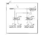
- FIG. 1 is a block diagram showing a configuration of a main part of the processing system 1 in the present embodiment.
- the processing system 1 is mounted on the vehicle C.
- the processing system 1 includes a plurality of individual ECUs 2, an integrated ECU 3, a door motor 40, an actuator 41, and a plurality of sensors 42.
- the plurality of individual ECUs 2 include individual ECUs 2a and 2b.
- the number of each of the individual ECUs 2a and 2b is not limited to 1, and may be 2 or more.
- the door motor 40 and the sensor 42 are connected to the individual ECU 2a.
- the door motor 40 is one of the actuators.
- An actuator 41 and a sensor 42 are connected to the individual ECU 2b.
- Each individual ECU 2 is connected to the integrated ECU 3.
- Each sensor 42 repeatedly acquires vehicle data related to vehicle C.
- the vehicle data shows the acceleration of the vehicle C, the illuminance around the vehicle C, whether or not it is raining, the state of the switch operated by the occupant of the vehicle C, the image around the vehicle C, and the like.
- the type of vehicle data acquired by each of the sensors 42 may be the same as or different from the type of vehicle data acquired by the other sensors 42.
- the sensor 42 outputs the acquired vehicle data to the individual ECU 2 each time the vehicle data is acquired. Each time the vehicle data is input from the sensor 42, the individual ECU 2 transmits the input vehicle data to the integrated ECU 3.
- the door motor 40 locks and unlocks the door of the vehicle C.
- the integrated ECU 3 determines the operation of the door motor 40 or the actuator 41 based on one or more vehicle data received from one or more individual ECUs 2.
- the integrated ECU 3 transmits instruction data indicating the determined operation to at least one individual ECU 2.
- the individual ECU 2a When the individual ECU 2a receives the instruction data from the integrated ECU 3, the individual ECU 2a outputs the received instruction data to the door motor 40.
- the instruction data output to the door motor 40 indicates that the door is locked or unlocked.
- the door motor 40 When the instruction data is input from the individual ECU 2a, the door motor 40 performs the operation indicated by the input instruction data. If the instruction data indicates locking, the door motor 40 locks the door. If the instruction data indicates unlocking, the door motor 40 unlocks the door.
- the individual ECU 2b When the individual ECU 2b receives the instruction data from the integrated ECU 3, the individual ECU 2b outputs the received instruction data to the actuator 41.
- the actuator 41 When the instruction data is input from the individual ECU 2b, the actuator 41 performs the operation indicated by the input instruction data.
- Each of the individual ECU 2a and the integrated ECU 3 functions as a processing device. As described above, the individual ECU 2a executes the process according to the instruction data transmitted by the integrated ECU 3, that is, the instruction of the integrated ECU 3. Therefore, the individual ECU 2a functions as a second processing device.
- the integrated ECU 3 functions as a first processing device. For communication between the individual ECU 2 and the integrated ECU 3, for example, an Ethernet (registered trademark) communication protocol is used.
- the integrated ECU 3 detects a collision of vehicle C based on one or more vehicle data received from one or more individual ECUs 2.
- the integrated ECU 3 transmits collision data indicating the collision of the vehicle C to a plurality of individual ECUs 2 including the individual ECU 2a.
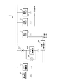
- FIG. 2 is an explanatory diagram of power supply to the integrated ECU 3 and the individual ECU 2.
- the processing system 1 further includes a generator 50, a main capacitor 51, a sub capacitor 52, an ammeter 53, a voltmeter 54, and a power supply management device 55.
- Each of the main power storage device 51 and the sub power storage device 52 is a lead storage battery, a lithium ion battery, a capacitor, or the like.
- Each of the plurality of individual ECUs 2 and the integrated ECU 3 is connected to the positive electrode of the generator 50, the positive electrode of the main capacitor 51, and the ammeter 53.
- Each of the plurality of individual ECUs 2 and the integrated ECU 3 is grounded.
- the negative electrodes of the generator 50 and the main capacitor 51 are also grounded.
- the ammeter 53 is connected to the positive electrode of the sub-capacitor 52 and the power supply management device 55.
- the negative electrode of the sub-capacitor 52 is grounded.
- the voltmeter 54 is connected between the positive electrode and the negative electrode of the sub-capacitor 52.
- the voltmeter 54 is further connected to the power management device 55.
- the power management device 55 is further connected to the integrated ECU 3.
- the generator 50 generates AC power in conjunction with the engine of the vehicle C.
- the generator 50 rectifies the generated AC power into DC power, and outputs the DC voltage related to the rectified DC power from the positive electrode.
- a current flows from the positive electrode of the generator 50 to the individual ECU 2, the integrated ECU 3, the main capacitor 51, and the sub capacitor 52, and power is supplied to these.
- each of the individual ECU 2 and the integrated ECU 3 executes a process using the electric power generated by the generator 50, and the main capacitor 51 and the sub capacitor 52 are charged.
- the sub-capacitor 52 is charged, a current is input to the positive electrode of the sub-capacitor 52 via the ammeter 53.
- the generator 50 When the output voltage of the main capacitor 51 or the sub capacitor 52 is low, the generator 50 generates electricity. As a result, the main capacitor 51 and the sub-capacitor 52 are charged, and the output voltages of the main capacitor 51 and the sub-capacitor 52 are maintained at a voltage equal to or higher than a certain voltage. The electric power consumed by each of the individual ECU 2 and the integrated ECU 3 increases as the amount of processing executed increases.
- the ammeter 53 detects the current value of the current input to the sub-capacitor 52.
- the ammeter 53 detects the current value of the current output from the sub-capacitor 52.
- the ammeter 53 periodically detects the current value.
- the ammeter 53 outputs current data indicating the detected current value to the power supply management device 55.
- the current data indicates, for example, a positive current value.
- the ammeter 53 detects the current value of the current output from the sub-capacitor 52, that is, the current value of the discharge, the current data indicates, for example, a negative current value.
- the voltmeter 54 periodically detects the voltage value between both ends of the sub-capacitor 52. Each time the voltmeter 54 detects a voltage value, the voltmeter 54 outputs voltage data indicating the detected voltage value to the power supply management device 55. The ammeter 53 and the voltmeter 54 detect substantially simultaneously.
- the power supply management device 55 stores the current value indicated by the current data input from the ammeter 53 and the voltage value indicated by the voltage data input from the voltmeter 54.
- the power supply management device 55 stores the current value and the voltage value indicated by the current data and the voltage data input substantially at the same time in association with each other.
- the power supply management device 55 is a capacitor data indicating all the current values and voltage values corresponding to the predetermined number of combinations. Is output to the integrated ECU 3.
- the integrated ECU 3 estimates the degree of deterioration of the sub-capacitor 52 based on the plurality of current values and the plurality of voltage values indicated by the input capacitor data.
- the deterioration of the sub-capacitor 52 is a decrease in the capacity of the sub-capacitor 52.
- the capacity of the sub-capacitor 52 is a capacitance.
- the capacity of the sub-capacitor 52 is the amount of electric power when the sub-capacitor 52 is fully charged.
- the capacity of the sub-capacitor 52 is reduced by, for example, repeated charging and discharging.
- SOH State Of Health
- the amount of electric power stored in the sub-capacitor 52 is referred to as a full charge capacity.
- the full charge capacity of the sub-capacitor 52 is divided by the full charge capacity at the time when the sub-capacitor 52 is manufactured. Multiply the divided value by 100.
- SOH is calculated.
- the unit of SOH is percentage.
- the SOH is estimated based on, for example, the transition of the amount of electric power stored in the sub-capacitor 52.
- the integrated ECU 3 determines the deterioration level of the sub-capacitor 52 based on the estimated degree of deterioration.
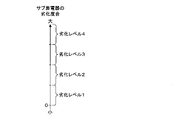
- FIG. 3 is an explanatory diagram of the relationship between the degree of deterioration and the level of deterioration. 1 to 4 are set as the deterioration level of the sub-capacitor 52.
- the range of the degree of deterioration is set for each deterioration level. As shown in FIG. 3, the value within the range of the degree of deterioration corresponding to the deterioration level 1 is the smallest. As the deterioration level increases, so does the value within the range of the degree of deterioration corresponding to the deterioration level.
- the integrated ECU 3 determines the deterioration level of the sub-capacitor 52 to a value to which the estimated deterioration degree belongs.
- the integrated ECU 3 transmits deterioration data indicating the deterioration level of the sub-capacitor 52 to each individual ECU 2.
- a status signal indicating the state of the main capacitor 51 is input to each of the individual ECU 2 and the integrated ECU 3.
- the status signal indicates whether or not the power supply of the main capacitor 51 is interrupted.
- the interruption of the power supply of the main capacitor 51 means, for example, that the connection of the main capacitor 51 is disconnected.
- Each of the positive electrode and the negative electrode of the main capacitor 51 is connected to a terminal (not shown). When at least one of the positive electrode and the negative electrode of the main capacitor 51 is disconnected from the terminal, the connection of the main capacitor 51 is disconnected.
- Whether or not the power supply of the main capacitor 51 is interrupted is determined based on, for example, a current flowing through one of two terminals (not shown) to which the positive electrode and the negative electrode of the main capacitor 51 are connected. For example, when the current flowing through one of the two terminals is zero A, it can be determined that the power supply of the main capacitor 51 is interrupted.
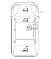
- FIG. 4 is an explanatory diagram of the arrangement of the components in the vehicle C.
- the main capacitor 51 is arranged on the front side in the vehicle C.
- the sub-capacitor 52 is arranged on the rear side in the vehicle C.
- the integrated ECU 3 and the individual ECU 2a are arranged in the center of the vehicle C.
- the door motor 40 is arranged in the vicinity of the door on which the door motor 40 is locked or unlocked. If the vehicle C collides with an object while the vehicle C is traveling, the power supply of the main capacitor 51 may be interrupted.
- each individual ECU 2 executes one of the plurality of first emergency processes.
- Each of the plurality of first emergency processes includes a process of instructing the door motor 40 to unlock the door.
- the integrated ECU 3 detects a collision of the vehicle C based on one or more vehicle data input from one or more individual ECUs 2.
- the integrated ECU 3 detects a collision of the vehicle C, it transmits collision data to each individual ECU 2 and executes one of the plurality of second emergency processes.
- each of the plurality of first emergency processes and the plurality of second emergency processes is a process to be executed when the vehicle C collides with an object. The collision of the vehicle C with an object corresponds to a predetermined condition.
- the integrated ECU 3 When the integrated ECU 3 detects a collision of the vehicle C and the power supply of the main capacitor 51 is interrupted, the integrated ECU 3 has a second emergency corresponding to the degree of deterioration of the sub capacitor 52 in the plurality of second emergency processes. Execute the process.
- each individual ECU 2 executes the first emergency process corresponding to the degree of deterioration of the sub capacitor 52 among the plurality of first emergency processes.
- the capacity of the sub-capacitor 52 is sufficiently smaller than the capacity of the main capacitor 51. Even if a small deterioration occurs in the sub-capacitor 52, the amount of processing executed by using the electric power stored in the sub-capacitor 52 is severely limited. Therefore, the first emergency process and the second emergency process are executed according to the degree of deterioration.
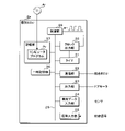
- FIG. 5 is a block diagram showing a configuration of a main part of the individual ECU 2a.
- the individual ECU 2a includes a clock output unit 20, a timer 21, a communication unit 22, an output unit 23, a vehicle data input unit 24, a signal input unit 25, a temporary storage unit 26, a storage unit 27, and a control unit 28. These are connected to the internal bus 29.
- the clock output unit 20 is separately connected to the timer 21 and the control unit 28 in addition to the internal bus 29.
- the communication unit 22 is further connected to the integrated ECU 3.
- the output unit 23 is further connected to the door motor 40.
- the vehicle data input unit 24 is further connected to the sensor 42.
- the clock output unit 20 outputs a clock signal to the control unit 28.
- the clock signal indicates a low level voltage or a high level voltage.
- the voltage indicated by the clock signal periodically switches from the low level voltage to the high level voltage.
- the control unit 28 has a processing element that executes processing, for example, a CPU (Central Processing Unit).
- the processing element of the control unit 28 executes processing each time the voltage indicated by the clock signal is switched from the low level voltage to the high level voltage. In this way, the control unit 28 executes the process in synchronization with the clock signal output by the clock output unit 20.
- the control unit 28 functions as a processing unit and a first processing unit.
- the clock signal is not limited to a signal in which the voltage is periodically switched from the low level voltage to the high level voltage, but is a signal in which the voltage is periodically switched from the high level voltage to the low level voltage. There may be.
- the processing element of the control unit 28 executes processing each time the voltage indicated by the clock signal is switched from the high level voltage to the low level voltage.
- the clock output unit 20 stops the output of the clock signal according to the instruction of the control unit 28.
- the processing element of the control unit 28 stops the execution of the processing.
- the state of the control unit 28 shifts from the operation state in which the process is executed to the sleep state in which the execution of the process is stopped.
- a clock signal output instruction is input from the timer 21 to the clock output unit 20.
- the clock output unit 20 restarts the output of the clock signal.
- the control unit 28 resumes the execution of the process, and the state of the control unit 28 returns from the sleep state to the operating state.
- the control unit 28 instructs the timer 21 to start timing.
- the timer 21 starts timekeeping.
- the time counting time measured by the timer 21 is read out by the control unit 28.
- the control unit 28 instructs the timer 21 to end the clock.
- the timer 21 ends the timekeeping.
- the control unit 28 instructs the timer 21 to start after a predetermined time has elapsed.
- the timer 21 outputs a clock signal output instruction to the clock output unit 20 when a predetermined time has elapsed since the start was instructed.
- the predetermined time is a constant value and is set in advance.
- the communication unit 22 transmits vehicle data to the integrated ECU 3 according to the instructions of the control unit 28.
- the communication unit 22 receives instruction data, collision data, and deterioration data from the integrated ECU 3.
- the output unit 23 outputs instruction data indicating unlocking or locking of the door to the door motor 40 according to the instruction of the control unit 28.
- Vehicle data is repeatedly input from the sensor 42 to the vehicle data input unit 24.
- the control unit 28 acquires vehicle data from the vehicle data input unit 24.
- a status signal is input to the signal input unit 25.
- the temporary storage unit 26 is a volatile memory.
- the control unit 28 writes vehicle data and the like in the temporary storage unit 26.
- the data stored in the temporary storage unit 26 is read out by the control unit 28. When the power supply to the individual ECU 2a is stopped, the data stored in the temporary storage unit 26 is erased.
- the storage unit 27 is a non-volatile memory. The data stored in the storage unit 27 is retained regardless of whether or not power is supplied to the individual ECU 2a.
- the storage unit 27 stores the deterioration level of the sub-capacitor 52.
- the deterioration level stored in the storage unit 27 is changed by the control unit 28.
- the computer program Pr is further stored in the storage unit 27.
- the processing element of the control unit 28 executes the operation control process, the vehicle data transmission process, the first update process, the first selection process, the plurality of first emergency processes, and the like by executing the computer program Pr.
- Each of the plurality of first emergency processes is predetermined in association with the deterioration level of the sub-capacitor 52, that is, the degree of deterioration. Since the number of deterioration levels is 4, the number of first emergency treatments is 4.
- the operation control process is a process for controlling the operation of the door motor 40, that is, the actuator.
- the vehicle data transmission process is a process of transmitting vehicle data.
- the first update process is a process of updating the deterioration level stored in the storage unit 27.
- the first selection process is a process of selecting one first emergency process to be executed from the four first emergency processes corresponding to the deterioration levels 1 to 4. As described above, the first emergency process is a process executed when a collision of the vehicle C is detected.
- the computer program Pr may be stored in the non-temporary storage medium Ar so that the processing element of the control unit 28 can read it.
- the computer program Pr read from the storage medium Ar by a reading device (not shown) is written in the storage unit 27.
- the storage medium Ar is an optical disk, a flexible disk, a magnetic disk, a magnetic disk disk, a semiconductor memory, or the like.
- the optical disk is a CD (Compact Disc) -ROM (Read Only Memory), a DVD (Digital Versatile Disc) -ROM, or a BD (Blu-ray (registered trademark) Disc).
- the magnetic disk is, for example, a hard disk.
- the computer program Pr may be downloaded from an external device (not shown) connected to a communication network (not shown), and the downloaded computer program Pr may be written in the storage unit 27.
- control unit 28 has a plurality of processing elements, the plurality of processing elements cooperate to correspond to the operation control processing, the vehicle data transmission processing, the first update processing, the first selection processing, and the deterioration levels 1 to 4. Execute four first emergency processes and the like.
- the control unit 28 waits until the communication unit 22 receives instruction data from the integrated ECU 3.
- the control unit 28 instructs the output unit 23 to output the instruction data to the door motor 40.
- the door motor 40 locks the door of the vehicle C.
- the instruction data indicates unlocking
- the door motor 40 unlocks the door of the vehicle C.
- the control unit 28 waits again until the communication unit 22 receives the instruction data.
- the control unit 28 stops the execution of the operation control process.
- the vehicle data transmission process, the first update process, the first selection process, and the four first emergency processes corresponding to the deterioration levels 1 to 4 will be described together with various processes of the integrated ECU 3.
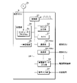
- FIG. 6 is a block diagram showing a configuration of a main part of the integrated ECU 3.
- the integrated ECU 3 includes a clock output unit 30, a timer 31, a plurality of communication units 32, a capacitor data input unit 33, a signal input unit 34, a temporary storage unit 35, a storage unit 36, and a control unit 37. These are connected to the internal bus 38.
- Each of the plurality of communication units 32 is further connected to the individual ECU 2.
- the plurality of communication units 32 include a communication unit 32a connected to the individual ECU 2a and a communication unit 32b connected to the individual ECU 2b.
- the capacitor data input unit 33 is further connected to the power management device 55.
- the clock output unit 30 outputs a clock signal to the control unit 37.
- the voltage of the clock signal is periodically switched from the low level voltage to the high level voltage or from the high level voltage to the low level voltage.
- the control unit 37 has a processing element that executes processing, for example, a CPU.
- the processing element of the control unit 37 executes processing each time the voltage is switched from the low level voltage to the high level voltage or the voltage is switched from the high level voltage to the low level voltage. In this way, the control unit 37 executes the process in synchronization with the clock signal output by the clock output unit 30.
- the control unit 37 functions as a processing unit and a second processing unit.
- the clock output unit 30 stops the output of the clock signal according to the instruction of the control unit 37.
- the processing element of the control unit 37 stops the execution of the processing.
- the state of the control unit 37 transitions from the operating state to the sleep state.
- the clock output unit 30 restarts the output of the clock signal when the preset start condition is satisfied after the output of the clock signal is stopped.
- the control unit 37 instructs the timer 31 to start timing. When the start of timekeeping is instructed, the timer 31 starts timekeeping. The time counting time measured by the timer 31 is read out by the control unit 37. The control unit 37 instructs the timer 31 to end the clock. When the end of timekeeping is instructed, the timer 31 ends the timekeeping.
- the communication unit 32 receives vehicle data from the individual ECU 2.
- the communication unit 32 transmits instruction data, collision data, and deterioration data according to the instructions of the control unit 37.
- the instruction data transmitted by the communication unit 32a indicates that the door is locked or unlocked.
- the instruction data transmitted by the communication unit 32b indicates the operation of the actuator 41.
- Capacitor data is input from the power management device 55 to the capacitor data input unit 33.
- a status signal indicating whether or not the power supply of the main capacitor 51 is interrupted is input to the signal input unit 34.
- the temporary storage unit 35 is a volatile memory.
- the control unit 37 writes vehicle data and the like in the temporary storage unit 35.
- the data stored in the temporary storage unit 35 is read out by the control unit 37.
- the power supply to the integrated ECU 3 is stopped, the data stored in the temporary storage unit 35 is erased.
- the storage unit 36 is a non-volatile memory.
- the data stored in the storage unit 36 is retained regardless of whether or not power is supplied to the integrated ECU 3.
- the storage unit 36 stores the deterioration level of the sub-capacitor 52.
- the deterioration level stored in the storage unit 36 is changed by the control unit 37.
- the computer program Pc is further stored in the storage unit 36.
- the processing element of the control unit 37 executes an instruction data transmission process, a write process, a second update process, a second selection process, a plurality of second emergency processes, and the like by executing the computer program Pc.
- Each of the plurality of second emergency processes is predetermined in association with the deterioration level of the sub-capacitor 52, that is, the degree of deterioration. Since the number of deterioration levels is 4, the number of second emergency treatments is 4.
- the instruction data transmission process is a process of transmitting instruction data to the individual ECU 2.
- the writing process is a process of writing vehicle data to the temporary storage unit 35 or the storage unit 36.
- the second update process is a process of updating the deterioration level stored in the storage unit 36.
- the second selection process is a process of selecting one second emergency process to be executed from the four second emergency processes corresponding to the deterioration levels 1 to 4. As described above, the second emergency process is a process executed when a collision of the vehicle C is detected.
- the computer program Pc may be stored in a non-temporary storage medium Ac so that the processing element of the control unit 37 can read it.
- the computer program Pc read from the storage medium Ac by a reading device (not shown) is written in the storage unit 36.
- the storage medium Ac is an optical disk, a flexible disk, a magnetic disk, a magnetic disk disk, a semiconductor memory, or the like.
- the computer program Pc may be downloaded from an external device (not shown) connected to a communication network (not shown), and the downloaded computer program Pc may be written in the storage unit 36.
- control unit 37 the number of processing elements possessed by the control unit 37 is not limited to 1, and may be 2 or more.
- the plurality of processing elements cooperate with each other to perform instruction data transmission processing, writing processing, second update processing, second selection processing, and four deterioration levels 1 to 4. Execute the second emergency processing, etc.
- the control unit 37 determines the operation of the door motor 40 or the actuator 41 based on the vehicle data received by the communication unit 32.
- the control unit 37 instructs the communication unit 32 to transmit instruction data indicating the determined operation to the individual ECU 2.
- the instruction data indicating the locking or unlocking of the door is transmitted by the communication unit 32a to the communication unit 22 of the individual ECU 2a.
- the control unit 28 of the individual ECU 2a instructs the output unit 23 and the communication unit 22 receives the instruction.
- the instruction data is output to the door motor 40.
- the operation indicated by the instruction data is determined by the control unit 28 of the integrated ECU 3. Therefore, the control unit 28 of the individual ECU 2a executes the process according to the instruction of the control unit 37 of the integrated ECU 3.
- FIG. 7 is a flowchart showing a procedure for transmitting and writing vehicle data.
- the control unit 28 of the individual ECU 2a executes the vehicle data transmission process.
- the control unit 37 of the integrated ECU 3 executes the writing process.
- the control unit 28 of the individual ECU 2a determines whether or not vehicle data has been input from the sensor 42 to the vehicle data input unit 24 (step S1).
- the control unit 28 determines that the vehicle data has not been input (S1: NO)
- the control unit 28 executes step S1 again and waits until the vehicle data is input to the vehicle data input unit 24.
- the control unit 28 determines that the vehicle data has been input (S1: YES)
- the control unit 28 writes the vehicle data input to the vehicle data input unit 24 to the temporary storage unit 26 (step S2).
- step S2 the control unit 28 instructs the communication unit 22 to transmit the vehicle data input to the vehicle data input unit 24 to the communication unit 32a of the integrated ECU 3 (step S3).
- step S3 the control unit 28 ends the vehicle data transmission process.
- the control unit 28 executes the vehicle data transmission process again and waits until the vehicle data is input to the vehicle data input unit 24.
- the individual ECU 2b Similar to the individual ECU 2a, the individual ECU 2b writes the input vehicle data in a temporary storage unit (not shown) when the vehicle data is input from the sensor 42, and transfers the input vehicle data to the communication unit 32b of the integrated ECU 3. Send.
- the control unit 37 of the integrated ECU 3 determines whether or not one of the plurality of communication units 32 has received vehicle data from the individual ECU 2 (step S11). When the control unit 37 determines that none of the plurality of communication units 32 has received the vehicle data (S11: NO), the control unit 37 executes step S11 again, and one of the plurality of communication units 32 receives the vehicle data. Wait until.
- control unit 37 determines that one of the plurality of communication units 32 has received vehicle data from the individual ECU 2 (S11: YES)
- the control unit 37 writes the vehicle data received by the communication unit 32 to the temporary storage unit 35 (step S12). ..
- the control unit 37 determines whether or not to write the vehicle data received by the communication unit 32 to the storage unit 36 (step S13).
- the control unit 37 determines that the vehicle data is to be written (S13: YES)
- the control unit 37 writes the vehicle data received by the communication unit 32 to the storage unit 36 (step S14).
- the control unit 37 ends the writing process when it is determined that the vehicle data is not written (S13: NO) or after the step S14 is executed. After finishing the writing process, the control unit 37 executes the writing process again and waits until one of the plurality of communication units 32 receives the vehicle data.
- the sensor 42 repeatedly outputs vehicle data to the individual ECU 2. Therefore, each individual ECU 2 repeatedly transmits vehicle data to the integrated ECU 3.
- the control unit 37 of the integrated ECU 3 writes vehicle data to the storage unit 36 at predetermined intervals for the vehicle data output by one sensor 42.
- the predetermined number is an integer of 2 or more.
- the control unit 37 of the integrated ECU 3 writes the vehicle data to the storage unit 36, and then does not write the two vehicle data continuously received by the communication unit 32 to the storage unit 36. ..
- FIG. 8 is a flowchart showing the procedure for updating the deterioration level.
- the control unit 28 of the individual ECU 2a executes the first update process.
- the control unit 37 of the integrated ECU 3 executes the second update process.
- the control unit 37 of the integrated ECU 3 determines whether or not the capacitor data has been input from the power management device 55 to the capacitor data input unit 33 (step S21).
- the control unit 37 executes step S21 again and waits until the storage device data is input to the storage device data input unit 33.
- the control unit 37 determines that the capacitor data has been input (S21: YES)
- the control unit 37 of the sub-capacitor 52 is based on a plurality of current values and a plurality of voltage values indicated by the capacitor data input to the capacitor data input unit 33.
- the degree of deterioration is estimated (step S22).
- the control unit 37 updates the deterioration level stored in the storage unit 36 to a deterioration level corresponding to the degree of deterioration estimated in step S22 (step S23).
- the control unit 37 instructs each communication unit 22 to transmit the deterioration data indicating the deterioration level updated in step S23 to the individual ECU 2 connected to the communication unit 22 (step S24).
- the control unit 37 ends the second update process after executing step S24. After completing the second update process, the control unit 37 executes the second update process again and waits until the capacitor data is input to the capacitor data input unit 33.
- the power management device 55 repeatedly outputs the capacitor data to the integrated ECU 3. Therefore, the integrated ECU 3 repeatedly transmits deterioration data to each individual ECU 2.
- the control unit 28 of the individual ECU 2a determines whether or not the communication unit 22 has received deterioration data from the communication unit 32a of the integrated ECU 3 (step S31).
- the control unit 28 executes step S31 again and waits until the communication unit 22 receives the deterioration data.
- the control unit 28 determines that the communication unit 22 has received the deterioration data (S31: YES)
- the control unit 28 updates the deterioration level stored in the storage unit 27 to the deterioration level indicated by the deterioration data received by the communication unit 22. (Step S32).
- the control unit 28 ends the first update process after executing step S32. After completing the first update process, the control unit 28 executes the first update process again and waits until the communication unit 22 receives the deteriorated data.
- the deterioration level is stored in the non-volatile storage unit of the individual ECU 2b.
- the individual ECU 2b receives deterioration data from the communication unit 32b of the integrated ECU 3 in the same manner as the individual ECU 2a.
- the individual ECU 2b updates the deterioration level stored in the storage unit to the deterioration level indicated by the received deterioration data.
- the deterioration level stored in each individual ECU 2 and the integrated ECU 3 is updated to a level corresponding to the degree of deterioration estimated by the control unit 37 of the integrated ECU 3.
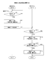
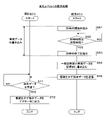
- FIG. 9 is a flowchart showing the procedure for selecting emergency processing.
- the control unit 28 of the individual ECU 2a executes the first selection process.
- the control unit 37 of the integrated ECU 3 executes the second emergency process.
- the first selection process and the second selection process are executed, for example, when the ignition switch of the vehicle C is switched on.
- the control unit 37 of the integrated ECU 3 determines whether or not the vehicle C has collided with an object, for example, based on one or more vehicle data received by one or more communication units 22 (. Step S41). For the determination of the collision, for example, vehicle data showing the acceleration of the vehicle C is used. When the control unit 37 determines that the vehicle C has not collided with the object (S41: NO), the control unit 37 executes step S41 again and waits until the vehicle C collides with the object.
- control unit 37 determines whether or not the power supply of the main capacitor 51 is interrupted based on the state signal input to the signal input unit 34 (step S43).
- control unit 37 reads the deterioration level from the storage unit 36 (step S44), and executes the second emergency process corresponding to the read deterioration level. (Step S45). After executing step S45, the control unit 37 ends the second selection process.
- control unit 37 determines that the power supply of the main capacitor 51 is not interrupted (S43: NO)
- the control unit 37 executes the second emergency process corresponding to the deterioration level 1 (step S46), and ends the second selection process. do.
- the control unit 28 of the individual ECU 2a determines whether or not the communication unit 22 has received collision data from the communication unit 32a of the integrated ECU 3 (step S51).
- the control unit 28 executes step S51 again and waits until the communication unit 22 receives the collision data.
- step S52 When the control unit 28 determines that the communication unit 22 has received the collision data (S51: YES), whether or not the power supply of the main capacitor 51 is interrupted based on the state signal input to the signal input unit 25. Is determined (step S52). When the control unit 28 determines that the power supply of the main capacitor 51 is interrupted (S52: YES), the control unit 28 reads the deterioration level from the storage unit 27 (step S53), and executes the first emergency process corresponding to the read deterioration level. (Step S54). After executing step S54, the control unit 28 ends the first selection process.
- control unit 28 determines that the power supply of the main capacitor 51 is not interrupted (S52: NO)
- the control unit 28 executes the first emergency process corresponding to the deterioration level 1 (step S55), and ends the first selection process. do.
- the individual ECU 2b receives collision data in the same manner as the individual ECU 2a.
- the individual ECU 2b determines whether or not the power supply of the main capacitor 51 is interrupted based on the state signal.
- the individual ECU 2b determines that the power supply of the main capacitor 51 is interrupted, the individual ECU 2b executes the first emergency process corresponding to the deterioration level stored in the storage unit.
- the deterioration level is 1, the individual ECU 2b does not execute the process related to the collision of the vehicle C. Therefore, when it is determined that the power supply of the main capacitor 51 is not interrupted, the individual ECU 2b does not execute the process related to the collision of the vehicle C.
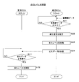
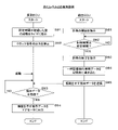
- FIG. 10 is a flowchart showing a procedure for emergency processing of deterioration level 1.
- the control unit 28 of the individual ECU 2a is set in steps S54 and S55 of the first selection process.
- the first emergency process corresponding to the deterioration level 1 is executed.
- the control unit 37 of the integrated ECU 3 executes the second emergency process corresponding to the deterioration level 1 in the steps S45 and S46 of the second selection process.
- step S61 the control unit 37 of the integrated ECU 3 instructs the timer 31 to start timing.
- step S62 the control unit 37 determines whether or not the time counting time measured by the timer 31 is equal to or longer than a predetermined time.
- step S62 the control unit 37 executes step S62 again and waits until the time measuring time reaches the predetermined time.
- the control unit 37 determines that the timing time is equal to or longer than the predetermined time (S62: YES)
- the control unit 37 instructs the timer 31 to end the timing (step S63).
- the timer 31 ends the timing.
- the control unit 37 waits until a predetermined time elapses after executing the second emergency process of deterioration level 1. During this period, each individual ECU 2 repeatedly transmits vehicle data, and the integrated ECU 3 writes vehicle data received from each individual ECU 2 in the temporary storage unit 35 (see FIG. 7).
- step S63 the control unit 37 of the integrated ECU 3 writes a plurality of vehicle data stored in the volatile temporary storage unit 35 into the non-volatile storage unit 36 (step S64). These vehicle data are used, for example, to grasp the situation in which the vehicle C collides with an object.
- step S64 the control unit 37 instructs the communication unit 32a to transmit instruction data indicating unlocking to the communication unit 22 of the individual ECU 2a (step S65).
- step S65 the control unit 37 ends the second emergency process of deterioration level 1.
- the control unit 28 of the individual ECU 2a determines whether or not the communication unit 22 has received the instruction data from the communication unit 32a of the integrated ECU 3 (step S71). When the control unit 28 determines that the instruction data has not been received (S71: NO), the control unit 28 executes step S71 again and waits until the communication unit 22 receives the instruction data.
- the control unit 28 executes vehicle data transmission processing in parallel with the first emergency processing of deterioration level 1. Therefore, the individual ECU 2a repeatedly transmits the vehicle data to the integrated ECU 3 while waiting for the reception of the instruction data.
- the control unit 28 of the individual ECU 2a may end the vehicle data transmission process after a predetermined time has elapsed from the detection of the collision of the vehicle C.
- step S72 the control unit 28 instructs the output unit 23 to output the instruction data indicating unlocking to the door motor 40 (step S72).
- the door motor 40 unlocks the door of the vehicle C.
- step S72 the control unit 28 ends the first emergency process of deterioration level 1. Instructing the output unit 23 to output the instruction data indicating unlocking to the door motor 40 corresponds to instructing the unlocking of the door of the vehicle C.
- the individual ECU 2b does not execute the process related to the collision of the vehicle C when the deterioration level is 1.
- the individual ECU 2b repeatedly transmits vehicle data to the integrated ECU 3.
- the individual ECU 2b may end the transmission of vehicle data after a predetermined time has elapsed from the detection of the collision of the vehicle C.
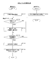
- FIG. 11 is a flowchart showing the procedure of emergency processing of deterioration level 2.
- the control unit 28 of the individual ECU 2a executes the first emergency process corresponding to the deterioration level 2 in step S54 of the first selection process.
- the control unit 37 of the integrated ECU 3 executes the second emergency process corresponding to the deterioration level 2 in step S45 of the second selection process.
- the control unit 37 of the integrated ECU 3 instructs the timer 31 to start timing (step S81). As a result, the timer 31 starts timing.
- the control unit 37 determines whether or not the time counting time measured by the timer 31 is equal to or longer than a predetermined time (step S82). When the control unit 37 determines that the time counting time is less than the predetermined time (S82: NO), the control unit 37 executes step S82 again and waits until the time measuring time reaches the predetermined time.
- the control unit 37 determines that the timing time is equal to or longer than the predetermined time (S82: YES)
- the control unit 37 instructs the timer 31 to end the timing (step S83).
- the timer 31 ends the timing.
- the control unit 37 waits until a predetermined time elapses after executing the second emergency process of the deterioration level 2. During this period, as will be described later, the state of each individual ECU 2 is a sleep state, and vehicle data is not transmitted from each individual ECU 2 to the integrated ECU 3.
- step S83 the control unit 37 of the integrated ECU 3 writes a plurality of vehicle data stored in the volatile temporary storage unit 35 into the non-volatile storage unit 36 (step S84). These vehicle data are used, for example, to grasp the situation in which the vehicle C collides with an object.
- step S84 the control unit 37 instructs the communication unit 32a to transmit instruction data indicating unlocking to the communication unit 22 of the individual ECU 2a (step S85).
- step S85 the control unit 37 ends the second emergency process of deterioration level 2.
- the control unit 28 of the individual ECU 2a instructs the timer 21 to start after a predetermined time has elapsed (step S91), instructs the clock output unit 20, and outputs the clock signal. Is stopped (step S92).
- the control unit 28 stops processing, and the state of the control unit 28 transitions to the sleep state.
- the control unit 28 does not execute the vehicle data transmission process from the transition of the state of the control unit 28 to the sleep state to the end of the first emergency process of the deterioration level 2.
- the timer 21 outputs a clock signal output instruction to the clock output unit 20, the control unit 28 is activated, and the state of the control unit 28 changes from the sleep state to the operating state.
- control unit 28 determines whether or not the communication unit 22 has received instruction data from the communication unit 32a of the integrated ECU 3 (step S93). When the control unit 28 determines that the instruction data has not been received (S93: NO), the control unit 28 executes step S93 again and waits until the communication unit 22 receives the instruction data.
- control unit 28 determines that the communication unit 22 has received the instruction data (S93: YES)
- the control unit 28 instructs the output unit 23 to output the instruction data indicating unlocking to the door motor 40 (step S94).
- the door motor 40 unlocks the door of the vehicle C.
- the control unit 28 ends the first emergency process of deterioration level 2.
- the individual ECU 2b stops the output of the clock signal.
- the control unit (not shown) that executes the process stops operating, and the state of the control unit transitions to the sleep state. After that, the state of the control unit of the individual ECU 2b is maintained in the sleep state at least until the control unit 28 of the individual ECU 2a completes the first emergency process of the deterioration level 2.
- FIG. 12 is a flowchart showing the procedure of emergency processing of deterioration level 3.
- the control unit 28 of the individual ECU 2a executes the first emergency process corresponding to the deterioration level 3 in step S54 of the first selection process.
- the control unit 37 of the integrated ECU 3 executes the second emergency process corresponding to the deterioration level 3 in step S45 of the second selection process.
- step S101 the control unit 37 of the integrated ECU 3 instructs the clock output unit 30 to stop the output of the clock signal.
- the control unit 37 stops processing, and the state of the control unit 37 transitions to the sleep state.
- the state of the control unit 37 is maintained in a sleep state at least until the control unit 28 of the individual ECU 2a finishes the first emergency process of the deterioration level 3.
- step S101 the control unit 37 ends the second emergency process of deterioration level 3.
- the control unit 28 of the individual ECU 2a stops the vehicle data transmission process when the first emergency process of the deterioration level 3 is executed.
- the control unit 28 instructs the timer 21 to start timing (step S111).
- the timer 21 starts timing.
- the control unit 28 determines whether or not vehicle data has been input from the sensor 42 to the vehicle data input unit 24 (step S112).
- control unit 28 determines that the vehicle data has been input (S112: YES)
- the control unit 28 writes the vehicle data input to the vehicle data input unit 24 to the non-volatile storage unit 27 (step S113).
- the control unit 28 determines that the vehicle data has not been input (S112: NO), or after executing step S113, the control unit 28 determines whether or not the time counting time measured by the timer 21 is equal to or longer than a predetermined time. Determination (step S114).
- step S112 When the control unit 28 determines that the time counting time is less than the predetermined time (S114: NO), the control unit 28 executes step S112 again.
- the vehicle data input from the sensor 42 is repeatedly written to the storage unit 27 until the time counting time of the timer 21 reaches a predetermined time.
- the control unit 28 determines that the timing time is equal to or longer than a predetermined time (S114: YES)
- the control unit 28 instructs the timer 21 to end the timing (step S115). As a result, the timer 21 ends the timing.
- step S115 the control unit 28 instructs the output unit 23 to output instruction data indicating unlocking to the door motor 40 (step S116). As a result, the door motor 40 unlocks the door of the vehicle C.
- step S116 the control unit 28 ends the first emergency process of deterioration level 3.
- the individual ECU 2b In the first emergency process of deterioration level 3, the individual ECU 2b repeatedly writes the vehicle data input from the sensor 42 to the non-volatile storage unit from the start of the first emergency process until a predetermined time elapses. After that, the control unit of the individual ECU 2b ends the first emergency process of the deterioration level 3.
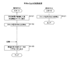
- FIG. 13 is a flowchart showing the procedure of emergency processing of deterioration level 4.
- the control unit 28 of the individual ECU 2a executes the first emergency process corresponding to the deterioration level 4 in step S54 of the first selection process.
- the control unit 37 of the integrated ECU 3 executes the second emergency process corresponding to the deterioration level 4 in step S45 of the second selection process.
- the control unit 37 of the integrated ECU 3 instructs the clock output unit 30 to stop the output of the clock signal (step S121).
- the control unit 37 stops processing, and the state of the control unit 37 transitions to the sleep state.
- the state of the control unit 37 is maintained in a sleep state at least until the control unit 28 of the individual ECU 2a finishes the first emergency process of the deterioration level 4.
- the control unit 37 ends the second emergency process of deterioration level 3.
- the control unit 28 of the individual ECU 2a instructs the timer 21 to start after a predetermined time has elapsed (step S131), instructs the clock output unit 20, and outputs the clock signal. Is stopped (step S132). As a result, the control unit 28 stops processing, and the state of the control unit 28 transitions to the sleep state. The control unit 28 does not execute the vehicle data transmission process from the transition of the state of the control unit 28 to the sleep state to the end of the first emergency process of the deterioration level 4.
- the timer 21 outputs a clock signal output instruction to the clock output unit 20, the control unit 28 is activated, and the state of the control unit 28 changes from the sleep state to the operating state.
- control unit 28 instructs the output unit 23 to output the instruction data indicating unlocking to the door motor 40 (step S133). As a result, the door motor 40 unlocks the door of the vehicle C. After executing step S133, the control unit 28 ends the first emergency process of deterioration level 4.
- control unit 28 of the individual ECU 2a and the control unit of the individual ECU 2b execute the first emergency process corresponding to the deterioration level of the sub-capacitor 52.
- the control unit 37 of the integrated ECU 3 executes the second emergency process corresponding to the deterioration level of the sub-capacitor 52. Therefore, when the vehicle C collides, it is possible to realize a configuration in which a high priority process, that is, a process of unlocking the door of the vehicle C is appropriately executed.
- the control unit 37 of the integrated ECU 3 writes the vehicle data stored in the temporary storage unit 35 into the storage unit 36. .. Not only high-priority processing but also low-priority processing is executed. Regarding the writing of vehicle data, the smaller the deterioration level, the larger the number of vehicle data to be written in the storage unit 36.
- the control unit 28 of the individual ECU 2a stops the execution of the process.
- the control unit 37 of the integrated ECU 3 stops the execution of the process. As a result, the door is properly unlocked by the individual ECU 2a.
- the timing for determining whether or not the power supply of the sub-capacitor 52 is interrupted is not limited to the timing at which the vehicle C collides.
- the predetermined condition is that there is no problem as long as a phenomenon that the power supply of the main capacitor 51 may be interrupted occurs.
- the high priority process is not limited to the process of unlocking the door.
- the operations performed by the plurality of individual ECUs 2 and the integrated ECU 3 as a whole are not limited to unlocking the door of the vehicle C and writing vehicle data.
- the deterioration of the sub-capacitor 52 is not limited to the decrease in the capacity of the sub-capacitor 52, and may be an increase in the internal resistance value of the sub-capacitor 52.
- the internal resistance value of the sub-capacitor 52 is also calculated based on a plurality of current values and a plurality of voltage values indicated by the capacitor data.
- the control unit 28 of the individual ECU 2a may write the vehicle data stored in the temporary storage unit 26 to the storage unit 27.
- the method by which the control unit 37 of the integrated ECU 3 detects the collision of the vehicle C is not limited to the method of detecting the collision based on one or more vehicle data.
- the collision of the vehicle C may be detected based on whether or not the collision signal is input.
- the control unit 28 of the individual ECU 2a collides with the object in the first selection process based on whether or not the collision signal is input in step S51. It may be determined whether or not.
- control unit 28 determines that the vehicle C has not collided with the object
- the control unit 28 waits until the vehicle C collides with the object.
- the control unit 28 determines that the vehicle C has collided with an object
- the control unit 28 executes step S52.
- the individual ECU 2b may determine whether or not the vehicle C has collided with an object, similarly to the individual ECU 2a.
- the number of deterioration levels is not limited to 4, and may be 2, 3 or 5 or more.
- the number of each of the first emergency treatment and the second emergency treatment matches the number of deterioration levels.
- the number of door motors 40 or actuators 41 connected to each individual ECU 2 is not limited to 1, and may be 2 or more.
- the number of sensors 42 connected to each individual ECU 2 is not limited to 1, and may be 2 or more.
- Each of the plurality of individual ECUs 2 and the integrated ECU 3 may be connected by a bus.
- a communication protocol of CAN Controller Area Network
- Each of the individual ECUs 2a and 2b may have a function of distributing electric power to a plurality of electric devices such as a door motor 40, an actuator 41, or a sensor 42.
- the processing element included in the control unit 37 of the integrated ECU 3 may be a vehicle computer.
Landscapes
- Engineering & Computer Science (AREA)
- Power Engineering (AREA)
- Mechanical Engineering (AREA)
- Chemical & Material Sciences (AREA)
- Physics & Mathematics (AREA)
- General Physics & Mathematics (AREA)
- Transportation (AREA)
- Combustion & Propulsion (AREA)
- Manufacturing & Machinery (AREA)
- Chemical Kinetics & Catalysis (AREA)
- General Chemical & Material Sciences (AREA)
- Electrochemistry (AREA)
- Secondary Cells (AREA)
- Charge And Discharge Circuits For Batteries Or The Like (AREA)
- Electric Propulsion And Braking For Vehicles (AREA)
- Health & Medical Sciences (AREA)
- General Health & Medical Sciences (AREA)
- Medical Informatics (AREA)
Priority Applications (2)
| Application Number | Priority Date | Filing Date | Title |
|---|---|---|---|
| US18/247,513 US20230373415A1 (en) | 2020-10-06 | 2021-07-27 | Processing apparatus, processing system, and processing method |
| CN202180065557.1A CN116325288A (zh) | 2020-10-06 | 2021-07-27 | 处理装置、处理系统及处理方法 |
Applications Claiming Priority (2)
| Application Number | Priority Date | Filing Date | Title |
|---|---|---|---|
| JP2020169222A JP7367651B2 (ja) | 2020-10-06 | 2020-10-06 | 処理装置、処理システム及び処理方法 |
| JP2020-169222 | 2020-10-06 |
Publications (1)
| Publication Number | Publication Date |
|---|---|
| WO2022074902A1 true WO2022074902A1 (ja) | 2022-04-14 |
Family
ID=81126437
Family Applications (1)
| Application Number | Title | Priority Date | Filing Date |
|---|---|---|---|
| PCT/JP2021/027701 Ceased WO2022074902A1 (ja) | 2020-10-06 | 2021-07-27 | 処理装置、処理システム及び処理方法 |
Country Status (4)
| Country | Link |
|---|---|
| US (1) | US20230373415A1 (cg-RX-API-DMAC7.html) |
| JP (1) | JP7367651B2 (cg-RX-API-DMAC7.html) |
| CN (1) | CN116325288A (cg-RX-API-DMAC7.html) |
| WO (1) | WO2022074902A1 (cg-RX-API-DMAC7.html) |
Families Citing this family (1)
| Publication number | Priority date | Publication date | Assignee | Title |
|---|---|---|---|---|
| JP7896584B2 (ja) * | 2023-10-03 | 2026-07-29 | トヨタ自動車株式会社 | 電源システム |
Citations (8)
| Publication number | Priority date | Publication date | Assignee | Title |
|---|---|---|---|---|
| JPH07191701A (ja) * | 1993-12-27 | 1995-07-28 | Nippondenso Co Ltd | 車載用演算装置の電源供給装置 |
| JP2008500223A (ja) * | 2004-05-28 | 2008-01-10 | カテム・デヴェレック・ゲゼルシャフト・ミット・ベシュレンクテル・ハフツング | 電子式バッテリ安全スイッチ |
| JP2009144441A (ja) * | 2007-12-14 | 2009-07-02 | Mitsubishi Cable Ind Ltd | 車両用ドアロックシステム |
| JP2010254069A (ja) * | 2009-04-23 | 2010-11-11 | Toyota Motor Corp | 車両用電源制御装置、車両用電源制御方法 |
| JP2014033533A (ja) * | 2012-08-03 | 2014-02-20 | Panasonic Corp | バックアップ電源装置およびこれを用いた自動車 |
| WO2018056190A1 (ja) * | 2016-09-20 | 2018-03-29 | パナソニックIpマネジメント株式会社 | 電源装置および電源装置を搭載した車両 |
| JP2020124039A (ja) * | 2019-01-30 | 2020-08-13 | 株式会社今仙電機製作所 | 車両用補助電源装置及び電力供給方法 |
| JP2020182316A (ja) * | 2019-04-25 | 2020-11-05 | 矢崎総業株式会社 | 冗長電源システム |
Family Cites Families (6)
| Publication number | Priority date | Publication date | Assignee | Title |
|---|---|---|---|---|
| CN200968986Y (zh) * | 2006-09-06 | 2007-10-31 | 赵光平 | 多功能gps车载系统 |
| US9013056B2 (en) * | 2012-02-22 | 2015-04-21 | Panasonic Intellectual Property Management Co., Ltd. | Backup power source device and automobile equipped with same |
| JP5842907B2 (ja) * | 2013-12-26 | 2016-01-13 | トヨタ自動車株式会社 | 電源制御装置、電源制御方法 |
| JP2019201464A (ja) * | 2018-05-15 | 2019-11-21 | 日立化成株式会社 | 劣化診断システム、及び劣化診断方法 |
| JP2020032831A (ja) * | 2018-08-29 | 2020-03-05 | 矢崎総業株式会社 | 車両電源システム |
| JP7204509B2 (ja) * | 2019-02-05 | 2023-01-16 | 株式会社Subaru | 車両 |
-
2020
- 2020-10-06 JP JP2020169222A patent/JP7367651B2/ja active Active
-
2021
- 2021-07-27 CN CN202180065557.1A patent/CN116325288A/zh active Pending
- 2021-07-27 US US18/247,513 patent/US20230373415A1/en active Pending
- 2021-07-27 WO PCT/JP2021/027701 patent/WO2022074902A1/ja not_active Ceased
Patent Citations (8)
| Publication number | Priority date | Publication date | Assignee | Title |
|---|---|---|---|---|
| JPH07191701A (ja) * | 1993-12-27 | 1995-07-28 | Nippondenso Co Ltd | 車載用演算装置の電源供給装置 |
| JP2008500223A (ja) * | 2004-05-28 | 2008-01-10 | カテム・デヴェレック・ゲゼルシャフト・ミット・ベシュレンクテル・ハフツング | 電子式バッテリ安全スイッチ |
| JP2009144441A (ja) * | 2007-12-14 | 2009-07-02 | Mitsubishi Cable Ind Ltd | 車両用ドアロックシステム |
| JP2010254069A (ja) * | 2009-04-23 | 2010-11-11 | Toyota Motor Corp | 車両用電源制御装置、車両用電源制御方法 |
| JP2014033533A (ja) * | 2012-08-03 | 2014-02-20 | Panasonic Corp | バックアップ電源装置およびこれを用いた自動車 |
| WO2018056190A1 (ja) * | 2016-09-20 | 2018-03-29 | パナソニックIpマネジメント株式会社 | 電源装置および電源装置を搭載した車両 |
| JP2020124039A (ja) * | 2019-01-30 | 2020-08-13 | 株式会社今仙電機製作所 | 車両用補助電源装置及び電力供給方法 |
| JP2020182316A (ja) * | 2019-04-25 | 2020-11-05 | 矢崎総業株式会社 | 冗長電源システム |
Also Published As
| Publication number | Publication date |
|---|---|
| US20230373415A1 (en) | 2023-11-23 |
| JP7367651B2 (ja) | 2023-10-24 |
| JP2022061302A (ja) | 2022-04-18 |
| CN116325288A (zh) | 2023-06-23 |
Similar Documents
| Publication | Publication Date | Title |
|---|---|---|
| JP5567956B2 (ja) | 複数組電池のセル電圧均等化装置 | |
| CN115202681B (zh) | 车载软件更新方法和车载系统 | |
| US8587257B2 (en) | Secondary battery device and vehicle | |
| JP4543714B2 (ja) | 組電池の容量調整装置および容量調整方法 | |
| EP3032690B1 (en) | Battery control system and vehicle control system | |
| JP5091473B2 (ja) | 組電池制御方法、組電池制御回路、及びこれを備えた充電回路、電池パック | |
| KR20120076068A (ko) | 이차전지 셀의 퇴화 정도를 반영한 배터리 팩의 관리 장치와 방법 및 이를 구비한 배터리 팩 | |
| JP7207817B2 (ja) | バッテリー管理方法、バッテリー装置、およびバッテリーを含む自動車 | |
| CN104553844A (zh) | 车辆和用于控制车辆中的电池的方法 | |
| JP2008154317A5 (cg-RX-API-DMAC7.html) | ||
| JP2002246073A (ja) | 組電池の異常検出装置 | |
| JP2002101565A (ja) | 組電池の電圧調整装置及び組電池の電圧調整方法 | |
| JP2003304646A (ja) | 組電池の電圧検出装置 | |
| CN115923588B (zh) | 单电池均衡系统 | |
| JP2021141722A (ja) | 電池制御装置および電池制御方法 | |
| JP7367651B2 (ja) | 処理装置、処理システム及び処理方法 | |
| US10131244B2 (en) | Method for monitoring a battery | |
| CN114270593A (zh) | 电池系统,电池管理方法 | |
| WO2017068874A1 (ja) | 車載用電源装置 | |
| JP5908903B2 (ja) | バッテリの充電状態を決定する方法 | |
| WO2015022731A1 (ja) | 電池監視装置、電池システムおよび車両制御システム | |
| CN118488902A (zh) | 用于均衡电池的蓄电池单元的电荷的电池管理系统和方法 | |
| JP4003798B2 (ja) | 車両用電源装置 | |
| JP2013081306A (ja) | 電池劣化均等化システムおよび方法 | |
| JP2002354703A (ja) | 車両用二次電池制御装置 |
Legal Events
| Date | Code | Title | Description |
|---|---|---|---|
| 121 | Ep: the epo has been informed by wipo that ep was designated in this application |
Ref document number: 21877206 Country of ref document: EP Kind code of ref document: A1 |
|
| NENP | Non-entry into the national phase |
Ref country code: DE |
|
| 122 | Ep: pct application non-entry in european phase |
Ref document number: 21877206 Country of ref document: EP Kind code of ref document: A1 |