WO2022071530A1 - Copolymère, corps moulé par injection, et élément à comprimer - Google Patents
Copolymère, corps moulé par injection, et élément à comprimer Download PDFInfo
- Publication number
- WO2022071530A1 WO2022071530A1 PCT/JP2021/036301 JP2021036301W WO2022071530A1 WO 2022071530 A1 WO2022071530 A1 WO 2022071530A1 JP 2021036301 W JP2021036301 W JP 2021036301W WO 2022071530 A1 WO2022071530 A1 WO 2022071530A1
- Authority
- WO
- WIPO (PCT)
- Prior art keywords
- copolymer
- present disclosure
- compressed
- temperature
- electrolytic solution
- Prior art date
Links
- 229920001577 copolymer Polymers 0.000 title claims abstract description 175
- 238000002347 injection Methods 0.000 title claims description 13
- 239000007924 injection Substances 0.000 title claims description 13
- BFKJFAAPBSQJPD-UHFFFAOYSA-N tetrafluoroethene Chemical group FC(F)=C(F)F BFKJFAAPBSQJPD-UHFFFAOYSA-N 0.000 claims abstract description 46
- 125000000524 functional group Chemical group 0.000 claims abstract description 41
- 239000000178 monomer Substances 0.000 claims abstract description 15
- 239000000155 melt Substances 0.000 claims abstract description 13
- 125000004432 carbon atom Chemical group C* 0.000 claims abstract description 8
- KHXKESCWFMPTFT-UHFFFAOYSA-N 1,1,1,2,2,3,3-heptafluoro-3-(1,2,2-trifluoroethenoxy)propane Chemical group FC(F)=C(F)OC(F)(F)C(F)(F)C(F)(F)F KHXKESCWFMPTFT-UHFFFAOYSA-N 0.000 claims description 52
- 239000011247 coating layer Substances 0.000 claims description 24
- 235000012438 extruded product Nutrition 0.000 claims description 2
- 125000001153 fluoro group Chemical group F* 0.000 abstract description 7
- 238000012360 testing method Methods 0.000 description 80
- OKKJLVBELUTLKV-UHFFFAOYSA-N Methanol Chemical compound OC OKKJLVBELUTLKV-UHFFFAOYSA-N 0.000 description 72
- 239000008151 electrolyte solution Substances 0.000 description 53
- 239000008188 pellet Substances 0.000 description 39
- 238000000034 method Methods 0.000 description 38
- 239000000047 product Substances 0.000 description 36
- 230000006835 compression Effects 0.000 description 34
- 238000007906 compression Methods 0.000 description 34
- 238000006116 polymerization reaction Methods 0.000 description 33
- 238000007789 sealing Methods 0.000 description 31
- 239000007789 gas Substances 0.000 description 29
- -1 perfluoro Chemical group 0.000 description 29
- XLYOFNOQVPJJNP-UHFFFAOYSA-N water Substances O XLYOFNOQVPJJNP-UHFFFAOYSA-N 0.000 description 29
- 239000010408 film Substances 0.000 description 27
- 230000035699 permeability Effects 0.000 description 27
- 229910052731 fluorine Inorganic materials 0.000 description 26
- 239000000463 material Substances 0.000 description 25
- 239000011737 fluorine Substances 0.000 description 23
- 238000000465 moulding Methods 0.000 description 21
- 239000010410 layer Substances 0.000 description 20
- 150000002978 peroxides Chemical class 0.000 description 20
- 239000011255 nonaqueous electrolyte Substances 0.000 description 18
- 239000011162 core material Substances 0.000 description 16
- 238000005259 measurement Methods 0.000 description 15
- 238000001125 extrusion Methods 0.000 description 14
- 239000000126 substance Substances 0.000 description 14
- YCKRFDGAMUMZLT-UHFFFAOYSA-N Fluorine atom Chemical compound [F] YCKRFDGAMUMZLT-UHFFFAOYSA-N 0.000 description 13
- 239000011248 coating agent Substances 0.000 description 13
- 238000000576 coating method Methods 0.000 description 13
- 230000009477 glass transition Effects 0.000 description 13
- 238000001746 injection moulding Methods 0.000 description 13
- 238000003860 storage Methods 0.000 description 13
- 238000012546 transfer Methods 0.000 description 13
- 238000010521 absorption reaction Methods 0.000 description 12
- 239000007788 liquid Substances 0.000 description 12
- 229920000642 polymer Polymers 0.000 description 12
- 239000011521 glass Substances 0.000 description 11
- 238000010438 heat treatment Methods 0.000 description 11
- 239000000523 sample Substances 0.000 description 11
- 238000002844 melting Methods 0.000 description 10
- 230000008018 melting Effects 0.000 description 10
- 230000005540 biological transmission Effects 0.000 description 9
- 239000004020 conductor Substances 0.000 description 9
- 238000005187 foaming Methods 0.000 description 9
- 238000012856 packing Methods 0.000 description 9
- 239000000243 solution Substances 0.000 description 9
- 239000002904 solvent Substances 0.000 description 9
- IEJIGPNLZYLLBP-UHFFFAOYSA-N dimethyl carbonate Chemical compound COC(=O)OC IEJIGPNLZYLLBP-UHFFFAOYSA-N 0.000 description 8
- 239000003792 electrolyte Substances 0.000 description 8
- 238000003682 fluorination reaction Methods 0.000 description 8
- 239000000446 fuel Substances 0.000 description 8
- 239000000203 mixture Substances 0.000 description 8
- YPVDWEHVCUBACK-UHFFFAOYSA-N propoxycarbonyloxy propyl carbonate Chemical compound CCCOC(=O)OOC(=O)OCCC YPVDWEHVCUBACK-UHFFFAOYSA-N 0.000 description 8
- 239000003566 sealing material Substances 0.000 description 8
- 238000005260 corrosion Methods 0.000 description 7
- 235000013305 food Nutrition 0.000 description 7
- 238000004519 manufacturing process Methods 0.000 description 7
- 238000001228 spectrum Methods 0.000 description 7
- RYGMFSIKBFXOCR-UHFFFAOYSA-N Copper Chemical compound [Cu] RYGMFSIKBFXOCR-UHFFFAOYSA-N 0.000 description 6
- 229910052782 aluminium Inorganic materials 0.000 description 6
- XAGFODPZIPBFFR-UHFFFAOYSA-N aluminium Chemical compound [Al] XAGFODPZIPBFFR-UHFFFAOYSA-N 0.000 description 6
- 239000012986 chain transfer agent Substances 0.000 description 6
- 230000000052 comparative effect Effects 0.000 description 6
- 150000001875 compounds Chemical class 0.000 description 6
- 230000007797 corrosion Effects 0.000 description 6
- IJGRMHOSHXDMSA-UHFFFAOYSA-N Atomic nitrogen Chemical compound N#N IJGRMHOSHXDMSA-UHFFFAOYSA-N 0.000 description 5
- OIFBSDVPJOWBCH-UHFFFAOYSA-N Diethyl carbonate Chemical compound CCOC(=O)OCC OIFBSDVPJOWBCH-UHFFFAOYSA-N 0.000 description 5
- LFQSCWFLJHTTHZ-UHFFFAOYSA-N Ethanol Chemical compound CCO LFQSCWFLJHTTHZ-UHFFFAOYSA-N 0.000 description 5
- KMTRUDSVKNLOMY-UHFFFAOYSA-N Ethylene carbonate Chemical compound O=C1OCCO1 KMTRUDSVKNLOMY-UHFFFAOYSA-N 0.000 description 5
- 238000005033 Fourier transform infrared spectroscopy Methods 0.000 description 5
- 238000005299 abrasion Methods 0.000 description 5
- 125000003178 carboxy group Chemical group [H]OC(*)=O 0.000 description 5
- 238000006243 chemical reaction Methods 0.000 description 5
- 238000004891 communication Methods 0.000 description 5
- 230000006866 deterioration Effects 0.000 description 5
- 239000011888 foil Substances 0.000 description 5
- HCDGVLDPFQMKDK-UHFFFAOYSA-N hexafluoropropylene Chemical group FC(F)=C(F)C(F)(F)F HCDGVLDPFQMKDK-UHFFFAOYSA-N 0.000 description 5
- 238000007654 immersion Methods 0.000 description 5
- 239000003505 polymerization initiator Substances 0.000 description 5
- 238000004904 shortening Methods 0.000 description 5
- 230000008054 signal transmission Effects 0.000 description 5
- 125000006850 spacer group Chemical group 0.000 description 5
- 239000002253 acid Substances 0.000 description 4
- 238000012937 correction Methods 0.000 description 4
- 229910052739 hydrogen Inorganic materials 0.000 description 4
- 238000012986 modification Methods 0.000 description 4
- 230000004048 modification Effects 0.000 description 4
- 239000000843 powder Substances 0.000 description 4
- 238000012545 processing Methods 0.000 description 4
- 239000007870 radical polymerization initiator Substances 0.000 description 4
- 229920005989 resin Polymers 0.000 description 4
- 239000011347 resin Substances 0.000 description 4
- 239000002002 slurry Substances 0.000 description 4
- 239000007787 solid Substances 0.000 description 4
- 239000004094 surface-active agent Substances 0.000 description 4
- 101100327917 Caenorhabditis elegans chup-1 gene Proteins 0.000 description 3
- YMWUJEATGCHHMB-UHFFFAOYSA-N Dichloromethane Chemical compound ClCCl YMWUJEATGCHHMB-UHFFFAOYSA-N 0.000 description 3
- XEKOWRVHYACXOJ-UHFFFAOYSA-N Ethyl acetate Chemical compound CCOC(C)=O XEKOWRVHYACXOJ-UHFFFAOYSA-N 0.000 description 3
- 239000006057 Non-nutritive feed additive Substances 0.000 description 3
- 239000004698 Polyethylene Substances 0.000 description 3
- YXFVVABEGXRONW-UHFFFAOYSA-N Toluene Chemical compound CC1=CC=CC=C1 YXFVVABEGXRONW-UHFFFAOYSA-N 0.000 description 3
- 125000002252 acyl group Chemical group 0.000 description 3
- 239000003945 anionic surfactant Substances 0.000 description 3
- 235000013361 beverage Nutrition 0.000 description 3
- 239000003795 chemical substances by application Substances 0.000 description 3
- 238000000748 compression moulding Methods 0.000 description 3
- 238000005520 cutting process Methods 0.000 description 3
- 239000006185 dispersion Substances 0.000 description 3
- 238000001035 drying Methods 0.000 description 3
- 239000000945 filler Substances 0.000 description 3
- 239000012530 fluid Substances 0.000 description 3
- 230000005484 gravity Effects 0.000 description 3
- 229910052751 metal Inorganic materials 0.000 description 3
- 239000002184 metal Substances 0.000 description 3
- 238000002156 mixing Methods 0.000 description 3
- 239000012778 molding material Substances 0.000 description 3
- BCCOBQSFUDVTJQ-UHFFFAOYSA-N octafluorocyclobutane Chemical compound FC1(F)C(F)(F)C(F)(F)C1(F)F BCCOBQSFUDVTJQ-UHFFFAOYSA-N 0.000 description 3
- 235000019407 octafluorocyclobutane Nutrition 0.000 description 3
- 239000012785 packaging film Substances 0.000 description 3
- 229920006280 packaging film Polymers 0.000 description 3
- 238000010422 painting Methods 0.000 description 3
- 230000002093 peripheral effect Effects 0.000 description 3
- 229920000573 polyethylene Polymers 0.000 description 3
- 239000004065 semiconductor Substances 0.000 description 3
- 238000010557 suspension polymerization reaction Methods 0.000 description 3
- 238000001721 transfer moulding Methods 0.000 description 3
- 239000002699 waste material Substances 0.000 description 3
- CSCPPACGZOOCGX-UHFFFAOYSA-N Acetone Chemical compound CC(C)=O CSCPPACGZOOCGX-UHFFFAOYSA-N 0.000 description 2
- XKRFYHLGVUSROY-UHFFFAOYSA-N Argon Chemical compound [Ar] XKRFYHLGVUSROY-UHFFFAOYSA-N 0.000 description 2
- VTYYLEPIZMXCLO-UHFFFAOYSA-L Calcium carbonate Chemical compound [Ca+2].[O-]C([O-])=O VTYYLEPIZMXCLO-UHFFFAOYSA-L 0.000 description 2
- OKTJSMMVPCPJKN-UHFFFAOYSA-N Carbon Chemical compound [C] OKTJSMMVPCPJKN-UHFFFAOYSA-N 0.000 description 2
- CURLTUGMZLYLDI-UHFFFAOYSA-N Carbon dioxide Chemical compound O=C=O CURLTUGMZLYLDI-UHFFFAOYSA-N 0.000 description 2
- HEDRZPFGACZZDS-UHFFFAOYSA-N Chloroform Chemical compound ClC(Cl)Cl HEDRZPFGACZZDS-UHFFFAOYSA-N 0.000 description 2
- XTHFKEDIFFGKHM-UHFFFAOYSA-N Dimethoxyethane Chemical compound COCCOC XTHFKEDIFFGKHM-UHFFFAOYSA-N 0.000 description 2
- 241000196324 Embryophyta Species 0.000 description 2
- HBBGRARXTFLTSG-UHFFFAOYSA-N Lithium ion Chemical compound [Li+] HBBGRARXTFLTSG-UHFFFAOYSA-N 0.000 description 2
- LSDPWZHWYPCBBB-UHFFFAOYSA-N Methanethiol Chemical compound SC LSDPWZHWYPCBBB-UHFFFAOYSA-N 0.000 description 2
- VYPSYNLAJGMNEJ-UHFFFAOYSA-N Silicium dioxide Chemical compound O=[Si]=O VYPSYNLAJGMNEJ-UHFFFAOYSA-N 0.000 description 2
- 238000002835 absorbance Methods 0.000 description 2
- 238000000862 absorption spectrum Methods 0.000 description 2
- 239000007864 aqueous solution Substances 0.000 description 2
- 230000008033 biological extinction Effects 0.000 description 2
- 230000008859 change Effects 0.000 description 2
- NEHMKBQYUWJMIP-UHFFFAOYSA-N chloromethane Chemical compound ClC NEHMKBQYUWJMIP-UHFFFAOYSA-N 0.000 description 2
- 239000004927 clay Substances 0.000 description 2
- 239000006258 conductive agent Substances 0.000 description 2
- 238000010276 construction Methods 0.000 description 2
- 238000010411 cooking Methods 0.000 description 2
- 229910052802 copper Inorganic materials 0.000 description 2
- 239000010949 copper Substances 0.000 description 2
- 229910001873 dinitrogen Inorganic materials 0.000 description 2
- 238000007720 emulsion polymerization reaction Methods 0.000 description 2
- 238000005516 engineering process Methods 0.000 description 2
- 239000006260 foam Substances 0.000 description 2
- 239000004088 foaming agent Substances 0.000 description 2
- 239000011261 inert gas Substances 0.000 description 2
- 238000009413 insulation Methods 0.000 description 2
- 239000012212 insulator Substances 0.000 description 2
- 150000002500 ions Chemical class 0.000 description 2
- 238000010030 laminating Methods 0.000 description 2
- AMXOYNBUYSYVKV-UHFFFAOYSA-M lithium bromide Chemical compound [Li+].[Br-] AMXOYNBUYSYVKV-UHFFFAOYSA-M 0.000 description 2
- KWGKDLIKAYFUFQ-UHFFFAOYSA-M lithium chloride Chemical compound [Li+].[Cl-] KWGKDLIKAYFUFQ-UHFFFAOYSA-M 0.000 description 2
- PQXKHYXIUOZZFA-UHFFFAOYSA-M lithium fluoride Chemical compound [Li+].[F-] PQXKHYXIUOZZFA-UHFFFAOYSA-M 0.000 description 2
- 229910001416 lithium ion Inorganic materials 0.000 description 2
- VLKZOEOYAKHREP-UHFFFAOYSA-N n-Hexane Chemical compound CCCCCC VLKZOEOYAKHREP-UHFFFAOYSA-N 0.000 description 2
- 229910052757 nitrogen Inorganic materials 0.000 description 2
- 239000003921 oil Substances 0.000 description 2
- VLTRZXGMWDSKGL-UHFFFAOYSA-N perchloric acid Chemical compound OCl(=O)(=O)=O VLTRZXGMWDSKGL-UHFFFAOYSA-N 0.000 description 2
- 125000005010 perfluoroalkyl group Chemical group 0.000 description 2
- 239000012466 permeate Substances 0.000 description 2
- 239000004014 plasticizer Substances 0.000 description 2
- 238000007747 plating Methods 0.000 description 2
- 230000000379 polymerizing effect Effects 0.000 description 2
- 239000004810 polytetrafluoroethylene Substances 0.000 description 2
- 229920001343 polytetrafluoroethylene Polymers 0.000 description 2
- 238000003825 pressing Methods 0.000 description 2
- 230000008569 process Effects 0.000 description 2
- 239000011253 protective coating Substances 0.000 description 2
- 150000003384 small molecules Chemical class 0.000 description 2
- 239000000725 suspension Substances 0.000 description 2
- VZGDMQKNWNREIO-UHFFFAOYSA-N tetrachloromethane Chemical compound ClC(Cl)(Cl)Cl VZGDMQKNWNREIO-UHFFFAOYSA-N 0.000 description 2
- 239000010409 thin film Substances 0.000 description 2
- 238000005406 washing Methods 0.000 description 2
- UJZCJVSSNLSCSR-UHFFFAOYSA-N (15,16,16,17,17,18,18,19,19,20,20-undecachloro-2,2,3,3,4,4,5,5,6,6,7,7,8,8,9,9,10,10,11,11,12,12,13,13,14,14,15,22,22,22-triacontafluorodocosanoyl) 15,16,16,17,17,18,18,19,19,20,20-undecachloro-2,2,3,3,4,4,5,5,6,6,7,7,8,8,9,9,10,10,11,11,12,12,13,13,14,14 Chemical compound FC(F)(F)CC(Cl)(Cl)C(Cl)(Cl)C(Cl)(Cl)C(Cl)(Cl)C(Cl)(Cl)C(F)(Cl)C(F)(F)C(F)(F)C(F)(F)C(F)(F)C(F)(F)C(F)(F)C(F)(F)C(F)(F)C(F)(F)C(F)(F)C(F)(F)C(F)(F)C(F)(F)C(=O)OOC(=O)C(F)(F)C(F)(F)C(F)(F)C(F)(F)C(F)(F)C(F)(F)C(F)(F)C(F)(F)C(F)(F)C(F)(F)C(F)(F)C(F)(F)C(F)(F)C(F)(Cl)C(Cl)(Cl)C(Cl)(Cl)C(Cl)(Cl)C(Cl)(Cl)C(Cl)(Cl)CC(F)(F)F UJZCJVSSNLSCSR-UHFFFAOYSA-N 0.000 description 1
- HBGQVKNZGOFLRH-UHFFFAOYSA-N (3,3-dichloro-2,2,4,4,4-pentafluorobutanoyl) 3,3-dichloro-2,2,4,4,4-pentafluorobutaneperoxoate Chemical compound FC(F)(F)C(Cl)(Cl)C(F)(F)C(=O)OOC(=O)C(F)(F)C(Cl)(Cl)C(F)(F)F HBGQVKNZGOFLRH-UHFFFAOYSA-N 0.000 description 1
- HLTAACNVRUAPLX-UHFFFAOYSA-N (6,6,7,7-tetrachloro-2,2,3,3,4,4,5,5,8,8,8-undecafluorooctanoyl) 6,6,7,7-tetrachloro-2,2,3,3,4,4,5,5,8,8,8-undecafluorooctaneperoxoate Chemical compound FC(F)(F)C(Cl)(Cl)C(Cl)(Cl)C(F)(F)C(F)(F)C(F)(F)C(F)(F)C(=O)OOC(=O)C(F)(F)C(F)(F)C(F)(F)C(F)(F)C(Cl)(Cl)C(Cl)(Cl)C(F)(F)F HLTAACNVRUAPLX-UHFFFAOYSA-N 0.000 description 1
- IDSJUBXWDMSMAR-UHFFFAOYSA-N (7,8,8,9,9-pentachloro-2,2,3,3,4,4,5,5,6,6,7,10,10,10-tetradecafluorodecanoyl) 7,8,8,9,9-pentachloro-2,2,3,3,4,4,5,5,6,6,7,10,10,10-tetradecafluorodecaneperoxoate Chemical compound FC(F)(F)C(Cl)(Cl)C(Cl)(Cl)C(F)(Cl)C(F)(F)C(F)(F)C(F)(F)C(F)(F)C(F)(F)C(=O)OOC(=O)C(F)(F)C(F)(F)C(F)(F)C(F)(F)C(F)(F)C(F)(Cl)C(Cl)(Cl)C(Cl)(Cl)C(F)(F)F IDSJUBXWDMSMAR-UHFFFAOYSA-N 0.000 description 1
- BQCIDUSAKPWEOX-UHFFFAOYSA-N 1,1-Difluoroethene Chemical compound FC(F)=C BQCIDUSAKPWEOX-UHFFFAOYSA-N 0.000 description 1
- ZZXUZKXVROWEIF-UHFFFAOYSA-N 1,2-butylene carbonate Chemical compound CCC1COC(=O)O1 ZZXUZKXVROWEIF-UHFFFAOYSA-N 0.000 description 1
- LZDKZFUFMNSQCJ-UHFFFAOYSA-N 1,2-diethoxyethane Chemical compound CCOCCOCC LZDKZFUFMNSQCJ-UHFFFAOYSA-N 0.000 description 1
- HNSDLXPSAYFUHK-UHFFFAOYSA-N 1,4-bis(2-ethylhexyl) sulfosuccinate Chemical compound CCCCC(CC)COC(=O)CC(S(O)(=O)=O)C(=O)OCC(CC)CCCC HNSDLXPSAYFUHK-UHFFFAOYSA-N 0.000 description 1
- AYMDJPGTQFHDSA-UHFFFAOYSA-N 1-(2-ethenoxyethoxy)-2-ethoxyethane Chemical compound CCOCCOCCOC=C AYMDJPGTQFHDSA-UHFFFAOYSA-N 0.000 description 1
- DURPTKYDGMDSBL-UHFFFAOYSA-N 1-butoxybutane Chemical compound CCCCOCCCC DURPTKYDGMDSBL-UHFFFAOYSA-N 0.000 description 1
- NHJFHUKLZMQIHN-UHFFFAOYSA-N 2,2,3,3,3-pentafluoropropanoyl 2,2,3,3,3-pentafluoropropaneperoxoate Chemical compound FC(F)(F)C(F)(F)C(=O)OOC(=O)C(F)(F)C(F)(F)F NHJFHUKLZMQIHN-UHFFFAOYSA-N 0.000 description 1
- JUTIIYKOQPDNEV-UHFFFAOYSA-N 2,2,3,3,4,4,4-heptafluorobutanoyl 2,2,3,3,4,4,4-heptafluorobutaneperoxoate Chemical compound FC(F)(F)C(F)(F)C(F)(F)C(=O)OOC(=O)C(F)(F)C(F)(F)C(F)(F)F JUTIIYKOQPDNEV-UHFFFAOYSA-N 0.000 description 1
- QLJQYPFKIVUSEF-UHFFFAOYSA-N 2,2,3,3,4,4,5,5,6,6,6-undecafluorohexanoyl 2,2,3,3,4,4,5,5,6,6,6-undecafluorohexaneperoxoate Chemical compound FC(F)(F)C(F)(F)C(F)(F)C(F)(F)C(F)(F)C(=O)OOC(=O)C(F)(F)C(F)(F)C(F)(F)C(F)(F)C(F)(F)F QLJQYPFKIVUSEF-UHFFFAOYSA-N 0.000 description 1
- LFCQGZXAGWRTAL-UHFFFAOYSA-N 2,2,3,3,4,4,5,5,6,6,7,7,7-tridecafluoroheptanoyl 2,2,3,3,4,4,5,5,6,6,7,7,7-tridecafluoroheptaneperoxoate Chemical compound FC(F)(F)C(F)(F)C(F)(F)C(F)(F)C(F)(F)C(F)(F)C(=O)OOC(=O)C(F)(F)C(F)(F)C(F)(F)C(F)(F)C(F)(F)C(F)(F)F LFCQGZXAGWRTAL-UHFFFAOYSA-N 0.000 description 1
- YQIZLPIUOAXZKA-UHFFFAOYSA-N 2,2,3,3,4,4,5,5,6,6,7,7,8,8,8-pentadecafluorooctanoyl 2,2,3,3,4,4,5,5,6,6,7,7,8,8,8-pentadecafluorooctaneperoxoate Chemical compound FC(F)(F)C(F)(F)C(F)(F)C(F)(F)C(F)(F)C(F)(F)C(F)(F)C(=O)OOC(=O)C(F)(F)C(F)(F)C(F)(F)C(F)(F)C(F)(F)C(F)(F)C(F)(F)F YQIZLPIUOAXZKA-UHFFFAOYSA-N 0.000 description 1
- BECCBTJLCWDIHG-UHFFFAOYSA-N 2,2,3,3,4,4,5,5,6,6,7,7,8,8,9,9,9-heptadecafluorononanoyl 2,2,3,3,4,4,5,5,6,6,7,7,8,8,9,9,9-heptadecafluorononaneperoxoate Chemical compound FC(F)(F)C(F)(F)C(F)(F)C(F)(F)C(F)(F)C(F)(F)C(F)(F)C(F)(F)C(=O)OOC(=O)C(F)(F)C(F)(F)C(F)(F)C(F)(F)C(F)(F)C(F)(F)C(F)(F)C(F)(F)F BECCBTJLCWDIHG-UHFFFAOYSA-N 0.000 description 1
- ZMPYMKAWMBVPQE-UHFFFAOYSA-N 2-[(6-chloropyridin-3-yl)methyl-ethylamino]-2-methyliminoacetic acid Chemical compound CCN(CC1=CN=C(C=C1)Cl)C(=NC)C(=O)O ZMPYMKAWMBVPQE-UHFFFAOYSA-N 0.000 description 1
- AQHKYFLVHBIQMS-UHFFFAOYSA-N 2-[difluoro(methoxy)methyl]-1,1,1,3,3,3-hexafluoropropane Chemical compound COC(F)(F)C(C(F)(F)F)C(F)(F)F AQHKYFLVHBIQMS-UHFFFAOYSA-N 0.000 description 1
- VGZZAZYCLRYTNQ-UHFFFAOYSA-N 2-ethoxyethoxycarbonyloxy 2-ethoxyethyl carbonate Chemical compound CCOCCOC(=O)OOC(=O)OCCOCC VGZZAZYCLRYTNQ-UHFFFAOYSA-N 0.000 description 1
- GENYBPRYOMJDAG-UHFFFAOYSA-N 3,4-dioctylphthalic acid Chemical compound CCCCCCCCC1=CC=C(C(O)=O)C(C(O)=O)=C1CCCCCCCC GENYBPRYOMJDAG-UHFFFAOYSA-N 0.000 description 1
- JGZVUTYDEVUNMK-UHFFFAOYSA-N 5-carboxy-2',7'-dichlorofluorescein Chemical compound C12=CC(Cl)=C(O)C=C2OC2=CC(O)=C(Cl)C=C2C21OC(=O)C1=CC(C(=O)O)=CC=C21 JGZVUTYDEVUNMK-UHFFFAOYSA-N 0.000 description 1
- 229910000838 Al alloy Inorganic materials 0.000 description 1
- 239000005995 Aluminium silicate Substances 0.000 description 1
- 238000012935 Averaging Methods 0.000 description 1
- 229910015900 BF3 Inorganic materials 0.000 description 1
- BVKZGUZCCUSVTD-UHFFFAOYSA-M Bicarbonate Chemical class OC([O-])=O BVKZGUZCCUSVTD-UHFFFAOYSA-M 0.000 description 1
- VOPWNXZWBYDODV-UHFFFAOYSA-N Chlorodifluoromethane Chemical compound FC(F)Cl VOPWNXZWBYDODV-UHFFFAOYSA-N 0.000 description 1
- XDTMQSROBMDMFD-UHFFFAOYSA-N Cyclohexane Chemical compound C1CCCCC1 XDTMQSROBMDMFD-UHFFFAOYSA-N 0.000 description 1
- RWSOTUBLDIXVET-UHFFFAOYSA-N Dihydrogen sulfide Chemical class S RWSOTUBLDIXVET-UHFFFAOYSA-N 0.000 description 1
- OTMSDBZUPAUEDD-UHFFFAOYSA-N Ethane Chemical compound CC OTMSDBZUPAUEDD-UHFFFAOYSA-N 0.000 description 1
- VGGSQFUCUMXWEO-UHFFFAOYSA-N Ethene Chemical compound C=C VGGSQFUCUMXWEO-UHFFFAOYSA-N 0.000 description 1
- 239000005977 Ethylene Substances 0.000 description 1
- KRHYYFGTRYWZRS-UHFFFAOYSA-M Fluoride anion Chemical compound [F-] KRHYYFGTRYWZRS-UHFFFAOYSA-M 0.000 description 1
- 238000004566 IR spectroscopy Methods 0.000 description 1
- 229910000576 Laminated steel Inorganic materials 0.000 description 1
- 229910015015 LiAsF 6 Inorganic materials 0.000 description 1
- 229910013063 LiBF 4 Inorganic materials 0.000 description 1
- 229910013684 LiClO 4 Inorganic materials 0.000 description 1
- 229910013870 LiPF 6 Inorganic materials 0.000 description 1
- 229910001209 Low-carbon steel Inorganic materials 0.000 description 1
- CTQNGGLPUBDAKN-UHFFFAOYSA-N O-Xylene Chemical compound CC1=CC=CC=C1C CTQNGGLPUBDAKN-UHFFFAOYSA-N 0.000 description 1
- 240000007594 Oryza sativa Species 0.000 description 1
- 235000007164 Oryza sativa Nutrition 0.000 description 1
- 239000004793 Polystyrene Substances 0.000 description 1
- 239000004902 Softening Agent Substances 0.000 description 1
- LSNNMFCWUKXFEE-UHFFFAOYSA-N Sulfurous acid Chemical compound OS(O)=O LSNNMFCWUKXFEE-UHFFFAOYSA-N 0.000 description 1
- GWEVSGVZZGPLCZ-UHFFFAOYSA-N Titan oxide Chemical compound O=[Ti]=O GWEVSGVZZGPLCZ-UHFFFAOYSA-N 0.000 description 1
- 238000002679 ablation Methods 0.000 description 1
- 239000006096 absorbing agent Substances 0.000 description 1
- 150000001242 acetic acid derivatives Chemical class 0.000 description 1
- 150000007513 acids Chemical class 0.000 description 1
- 239000000654 additive Substances 0.000 description 1
- 150000001298 alcohols Chemical class 0.000 description 1
- PNEYBMLMFCGWSK-UHFFFAOYSA-N aluminium oxide Inorganic materials [O-2].[O-2].[O-2].[Al+3].[Al+3] PNEYBMLMFCGWSK-UHFFFAOYSA-N 0.000 description 1
- 235000012211 aluminium silicate Nutrition 0.000 description 1
- 150000001409 amidines Chemical class 0.000 description 1
- 150000001412 amines Chemical class 0.000 description 1
- 150000003863 ammonium salts Chemical class 0.000 description 1
- 239000003963 antioxidant agent Substances 0.000 description 1
- 239000002216 antistatic agent Substances 0.000 description 1
- 239000012736 aqueous medium Substances 0.000 description 1
- 229910052786 argon Inorganic materials 0.000 description 1
- QVGXLLKOCUKJST-UHFFFAOYSA-N atomic oxygen Chemical compound [O] QVGXLLKOCUKJST-UHFFFAOYSA-N 0.000 description 1
- 239000012752 auxiliary agent Substances 0.000 description 1
- 238000005452 bending Methods 0.000 description 1
- 238000000071 blow moulding Methods 0.000 description 1
- WTEOIRVLGSZEPR-UHFFFAOYSA-N boron trifluoride Chemical compound FB(F)F WTEOIRVLGSZEPR-UHFFFAOYSA-N 0.000 description 1
- 238000012662 bulk polymerization Methods 0.000 description 1
- 230000009172 bursting Effects 0.000 description 1
- BSJPKCJHTSQKHH-UHFFFAOYSA-N butan-2-yl butan-2-yloxycarbonyloxyperoxy carbonate Chemical compound CCC(C)OC(=O)OOOOC(=O)OC(C)CC BSJPKCJHTSQKHH-UHFFFAOYSA-N 0.000 description 1
- HXTLWOZJMYIANK-UHFFFAOYSA-N butyl acetate;methanol Chemical compound OC.CCCCOC(C)=O HXTLWOZJMYIANK-UHFFFAOYSA-N 0.000 description 1
- FJDQFPXHSGXQBY-UHFFFAOYSA-L caesium carbonate Chemical compound [Cs+].[Cs+].[O-]C([O-])=O FJDQFPXHSGXQBY-UHFFFAOYSA-L 0.000 description 1
- 229910000024 caesium carbonate Inorganic materials 0.000 description 1
- 229910000019 calcium carbonate Inorganic materials 0.000 description 1
- WUKWITHWXAAZEY-UHFFFAOYSA-L calcium difluoride Chemical compound [F-].[F-].[Ca+2] WUKWITHWXAAZEY-UHFFFAOYSA-L 0.000 description 1
- 229910001634 calcium fluoride Inorganic materials 0.000 description 1
- 239000001506 calcium phosphate Substances 0.000 description 1
- 229910000389 calcium phosphate Inorganic materials 0.000 description 1
- 235000011010 calcium phosphates Nutrition 0.000 description 1
- AAEHPKIXIIACPQ-UHFFFAOYSA-L calcium;terephthalate Chemical compound [Ca+2].[O-]C(=O)C1=CC=C(C([O-])=O)C=C1 AAEHPKIXIIACPQ-UHFFFAOYSA-L 0.000 description 1
- 239000003990 capacitor Substances 0.000 description 1
- 229910052799 carbon Inorganic materials 0.000 description 1
- 239000006229 carbon black Substances 0.000 description 1
- 229910002092 carbon dioxide Inorganic materials 0.000 description 1
- 239000001569 carbon dioxide Substances 0.000 description 1
- 229910021393 carbon nanotube Inorganic materials 0.000 description 1
- 239000002041 carbon nanotube Substances 0.000 description 1
- 125000006297 carbonyl amino group Chemical group [H]N([*:2])C([*:1])=O 0.000 description 1
- 239000004203 carnauba wax Substances 0.000 description 1
- 235000013869 carnauba wax Nutrition 0.000 description 1
- 238000005266 casting Methods 0.000 description 1
- 239000003093 cationic surfactant Substances 0.000 description 1
- 239000007795 chemical reaction product Substances 0.000 description 1
- 239000003638 chemical reducing agent Substances 0.000 description 1
- 229910052801 chlorine Inorganic materials 0.000 description 1
- KYKAJFCTULSVSH-UHFFFAOYSA-N chloro(fluoro)methane Chemical compound F[C]Cl KYKAJFCTULSVSH-UHFFFAOYSA-N 0.000 description 1
- 229910052570 clay Inorganic materials 0.000 description 1
- 230000001112 coagulating effect Effects 0.000 description 1
- 238000012669 compression test Methods 0.000 description 1
- 238000001816 cooling Methods 0.000 description 1
- 238000000354 decomposition reaction Methods 0.000 description 1
- 230000003247 decreasing effect Effects 0.000 description 1
- 230000007547 defect Effects 0.000 description 1
- NJLLQSBAHIKGKF-UHFFFAOYSA-N dipotassium dioxido(oxo)titanium Chemical compound [K+].[K+].[O-][Ti]([O-])=O NJLLQSBAHIKGKF-UHFFFAOYSA-N 0.000 description 1
- 239000003814 drug Substances 0.000 description 1
- 229940079593 drug Drugs 0.000 description 1
- 230000005684 electric field Effects 0.000 description 1
- 230000005611 electricity Effects 0.000 description 1
- 238000005868 electrolysis reaction Methods 0.000 description 1
- 238000005538 encapsulation Methods 0.000 description 1
- JBTWLSYIZRCDFO-UHFFFAOYSA-N ethyl methyl carbonate Chemical compound CCOC(=O)OC JBTWLSYIZRCDFO-UHFFFAOYSA-N 0.000 description 1
- 230000001747 exhibiting effect Effects 0.000 description 1
- 239000003063 flame retardant Substances 0.000 description 1
- 229920001973 fluoroelastomer Polymers 0.000 description 1
- 229920002313 fluoropolymer Polymers 0.000 description 1
- 239000004811 fluoropolymer Substances 0.000 description 1
- 239000005003 food packaging material Substances 0.000 description 1
- 239000003205 fragrance Substances 0.000 description 1
- 238000010528 free radical solution polymerization reaction Methods 0.000 description 1
- 239000003254 gasoline additive Substances 0.000 description 1
- 239000003365 glass fiber Substances 0.000 description 1
- 150000008282 halocarbons Chemical class 0.000 description 1
- 229910052736 halogen Inorganic materials 0.000 description 1
- 239000001307 helium Substances 0.000 description 1
- 229910052734 helium Inorganic materials 0.000 description 1
- SWQJXJOGLNCZEY-UHFFFAOYSA-N helium atom Chemical compound [He] SWQJXJOGLNCZEY-UHFFFAOYSA-N 0.000 description 1
- 229930195733 hydrocarbon Natural products 0.000 description 1
- 150000002430 hydrocarbons Chemical class 0.000 description 1
- 150000005828 hydrofluoroalkanes Chemical class 0.000 description 1
- 230000007062 hydrolysis Effects 0.000 description 1
- 238000006460 hydrolysis reaction Methods 0.000 description 1
- PEYVWSJAZONVQK-UHFFFAOYSA-N hydroperoxy(oxo)borane Chemical compound OOB=O PEYVWSJAZONVQK-UHFFFAOYSA-N 0.000 description 1
- 230000001771 impaired effect Effects 0.000 description 1
- 238000005470 impregnation Methods 0.000 description 1
- QWTDNUCVQCZILF-UHFFFAOYSA-N isopentane Chemical compound CCC(C)C QWTDNUCVQCZILF-UHFFFAOYSA-N 0.000 description 1
- NLYAJNPCOHFWQQ-UHFFFAOYSA-N kaolin Chemical compound O.O.O=[Al]O[Si](=O)O[Si](=O)O[Al]=O NLYAJNPCOHFWQQ-UHFFFAOYSA-N 0.000 description 1
- 150000002576 ketones Chemical class 0.000 description 1
- 238000004898 kneading Methods 0.000 description 1
- 239000004611 light stabiliser Substances 0.000 description 1
- 239000004973 liquid crystal related substance Substances 0.000 description 1
- 239000000314 lubricant Substances 0.000 description 1
- 229940050176 methyl chloride Drugs 0.000 description 1
- 239000010445 mica Substances 0.000 description 1
- 229910052618 mica group Inorganic materials 0.000 description 1
- 238000001000 micrograph Methods 0.000 description 1
- 239000012046 mixed solvent Substances 0.000 description 1
- 239000006082 mold release agent Substances 0.000 description 1
- 125000000896 monocarboxylic acid group Chemical group 0.000 description 1
- 239000010813 municipal solid waste Substances 0.000 description 1
- QJGQUHMNIGDVPM-UHFFFAOYSA-N nitrogen group Chemical group [N] QJGQUHMNIGDVPM-UHFFFAOYSA-N 0.000 description 1
- 229920006120 non-fluorinated polymer Polymers 0.000 description 1
- 239000002736 nonionic surfactant Substances 0.000 description 1
- 239000013307 optical fiber Substances 0.000 description 1
- 150000001451 organic peroxides Chemical class 0.000 description 1
- 239000001301 oxygen Substances 0.000 description 1
- 229910052760 oxygen Inorganic materials 0.000 description 1
- 125000004430 oxygen atom Chemical group O* 0.000 description 1
- 239000003973 paint Substances 0.000 description 1
- WXZMFSXDPGVJKK-UHFFFAOYSA-N pentaerythritol Chemical compound OCC(CO)(CO)CO WXZMFSXDPGVJKK-UHFFFAOYSA-N 0.000 description 1
- 150000004978 peroxycarbonates Chemical class 0.000 description 1
- 150000004968 peroxymonosulfuric acids Chemical class 0.000 description 1
- 230000000704 physical effect Effects 0.000 description 1
- 239000000049 pigment Substances 0.000 description 1
- 238000009372 pisciculture Methods 0.000 description 1
- 229920003023 plastic Polymers 0.000 description 1
- 239000004033 plastic Substances 0.000 description 1
- 239000002861 polymer material Substances 0.000 description 1
- 229920005672 polyolefin resin Polymers 0.000 description 1
- 229920002223 polystyrene Polymers 0.000 description 1
- XAEFZNCEHLXOMS-UHFFFAOYSA-M potassium benzoate Chemical compound [K+].[O-]C(=O)C1=CC=CC=C1 XAEFZNCEHLXOMS-UHFFFAOYSA-M 0.000 description 1
- BWJUFXUULUEGMA-UHFFFAOYSA-N propan-2-yl propan-2-yloxycarbonyloxy carbonate Chemical compound CC(C)OC(=O)OOC(=O)OC(C)C BWJUFXUULUEGMA-UHFFFAOYSA-N 0.000 description 1
- RUOJZAUFBMNUDX-UHFFFAOYSA-N propylene carbonate Chemical group CC1COC(=O)O1 RUOJZAUFBMNUDX-UHFFFAOYSA-N 0.000 description 1
- 238000004080 punching Methods 0.000 description 1
- 230000009467 reduction Effects 0.000 description 1
- 239000005871 repellent Substances 0.000 description 1
- 235000009566 rice Nutrition 0.000 description 1
- 238000001175 rotational moulding Methods 0.000 description 1
- 239000005336 safety glass Substances 0.000 description 1
- 239000000377 silicon dioxide Substances 0.000 description 1
- 159000000000 sodium salts Chemical class 0.000 description 1
- MWNQXXOSWHCCOZ-UHFFFAOYSA-L sodium;oxido carbonate Chemical compound [Na+].[O-]OC([O-])=O MWNQXXOSWHCCOZ-UHFFFAOYSA-L 0.000 description 1
- 239000003381 stabilizer Substances 0.000 description 1
- 238000003756 stirring Methods 0.000 description 1
- 238000006467 substitution reaction Methods 0.000 description 1
- 230000003746 surface roughness Effects 0.000 description 1
- 239000000454 talc Substances 0.000 description 1
- 229910052623 talc Inorganic materials 0.000 description 1
- OPQYOFWUFGEMRZ-UHFFFAOYSA-N tert-butyl 2,2-dimethylpropaneperoxoate Chemical compound CC(C)(C)OOC(=O)C(C)(C)C OPQYOFWUFGEMRZ-UHFFFAOYSA-N 0.000 description 1
- 125000000999 tert-butyl group Chemical group [H]C([H])([H])C(*)(C([H])([H])[H])C([H])([H])[H] 0.000 description 1
- CIHOLLKRGTVIJN-UHFFFAOYSA-N tert‐butyl hydroperoxide Chemical compound CC(C)(C)OO CIHOLLKRGTVIJN-UHFFFAOYSA-N 0.000 description 1
- OGIDPMRJRNCKJF-UHFFFAOYSA-N titanium oxide Inorganic materials [Ti]=O OGIDPMRJRNCKJF-UHFFFAOYSA-N 0.000 description 1
- 238000002834 transmittance Methods 0.000 description 1
- QORWJWZARLRLPR-UHFFFAOYSA-H tricalcium bis(phosphate) Chemical compound [Ca+2].[Ca+2].[Ca+2].[O-]P([O-])([O-])=O.[O-]P([O-])([O-])=O QORWJWZARLRLPR-UHFFFAOYSA-H 0.000 description 1
- 229910021642 ultra pure water Inorganic materials 0.000 description 1
- 239000012498 ultrapure water Substances 0.000 description 1
- 238000009423 ventilation Methods 0.000 description 1
- 125000000391 vinyl group Chemical group [H]C([*])=C([H])[H] 0.000 description 1
- 229920002554 vinyl polymer Polymers 0.000 description 1
- 238000003466 welding Methods 0.000 description 1
- 238000004804 winding Methods 0.000 description 1
- 239000008096 xylene Substances 0.000 description 1
Images
Classifications
-
- C—CHEMISTRY; METALLURGY
- C08—ORGANIC MACROMOLECULAR COMPOUNDS; THEIR PREPARATION OR CHEMICAL WORKING-UP; COMPOSITIONS BASED THEREON
- C08F—MACROMOLECULAR COMPOUNDS OBTAINED BY REACTIONS ONLY INVOLVING CARBON-TO-CARBON UNSATURATED BONDS
- C08F214/00—Copolymers of compounds having one or more unsaturated aliphatic radicals, each having only one carbon-to-carbon double bond, and at least one being terminated by a halogen
- C08F214/18—Monomers containing fluorine
- C08F214/26—Tetrafluoroethene
- C08F214/262—Tetrafluoroethene with fluorinated vinyl ethers
-
- C—CHEMISTRY; METALLURGY
- C08—ORGANIC MACROMOLECULAR COMPOUNDS; THEIR PREPARATION OR CHEMICAL WORKING-UP; COMPOSITIONS BASED THEREON
- C08F—MACROMOLECULAR COMPOUNDS OBTAINED BY REACTIONS ONLY INVOLVING CARBON-TO-CARBON UNSATURATED BONDS
- C08F8/00—Chemical modification by after-treatment
-
- C—CHEMISTRY; METALLURGY
- C08—ORGANIC MACROMOLECULAR COMPOUNDS; THEIR PREPARATION OR CHEMICAL WORKING-UP; COMPOSITIONS BASED THEREON
- C08F—MACROMOLECULAR COMPOUNDS OBTAINED BY REACTIONS ONLY INVOLVING CARBON-TO-CARBON UNSATURATED BONDS
- C08F8/00—Chemical modification by after-treatment
- C08F8/18—Introducing halogen atoms or halogen-containing groups
- C08F8/20—Halogenation
- C08F8/22—Halogenation by reaction with free halogens
-
- C—CHEMISTRY; METALLURGY
- C08—ORGANIC MACROMOLECULAR COMPOUNDS; THEIR PREPARATION OR CHEMICAL WORKING-UP; COMPOSITIONS BASED THEREON
- C08J—WORKING-UP; GENERAL PROCESSES OF COMPOUNDING; AFTER-TREATMENT NOT COVERED BY SUBCLASSES C08B, C08C, C08F, C08G or C08H
- C08J5/00—Manufacture of articles or shaped materials containing macromolecular substances
- C08J5/18—Manufacture of films or sheets
-
- C—CHEMISTRY; METALLURGY
- C09—DYES; PAINTS; POLISHES; NATURAL RESINS; ADHESIVES; COMPOSITIONS NOT OTHERWISE PROVIDED FOR; APPLICATIONS OF MATERIALS NOT OTHERWISE PROVIDED FOR
- C09D—COATING COMPOSITIONS, e.g. PAINTS, VARNISHES OR LACQUERS; FILLING PASTES; CHEMICAL PAINT OR INK REMOVERS; INKS; CORRECTING FLUIDS; WOODSTAINS; PASTES OR SOLIDS FOR COLOURING OR PRINTING; USE OF MATERIALS THEREFOR
- C09D127/00—Coating compositions based on homopolymers or copolymers of compounds having one or more unsaturated aliphatic radicals, each having only one carbon-to-carbon double bond, and at least one being terminated by a halogen; Coating compositions based on derivatives of such polymers
- C09D127/02—Coating compositions based on homopolymers or copolymers of compounds having one or more unsaturated aliphatic radicals, each having only one carbon-to-carbon double bond, and at least one being terminated by a halogen; Coating compositions based on derivatives of such polymers not modified by chemical after-treatment
- C09D127/12—Coating compositions based on homopolymers or copolymers of compounds having one or more unsaturated aliphatic radicals, each having only one carbon-to-carbon double bond, and at least one being terminated by a halogen; Coating compositions based on derivatives of such polymers not modified by chemical after-treatment containing fluorine atoms
- C09D127/18—Homopolymers or copolymers of tetrafluoroethene
-
- H—ELECTRICITY
- H01—ELECTRIC ELEMENTS
- H01B—CABLES; CONDUCTORS; INSULATORS; SELECTION OF MATERIALS FOR THEIR CONDUCTIVE, INSULATING OR DIELECTRIC PROPERTIES
- H01B3/00—Insulators or insulating bodies characterised by the insulating materials; Selection of materials for their insulating or dielectric properties
- H01B3/18—Insulators or insulating bodies characterised by the insulating materials; Selection of materials for their insulating or dielectric properties mainly consisting of organic substances
- H01B3/30—Insulators or insulating bodies characterised by the insulating materials; Selection of materials for their insulating or dielectric properties mainly consisting of organic substances plastics; resins; waxes
- H01B3/44—Insulators or insulating bodies characterised by the insulating materials; Selection of materials for their insulating or dielectric properties mainly consisting of organic substances plastics; resins; waxes vinyl resins; acrylic resins
- H01B3/443—Insulators or insulating bodies characterised by the insulating materials; Selection of materials for their insulating or dielectric properties mainly consisting of organic substances plastics; resins; waxes vinyl resins; acrylic resins from vinylhalogenides or other halogenoethylenic compounds
- H01B3/445—Insulators or insulating bodies characterised by the insulating materials; Selection of materials for their insulating or dielectric properties mainly consisting of organic substances plastics; resins; waxes vinyl resins; acrylic resins from vinylhalogenides or other halogenoethylenic compounds from vinylfluorides or other fluoroethylenic compounds
-
- C—CHEMISTRY; METALLURGY
- C08—ORGANIC MACROMOLECULAR COMPOUNDS; THEIR PREPARATION OR CHEMICAL WORKING-UP; COMPOSITIONS BASED THEREON
- C08J—WORKING-UP; GENERAL PROCESSES OF COMPOUNDING; AFTER-TREATMENT NOT COVERED BY SUBCLASSES C08B, C08C, C08F, C08G or C08H
- C08J2327/00—Characterised by the use of homopolymers or copolymers of compounds having one or more unsaturated aliphatic radicals, each having only one carbon-to-carbon double bond, and at least one being terminated by a halogen; Derivatives of such polymers
- C08J2327/02—Characterised by the use of homopolymers or copolymers of compounds having one or more unsaturated aliphatic radicals, each having only one carbon-to-carbon double bond, and at least one being terminated by a halogen; Derivatives of such polymers not modified by chemical after-treatment
- C08J2327/12—Characterised by the use of homopolymers or copolymers of compounds having one or more unsaturated aliphatic radicals, each having only one carbon-to-carbon double bond, and at least one being terminated by a halogen; Derivatives of such polymers not modified by chemical after-treatment containing fluorine atoms
- C08J2327/18—Homopolymers or copolymers of tetrafluoroethylene
Definitions
- the present disclosure relates to copolymers, injection molded products, and members to be compressed.
- Tetrafluoroethylene / perfluoroalkyl vinyl ether copolymer is known as a fluororesin that is excellent in mechanical properties, chemical properties, electrical properties, etc. and can be melt-processed.
- Patent Document 1 describes a sealing material comprising a fluoropolymer having a polymerization unit based on tetrafluoroethylene and a polymerization unit based on one or more kinds of perfluoro (alkyl vinyl ether), and the above-mentioned fluorine-containing polymer.
- the polymer is characterized in that the polymerization unit based on perfluoro (alkyl vinyl ether) is 4.0% by mass or less with respect to the total polymerization unit, and the melt flow rate is 0.1 to 100 g / 10 minutes.
- the encapsulating material to be used is described.
- the polymer has a high glass transition temperature, can be easily molded by an injection molding method, does not easily corrode the mold used for molding, has excellent electrical characteristics, and has low water permeability. It has excellent crack resistance against compressive stress, heat deformation resistance, and abrasion resistance, and has excellent sealing performance at high temperatures. It is an object of the present invention to provide a copolymer capable of obtaining a molded product in which fluorine ions are difficult to elute in an electrolytic solution.
- the present disclosure contains tetrafluoroethylene units and perfluoro (propyl vinyl ether) units, and the content of perfluoro (propyl vinyl ether) units is 2.0 to 2.8 with respect to all monomer units.
- a copolymer having a melt flow rate of 5 to 23 g / 10 minutes at 372 ° C. and a functional group number of 50 or less per 106 carbon atoms in the main chain.
- an injection molded product containing the above-mentioned copolymer is provided.
- a member to be compressed containing the above-mentioned copolymer is provided.
- an extruded product containing the above-mentioned copolymer is provided.
- a coated electric wire provided with a coating layer containing the above-mentioned copolymer is provided.
- a film containing the above-mentioned copolymer is provided.
- the polymer has a high glass transition temperature, can be easily molded by an injection molding method, does not easily corrode the mold used for molding, has excellent electrical characteristics, and has low water vapor. Very excellent permeability, excellent low permeability of electrolytic solution, difficult to leak electrolytic solution, excellent crack resistance against compressive stress, heat deformation resistance and wear resistance, and excellent sealing property at high temperature. Therefore, it is possible to provide a copolymer capable of obtaining a molded product in which fluorine ions are less likely to be eluted in the electrolytic solution.
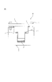
- FIG. 1 is a schematic cross-sectional view of a test jig used for an electrolytic solution leakage test.
- copolymers of the present disclosure contain tetrafluoroethylene (TFE) units and perfluoro (propyl vinyl ether) (PPVE) units.
- TFE tetrafluoroethylene
- PPVE perfluoro (propyl vinyl ether)
- Patent Document 1 an in-vehicle secondary battery is sometimes exposed to a high temperature of 85 ° C. or higher in a usage environment, and in order to maintain the airtightness and liquidtightness inside the battery, such severeness is obtained. It has been described that it is important that the sealing material maintains sufficient compressive restoration property even under various conditions of use and can maintain high adhesion between the battery can body and the sealing body.
- the glass transition temperature of the copolymer is sufficiently increased, which is excellent. It was found to show heat resistance. It has also been found that such a copolymer can be easily molded by an injection molding method, does not easily corrode the mold used for molding, and has excellent electrical characteristics. Further, the molded body having such a copolymer has excellent low water permeability, low permeability of the electrolytic solution, difficulty in leaking the electrolytic solution, crack resistance against compressive stress, heat deformation resistance and resistance to heat deformation. It was also found that it has excellent wear resistance, very good sealing performance at high temperature, and it is difficult to elute fluorine ions into the electrolytic solution.
- the copolymer of the present disclosure is a melt-processable fluororesin. Melt processability means that it is possible to melt and process a polymer using conventional processing equipment such as an extruder and an injection molding machine.
- the content of PVE units of the copolymer is 2.0 to 2.8% by mass with respect to all the monomer units.
- the content of the PVE unit of the copolymer is preferably 2.1% by mass or more, more preferably 2.2% by mass or more, still more preferably 2.3% by mass or more, and particularly preferably 2 It is 0.4% by mass or more, preferably 2.7% by mass or less.
- a copolymer having a higher glass transition temperature can be obtained, the water vapor permeability is very low, and the electrolytic solution low permeability is excellent. It is possible to obtain a copolymer that does not easily leak the electrolytic solution, has excellent crack resistance against compressive stress, heat-resistant deformation resistance, and abrasion resistance, and gives a molded body having extremely excellent sealing properties at high temperatures.
- the content of the TFE unit of the copolymer is preferably 97.2 to 98.0% by mass, more preferably 97.8% by mass or less, still more preferably 97, based on the total monomer unit. It is 7.7% by mass or less, more preferably 97.7% by mass or less, particularly preferably 97.6% by mass or less, and preferably 97.3% by mass or more.
- a copolymer having a higher glass transition temperature can be obtained, the water vapor permeability is very low, and the electrolytic solution low permeability is excellent. It is possible to obtain a copolymer that does not easily leak the electrolytic solution, has excellent crack resistance against compressive stress, heat-resistant deformation resistance, and abrasion resistance, and gives a molded body having extremely excellent sealing properties at high temperatures.
- the content of each monomer unit in the copolymer is measured by the 19 F-NMR method.
- the copolymer can also contain a monomer unit derived from a monomer copolymerizable with TFE and PPVE.
- the content of the monomer unit copolymerizable with TFE and PPVE is preferably 0 to 4.0% by mass, more preferably 0.% by mass, based on all the monomer units of the copolymer. It is 05 to 0.80% by mass, more preferably 0.1 to 0.5% by mass.
- HFP hexafluoropropylene
- Examples thereof include an alkyl perfluorovinyl ether derivative represented by 2 -Rf 1 (in the formula, Rf 1 represents a perfluoroalkyl group having 1 to 5 carbon atoms). Of these, HFP is preferable.
- the copolymer at least one selected from the group consisting of only TFE units and PPVE units and the group consisting of TFE / HFP / PPVE copolymers is preferable, and the copolymer consisting of only TFE units and PPVE units is preferable. Polymers are more preferred.
- the melt flow rate (MFR) of the copolymer is 5 to 23 g / 10 minutes.
- the MFR of the copolymer is preferably 6 g / 10 minutes or more, more preferably 7 g / 10 minutes or more, further preferably 8 g / 10 minutes or more, preferably 21 g / 10 minutes or less, and more. It is preferably 20 g / 10 minutes or less, more preferably 19 g / 10 minutes or less, particularly preferably 18 g / 10 minutes or less, and most preferably 16 g / 10 minutes or less.
- the MFR of the copolymer is within the above range, it can be easily molded by the injection molding method, has excellent low water permeability, excellent low permeability of the electrolytic solution, and hardly leaks the electrolytic solution.
- a copolymer that provides a molded product having excellent wear resistance and heat deformation resistance and extremely excellent sealing properties at high temperatures can be obtained.
- the MFR according to ASTM D1238, using a melt indexer, the mass of polymer (g / 10 min) flowing out from a nozzle with an inner diameter of 2.1 mm and a length of 8 mm under a load of 372 ° C and 5 kg per 10 minutes. ).
- the MFR can be adjusted by adjusting the type and amount of the polymerization initiator used when polymerizing the monomer, the type and amount of the chain transfer agent, and the like.
- the number of functional groups per 106 main chains of the copolymer is 50 or less.
- the number of functional groups per 10 to 6 main chains of the copolymer is preferably 40 or less, more preferably 30 or less, still more preferably 20 or less, still more preferably 15 or less. It is particularly preferably 10 or less, and most preferably less than 6.
- Infrared spectroscopy can be used to identify the type of functional group and measure the number of functional groups.
- the number of functional groups is measured by the following method.
- the above-mentioned copolymer is molded by cold pressing to prepare a film having a thickness of 0.25 to 0.30 mm.
- This film is analyzed by Fourier transform infrared spectroscopy to obtain an infrared absorption spectrum of the above-mentioned copolymer, and a difference spectrum from a base spectrum which is completely fluorinated and has no functional group is obtained. From the absorption peak of a specific functional group appearing in this difference spectrum, the number N of functional groups per 1 ⁇ 10 6 carbon atoms in the above-mentioned copolymer is calculated according to the following formula (A).
- N I ⁇ K / t (A) I: Absorbance K: Correction coefficient t: Film thickness (mm)
- the absorption frequency, molar absorption coefficient and correction coefficient for some functional groups are shown in Table 1.
- the molar extinction coefficient was determined from the FT-IR measurement data of the small molecule model compound.
- the number of functional groups of -COF is determined from the number of functional groups obtained from the absorption peak of absorption frequency 1883 cm -1 caused by -CF 2 COF and the absorption peak of absorption frequency 1840 cm -1 caused by -CH 2 COF. It is the total with the number of functional groups.
- the functional group is a functional group present at the end of the main chain or the end of the side chain of the copolymer, and a functional group present in the main chain or the side chain.
- the functional group is introduced into the copolymer by, for example, a chain transfer agent or a polymerization initiator used in producing the copolymer.
- a chain transfer agent or a polymerization initiator used in producing the copolymer.
- a chain transfer agent or a peroxide having a structure of -CH 2 OH is used as a polymerization initiator
- -CH 2 OH is introduced at the end of the main chain of the copolymer.
- the functional group is introduced into the side chain terminal of the copolymer.
- the copolymer of the present disclosure is preferably fluorinated.
- the copolymers of the present disclosure also preferably have a -CF 3 -terminal group.
- the melting point of the copolymer is preferably 305 to 317 ° C, more preferably 305 to 315 ° C. When the melting point is within the above range, it is possible to obtain a copolymer that gives a molded product having further excellent sealing properties particularly at high temperatures.
- the melting point can be measured using a differential scanning calorimeter [DSC].
- the glass transition temperature (Tg) of the copolymer is preferably 95 ° C. or higher, more preferably 98 ° C. or higher, more preferably 99 ° C. or higher, preferably 110 ° C. or lower, and more preferably 105 ° C. or higher. It is °C or less, and more preferably 103 °C or less. Since the copolymer of the present disclosure can have such a high glass transition temperature, it is possible to obtain a copolymer which exhibits excellent heat resistance and gives a molded product which is particularly excellent in sealing property at a high temperature. ..
- the glass transition temperature can be measured by dynamic viscoelasticity measurement.
- the water vapor permeability of the copolymer is preferably 8.5 g ⁇ cm / m 2 or less, more preferably 8.0 g ⁇ cm / m 2 or less, still more preferably 7.9 g ⁇ cm / m 2 or less. It is more preferably 7.6 g ⁇ cm / m 2 or less.
- the copolymers of the present disclosure are excellent in water vapor because the content of PVE units, melt flow rate (MFR) and number of functional groups of the copolymer containing TFE units and PPVE units are appropriately adjusted. Has low permeability. Therefore, by using the molded product containing the copolymer of the present disclosure as, for example, a member to be compressed of a secondary battery, it is possible to effectively prevent the permeation of water even under high temperature and high humidity conditions.
- the water vapor transmission rate can be measured under the conditions of a temperature of 95 ° C. and 30 days. Specific measurement of water vapor transmission rate can be performed by the method described in Examples.
- the electrolyte permeability of the copolymer is preferably 7.5 g ⁇ cm / m 2 or less, more preferably 7.3 g ⁇ cm / m 2 or less, and even more preferably 7.1 g ⁇ cm / m 2 . It is as follows.
- the copolymers of the present disclosure are very excellent in electrolysis because the content of PPVE units, melt flow rate (MFR) and number of functional groups of the copolymer containing TFE units and PPVE units are appropriately adjusted. Has low liquid permeability. Therefore, by using the molded body containing the copolymer of the present disclosure as, for example, a member to be compressed of the secondary battery, it is possible to effectively prevent the permeation of the electrolytic solution contained in the secondary battery.
- the specific measurement of the electrolyte permeability can be performed by the method described in the examples.
- the amount of eluted fluorine ions detected in the electrolytic solution immersion test is preferably 1.0 ppm or less, more preferably 0.8 ppm or less, still more preferably 0. It is 7 ppm or less.
- the amount of eluted fluorine ions is within the above range, the generation of gas such as HF in the non-aqueous electrolyte battery can be further suppressed, and the deterioration of the battery performance and the shortening of the battery life of the non-aqueous electrolyte battery can be further suppressed. can.
- a test piece having a weight corresponding to 10 molded bodies (15 mm ⁇ 15 mm ⁇ 0.2 mm) is prepared using a copolymer, and the test piece and 2 g of dimethyl carbonate (2 g) are prepared. This can be done by placing a glass sample bottle containing DMC) in a constant temperature bath at 80 ° C. and leaving it to stand for 144 hours.
- the copolymer of the present disclosure can provide a molded product having excellent sealing properties at high temperatures.
- the sealing property at high temperature can be evaluated by measuring the storage elastic modulus (E') at 150 ° C., the restoration amount at 150 ° C., and the surface pressure at 150 ° C.
- a copolymer having a high storage elastic modulus (E') at 150 ° C. and a large restoration amount at 150 ° C. enables sufficient rebound resilience to be continuously exhibited even at high temperatures for a long period of time.
- the copolymer having a high surface pressure at 150 ° C. can give a molded product having excellent sealing property at a high temperature.
- the copolymer of the present disclosure can provide a molded product having excellent sealing properties even at a high temperature exceeding the glass transition temperature of the copolymer.
- the storage elastic modulus (E') of the copolymer at 150 ° C. is preferably 140 MPa or more, more preferably 145 MPa or more, still more preferably 148 MPa or more, preferably 1000 MPa or less, and more preferably. It is 500 MPa or less, more preferably 300 MPa or less.
- the storage elastic modulus (E') of the copolymer at 150 ° C. is within the above range, sufficient impact resilience can be continuously exhibited even at high temperatures for a long period of time, and molding at high temperatures is even better. A copolymer that gives the body can be obtained.
- the storage elastic modulus (E') can be measured by performing dynamic viscoelasticity measurement in the range of 30 to 250 ° C. under the conditions of a heating rate of 2 ° C./min and a frequency of 10 Hz.
- the storage modulus (E') at 150 ° C. can be increased by adjusting the content of PPVE units of the copolymer and the melt flow rate (MFR).
- the surface pressure of the copolymer at 150 ° C. is preferably 1.60 MPa or more, more preferably 1.65 MPa or more, still more preferably 1.70 MPa or more, and the upper limit is not particularly limited, but 3.00 MPa. It may be as follows.
- the surface pressure at 150 ° C. can be increased by adjusting the content of the copolymer in PPVE units, the melt flow rate (MFR) and the number of functional groups.
- the surface pressure was adjusted by leaving the test piece obtained from the copolymer deformed at a compression deformation rate of 50% at 150 ° C. for 18 hours, releasing the compressed state, leaving it at room temperature for 30 minutes, and then the test piece. (The height of the test piece after compression deformation) is measured, and it is calculated by the following formula from the height of the test piece after compression deformation and the storage elastic modulus (MPa) at 150 ° C. Can be done. 150 ° C.
- the amount of the copolymer restored at 150 ° C. can be measured by the same method as the measurement of the surface pressure.
- the amount of restoration of the molded product at 150 ° C. is the height (t 2 ) of the test piece after compression deformation and the test piece before compression deformation when the test piece is deformed at a compression deformation rate of 50%. It is the difference (t 2 -t 1 ) from the original height (t 1 ) of.
- the amount of restoration of the molded product at 150 ° C. can be increased by adjusting the content of the copolymer in PPVE units, the melt flow rate (MFR) and the number of functional groups.
- the dielectric loss tangent of the copolymers of the present disclosure at 6 GHz is preferably 6.0 ⁇ 10 -4 or less, more preferably 5.0 ⁇ 10 -4 or less, and even more preferably 4.0 ⁇ 10 -4 . It is as follows. In recent years, as the amount of information transmitted has increased, radio waves in the high frequency region have tended to be used more and more. For example, microwaves of 3 to 30 GHz are used for high-frequency wireless LAN, satellite communication, mobile phone base stations, and the like. As a material of a material used for a communication device using such a high frequency, a material having a low dielectric loss tangent (tan ⁇ ) is required. When the dielectric loss tangent of the copolymer of the present disclosure is in the above range, the attenuation rate of the high frequency signal is greatly reduced, which is preferable.
- the dielectric loss tangent is a value obtained by measuring changes in resonance frequency and electric field strength in a temperature range of 20 to 25 ° C. using a network analyzer manufactured by Agilent Technologies and a cavity resonator.
- the copolymer of the present disclosure can be produced by a polymerization method such as suspension polymerization, solution polymerization, emulsion polymerization, bulk polymerization and the like. Emulsion polymerization or suspension polymerization is preferable as the polymerization method.
- a polymerization method such as suspension polymerization, solution polymerization, emulsion polymerization, bulk polymerization and the like.
- Emulsion polymerization or suspension polymerization is preferable as the polymerization method.
- each condition such as temperature and pressure, the polymerization initiator and other additives can be appropriately set according to the composition and amount of the copolymer.
- an oil-soluble radical polymerization initiator or a water-soluble radical polymerization initiator can be used as the polymerization initiator.
- the oil-soluble radical polymerization initiator may be a known oil-soluble peroxide, for example, Dialkyl peroxy carbonates such as dinormal propyl peroxy dicarbonate, diisopropyl peroxy dicarbonate, disec-butyl peroxy dicarbonate, di-2-ethoxyethyl peroxy dicarbonate; Peroxyesters such as t-butylperoxyisobutyrate, t-butylperoxypivalate; Dialkyl peroxides such as dit-butyl peroxide; Di [fluoro (or fluorochloro) acyl] peroxides; Etc. are typical examples.
- Dialkyl peroxy carbonates such as dinormal propyl peroxy dicarbonate, diisopropyl peroxy dicarbonate, disec-butyl peroxy dicarbonate, di-2-ethoxyethyl peroxy dicarbonate
- Peroxyesters such as t-butylperoxyisobutyrate, t-
- Di [fluoro (or fluorochloro) acyl] peroxides are represented by [(RfCOO)-] 2 (Rf is a perfluoroalkyl group, ⁇ -hydroperfluoroalkyl group or fluorochloroalkyl group). Peroxide can be mentioned.
- di [fluoro (or fluorochloro) acyl] peroxides examples include di ( ⁇ -hydro-dodecafluorohexanoyl) peroxide, di ( ⁇ -hydro-tetradecafluoroheptanoid) peroxide, and di ( ⁇ ).
- the water-soluble radical polymerization initiator may be a known water-soluble peroxide, for example, ammonium salts such as persulfuric acid, perboric acid, perchloric acid, perphosphoric acid, and percarbonate, potassium salt, sodium salt, and dicohaku. Examples thereof include organic peroxides such as acid peroxide and diglutaric acid peroxide, t-butyl permalate, and t-butyl hydroperoxide. A reducing agent such as sulfite may be used in combination with the peroxide, and the amount used may be 0.1 to 20 times that of the peroxide.
- ammonium salts such as persulfuric acid, perboric acid, perchloric acid, perphosphoric acid, and percarbonate, potassium salt, sodium salt, and dicohaku. Examples thereof include organic peroxides such as acid peroxide and diglutaric acid peroxide, t-butyl permalate, and t-butyl hydroperoxide.
- a surfactant In the polymerization, a surfactant, a chain transfer agent, and a solvent can be used, and conventionally known ones can be used for each.
- a known surfactant can be used, and for example, a nonionic surfactant, an anionic surfactant, a cationic surfactant, or the like can be used.
- a fluorine-containing anionic surfactant is preferable, and it may contain ether-bonding oxygen (that is, oxygen atoms may be inserted between carbon atoms), and it may be linear or branched with 4 to 20 carbon atoms. Fluorine-containing anionic surfactants are more preferred.
- the amount of the surfactant added is preferably 50 to 5000 ppm.
- chain transfer agent examples include hydrocarbons such as ethane, isopentan, n-hexane and cyclohexane; aromatics such as toluene and xylene; ketones such as acetone; acetates such as ethyl acetate and butyl acetate; methanol. , Alcohols such as ethanol; mercaptans such as methyl mercaptan; halogenated hydrocarbons such as carbon tetrachloride, chloroform, methylene chloride, methyl chloride and the like.
- the amount of the chain transfer agent added may vary depending on the magnitude of the chain transfer constant of the compound used, but is usually used in the range of 0.01 to 20% by mass with respect to the polymerization solvent.
- Examples of the solvent include water and a mixed solvent of water and alcohol.
- a fluorine-based solvent may be used in addition to water.
- Fluorine-based solvents include hydrochloroalkanes such as CH 3 CClF 2 , CH 3 CCl 2 F, CF 3 CF 2 CCl 2 H, CF 2 ClCF 2 CF HCl; CF 2 ClCFClCF 2 CF 3 , CF 3 CFClCFClCF 3 , etc.
- Chlorofluoroalkanes CF 3 CFHCFHCF 2 CF 2 CF 3 , CF 2 HCF 2 CF 2 CF 2 H, CF 3 CF 2 CF 2 CF 2 CF 2 H and other hydrofluoroalkanes; CH 3 OC 2 F 5 , CH 3 OC 3 F 5 CF 3 CF 2 CH 2 OCHF 2 , CF 3 CHFCF 2 OCH 3 , CHF 2 CF 2 OCH 2 F, (CF 3 ) 2 CHCF 2 OCH 3 , CF 3 CF 2 Hydrofluoroethers such as CH 2 OCH 2 CHF 2 , CF 3 CHFCF 2 OCH 2 CF 3 ; perfluorocyclobutane, CF 3 CF 2 CF 2 CF 3 , CF 3 CF 2 CF 2 CF 2 CF 3 , CF 3 CF 2 Examples thereof include perfluoroalkanes such as CF 2 CF 2 CF 2 CF 2 ,
- the polymerization temperature is not particularly limited and may be 0 to 100 ° C.
- the polymerization pressure is appropriately determined depending on the type and amount of the solvent used and other polymerization conditions such as vapor pressure and polymerization temperature, but is usually 0 to 9.8 MPaG.
- the copolymer When an aqueous dispersion containing the copolymer is obtained by the polymerization reaction, the copolymer can be recovered by coagulating, washing and drying the copolymer contained in the aqueous dispersion.
- the copolymer When the copolymer is obtained as a slurry by the polymerization reaction, the copolymer can be recovered by taking out the slurry from the reaction vessel, washing the slurry, and drying the slurry. By drying, the copolymer can be recovered in the form of powder.
- the copolymer obtained by polymerization may be molded into pellets.
- the molding method for molding into pellets is not particularly limited, and a conventionally known method can be used. For example, a method of melt-extruding a copolymer using a single-screw extruder, a twin-screw extruder, or a tandem extruder, cutting the copolymer to a predetermined length, and forming the copolymer into pellets can be mentioned.
- the extrusion temperature at the time of melt extrusion needs to be changed depending on the melt viscosity of the copolymer and the production method, and is preferably the melting point of the copolymer + 20 ° C. to the melting point of the copolymer + 140 ° C.
- the method for cutting the copolymer is not particularly limited, and conventionally known methods such as a strand cut method, a hot cut method, an underwater cut method, and a sheet cut method can be adopted.
- the obtained pellets may be heated to remove volatile components in the pellets (deaeration treatment).
- the obtained pellets may be treated by contacting them with warm water at 30 to 200 ° C., steam at 100 to 200 ° C., or warm air at 40 to 200 ° C.
- the copolymer obtained by the polymerization may be fluorinated.
- the fluorination treatment can be carried out by contacting the non-fluorinated copolymer with the fluorine-containing compound.
- Functional groups such as the stable -CF 2 H can be converted to the thermally extremely stable -CF 3 .
- the fluorine-containing compound is not particularly limited, and examples thereof include a fluorine radical source that generates fluorine radicals under fluorination treatment conditions.
- a fluorine radical source that generates fluorine radicals under fluorination treatment conditions.
- the fluorine radical source include F 2 gas, CoF 3 , AgF 2 , UF 6 , OF 2 , N 2 F 2 , CF 3 OF, and halogen fluoride (for example, IF 5 , ClF 3 ).
- the fluorine radical source such as F 2 gas may have a concentration of 100%, but from the viewpoint of safety, it is preferably mixed with an inert gas and diluted to 5 to 50% by mass before use. It is more preferable to dilute it to about 30% by mass before use.
- inert gas examples include nitrogen gas, helium gas, argon gas and the like, but nitrogen gas is preferable from the economical point of view.
- the conditions of the fluorination treatment are not particularly limited, and the melted copolymer may be brought into contact with the fluorine-containing compound, but usually, it is usually below the melting point of the copolymer, preferably 20 to 240 ° C. It can be preferably carried out at a temperature of 100 to 220 ° C.
- the fluorination treatment is generally carried out for 1 to 30 hours, preferably 5 to 25 hours.
- the fluorination treatment is preferably such that the non-fluorinated copolymer is brought into contact with a fluorine gas (F 2 gas).
- the copolymer of the present disclosure may be mixed with other components, if necessary, to obtain a composition.
- Other components include fillers, plasticizers, processing aids, mold release agents, pigments, flame retardants, lubricants, light stabilizers, weather stabilizers, conductive agents, antistatic agents, UV absorbers, antioxidants, etc. Examples thereof include foaming agents, fragrances, oils, softening agents, defluorinated hydrogenating agents and the like.
- Fillers include, for example, silica, kaolin, clay, organic clay, talc, mica, alumina, calcium carbonate, calcium terephthalate, titanium oxide, calcium phosphate, calcium fluoride, lithium fluoride, crosslinked polystyrene, potassium titanate, etc. Examples thereof include carbon, boron fluoride, carbon nanotubes, and glass fiber.
- Examples of the conductive agent include carbon black and the like.
- Examples of the plasticizer include dioctylphthalic acid and pentaerythritol.
- the processing aid include carnauba wax, a sulfone compound, low molecular weight polyethylene, a fluorine-based auxiliary agent, and the like.
- the defluorinated hydrogenating agent include organic onium and amidines.
- polymers other than the above-mentioned copolymer may be used.
- examples of other polymers include fluororesins other than the above-mentioned copolymers, fluororubbers, non-fluorinated polymers and the like.
- a method for producing the above composition a method of mixing the copolymer and other components in a dry manner, or a method of mixing the copolymer and other components in advance with a mixer, and then using a kneader, a melt extruder, or the like. Examples thereof include a method of melt-kneading.
- the copolymer of the present disclosure or the above composition can be used as a processing aid, a molding material, etc., it is preferable to use it as a molding material.
- Aqueous dispersions, solutions, suspensions, and copolymer / solvent systems of the copolymers of the present disclosure are also available, which can be applied as paints, used for encapsulation, impregnation, and film casting. Can be done.
- the copolymer of the present disclosure has the above-mentioned properties, it is preferable to use it as the above-mentioned molding material.
- copolymer of the present disclosure or the above composition may be molded to obtain a molded product.
- the method for molding the copolymer or the composition is not particularly limited, and examples thereof include an injection molding method, an extrusion molding method, a compression molding method, a blow molding method, a transfer molding method, a roto molding method, and a lotining molding method. ..
- the molding method the extrusion molding method, the compression molding method, the injection molding method or the transfer molding method is preferable, and since the molded product can be produced with high productivity, the injection molding method, the extrusion molding method or the transfer molding method is more preferable.
- an injection molding method is more preferred.
- the molded body is preferably an extrusion molded body, a compression molded body, an injection molded body or a transfer molded body, and is an injection molded body, an injection molded body or a transfer molded body because it can be produced with high productivity. Is more preferable, and it is further preferable that it is an injection molded product.
- the shape of the molded body is not particularly limited, and may be, for example, a hose, a pipe, a tube, an electric wire coating, a sheet, a seal, a gasket, a packing, a film, a tank, a roller, a bottle, a container, or the like.
- the copolymer, the above composition, or the above molded article of the present disclosure can be used, for example, in the following applications.
- Fluid transfer materials for food manufacturing equipment such as food packaging films, lining materials for fluid transfer lines used in the food manufacturing process, packings, sealing materials, sheets, etc.
- Chemical transfer members such as chemical plugs, packaging films, lining materials for fluid transfer lines used in the chemical manufacturing process, packings, sealing materials, sheets, etc.
- Internal lining members for chemical tanks and pipes in chemical plants and semiconductor factories O (corner) ring, tube, packing, valve core material, hose, sealing material, etc. used for automobile fuel system and peripheral devices, hose, sealing material, etc.
- examples of the fuel transfer member used in the fuel system of the automobile include a fuel hose, a filler hose, an evaporative hose, and the like.
- the fuel transfer member can also be used as a fuel transfer member for sour-resistant gasoline, alcohol-resistant fuel, and fuel containing gasoline additives such as methyltaltal butyl ether and amine-resistant.
- the drug stopper / packaging film for the above chemicals has excellent chemical resistance against acids and the like. Further, as the chemical liquid transfer member, an anticorrosion tape wrapped around a chemical plant pipe can be mentioned.
- Examples of the molded product include radiator tanks for automobiles, chemical tanks, bellows, spacers, rollers, gasoline tanks, waste liquid transport containers, high temperature liquid transport containers, fishery / fish farming tanks, and the like.
- the molded body further includes automobile bumpers, door trims, instrument panels, food processing equipment, cooking equipment, water- and oil-repellent glass, lighting-related equipment, display boards / housings for OA equipment, illuminated signs, displays, and liquid crystal. Also included are members used in displays, mobile phones, printed boards, electrical and electronic parts, miscellaneous goods, trash cans, bathtubs, unit baths, ventilation fans, lighting frames, and the like.
- the molded product containing the copolymer of the present disclosure has excellent heat resistance, can be easily manufactured by an injection molding method without corroding the mold, and has excellent low water permeability. Excellent low permeability of the electrolytic solution, difficult to leak the electrolytic solution, excellent crack resistance against compressive stress, heat resistance deformation resistance and wear resistance, excellent sealing property at high temperature, and fluorine ions in the electrolytic solution. Can be suitably used as a member to be compressed containing a copolymer because it is difficult to elute.
- the compressed member of the present disclosure exhibits a high surface pressure even when deformed at a high compression deformation rate.
- the member to be compressed of the present disclosure can be used in a state of being compressed and deformed with a compression deformation rate of 10% or more, and can be used in a state of being compressed and deformed with a compression deformation rate of 20% or more or 25% or more.
- the member to be compressed of the present disclosure exhibits a high storage elastic modulus, a high restoration amount, and a high surface pressure even when deformed at a high temperature and a high compression deformation rate.
- the member to be compressed of the present disclosure can be used in a state of being compression-deformed at a compression deformation rate of 10% or more at 150 ° C. or higher, and at a compression deformation rate of 20% or more or 25% or more at 150 ° C. or higher. It can be used in a compressed state.
- the above compression deformation rate is the compression deformation rate of the portion having the largest compression deformation rate when the member to be compressed is used in a compressed state.
- a flat member to be compressed is used in a state of being compressed in the thickness direction, it is the compression deformation rate in the thickness direction.
- the compression deformation rate of the portion having the largest compression deformation rate among the compression deformation rates of the compressed portions is the compression deformation rate of the portion having the largest compression deformation rate among the compression deformation rates of the compressed portions.
- the size and shape of the compressed member of the present disclosure may be appropriately set according to the intended use, and are not particularly limited.
- the shape of the compressed member of the present disclosure may be, for example, an annular shape.
- the member to be compressed of the present disclosure may have a shape such as a circle, an oval shape, or a quadrangle with rounded corners in a plan view, and may have a through hole at the center thereof.
- the compressed member of the present disclosure is preferably used as a member for constituting a non-aqueous electrolyte battery.
- the member to be compressed of the present disclosure is extremely excellent in low water permeability, excellent in low permeability of electrolytic solution, difficult to leak electrolytic solution, and excellent in crack resistance against compressive stress, heat deformation resistance and abrasion resistance. It is particularly suitable as a member used in contact with the non-aqueous electrolytic solution in a non-aqueous electrolytic solution battery because it has excellent sealing properties at high temperatures and it is difficult to elute fluorine ions into the electrolytic solution. Is. That is, the member to be compressed of the present disclosure may have a liquid contact surface with the non-aqueous electrolytic solution in the non-aqueous electrolytic solution battery.
- the compressed member of the present disclosure does not easily elute fluorine ions into the non-aqueous electrolytic solution. Therefore, by using the member to be compressed of the present disclosure, it is possible to suppress an increase in the fluorine ion concentration in the non-aqueous electrolytic solution. As a result, by using the member to be compressed of the present disclosure, it is possible to suppress the generation of gas such as HF in the non-aqueous electrolyte battery, and it is possible to suppress the deterioration of the battery performance and the shortening of the battery life of the non-aqueous electrolyte battery. Or something.
- the members to be compressed of the present disclosure can further suppress the generation of gas such as HF in the non-aqueous electrolyte battery, and can further suppress the deterioration of the battery performance and the shortening of the life of the non-aqueous electrolyte battery.
- the amount of eluted fluorine ions detected in the electrolytic solution immersion test is preferably 1.0 ppm or less, preferably 0.8 ppm or less, and more preferably 0.7 ppm or less on a mass basis.
- a test piece having a weight equivalent to 10 molded bodies (15 mm ⁇ 15 mm ⁇ 0.2 mm) is prepared using a member to be compressed, and the test piece and 2 g of dimethyl carbonate (DMC) are mixed. This can be done by placing the glass sample bottle in a constant temperature bath at 80 ° C. and leaving it to stand for 144 hours.
- DMC dimethyl carbonate
- the compressed member of the present disclosure is excellent in liquidtightness and low permeability of the electrolytic solution, and it is difficult for the electrolytic solution to leak or permeate. Therefore, by using the compressed member of the present disclosure, it is possible to suppress poor battery performance and shortened life of the non-aqueous electrolyte battery.
- the amount of electrolytic solution leaked from the member to be compressed of the present disclosure is preferably 0.0030 g / 1000 hrs or less, more preferably 0.0025 g /, because it can further suppress poor battery performance and shortened life of the non-aqueous electrolytic solution battery. It is 1000 hrs or less.
- the amount of electrolytic solution leaked from the member to be compressed can be measured by the method described in Examples.
- the compressed member of the present disclosure is difficult to allow water vapor to permeate. Therefore, by using the compressed member of the present disclosure, it is possible to suppress the permeation of water vapor from the outside into the secondary battery. As a result, by using the compressed member of the present disclosure, deterioration of battery performance and shortening of life of the non-aqueous electrolyte battery can be suppressed.
- the water vapor permeability of the member to be compressed of the present disclosure is preferably 8.5 g ⁇ cm / m 2 or less, more preferably 8 because the deterioration of the battery performance and the shortening of the life of the non-aqueous electrolyte battery can be further suppressed. It is 0.0 g ⁇ cm / m 2 or less, more preferably 7.9 g ⁇ cm / m 2 or less, and even more preferably 7.6 g ⁇ cm / m 2 or less.
- the water vapor transmission rate of the member to be compressed can be measured under the conditions of a temperature of 95 ° C. and 30 days.
- the non-aqueous electrolyte battery is not particularly limited as long as it is a battery including a non-aqueous electrolyte, and examples thereof include a lithium ion secondary battery and a lithium ion capacitor. Further, examples of the member constituting the non-aqueous electrolyte battery include a sealing member, an insulating member, and the like.
- the non-aqueous electrolyte solution is not particularly limited, but is propylene carbonate, ethylene carbonate, butylene carbonate, ⁇ -butyl lactone, 1,2-dimethoxyethane, 1,2-diethoxyethane, dimethyl carbonate, diethyl carbonate. , One or more of known solvents such as ethylmethyl carbonate can be used.
- the non-aqueous electrolyte battery may further include an electrolyte.
- the electrolyte is not particularly limited, but LiClO 4 , LiAsF 6 , LiPF 6 , LiBF 4 , LiCl, LiBr, CH 3 SO 3 Li, CF 3 SO 3 Li, cesium carbonate and the like can be used.
- the compressed member of the present disclosure can be suitably used as, for example, a sealing member such as a sealing gasket and a sealing packing, and an insulating member such as an insulating gasket and an insulating packing.
- the sealing member is a member used to prevent leakage of liquid or gas or intrusion of liquid or gas from the outside.
- the insulating member is a member used to insulate electricity.
- the members to be compressed of the present disclosure may be members used for both sealing and insulating purposes.
- the member to be compressed of the present disclosure is excellent in heat resistance and heat resistance deformation, and is also very excellent in sealing property at high temperature, so that it can be suitably used in an environment of high temperature.
- the compressed member of the present disclosure is preferably used in an environment where the maximum temperature is 40 ° C. or higher.
- the compressed member of the present disclosure is preferably used in an environment where the maximum temperature is 150 ° C. or higher.
- Examples of cases where the compressed member of the present disclosure can reach such a high temperature include, for example, a case where the compressed member is attached to the battery in a compressed state and then another battery member is attached to the battery by welding, or non-hydrolysis. For example, when the liquid battery generates heat.
- the member to be compressed of the present disclosure is extremely excellent in low water permeability, excellent in low permeability of electrolytic solution, difficult to leak electrolytic solution, and excellent in crack resistance against compressive stress, heat deformation resistance and abrasion resistance. It has excellent sealing properties at high temperatures and does not easily elute fluorine ions into the electrolytic solution. Therefore, it is suitably used as a sealing member for non-aqueous electrolytic solution batteries or an insulating member for non-aqueous electrolytic solution batteries. can.
- the temperature of the battery may be temporarily 40 ° C. or higher, particularly 150 ° C. or higher temporarily.
- the member to be compressed of the present disclosure may be used by being deformed at a high compression deformation rate at a high temperature in a battery such as a non-aqueous electrolyte secondary battery, or may be in contact with the non-aqueous electrolyte at a high temperature. , High impact resilience is not impaired. Therefore, when the compressed member of the present disclosure is used as a sealing member, it has excellent sealing characteristics and the sealing characteristics are maintained for a long period of time even under high temperature. Further, since the member to be compressed of the present disclosure contains the above-mentioned copolymer, it has excellent insulating properties. Therefore, when the compressed member of the present disclosure is used as an insulating member, it firmly adheres to two or more conductive members to prevent a short circuit for a long period of time.
- the copolymer of the present disclosure has a low dielectric loss tangent at 6 GHz, it can be suitably used as a material for products for high-frequency signal transmission.
- the high-frequency signal transmission product is not particularly limited as long as it is a product used for high-frequency signal transmission, and is (1) an insulating plate for a high-frequency circuit, an insulator for connecting parts, a molded plate such as a printed wiring board, and (2). Examples thereof include a base of a high-frequency vacuum tube, a molded body such as an antenna cover, and (3) a coated electric wire such as a coaxial cable and a LAN cable.
- the above-mentioned high-frequency signal transmission product can be suitably used for equipment using microwaves such as satellite communication equipment and mobile phone base stations, particularly microwaves of 3 to 30 GHz.
- the copolymer of the present disclosure can be suitably used as an insulator because of its low dielectric loss tangent.
- a printed wiring board is preferable in that good electrical characteristics can be obtained.
- the printed wiring board is not particularly limited, and examples thereof include printed wiring boards for electronic circuits of mobile phones, various computers, communication devices, and the like.
- an antenna cover is preferable because it has a low dielectric loss.
- a coated electric wire provided with a coating layer containing the copolymer of the present disclosure is preferable. That is, the molded product containing the copolymer of the present disclosure can be suitably used as a coating layer containing the copolymer.
- tetrafluoroethylene / fluoro (alkyl vinyl ether) copolymers are known to have a continuous use temperature of 260 ° C.
- the continuous operating temperature means the maximum operating temperature at which the polymer can continuously withstand.
- copolymers that can be used in more harsh working environments, in other words, have a continuous use temperature of over 260 ° C.
- Molds containing the copolymers of the present disclosure make it possible to have a continuous use temperature of 280 ° C.
- the molded product containing the copolymer of the present disclosure does not melt even at an extremely high temperature of 280 ° C., and the coating layer made of the molded product maintains the coating without forming bursts or cracks due to heat load and is continuous. Can be used as a target. Therefore, the molded product containing the copolymer of the present disclosure is suitable for use as a coating layer provided in a coated electric wire used in an environment where the maximum temperature is 280 ° C. or higher.
- the coated electric wire includes a core wire and a coating layer provided around the core wire and containing the copolymer of the present disclosure.
- a coating layer provided around the core wire and containing the copolymer of the present disclosure.
- an extruded body obtained by melt-extruding the copolymer of the present disclosure on a core wire can be used as the coating layer.
- the coated electric wire is suitable for high-frequency transmission cables, flat cables, heat-resistant cables and the like because the coating layer has excellent heat resistance and low dielectric loss tangent, and is particularly suitable for high-frequency transmission cables.
- the core wire for example, a metal conductor material such as copper or aluminum can be used.
- the core wire preferably has a diameter of 0.02 to 3 mm.
- the diameter of the core wire is more preferably 0.04 mm or more, further preferably 0.05 mm or more, and particularly preferably 0.1 mm or more.
- the diameter of the core wire is more preferably 2 mm or less.
- the core wire include, for example, AWG (American Wire Gauge) -46 (solid copper wire with a diameter of 40 micrometer), AWG-26 (solid copper wire with a diameter of 404 micrometer), and AWG-24 (diameter). 510 micrometer solid copper wire), AWG-22 (635 micrometer diameter solid copper wire) and the like may be used.
- AWG American Wire Gauge
- -46 solid copper wire with a diameter of 40 micrometer
- AWG-26 solid copper wire with a diameter of 404 micrometer
- AWG-24 diameter
- AWG-22 (635 micrometer diameter solid copper wire) and the like may be used.
- the thickness of the coating layer is preferably 0.1 to 3.0 mm.
- the thickness of the coating layer is also preferably 2.0 mm or less.
- a coaxial cable can be mentioned as a high frequency transmission cable.
- a coaxial cable generally has a structure in which an inner conductor, an insulating coating layer, an outer conductor layer, and a protective coating layer are sequentially laminated from a core portion to an outer peripheral portion.
- the molded product containing the copolymer of the present disclosure can be suitably used as an insulating coating layer containing the copolymer.
- the thickness of each layer in the above structure is not particularly limited, but usually, the inner conductor has a diameter of about 0.1 to 3 mm, the insulating coating layer has a thickness of about 0.3 to 3 mm, and the outer conductor layer has a thickness of about about 0.3 to 3 mm.
- the protective coating layer is 0.5 to 10 mm and the thickness is about 0.5 to 2 mm.
- the coating layer may contain air bubbles, and it is preferable that the air bubbles are uniformly distributed in the coating layer.
- the average bubble diameter of the bubbles is not limited, but is preferably 60 ⁇ m or less, more preferably 45 ⁇ m or less, further preferably 35 ⁇ m or less, still more preferably 30 ⁇ m or less. It is particularly preferably 25 ⁇ m or less, and even more preferably 23 ⁇ m or less.
- the average bubble diameter is preferably 0.1 ⁇ m or more, and more preferably 1 ⁇ m or more.
- the average bubble diameter can be obtained by taking an electron microscope image of the cross section of the electric wire, calculating the diameter of each bubble by image processing, and averaging them.
- the coating layer may have a foaming rate of 20% or more. It is more preferably 30% or more, further preferably 33% or more, and even more preferably 35% or more.
- the upper limit is not particularly limited, but is, for example, 80%.
- the upper limit of the foaming rate may be 60%.
- the foaming ratio is a value obtained as ((specific gravity of the electric wire coating material-specific gravity of the coating layer) / specific gravity of the electric wire coating material) ⁇ 100.
- the foaming rate can be appropriately adjusted according to the application, for example, by adjusting the amount of gas inserted in the extruder, which will be described later, or by selecting the type of gas to be dissolved.
- the coated electric wire may be provided with another layer between the core wire and the coating layer, or may be further provided with another layer (outer layer) around the coating layer.
- the electric wire of the present disclosure has a two-layer structure (skin-foam) in which a non-foaming layer is inserted between the core wire and the coating layer, or a two-layer structure in which the outer layer is coated with the non-foaming layer. (Foam-skin), and further, a three-layer structure (skin-foam-skin) in which a non-foaming layer is coated on the outer layer of the skin-foam may be used.
- the non-foaming layer is not particularly limited, and is a TFE / HFP-based copolymer, a TFE / PAVE copolymer, a TFE / ethylene-based copolymer, a vinylidene fluoride-based polymer, a polyolefin resin such as polyethylene [PE], and polychloride. It may be a resin layer made of a resin such as vinyl [PVC].
- the coated electric wire can be manufactured, for example, by heating the copolymer using an extruder and extruding the copolymer in a molten state onto the core wire to form a coated layer.
- the coating layer containing bubbles can be formed by heating the copolymer and introducing a gas into the copolymer in a state where the copolymer is melted.
- a gas such as chlorodifluoromethane, nitrogen, carbon dioxide or a mixture of the above gases can be used.
- the gas may be introduced as a pressurized gas into the heated copolymer, or may be generated by mixing a chemical foaming agent into the copolymer. The gas dissolves in the melted copolymer.
- the molded product containing the copolymer of the present disclosure is excellent in heat resistance, it can be suitably used as a film containing the copolymer.
- a copolymer of tetrafluoroethylene and fluoro (alkyl vinyl ether) has excellent chemical resistance and heat resistance, and can be melt-molded, so it is useful as a surface material for mold release films and rolls used in OA equipment. be.
- high heat resistance that can withstand heat laminating processing has been required, and in the field of OA equipment, colorization and speeding up have progressed, and the surface material of the roll of the fixing part also has higher heat resistance. Is being sought after, and the severe situation continues.
- the copolymer of the present disclosure is formed from the copolymer because the content of the PVE unit and the melt flow rate (MFR) of the copolymer containing the TFE unit and the PPVE unit are appropriately adjusted.
- the film has high heat resistance. In the above-mentioned thermal laminating process, it is required to be able to withstand a wide temperature condition of about 100 to 300 ° C., but since the copolymer of the present disclosure has the above-mentioned structure, it is suitable even under harsh temperature conditions. Can be used.
- the copolymer-containing film of the present disclosure does not melt even at an extremely high temperature of 280 ° C., and due to its high glass transition temperature, it can withstand softening up to nearly 100 ° C. Therefore, the film containing the copolymer of the present disclosure is suitable for use as a heat-resistant film used in an environment where the maximum temperature is 280 ° C. or higher.
- the release film can be produced by molding the copolymer of the present disclosure by melt extrusion molding, calender molding, press molding, cast molding or the like. From the viewpoint of obtaining a uniform thin film, a release film can be produced by melt extrusion molding.
- the copolymer of the present disclosure is formed into a required shape by extrusion molding, compression molding, press molding, etc. to form a sheet, a film, or a tube, and is used as a surface material such as an OA equipment roll or an OA equipment belt. can do.
- thin-walled tubes and films can be manufactured by the melt extrusion molding method.
- the content of each monomer unit was measured by an NMR analyzer (for example, AVANCE 300 high temperature probe manufactured by Bruker Biospin).
- MFR Melt flow rate
- N I ⁇ K / t (A)
- K Correction coefficient
- t Film thickness (mm)
- Table 2 shows the absorption frequency, the molar absorption coefficient, and the correction coefficient for the functional groups in the present disclosure.
- the molar extinction coefficient is determined from the FT-IR measurement data of the small molecule model compound.
- Glass transition temperature (Tg) Glass transition temperature (Tg)
- DVA-220 manufactured by IT Measurement Control Co., Ltd.
- the temperature was measured at a heating rate of 2 ° C./min and a frequency of 10 Hz, and the temperature at the peak of the tan ⁇ value was determined as the glass transition temperature.
- Example 1 53.8 L of pure water was put into an autoclave having a volume of 174 L, and after sufficient nitrogen substitution, 41.7 kg of perfluorocyclobutane, 0.44 kg of perfluoro (propyl vinyl ether) (PPVE), and 0.61 kg of methanol were charged. The temperature in the system was maintained at 35 ° C. and the stirring speed was maintained at 200 rpm. Then, after press-fitting tetrafluoroethylene (TFE) to 0.5 MPa, 0.224 kg of a 50% methanol solution of di-n-propylperoxydicarbonate was added to initiate polymerization.
- TFE tetrafluoroethylene
- the obtained powder was melt-extruded at 360 ° C. using a screw extruder (trade name: PCM46, manufactured by Ikegai Corp.) to obtain pellets of a TFE / PPV copolymer.
- the PPVE content was measured using the obtained pellets by the above method. The results are shown in Table 3.
- the obtained pellets were placed in a vacuum vibration type reactor VVD-30 (manufactured by Okawara Seisakusho) and heated to 210 ° C. After evacuation, F 2 gas diluted to 20% by volume with N 2 gas was introduced to atmospheric pressure. 0.5 hours after the introduction of the F 2 gas, the vacuum was once evacuated and the F 2 gas was introduced again. Further 0.5 hours later, the vacuum was evacuated again and F 2 gas was introduced again. After that, the above F 2 gas introduction and evacuation operations were continued once an hour, and the reaction was carried out at a temperature of 210 ° C. for 10 hours. After completion of the reaction, the inside of the reactor was sufficiently replaced with N2 gas to complete the fluorination reaction. Various physical properties were measured by the above-mentioned method using fluorinated pellets. The results are shown in Table 3.
- Example 2 Fluorinated pellets were obtained in the same manner as in Example 1 except that PPVE was changed to 0.49 kg, methanol was 0.96 kg, and PPVE was changed to 0.025 kg for every 1 kg of TFE supplied. The results are shown in Table 3.
- Example 3 Fluorinated pellets in the same manner as in Example 1 except that 0.53 kg of PPVE, 0.42 kg of methanol, 0.027 kg of PPVE were added for each 1 kg of TFE supplied, and the polymerization time was changed to 7.5 hours. Got The results are shown in Table 3.
- Example 4 Add 0.53 kg of PPVE, 1.04 kg of methanol, 0.027 kg of PPVE for every 1 kg of TFE supplied, polymerization time is 7.5 hours, temperature rise of vacuum vibration reactor is 180 ° C, reaction is 180 ° C. Fluorinated pellets were obtained in the same manner as in Example 1 except that the temperature was changed to 10 hours. The results are shown in Table 3.
- Example 5 Add 0.53 kg of PPVE, 1.29 kg of methanol, 0.027 kg of PPVE for every 1 kg of TFE supplied, polymerization time is 7.5 hours, temperature rise of vacuum vibration reactor is 180 ° C, reaction is 180 ° C. Fluorinated pellets were obtained in the same manner as in Example 1 except that the temperature was changed to 10 hours. The results are shown in Table 3.
- Example 6 Fluorinated pellets in the same manner as in Example 1 except that 0.55 kg of PPVE, 0.71 kg of methanol, 0.028 kg of PPVE were added for each 1 kg of TFE supplied, and the polymerization time was changed to 7.5 hours. Got The results are shown in Table 3.
- Example 7 Fluorinated pellets in the same manner as in Example 1 except that 0.55 kg of PPVE, 1.16 kg of methanol, 0.028 kg of PPVE were added for each 1 kg of TFE supplied, and the polymerization time was changed to 7.5 hours. Got The results are shown in Table 3.
- Example 8 Fluorinated pellets in the same manner as in Example 1 except that 0.57 kg of PPVE, 0.77 kg of methanol, 0.029 kg of PPVE were added for each 1 kg of TFE supplied, and the polymerization time was changed to 7.5 hours. Got The results are shown in Table 3.
- Example 9 Add 0.53 kg of PPVE, 1.55 kg of methanol, 0.112 kg of 50% methanol solution of di-n-propylperoxydicarbonate, 0.027 kg of PPVE for every 1 kg of TFE supplied, and the polymerization time is 10 hours. Fluorinated pellets were obtained in the same manner as in Example 1 except for the modification. The results are shown in Table 3.
- Example 10 Add 0.51 kg of PPVE, 1.38 kg of methanol, 0.112 kg of 50% methanol solution of di-n-propylperoxydicarbonate, 0.026 kg of PPVE for every 1 kg of TFE supplied, and the polymerization time is 10 hours. Fluorinated pellets were obtained in the same manner as in Example 1 except for the modification. The results are shown in Table 3.
- Example 11 Add 0.46 kg of PPVE, 1.21 kg of methanol, 0.112 kg of 50% methanol solution of di-n-propylperoxydicarbonate, 0.024 kg of PPVE for every 1 kg of TFE supplied, and the polymerization time is 9 hours. Fluorinated pellets were obtained in the same manner as in Example 1 except for the modification. The results are shown in Table 3.
- Comparative Example 1 Change pure water to 26.6 L, perfluorocyclobutane to 30.4 kg, PPVE to 0.77 kg, methanol to 3.30 kg, press-fit TFE to 0.58 MPa, and di-n-propylperoxydicarbonate 50. Fluorination was carried out in the same manner as in Example 1 except that 0.011 kg of% methanol solution was added, 0.031 kg of PVE was added for every 1 kg of TFE supplied, the polymerization time was changed to 10 hours, and 15 kg of powder was obtained. Pellets were obtained. The results are shown in Table 3.
- Comparative Example 2 0.25 kg of PPVE, 2.49 kg of methanol, 0.149 kg of 50% methanol solution of di-n-propylperoxydicarbonate, and 0.013 kg of PPVE for every 1 kg of TFE supplied. Pellets (non-fluorinated pellets) were obtained in the same manner as in Example 1. The results are shown in Table 3.
- Comparative Example 3 Pellets (fluorinated) were obtained in the same manner as in Example 1 except that 0.53 kg of PPVE, 0.63 kg of methanol, 0.027 kg of PPVE was added for each 1 kg of TFE supplied, and the polymerization time was changed to 7.5 hours. Not pellets) were obtained. The results are shown in Table 3.
- Comparative Example 4 Add 0.46 kg of PPVE, 0.104 kg of 50% methanol solution of di-n-propylperoxydicarbonate without adding methanol, 0.024 kg of PPVE for every 1 kg of TFE supplied, and change the polymerization time to 8 hours. Fluorinated pellets were obtained in the same manner as in Example 1. The results are shown in Table 3.
- Comparative Example 5 Add 0.53 kg of PPVE, 1.83 kg of methanol, 0.224 kg of 50% methanol solution of di-n-propylperoxydicarbonate, 0.027 kg of PPVE for every 1 kg of TFE supplied, and the polymerization time is 8 hours. Fluorinated pellets were obtained in the same manner as in Example 1 except for the modification. The results are shown in Table 3.
- the outer diameter is ⁇ 17 by injection molding the copolymer at a cylinder temperature of 350 to 385 ° C and a mold temperature of 150 to 200 ° C.
- a gasket having a diameter of 0.7 mm, an inner diameter of ⁇ 14.3 mm, and a thickness of 1.6 mmt was obtained.
- the electrolytic solution 2 As shown in FIG. 1, 2 g of the electrolytic solution 2 was put into a cup 1 made of an aluminum alloy.
- the electrolytic solution contains ethylene carbonate (EC) and diethyl carbonate (DEC), and the volume ratio (EC / DEC) of EC to DEC is 30/70 (volume%).
- EC ethylene carbonate
- DEC diethyl carbonate
- a gasket 7 was installed between the cup 1 and the gasket compression jig 3, and the lid 4 was tightened with bolts 5 to compress the gasket 7.
- a spacer 6 was installed between the lid 4 and the cup 1, and the compression deformation rate of the gasket 7 was adjusted to 50%.
- the mass of the test jig 10 thus obtained was measured.
- Electrolyte leakage amount (g / 1000h) (mass of test jig before heating)-(mass of test jig after heating)
- the prepared test piece was compressed to a compression deformation rate of 50% (that is, a test piece having a height of 6 mm was compressed to a height of 3 mm) at room temperature using a compression device.
- the compressed test piece was allowed to stand in an electric furnace while being fixed to the compression device, and left at 150 ° C. for 18 hours.
- the compression device was taken out from the electric furnace, cooled to room temperature, and then the test piece was removed. After leaving the recovered test piece at room temperature for 30 minutes, the height of the recovered test piece was measured, and the amount of restoration was determined by the following formula.
- Storage modulus (E') It was determined by performing dynamic viscoelasticity measurement using DVA-220 (manufactured by IT Measurement Control Co., Ltd.). Using a heat press molded sheet having a length of 25 mm, a width of 5 mm, and a thickness of 0.2 mm as a sample test piece, measurement was performed in the range of 30 ° C to 250 ° C under the conditions of a heating rate of 2 ° C./min and a frequency of 10 Hz. , The storage elastic modulus (MPa) at 150 ° C. was read.
- the obtained aqueous solution was transferred to a measurement cell of an ion chromatograph system, and the amount of fluorine ions in this aqueous solution was measured by an ion chromatograph system (Dionex ICS-2100 manufactured by Thermo Fisher Scientific).
- the pellet was melt-molded to prepare a cylindrical test piece having a diameter of 2 mm.
- the prepared test piece was set in a cavity resonator for 6 GHz manufactured by Kanto Electronics Applied Development Co., Ltd., and measured with a network analyzer manufactured by Agilent Technologies.
- the measurement result was analyzed by the analysis software "CPMA" manufactured by Kanto Electronics Application Development Co., Ltd. on a PC connected to the network analyzer to obtain a dielectric loss tangent (tan ⁇ ) at 20 ° C. and 6 GHz.
- wire coating characteristics Using the pellets obtained in each example, a copper conductor having a conductor diameter of 0.812 mm was extruded and coated with a 30 mm ⁇ electric wire coating molding machine (manufactured by Tanabe Plastic Machinery Co., Ltd.) to obtain a coated electric wire with the following coating thickness. ..
- the wire coating extrusion molding conditions are as follows.
- the obtained coated electric wire was cut into 20 cm pieces, 10 pieces were bundled, wrapped in aluminum foil, and left in an oven at 280 ° C. for 24 hours. After the heat treatment, it was taken out from the aluminum foil and the coated electric wire was observed, and it was confirmed that the coated layer was kept without melting, melting and bursting. Indicated by ⁇ in the table.
- the description of "crack” in Table 4 means that the test piece is inferior in crack resistance to compressive stress, and the test piece is cracked during the test.
- injection moldability Using an injection molding machine (SE50EV-A manufactured by Sumitomo Heavy Industries, Ltd.), the copolymer was injection-molded at a cylinder temperature of 395 ° C., a mold temperature of 220 ° C., and an injection speed of 3 mm / s.
- a mold a mold in which HPM38 was Cr-plated (100 mm ⁇ 100 mm ⁇ 3 mmt, film gate, flow length from the gate was 100 mm) was used.
- the obtained injection molded product was observed and evaluated according to the following criteria. The presence or absence of cloudiness was visually confirmed. The presence or absence of surface roughness was confirmed by touching the surface of the injection molded product.
Landscapes
- Chemical & Material Sciences (AREA)
- Organic Chemistry (AREA)
- Chemical Kinetics & Catalysis (AREA)
- Medicinal Chemistry (AREA)
- Polymers & Plastics (AREA)
- Health & Medical Sciences (AREA)
- Engineering & Computer Science (AREA)
- Materials Engineering (AREA)
- Life Sciences & Earth Sciences (AREA)
- Wood Science & Technology (AREA)
- Physics & Mathematics (AREA)
- Spectroscopy & Molecular Physics (AREA)
- General Chemical & Material Sciences (AREA)
- Manufacturing & Machinery (AREA)
- Addition Polymer Or Copolymer, Post-Treatments, Or Chemical Modifications (AREA)
- Organic Insulating Materials (AREA)
- Insulated Conductors (AREA)
- Manufacture Of Macromolecular Shaped Articles (AREA)
Abstract
L'invention fournit un copolymère qui comprend une unité tétrafluoroéthylène et une unité fluoro(alkylvinyléther), et qui présente une teneur en unité fluoro(alkylvinyléther) comprise entre 2,0 et 2,8% en masse pour l'ensemble des unités monomère, un indice de fluidité à chaud à 372℃ compris entre 5 et 23g/10minutes, et un nombre de groupes fonctionnels inférieur ou égal à 50 pour 106 atomes de carbone de chaîne principale.
Priority Applications (3)
| Application Number | Priority Date | Filing Date | Title |
|---|---|---|---|
| CN202180065254.XA CN116249724A (zh) | 2020-09-30 | 2021-09-30 | 共聚物、注射成型体和被压缩部件 |
| EP21875826.6A EP4223790A1 (fr) | 2020-09-30 | 2021-09-30 | Copolymère, corps moulé par injection, et élément à comprimer |
| US18/191,412 US20230295356A1 (en) | 2020-09-30 | 2023-03-28 | Copolymer, injection molded article and member to be compressed |
Applications Claiming Priority (2)
| Application Number | Priority Date | Filing Date | Title |
|---|---|---|---|
| JP2020166523 | 2020-09-30 | ||
| JP2020-166523 | 2020-09-30 |
Related Child Applications (1)
| Application Number | Title | Priority Date | Filing Date |
|---|---|---|---|
| US18/191,412 Continuation US20230295356A1 (en) | 2020-09-30 | 2023-03-28 | Copolymer, injection molded article and member to be compressed |
Publications (1)
| Publication Number | Publication Date |
|---|---|
| WO2022071530A1 true WO2022071530A1 (fr) | 2022-04-07 |
Family
ID=80950513
Family Applications (1)
| Application Number | Title | Priority Date | Filing Date |
|---|---|---|---|
| PCT/JP2021/036301 WO2022071530A1 (fr) | 2020-09-30 | 2021-09-30 | Copolymère, corps moulé par injection, et élément à comprimer |
Country Status (5)
| Country | Link |
|---|---|
| US (1) | US20230295356A1 (fr) |
| EP (1) | EP4223790A1 (fr) |
| JP (2) | JP2022058289A (fr) |
| CN (1) | CN116249724A (fr) |
| WO (1) | WO2022071530A1 (fr) |
Families Citing this family (1)
| Publication number | Priority date | Publication date | Assignee | Title |
|---|---|---|---|---|
| JP6687064B2 (ja) * | 2018-07-17 | 2020-04-22 | ダイキン工業株式会社 | 溶融加工性フッ素樹脂射出成型品の検査方法及び溶融加工性フッ素樹脂射出成型品の製造方法 |
Citations (10)
| Publication number | Priority date | Publication date | Assignee | Title |
|---|---|---|---|---|
| JPS4820788B1 (fr) * | 1969-10-27 | 1973-06-23 | ||
| JPH03247609A (ja) * | 1985-10-21 | 1991-11-05 | E I Du Pont De Nemours & Co | 安定なテトラフルオルエチレン共重合体 |
| JPH10292054A (ja) * | 1997-04-09 | 1998-11-04 | E I Du Pont De Nemours & Co | フルオロポリマーの安定化 |
| JP2005523979A (ja) * | 2002-04-30 | 2005-08-11 | イー・アイ・デュポン・ドウ・ヌムール・アンド・カンパニー | 高ビニルエーテル変性焼結性ポリテトラフルオロエチレン |
| WO2008032613A1 (fr) * | 2006-09-11 | 2008-03-20 | Asahi Glass Company, Limited | Procédé servant à produire un copolymère du tétrafluoroéthylène pouvant être moulé en phase fondue |
| WO2008047759A1 (fr) * | 2006-10-20 | 2008-04-24 | Daikin Industries, Ltd. | Copolymère contenant du fluor et article moulé de celui-ci |
| WO2010113864A1 (fr) * | 2009-03-31 | 2010-10-07 | ダイキン工業株式会社 | Procédé de fabrication d'un polymère fluoré stabilisé |
| JP2013177574A (ja) | 2012-02-01 | 2013-09-09 | Daikin Industries Ltd | 封止材料 |
| JP2017197690A (ja) * | 2016-04-28 | 2017-11-02 | ダイキン工業株式会社 | 共重合体及び成形体の製造方法 |
| WO2019003265A1 (fr) * | 2017-06-26 | 2019-01-03 | 三井・デュポンフロロケミカル株式会社 | Corps moulé en résine fluorée |
Family Cites Families (8)
| Publication number | Priority date | Publication date | Assignee | Title |
|---|---|---|---|---|
| JP2001283907A (ja) * | 2000-03-28 | 2001-10-12 | Ngk Insulators Ltd | リチウム二次電池 |
| JP4626234B2 (ja) * | 2004-04-09 | 2011-02-02 | ダイキン工業株式会社 | テトラフルオロエチレン共重合体及びその製造方法 |
| JP5030370B2 (ja) * | 2004-04-09 | 2012-09-19 | ダイキン工業株式会社 | 高周波信号伝送製品用テトラフルオロエチレン共重合体 |
| JP2009042478A (ja) * | 2007-08-08 | 2009-02-26 | Daikin Ind Ltd | Oa機器用材料及びoa機器用定着部材 |
| JP5595830B2 (ja) * | 2009-08-26 | 2014-09-24 | 株式会社東芝 | 電池、組電池及び組電池の製造方法 |
| EP3633758B1 (fr) * | 2010-07-21 | 2022-11-16 | Kabushiki Kaisha Toshiba | Batterie et ensemble de batterie |
| US9963564B2 (en) * | 2014-01-08 | 2018-05-08 | Daikin Industries, Ltd. | Modified fluorine-containing copolymer and fluorine resin molded article |
| FR3033571B1 (fr) * | 2015-03-09 | 2017-03-10 | Michelin & Cie | Objet pneumatique pourvu d'une couche elastomere etanche aux gaz de gonflage a base d'un coupage d'elastomeres thermoplastiques sous forme de copolymeres a blocs |
-
2021
- 2021-09-30 WO PCT/JP2021/036301 patent/WO2022071530A1/fr unknown
- 2021-09-30 CN CN202180065254.XA patent/CN116249724A/zh active Pending
- 2021-09-30 JP JP2021161170A patent/JP2022058289A/ja active Pending
- 2021-09-30 EP EP21875826.6A patent/EP4223790A1/fr active Pending
-
2022
- 2022-09-20 JP JP2022149261A patent/JP2022183162A/ja active Pending
-
2023
- 2023-03-28 US US18/191,412 patent/US20230295356A1/en active Pending
Patent Citations (10)
| Publication number | Priority date | Publication date | Assignee | Title |
|---|---|---|---|---|
| JPS4820788B1 (fr) * | 1969-10-27 | 1973-06-23 | ||
| JPH03247609A (ja) * | 1985-10-21 | 1991-11-05 | E I Du Pont De Nemours & Co | 安定なテトラフルオルエチレン共重合体 |
| JPH10292054A (ja) * | 1997-04-09 | 1998-11-04 | E I Du Pont De Nemours & Co | フルオロポリマーの安定化 |
| JP2005523979A (ja) * | 2002-04-30 | 2005-08-11 | イー・アイ・デュポン・ドウ・ヌムール・アンド・カンパニー | 高ビニルエーテル変性焼結性ポリテトラフルオロエチレン |
| WO2008032613A1 (fr) * | 2006-09-11 | 2008-03-20 | Asahi Glass Company, Limited | Procédé servant à produire un copolymère du tétrafluoroéthylène pouvant être moulé en phase fondue |
| WO2008047759A1 (fr) * | 2006-10-20 | 2008-04-24 | Daikin Industries, Ltd. | Copolymère contenant du fluor et article moulé de celui-ci |
| WO2010113864A1 (fr) * | 2009-03-31 | 2010-10-07 | ダイキン工業株式会社 | Procédé de fabrication d'un polymère fluoré stabilisé |
| JP2013177574A (ja) | 2012-02-01 | 2013-09-09 | Daikin Industries Ltd | 封止材料 |
| JP2017197690A (ja) * | 2016-04-28 | 2017-11-02 | ダイキン工業株式会社 | 共重合体及び成形体の製造方法 |
| WO2019003265A1 (fr) * | 2017-06-26 | 2019-01-03 | 三井・デュポンフロロケミカル株式会社 | Corps moulé en résine fluorée |
Also Published As
| Publication number | Publication date |
|---|---|
| JP2022183162A (ja) | 2022-12-08 |
| CN116249724A (zh) | 2023-06-09 |
| JP2022058289A (ja) | 2022-04-11 |
| US20230295356A1 (en) | 2023-09-21 |
| EP4223790A1 (fr) | 2023-08-09 |
Similar Documents
| Publication | Publication Date | Title |
|---|---|---|
| WO2022071530A1 (fr) | Copolymère, corps moulé par injection, et élément à comprimer | |
| WO2022071531A1 (fr) | Copolymère, corps moulé par injection, élément à comprimer, et fil revêtu | |
| WO2022071532A1 (fr) | Copolymère, corps moulé par compression, corps moulé par transfert, et élément à comprimer | |
| WO2022071533A1 (fr) | Copolymère, corps moulé par injection, élément à comprimer, et fil revêtu | |
| JP7157363B2 (ja) | 共重合体、成形体、射出成形体および被覆電線 | |
| JP7104362B1 (ja) | 共重合体、成形体、射出成形体および被覆電線 | |
| JP7157365B2 (ja) | 共重合体、成形体、射出成形体および被覆電線 | |
| JP7044994B1 (ja) | 共重合体、射出成形体、被圧縮部材および被覆電線 | |
| JP7177374B2 (ja) | 共重合体、成形体、射出成形体および被覆電線 | |
| JP7157362B2 (ja) | 共重合体、成形体、射出成形体および被覆電線 | |
| JP7157364B2 (ja) | 共重合体、成形体および射出成形体 | |
| JP7174293B2 (ja) | 共重合体、射出成形体、被圧縮部材および被覆電線 | |
| JP7104361B1 (ja) | 共重合体、成形体、射出成形体および被覆電線 | |
| JP7177376B2 (ja) | 共重合体、成形体、射出成形体および被覆電線 | |
| WO2022181220A1 (fr) | Copolymère, corps moulé, corps moulé par injection et fil électrique enrobé | |
| WO2022181232A1 (fr) | Copolymère, corps moulé, corps extrudé et corps moulé par transfert | |
| WO2022181222A1 (fr) | Copolymère, corps moulé, corps moulé par injection et fil électrique enrobé | |
| WO2022181221A1 (fr) | Copolymère, corps moulé, corps moulé par injection et fil électrique enrobé | |
| JP2022132112A (ja) | 共重合体、成形体、押出成形体およびトランスファー成形体 |
Legal Events
| Date | Code | Title | Description |
|---|---|---|---|
| 121 | Ep: the epo has been informed by wipo that ep was designated in this application |
Ref document number: 21875826 Country of ref document: EP Kind code of ref document: A1 |
|
| NENP | Non-entry into the national phase |
Ref country code: DE |
|
| ENP | Entry into the national phase |
Ref document number: 2021875826 Country of ref document: EP Effective date: 20230502 |